MONITORING WELL INSTALLATION REPORT - EPA · PDF fileMONITORING WELL INSTALLATION REPORT...
36
Transcript of MONITORING WELL INSTALLATION REPORT - EPA · PDF fileMONITORING WELL INSTALLATION REPORT...

MONITORING WELL INSTALLATION REPORT STRECKER FOREST AND CALLAHAN PROPERTIES
ELLISVILLE SITE St. Louis County, Missouri
January 17, 2012
Prepared for: Don Van Dyke, Project Manager
Superfund Section Hazardous Waste Program
Division of Environmental Quality Missouri Department of Natural Resources
Prepared by: Peter Price, R.G.
Chief, Environmental Geology Section Geological Survey Program
Division of Geology and Land Survey Missouri Department of Natural Resources
INTRODUCTION
The U.S. Environmental Protection Agency (EPA) Region 7 Superfund Division initiated an Expanded Site Review (ESR) at property adjoining the Ellisville site located in Wildwood, Missouri, in early September of 2011. The study area for the ESR, as described in the “Expanded Site Review Work Plan for the Proposed Strecker Forest Development, Wildwood, Missouri” (Tetra Tech, 2011), includes the proposed Strecker Forest residential development and a portion of the Ellisville site known as the Callahan property. The Missouri Department of Natural Resources (MDNR), Division of Geology and Land Survey (DGLS), Geological Survey Program (GSP) assisted the EPA by conducting one component of the ESR, the installation of groundwater monitoring wells. This report describes the installation of three monitoring wells on the Strecker Forest property and three monitoring wells on the Callahan property designed to evaluate the direction of groundwater flow in the shallow bedrock aquifer and to determine if contaminates are present in groundwater.
SITE LOCATION
The Bliss subsite of the Ellisville site is located in Wildwood, Missouri, at 149 Strecker Road in west St. Louis County. The 18.3-acre proposed Strecker Forest development comprises three former residential tracts along the north side of Strecker Road; the Dozier property at 165 Strecker Road, the Primm property at 173 Strecker Road, and the Schoessel property at 177 Strecker Road. The Callahan property is located south of the Strecker Forest tract at 210 Strecker Road. These properties are located within the SE ¼ of the NE ¼ and the NE ¼ of the SE ¼ of Section 31, Township 45 North, Range 4 East of St. Louis County.
HISTORY
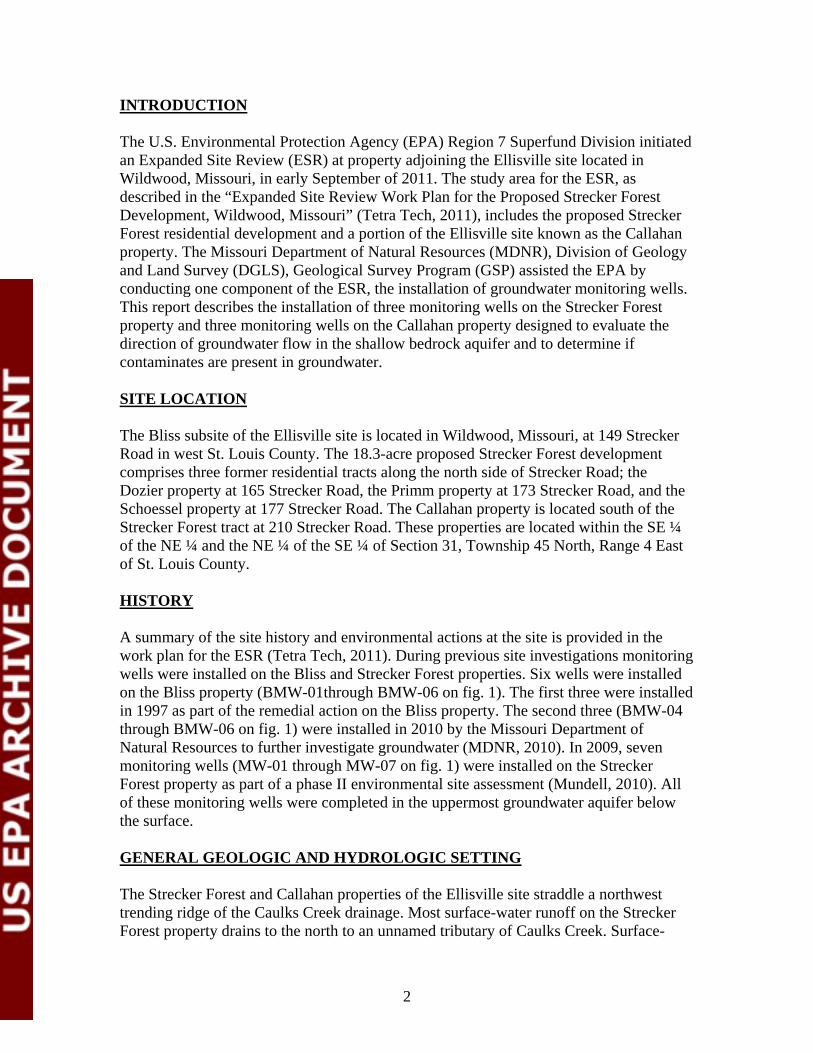
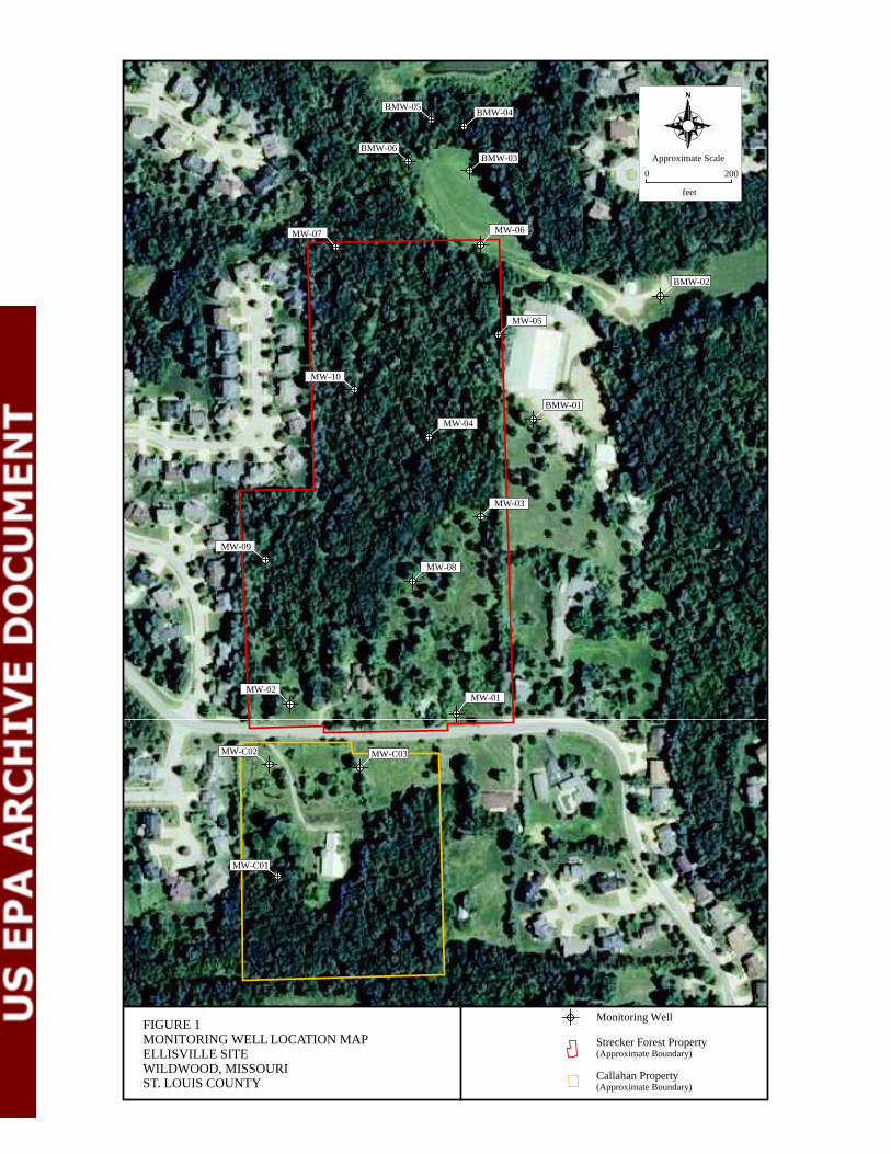
A summary of the site history and environmental actions at the site is provided in the work plan for the ESR (Tetra Tech, 2011). During previous site investigations monitoring wells were installed on the Bliss and Strecker Forest properties. Six wells were installed on the Bliss property (BMW-01through BMW-06 on fig. 1). The first three were installed in 1997 as part of the remedial action on the Bliss property. The second three (BMW-04 through BMW-06 on fig. 1) were installed in 2010 by the Missouri Department of Natural Resources to further investigate groundwater (MDNR, 2010). In 2009, seven monitoring wells (MW-01 through MW-07 on fig. 1) were installed on the Strecker Forest property as part of a phase II environmental site assessment (Mundell, 2010). All of these monitoring wells were completed in the uppermost groundwater aquifer below the surface.
GENERAL GEOLOGIC AND HYDROLOGIC SETTING
The Strecker Forest and Callahan properties of the Ellisville site straddle a northwest trending ridge of the Caulks Creek drainage. Most surface-water runoff on the Strecker Forest property drains to the north to an unnamed tributary of Caulks Creek. Surface
2

water runoff on the Callahan property drains generally south to another unnamed tributary of Caulks Creek. Caulks Creek flows north about 5 ½ miles to the Missouri River valley. Water tracing conducted by MDNR has shown that Caulks Creek and its tributaries are losing streams that recharge Lewis Spring located about 2 ½ miles north of the Ellisville site (MDNR, 1993).
Surficial materials on the hill slopes and ridge tops in the area are composed of cherty, clayrich residual materials derived from the weathering of the carbonate bedrock. The valley floors of Caulks Creek and the Bliss property are filled with silty clay surface soils over chert gravel alluvial materials. The bedrock in the area is the Mississippianage BurlingtonKeokuk Limestone formation, a gray, cherty limestone that typically displays an irregular weathered surface with cutters and pinnacles. Shallow karst development is
also typical of this bedrock formation. These surficial materials and bedrock are generally characterized as having moderate to high permeability.
WELL INSTALLATION
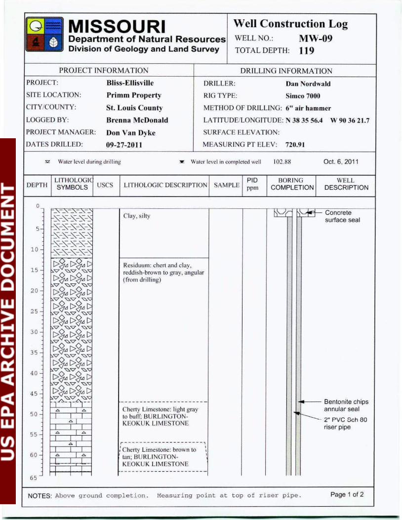
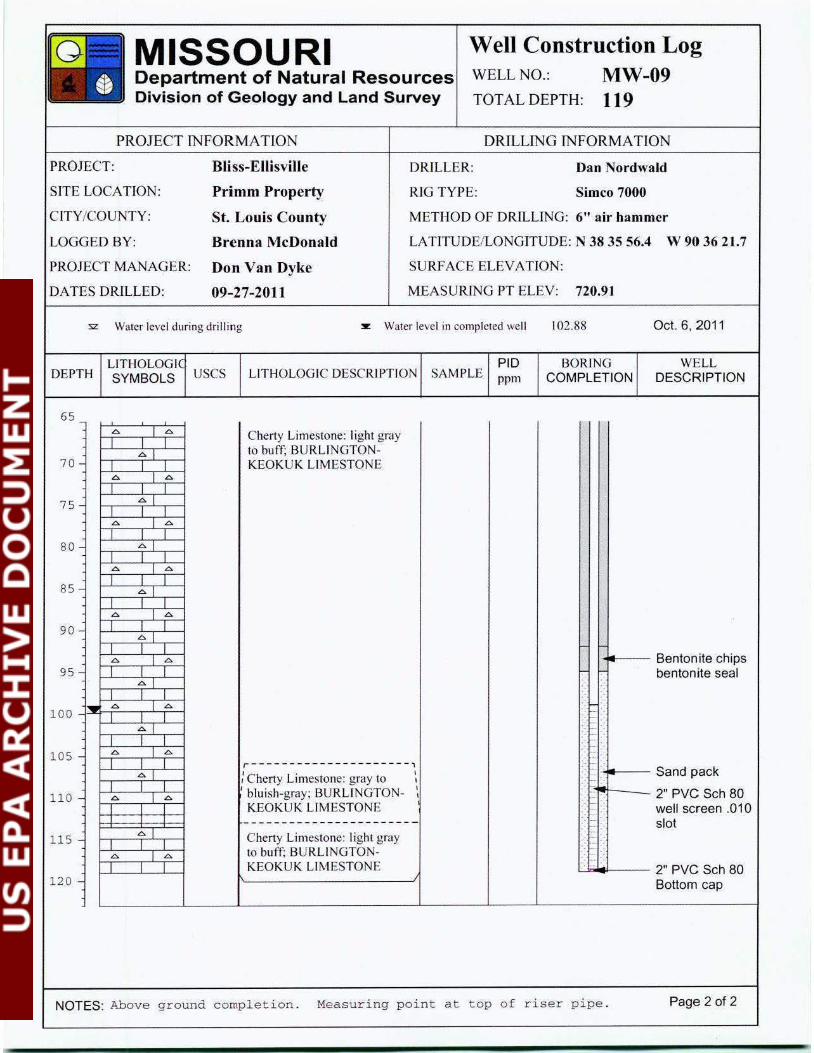
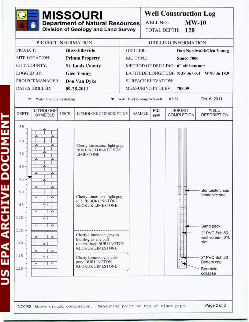
Three monitoring wells (MW8, 9, and 10) were installed on the Strecker Forest property and three (MWC01, C02 and C03) on the Callahan property by the GSP in September and October of 2011 (fig. 1). All six were drilled into bedrock and constructed to sample the uppermost groundwater aquifer, similar to the construction of existing monitoring wells. The wells were drilled with downthehole air hammer methods. The wells were drilled and constructed in accordance with the Missouri Well Construction Rules by GSP staff holding monitoringwell installer permits. All well construction materials used were purchased new and handled in a manner to keep them free of surface contaminants.
Drilling equipment was initially mobilized to the site on September 19, 2011 and drilling was initiated the next day. Drilling of the six wells was completed by October 4 with surface completions installed the following two days. The total depths of the wells
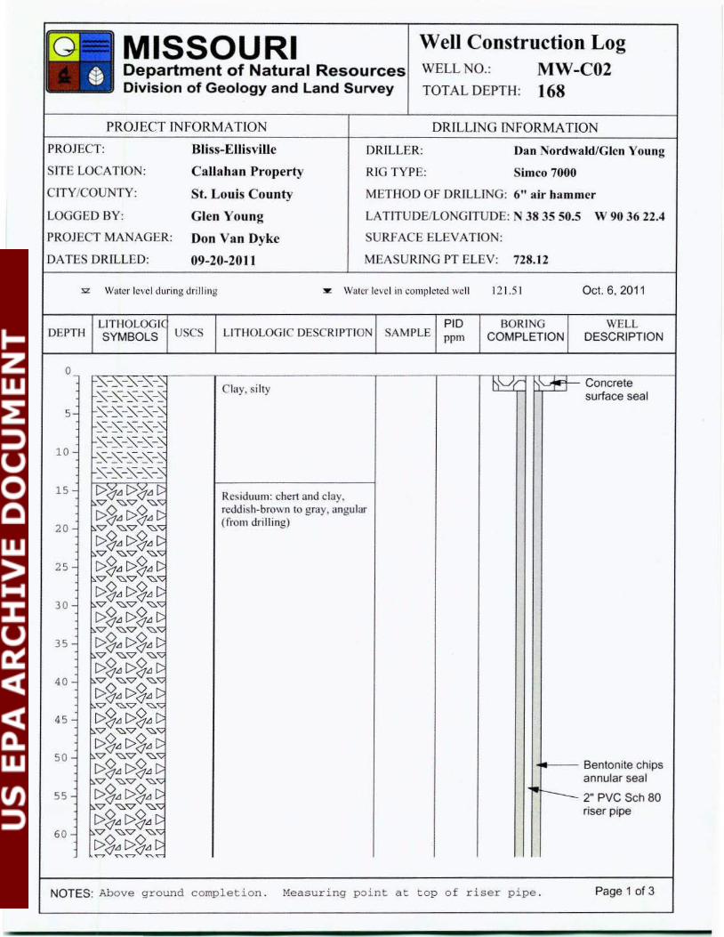
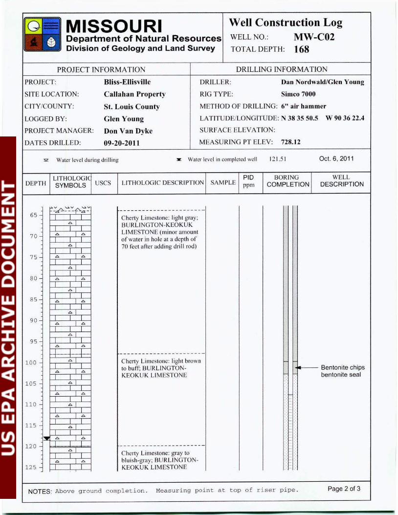
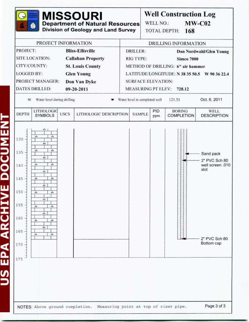
ranged from 98 to 168 feet, however, only MWC02, the first well drilled, was advanced deeper than 121 feet due to difficulty recognizing the uppermost point of saturation in that well. Groundwater recharges into MWC02 more slowly than the other wells. Due to the initial uncertainty of the water level within the well, the well is constructed with a greater length of screen and sand pack than the other wells.
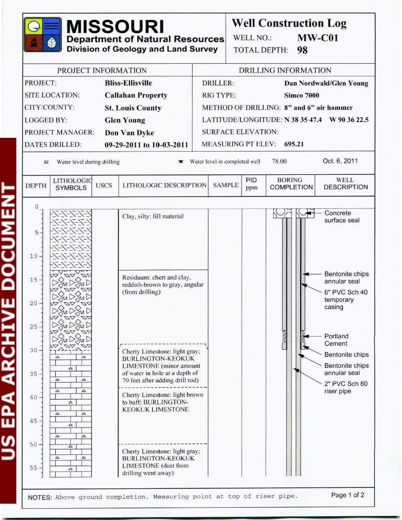
During the drilling and installation of well MWC01, positioned at the base of 1983drum excavation area, organic vapors were detected in the surficial soils near the top of bedrock. Due to the concern that contaminants were present during the drilling and installation of the well, a replacement well was drilled about 15 feet southeast of the original well. During the drilling of the replacement well, additional precautions were taken to isolate the surface soils by installing a temporary surface casing to the top of bedrock. Following the construction of the replacement well, the original MWC01 well was plugged with bentonite grout through a tremmie pipe after removing the riser pipe. The well screen could not be recovered.
3
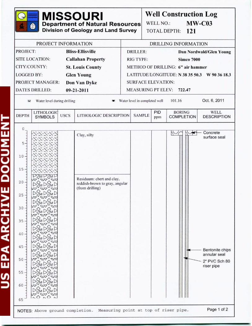
The wells were constructed with 2inch, schedule 80 PVC flushthreaded riser pipe, factory slotted (0.010 inch slots) screen and aboveground completions. A 2inch PVC well point was placed on the bottom of each well screen. The screen lengths for each well are 20 feet long, except for MWC01 which is 30 feet and MWC02 which is 60 feet. Well screens were positioned in an effort to bracket the groundwater surface within the screened interval, however, the water level in MW10 rose above the screen several feet.
Quartz sand was poured into the annular space from the surface to form a sand pack around the well screen to a depth at least 3 feet above the screen slots. Bentonite chips
were similarly emplaced from the surface to form the bentonite seal and annular seal to within a few feet of the surface. Fourinch square steel protective casings were installed at each well and set in at least 2 feet of concrete to form a surface seal. Three bolsters, set in concrete, were placed around each well, except well MW10 where only two bolsters were used since it was installed adjacent to a wooded area.
The well designations for wells installed on the Strecker Forest property (MW08, 09 and 10) were chosen to follow the numbering of the initial seven installed by Mundell. The wells installed on the Callahan property included a ‘C’ in the well number.
Measuring points on the rim of the riser pipes were also marked. Following the construction of the wells, water levels were measured in each well from the measuring point with an electronic waterlevel meter.
Following construction of the wells, the topofcasing measuringpoint elevations were surveyed using a selfleveling survey instrument and stadia rod. The measuringpoint elevations of the casing tops of existing wells installed by Mundell were used as datums
for the level survey. GSP staff developed the wells by surging and pumping them with a submersible pump and or bailer. Well construction details and location coordinates for the six wells are listed in table 1 below.
Table 1. Location coordinates and construction details for newly installed wells. MW08 MW09 MW10 MWC01 MWC02 MWC03
Latitude (dms) 38 35 55.2 38 35 56.4 38 36 00.4 38 35 47.4 38 35 50.5 38 35 50.3 Longitude (dms) 90 36 17.2 90 36 21.7 90 36 18.9 90 36 22.5 90 36 22.4 90 36 18.3 Borehole diameter (inches)
6.25 6.25 6.25 6.25 6.25 6.25
Total depth (ft) 112 119 120 98 168 121
Screen length (ft) 20.0 20.0 20.0 30.0 60.0 20.0
Measuring point elevation (ft msl)
713.71 720.91 705.09 695.21 728.12 722.47
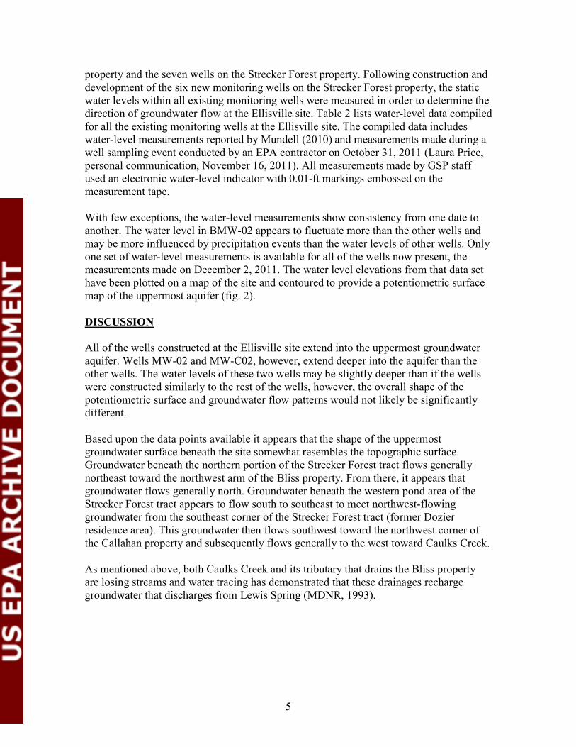
Construction diagrams for the wells are attached to this report. Also attached are copies of daily field notes recorded during the project.
WATER LEVEL MEASUREMENT
In May of 2011the Geological Survey Program began measuring water levels monthly in monitoring wells at the Ellisville site, including the six existing wells on the Bliss
4
property and the seven wells on the Strecker Forest property. Following construction and development of the six new monitoring wells on the Strecker Forest property, the static water levels within all existing monitoring wells were measured in order to determine the direction of groundwater flow at the Ellisville site. Table 2 lists waterlevel data compiled for all the existing monitoring wells at the Ellisville site. The compiled data includes
waterlevel measurements reported by Mundell (2010) and measurements made during a well sampling event conducted by an EPA contractor on October 31, 2011 (Laura Price, personal communication, November 16, 2011). All measurements made by GSP staff used an electronic waterlevel indicator with 0.01ft markings embossed on the measurement tape.
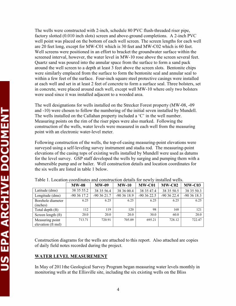
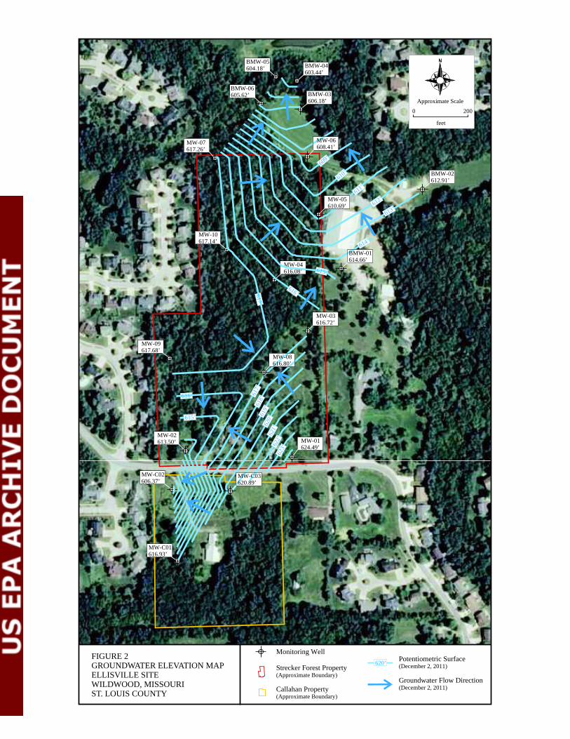
With few exceptions, the waterlevel measurements show consistency from one date to another. The water level in BMW02 appears to fluctuate more than the other wells and may be more influenced by precipitation events than the water levels of other wells. Only one set of waterlevel measurements is available for all of the wells now present, the measurements made on December 2, 2011. The water level elevations from that data set have been plotted on a map of the site and contoured to provide a potentiometric surface map of the uppermost aquifer (fig. 2).
DISCUSSION
All of the wells constructed at the Ellisville site extend into the uppermost groundwater aquifer. Wells MW02 and MWC02, however, extend deeper into the aquifer than the other wells. The water levels of these two wells may be slightly deeper than if the wells
were constructed similarly to the rest of the wells, however, the overall shape of the potentiometric surface and groundwater flow patterns would not likely be significantly different.
Based upon the data points available it appears that the shape of the uppermost groundwater surface beneath the site somewhat resembles the topographic surface. Groundwater beneath the northern portion of the Strecker Forest tract flows generally northeast toward the northwest arm of the Bliss property. From there, it appears that groundwater flows generally north. Groundwater beneath the western pond area of the Strecker Forest tract appears to flow south to southeast to meet northwestflowing groundwater from the southeast corner of the Strecker Forest tract (former Dozier residence area). This groundwater then flows southwest toward the northwest corner of the Callahan property and subsequently flows generally to the west toward Caulks Creek.
As mentioned above, both Caulks Creek and its tributary that drains the Bliss property are losing streams and water tracing has demonstrated that these drainages recharge groundwater that discharges from Lewis Spring (MDNR, 1993).
5
REFERENCES
Missouri Department of Natural Resources (MDNR). 1993. Report of Water Trace, EllisvilleBliss Water Trace, St. Louis County, Missouri. Unpublished report of investigation. March 16, 1993.
Missouri Department of Natural Resources (MDNR). 2010. Monitoring Well Installation Report, BlissEllisville Site, Shallow Groundwater Investigation, St. Louis County. MDNR Division of Geology and Land Survey unpublished report. April 2010.
Mundell & Associates, Inc. (Mundell). 2010. Phase II Environmental Site Assessment Report, Proposed Strecker Forest Development Site, 165, 173 and 177 Strecker Road,
Wildwood, Missouri 63011. MUNDELL Project No. M08044. March 3, 2010.
Tetra Tech EM Inc. (Tetra Tech). 2011. Expanded Site Review Work Plan for the Proposed Strecker Forest Development, Wildwood, Missouri. Superfund Technical Assessment and Response Team (START) Contract No. EPS70601, Task Order 0230, prepared for U.S. Environmental Protection Agency, Region 7. July 1, 2011.
6

Table 2. Ellisville site well location and waterlevel information.
Well ID Latitude Longitude Latitude Longitude Installation Total Ground TOC 11/16/2009 5/4/2011
DMS DMS DDEG DDEG Date Depth (FT) Elevation Elevation SWL1 ELEV SWL ELEV BMW01 38 35 59.465 90 36 12.687 38.599851 90.603524 9/10/1997 52 651.63 35.83 615.80 BMW02 38 36 2.666 90 36 8.135 38.600741 90.60226 9/10/1997 50.3 649.93 33.80 616.13 BMW03 38 36 6.199 90 36 14.654 38.601722 90.604071 9/10/1997 54 638.15 30.48 607.67 BMW04 38 36 7.410 90 36 14.738 38.602058 90.604094 1/14/2010 65.2 637.75 642.41 35.94 606.47 BMW05 38 36 7.537 90 36 15.859 38.602094 90.604405 1/13/2010 54.4 632.45 637.21 32.66 604.55 BMW06 38 36 6.385 90 36 16.673 38.601774 90.604631 1/12/2010 62 630.53 635.15 29.37 605.78 MW01 38 35 51.582 90 36 15.480 38.597662 90.6043 10/28/2009 122 722.07 724.87 96.95 625.12 100.24 624.63 MW02 38 35 51.903 90 36 21.184 38.597751 90.605885 10/22/2009 151 724.26 727.02 110.20 614.06 113.36 613.66 MW03 38 35 56.827 90 36 14.509 38.599119 90.60403 11/3/2009 116 708.72 711.63 91.24 617.48 94.03 617.60 MW04 38 35 59.071 90 36 16.240 38.599742 90.604511 11/5/2009 73 662.53 665.48 46.78 615.75 48.78 616.70 MW05 38 36 1.701 90 36 13.742 38.600473 90.603817 11/5/2009 62 647.60 650.34 38.99 608.61 39.22 611.12 MW06 38 36 4.178 90 36 14.274 38.601161 90.603965 10/20/2009 47 637.51 640.14 28.64 608.87 31.65 608.49 MW07 38 36 4.175 90 36 19.213 38.60116 90.605337 11/6/2009 102 701.39 704.06 82.07 619.32 84.80 619.26 MW08 38 35 55.2 90 36 17.2 38.59866 90.60478 9/26/2011 112 713.71 MW09 38 35 56.4 90 36 21.7 38.599 90.60602 9/27/2011 119 720.91 MW10 38 36 00.4 90 36 18.9 38.60011 90.60525 9/28/2011 120 705.09 MWC01 38 35 47.4 90 36 22.5 38.5965 90.60625 10/3/2011 98 695.21 MWC02 38 35 50.5 90 36 22.4 38.597361 90.60622 9/20/2011 168 728.12 MWC03 38 35 50.3 90 36 18.3 38.597305 90.605084 9/21/2011 121 722.47
Notes: 1. Water levels from Mundell (2010); reported as measured from ground surface on logs. 2. Topofcasing elevations for BMW wells based on the original three Bliss wells.
7

Table 2 (cont.). Ellisville site well location and waterlevel information.
Well ID 6/3/2011 7/6/2011 8/3/2011 9/2/2011 10/6/2011 10/31/2011 12/2/2011
SWL ELEV SWL ELEV SWL ELEV SWL ELEV SWL ELEV SWL ELEV SWL ELEV BMW01 36.10 615.53 36.17 615.46 36.50 615.13 36.84 614.79 36.97 614.66 BMW02 36.55 613.38 33.99 615.94 36.88 613.05 37.05 612.88 37.02 612.91 BMW03 30.70 607.45 31.05 607.10 31.25 606.90 31.58 606.57 31.97 606.18 BMW04 36.22 606.19 36.39 606.02 36.63 605.78 36.90 605.51 38.97 603.44 BMW05 32.71 604.50 32.74 604.47 32.90 604.31 33.03 604.18 33.03 604.18 BMW06 29.54 605.61 29.49 605.66 29.65 605.50 29.70 605.45 29.53 605.62 MW01 99.78 625.09 99.65 625.22 99.37 625.50 99.70 625.17 99.96 624.91 100.38 624.49 MW02 113.23 613.79 113.17 613.85 113.10 613.92 113.15 613.87 113.17 613.85 113.52 613.50 MW03 93.90 617.73 94.04 617.59 94.11 617.52 94.41 617.22 94.67 616.96 94.91 616.72 MW04 49.05 616.43 49.04 616.44 49.15 616.33 49.10 616.38 49.16 616.32 49.40 616.08 MW05 39.31 611.03 39.40 610.94 39.56 610.78 39.56 610.78 39.66 610.68 39.65 610.69 MW06 31.65 608.49 31.65 608.49 31.65 608.49 31.65 608.49 31.69 608.45 31.73 608.41 MW07 85.01 619.05 85.20 618.86 85.42 618.64 86.35 617.71 86.65 617.41 86.80 617.26 MW08 96.49 617.22 96.61 617.1 96.91 616.80 MW09 102.88 618.03 102.92 617.99 103.23 617.68 MW10 87.53 617.56 87.63 617.46 87.95 617.14 MWC01 78.00 617.21 78.12 617.09 78.28 616.93 MWC02 121.51 606.61 124.23 603.89 121.75 606.37 MWC03 101.16 621.31 101.19 621.28 101.58 620.89
8
MW-08
MW-04
MW-05
MW-06MW-07
BMW-01
BMW-02
BMW-03
BMW-04 BMW-05
BMW-06
MW-C02
MW-C01
MW-C03
MW-01
MW-10
MW-09
MW-03
MW-02
2000
Approximate Scale
feet
FIGURE 1 MONITORING WELL LOCATION MAP ELLISVILLE SITE WILDWOOD, MISSOURI ST. LOUIS COUNTY
Monitoring Well
Strecker Forest Property (Approximate Boundary)
Callahan Property (Approximate Boundary)
MW-04 616.08’
MW-07 617.26’
BMW-02 612.91’
BMW-03 606.18’
BMW-04 603.44’
BMW-05 604.18’
BMW-06 605.62’
MW-C02 606.37’
MW-C01 616.93’
MW-01 624.49’
MW-10 617.14’
MW-09 617.68’
MW-03 616.72’
MW-02 613.50’
2000
Approximate Scale
feet
FIGURE 2 GROUNDWATER ELEVATION MAP ELLISVILLE SITE WILDWOOD, MISSOURI ST. LOUIS COUNTY
Monitoring Well
Strecker Forest Property (Approximate Boundary)
Callahan Property (Approximate Boundary)
MW-08 616.80’
MW-05 610.69’
609’
610’
611’
612’
613’
614’
BMW-01 614.66’
615’
616’617’
616’
615’
617’
61
8’
619’
620’
621’
622’
62
3’
MW-06 608.41’
MW-C03 620.89’
Potentiometric Surface (December 2, 2011)
Groundwater Flow Direction (December 2, 2011)
620’
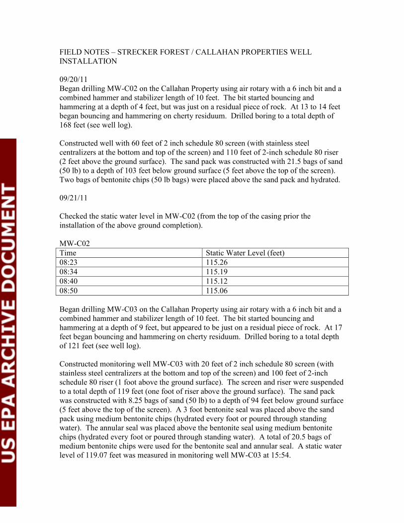
FIELD NOTES – STRECKER FOREST / CALLAHAN PROPERTIES WELL INSTALLATION
09/20/11 Began drilling MWC02 on the Callahan Property using air rotary with a 6 inch bit and a combined hammer and stabilizer length of 10 feet. The bit started bouncing and hammering at a depth of 4 feet, but was just on a residual piece of rock. At 13 to 14 feet began bouncing and hammering on cherty residuum. Drilled boring to a total depth of 168 feet (see well log).
Constructed well with 60 feet of 2 inch schedule 80 screen (with stainless steel centralizers at the bottom and top of the screen) and 110 feet of 2inch schedule 80 riser (2 feet above the ground surface). The sand pack was constructed with 21.5 bags of sand (50 lb) to a depth of 103 feet below ground surface (5 feet above the top of the screen).
Two bags of bentonite chips (50 lb bags) were placed above the sand pack and hydrated.
09/21/11
Checked the static water level in MWC02 (from the top of the casing prior the installation of the above ground completion).
MWC02 Time Static Water Level (feet) 08:23 115.26 08:34 115.19 08:40 115.12 08:50 115.06
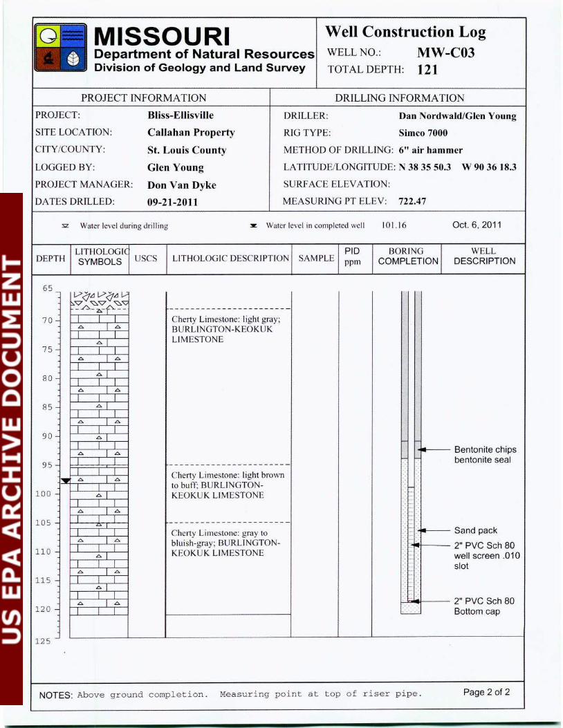
Began drilling MWC03 on the Callahan Property using air rotary with a 6 inch bit and a combined hammer and stabilizer length of 10 feet. The bit started bouncing and hammering at a depth of 9 feet, but appeared to be just on a residual piece of rock. At 17 feet began bouncing and hammering on cherty residuum. Drilled boring to a total depth of 121 feet (see well log).
Constructed monitoring well MWC03 with 20 feet of 2 inch schedule 80 screen (with stainless steel centralizers at the bottom and top of the screen) and 100 feet of 2inch schedule 80 riser (1 foot above the ground surface). The screen and riser were suspended to a total depth of 119 feet (one foot of riser above the ground surface). The sand pack was constructed with 8.25 bags of sand (50 lb) to a depth of 94 feet below ground surface (5 feet above the top of the screen). A 3 foot bentonite seal was placed above the sand pack using medium bentonite chips (hydrated every foot or poured through standing water). The annular seal was placed above the bentonite seal using medium bentonite chips (hydrated every foot or poured through standing water). A total of 20.5 bags of medium bentonite chips were used for the bentonite seal and annular seal. A static water level of 119.07 feet was measured in monitoring well MWC03 at 15:54.
09/22/11
A static water level of 107.00 feet was measured in monitoring well MWC03 at 07:42.
Returned top monitoring well MWC02 and emplaced the annular seal using medium bentonite chips (hydrated every foot or poured through standing water). A total of 21.5 bags of medium bentonite chips (50 lb bags) were used for the bentonite seal and annular seal.
Began drilling MWC01 on the Callahan Property using air rotary with a 6 inch bit and a combined hammer and stabilizer length of 10 feet. The bit started bouncing and hammering at a depth of 12 feet and a strong toluene type odor was present. Had a hard time keeping hammer operating so added water at residuum/bedrock interface to clean out the hole after cleaning the hammer out. Had to add a little water to hole at a depth of 50 to 70 feet to keep the dust down. Drilled boring to a total depth of 100 feet. There were a few gallons of water that blew out of the hole after waiting about 20 minutes.
Constructed well with 20 feet of 2 inch schedule 80 screen (with stainless steel centralizers at the bottom and top of the screen) and 80 feet of 2inch schedule 80 riser (2 foot above the ground surface). The screen and riser were suspended to a total depth of 98 feet (two foot of riser above the ground surface). The sand pack was constructed with 8 bags of sand (50 lb bags) to a depth of 73 feet below ground surface (5 feet above the top of the screen). A 3 foot bentonite seal was placed above the sand pack using medium bentonite chips (hydrated every foot or poured through standing water). The annular seal was placed above the bentonite seal using medium bentonite chips (hydrated every foot or poured through standing water). A total of 16 bags of medium bentonite chips were used for the bentonite seal and annular seal. A static water level of 73.85 feet was
measured in monitoring well MWC01 at 18:23. There was still an odor to the well at this time.
09/26/11
Brenna McDonald onsite to log wells.
Began drilling MW08 on the Primm Property using air rotary with a 6 inch bit and a combined hammer and stabilizer length of 10 feet. Drilled boring to a total depth of 112 feet (see well log).
Constructed monitoring well MW08 with 20 feet of 2 inch schedule 80 screen (with stainless steel centralizers at the bottom and top of the screen) and 100 feet of 2inch schedule 80 riser (cut off 3.5 feet above the ground surface).
The sand pack was constructed with 7 bags of sand (50 lb bags) to a depth of 85.5 feet below ground surface (6.5 feet above the top of the screen). A 3 foot bentonite seal was
placed above the sand pack using medium bentonite chips (hydrated every foot or poured through standing water). The annular seal was placed above the bentonite seal using medium bentonite chips (hydrated every foot or poured through standing water). A total of 20 bags of medium bentonite chips were used for the bentonite seal and annular seal.
09/27/11
Brenna McDonald onsite to log wells.
Began drilling MW09 on the Primm Property using air rotary with a 6 inch bit and a combined hammer and stabilizer length of 10 feet. Drilled boring to a total depth of 119 feet (see well log). Went to lunch and had water in the hole when they got back.
Constructed monitoring well MW09 with 20 feet of 2 inch schedule 80 screen (with stainless steel centralizers at the bottom and top of the screen) and 100 feet of 2inch schedule 80 riser (1 foot above the ground surface).
The sand pack was constructed with 6.5 bags of sand (50 lb bags) to a depth of 95 feet below ground surface (4 feet above the top of the screen). A 3 foot bentonite seal was
placed above the sand pack using medium bentonite chips (hydrated every foot or poured through standing water). The annular seal was placed above the bentonite seal using medium bentonite chips (hydrated every foot or poured through standing water). A total of 23.5 bags of medium bentonite chips were used for the bentonite seal and annular seal.
09/28/11
Measured static water level in monitoring well MWC01 at 77.19 feet below the top of casing (uncompleted well) at 08:03. Bailed 5 gallons of water from well with 3 foot stainless steel bailer. Remeasured static water level at 85.01 feet at 08:41 and 84.44 feet at 08:51. Put Grundfos pump in well with garden hose and tried to pump water. Pumped approximately ¼ gallon then it stopped pumping (pumped the hole dry filling the hose).
Began drilling MW10 on the Primm Property using air rotary with a 6 inch bit and a combined hammer and stabilizer length of 10 feet. The bit started bouncing and hammering at a depth of 10 feet. Bit was getting hung up on a small ledge at approximately 25 feet (having a hard time lowering tools into hole with just the winch).
Drilling dust went away at a depth of approximately 90 feet. Drilled boring to a total depth of 120 feet.
Constructed well with 20 feet of 2 inch schedule 80 screen (with stainless steel centralizers at the bottom and top of the screen) and 100 feet of 2inch schedule 80 riser.
The screen and riser went down to a total depth of 116 feet (4 feet of riser above ground)(4 feet of sluff in the hole). The sand pack was constructed with 7.5 bags of sand (50 lb bags) to a depth of 91 feet below ground surface (5 feet above the top of the screen). A 3 foot bentonite seal was placed above the sand pack using medium bentonite chips (hydrated every foot or poured through standing water). The annular seal was
placed above the bentonite seal using medium bentonite chips (hydrated every foot or poured through standing water). A total of 22.5 bags of medium bentonite chips were used for the bentonite seal and annular seal.
09/29/11
Returned to MWC01 location to drill replacement well using a temporary surface casing.
Started drilling at 12:00 using an 8 inch bit and a combined hammer and stabilizer length of 15 feet. Green soil on stabilizer at a depth of 7 to 10 feet with strong odor. It is not know just how thick the contaminated layer was since the soil was smeared on the hammer and stabilizer. Repeatedly cleaned off the hammer and stabilizer to allow for air flow. Added a few gallons of water to help clean out the hole. Put on dust deflector and added first drill stem. Started hammering at a depth of 13 feet. Turned off water valve to insure that no more water could enter the hole, but had to turn it back on due to gumming up of the hammer. Started hammering better at a depth of 23 feet. Up and down the hole to clean it out (ribs on stabilizer getting clogged up).Hammering steady at 27 feet.
Drilled to 30 feet and cleaned out the hole. Some water in hole during cleanout. At 13:35 pulled out of the hole to set the temporary casing. Added 3 bags of medium bentonite chips to the hole and hydrated (brought the hole up to 24 feet total depth).
Set 30 feet of 6 inch schedule 40 PVC in the hole (6 feet above the ground) and waited 15 minutes for the bentonite to hydrate some. Used drill rig to push the casing down 5 feet into the bentonite (1 foot above ground). Added 2.5 bags of bentonite into the annular space between boring and casing and hydrated. Pushed the casing down the remaining one foot to ground level. Switched to 6 inch hammer and stabilizer and attempted to start drilling. The hammer got stuck in the casing and blew out the seal. Pulled the casing up 4 feet and added 2 more bags of medium bentonite chips to the bottom of the hole.
Waited 15 minutes and pushed the casing down again. Waited addition 20 minutes and attempted to drill again, but the seal blew out again. Decided to install temporary casing with cement and allow to set.
09/30/11
Pulled out the temporary casing and went back down the hole with the 8 inch hammer and stabilizer to clean out the hole. Pulled back out of the hole and added ½ bag of bentonite chips and then 4 sacks of portland cement (94 lb bags) mixed with 6 gallons of water per bag. Put the 6 inch SCH 40 PVC temporary casing back down the hole at 09:30 and added 6 bags of medium chips to annular space between boring and casing (hydrated).
10/03/11
Returned to MWC01 location and measured 26 feet to the bottom of the hole inside the casing. Put 6 inch hammer and stabilizer in the hole and started drilling. Drilling dust went away at a depth of approximately 69 feet. Drilled the hole to a depth of 85 feet and waited 15 minutes and then blew about ½ gallon of water out of the hole. Decided to take the hole another 10 feet deep after comparing the total depth of the well at that time
to the water level in monitoring well MWC02 (up the hill). Drilled the hole to a total depth of 98 feet.
Constructed monitoring well with 30 feet of 2 inch schedule 80 screen (with stainless
steel centralizers at the bottom and top of the screen) and 70 feet of 2inch schedule 80 riser (2 foot above the ground surface). The sand pack was constructed with 11 bags of sand (50 lb bags) to a depth of 63 feet below ground surface (5 feet above the top of the screen). A 3 foot bentonite seal was placed above the sand pack using medium bentonite chips (hydrated every foot or poured through standing water). The annular seal was
placed above the bentonite seal using medium bentonite chips (hydrated every foot or poured through standing water) up to the bottom of the temporary casing. 6 bags of bentonite chips were used.
10/04/11
Measured static water level in the replacement monitoring well MWC01 at 92.66 feet below the top of casing (uncompleted well) at 07:45 and slowly risinig.
Pulled the temporary 6 inch PVC casing and added 6 more bags of medium bentonite chips (hydrated every foot or poured through standing water). A total of 18 bags of medium bentonite chips (including the 6 bags that were used in the annular space between the boring and temporary casing) were used for the bentonite seal and annular seal.
Finished the surface completions on monitoring wells MWC01 (except for bolsters),
MWC02, MWC03 and MW08.
10/05/11
Attempted to pull the 2” screen and riser from the original MWC01, but the riser broke off at the top joint (10 feet). Went to rolla to get extractor tool, tremmie pipe and powdered bentonite.
Returned to site and pulled a total of 80 feet of 2 inch riser from the original MWC01.
The screen broke off and would not pull due to the centralizers.
Put 1 inch PVC tremmie pipe down the hole to a depth of 70 feet (top of sand pack at 73 feet). Mixed 1 sack of bentonite powder with 25 gallons of water and pressure grouted the remaining hole with a Moyno pump.
10/06/11
Finished surface completions for MW09 and MW10.

Surveyed the top of casing of new wells to the top of casing of the nearest existing well and surveyed the 4 metal posts in the former pond area.
Station Rod Location Rod Reading (feet)
Elevation
1 Primm TOC MW02 4.22 *727.02 1 Callahan TOC MWC02 (GSP) 3.12 728.12
2 Primm TOC MW02 0.92 *727.02 2 Callahan TOC MWC03 (GSP) 5.47 722.47
3 Callahan TOC MWC02 (GSP) 1.58 728.12 3 Leg 1 17.79 711.91 4 Leg 1 0.89 711.91 4 Callahan TOC MWC01 (GSP) 17.59 695.21
5 Top of Stake 1 7.26 714.78 5 Top of Stake 2 6.70 715.34 5 Top of Stake 3 6.37 715.67 5 Top of Stake 4 6.37 715.67 5 Primm TOC MW09 (GSP) 1.13 720.91 5 Leg 1 0.25 721.79 6 Leg 1 5.76 721.79 6 Primm TOC MW02 0.53 *727.02
7 Primm TOC MW10 (GSP) 9.28 705.09 7 Leg 1 13.58 700.79 8 Leg 1 6.54 700.79 8 Primm TOC MW07 3.27 *704.06
9 Primm TOC MW03 8.29 *711.63 9 Primm TOC MW08 (GSP) 6.21 713.71
*Previously reported top of casing elevation
Measured static water levels in new wells prior to attempting to develop the wells
Location TOC elevation SWL GW Elevation Time Callahan MWC01 695.21 78.00 617.21 14:17 Callahan MWC02 728.12 121.51 606.61 09:48 Callahan MWC03 722.47 101.16 621.31 13:52 Primm MW08 713.71 96.49 617.22 14:26 Primm MW09 720.91 102.88 618.03 14:33 Primm MW10 705.09 87.53 617.56 11:41

Surged MWC02 with a 3 foot stainless steel bailer and bailed 12 gallons of water from it. Tried to surge MWC03 but the 3 foot bailer became lodged in the bottom of the hole (fines in the well locked it up).
10/12/11
Arrived at Ellisville site 13:20 to develop monitoring wells. Monitoring well MWC02. Measured static water level at 124.19 feet below the top of casing at 13:30. Started pumping with Grundfos and ½ inch poly tubing. The pump controller shut off (over amps) several times. Pumped 5 gallons of water from the well by 15:22. Pumped another 5 gallons by 16:17 and another 2 gallons by 16:40. Measured the static water level at 141.72 feet below the top of the casing at 16:54 and 141.71 feet at 17:02.
Began bailing and bailed 5 gallons of water from the well by 09:43 and another 3 gallons
of water by 09:55 Stopped bailing since lower bailer was only about ¼ full. Re
measured static water level at 109.76 feet below the top of casing at 09:58.
Moved to monitoring well MWC03. Measured static water level at 100.67 feet below the top of casing at 17:09 and 112.80 feet from the top of casing down to the top of the stuck bailer.
10/13/11
Moved to monitoring well MWC02. Measured static water level at 138.41 feet below the top of casing at 07:32.
Moved to monitoring well MW08. Measured static water level at 96.12 feet below the top of casing at 07:46. Started pumping with Grundfos and ½ inch poly tubing at 08:00.
Pumped 5 gallons of water from the well by 08:10. Pumped another 2 gallons by 08:12 and then ran out of water. Measured the static water level at 105.41 feet below the top of the casing at 08:37.
Moved to monitoring well MW10. Measured static water level at 87.08 feet below the top of casing at 09:10. Started pumping with Grundfos and ½ inch poly tubing at 09:18.
Pumped 5 gallons of water from the well by 09:26. Pumped another 5 gallons by 09:34,
another 5 gallons by 09:44 and another 2 gallons by 09:50 and then ran out of water.
Measured the static water level at 112.00 feet below the top of the casing.
Moved to monitoring well MW09. Measured static water level at 102.40 feet below the top of casing. Started pumping with Grundfos and ½ inch poly tubing. Pumped a total of 10 gallons of water from the well then ran out of water. Measured the static water level at 115.45 feet below the top of the casing at 11:09 (after pumping).
Moved to monitoring well MWC03. Measured static water level at 96.97 feet below the top of casing at 11:33. Dropped slug down the hole and surged up and down on a string.
This loosened the stuck bailer for a moment (it went up and down a couple of feet), but then it locked up again. The slug started getting hung up on the bailer string, so was
afraid to try again. Measured 113.5 feet to the top of the bailer from the top of casing.
Moved to monitoring well MWC01. Measured static water level at 77.90 feet below the top of casing at 12:05. Started pumping with Grundfos and ½ inch poly tubing at 12:14.
Pumped 5 gallons of water from the well by 12:24. Pumped another 5 gallons by 12:35 and then ran out of water. Measured the static water level at 93.51 feet below the top of the casing at 12:39.
Moved to monitoring well MWC02. Measured static water level at 137.22 feet below the top of casing at 13:05.
Moved to monitoring well MW08. Measured static water level at 97.38 feet below the top of casing at 13:12. Started pumping with Grundfos and ½ inch poly tubing at 13:45.
Pumped 5 gallons of water from the well by 13:56. Pumped another ¼ gallon and then ran out of water. Measured the static water level at 104.65 feet below the top of the casing at 14:03.
Moved to monitoring well MW10. Measured static water level at 87.18 feet below the top of casing at 14:19. Started pumping with Grundfos and ½ inch poly tubing at 14:37.
Pumped 5 gallons of water from the well by 14:55. Pumped another 5 gallons by 15:16 and then another 5 gallons by 15:58. Measured the static water level at 103.15 feet below the top of the casing at 16:02.
Measured static water levels in wells
MW09, static water level 103.09 feet at 16:29 MW08, static water level 98.92 feet at 16:36 MWC01, static water level 88.37 feet at 16:42 MWC02, static water level 136.5 feet at 16:46
10/17/11
Arrived at Ellisville site 11:45
Got water from the Callahan residence (about 50 gallons) for cleaning purposes.
Monitoring well MWC03 (3 foot stainless steel bailer stuck in the well). Measured the static water level at 101.08 feet below the top of casing. Measured 113 feet to the top of bailer from the top of casing. Put 110 feet of 1 inch tremmie pipe down the hole and pumped approximately 5 gallons of water to dislodge the bailer. The bailer wouldn’t come free. Added another 10 feet of tremmie pipe and set it on top of the bailer and the bailer went down with little resistance (just the weight if the tremmie pipe). Applied
pressure to the bailer string slowly by winding it around a brush handle. The string stretched until it broke, but the bailer didn’t move (recovered 68 feet of string). Measured 119.25 feet to top of bailer from the top of casing. Began developing well. Started pumping with the Grundfos with ½ inch poly tubing at 13:50. The pump controller kept shutting off (over amps), but pumped 5 gallons of water out of the well by 14:14 and another 5 gallons by 14:46.
Moved to monitoring well MWC02. Measured the static water level at 126.21 feet below the top of casing at 15:12. Started pumping with Grundfos and ½ inch poly tubing at 16:10. The pump controller kept shutting off (over amps), so gave up on using Grundfos. Began using 2 disposable bailers (intrain on the same line) and bailed 5 gallons of water from the well by 16:48. Bailed another 5 gallon by 17:10, another 5 gallons by 17:30, another 5 gallons by 17:44 and another 3.5 gallons by 17:54. Measured the static water level at 165.80 feet below the top of the casing at 17:56.
10/18/11
Returned to monitoring well MWC02. Measured static water level at 161.00 feet below the top of casing at 07:53. Bailed 4 gallons of water from well by 08:11. Remeasured static water level at 167.81 feet at 08:14
Moved to monitoring well MWC03. Measured static water level at 101.43 feet below the top of casing at 08:47. Began bailing and bailed 5 gallons of water from the well by 09:02 and another 3 gallons of water by 09:13. Stopped bailing since lower bailer was
only about ¼ full. Remeasured static water level at 115.79 feet below the top of casing at 09:16.
Moved to monitoring well MW08. Measured static water level at 96.43 feet below the top of casing at 09:27. Began bailing and bailed 5 gallons of water from the well by 09:43 and another 3 gallons of water by 09:55 Stopped bailing since lower bailer was
only about ¼ full. Remeasured static water level at 109.76 feet below the top of casing at 09:58.
Moved to monitoring well MW09. Measured static water level at 102.71 feet below the top of casing at 10:09. Began bailing and bailed 5 gallons of water from the well by 10:25, another 5 gallons of water by 10:42 and another gallon of water by 10:47 Stopped bailing since lower bailer was only about ½ full.
Moved to monitoring well MW10. Measured static water level at 87.37 feet below the top of casing at 11:02. Began bailing and bailed 5 gallons of water from the well by 11:17, another 5 gallons of water by 11:31, another 5 gallons of water by 11:51 and another 5 gallons of water by 12:11. Stopped bailing.
Moved to monitoring well MWC01. Measured static water level at 77.97 feet below the top of casing at 12:58. Began bailing and bailed 5 gallons of water from the well by
13:12, another 5 gallons of water by 13:23 and another 4 gallons of water by 13:35. Re
measured static water level at 98.97 feet below the top of casing at 13:37.
Moved to monitoring well MWC02. Measured static water level at 166.08 feet below the top of casing at 13:51. Began bailing and bailed 2 gallons of water from the well by 14:05.
Moved to monitoring well MWC01. Measured static water level at 98.08 feet below the top of casing at 14:14.
Moved to monitoring well MWC03. Measured static water level at 108.85 feet below the top of casing at 14:20. Began bailing and bailed 5 gallons of water from the well by 14:43 and another gallon of water by 14:48. GPS location coordinates: N 38˚ 35’ 50.3”, W 090˚ 36’ 18.3”
Moved to monitoring well MW08. Measured static water level at 98.36 feet below the top of casing at 15:00. Began bailing and bailed 5 gallons of water from the well by 15:16. Collected GPS location data N 38˚ 35’ 55.2”, W 090˚ 36’ 17.2”
Moved to monitoring well MW09. Measured static water level at 104.86 feet below the top of casing at 15:28. Collected GPS location data N 38˚ 35’ 56.4”, W 090˚ 36’ 21.7”
Moved to monitoring well MW10. Measured static water level at 87.57 feet below the top of casing at 15:37. Began bailing and bailed 4 gallons of water from the well by 15:50. Collected GPS location data N 38˚ 36’ 00.4”, W 090˚ 36’ 18.9”
Moved to monitoring well MWC02. Collected GPS location data N 38˚ 35’ 50.5”, W 090˚ 36’ 22.4”
Moved to monitoring well MWC01. Collected GPS location data N 38˚ 35’ 47.4”, W 090˚ 36’ 22.5”

Ellisville Site – Wildwood, Missouri Addendum to Field Notes, October 6, 2011
The field notes produced by Glen Young on October 6, 2011 contained top of casing survey data for the new monitoring wells (MWC01, MWC02, MWC03, MW08, MW09 and MW10) installed at the site. The survey tied the top of casing elevations of existing wells at the site to the top of casing elevations of the new wells and to the top of four stakes in the former pond area at the site. Unfortunately, the elevation data that was utilized as the top of casing elevation for the existing wells was actually the ground elevation for those wells taken from the well boring logs. This resulted in erroneous top of casing elevations for the wells reported in the field notes.
The following table contains the revised top of casing elevations for the new monitoring wells and the top of the four stakes at the site.
Location Elevation MWC01 (Top of Casing) 695.21 MWC02 (Top of Casing) 728.12 MWC03 (Top of Casing) 722.47 MW08 (Top of Casing) 713.71 MW09 (Top of Casing) 720.91 MW10 (Top of Casing) 705.09 Stake 1 (Top of Stake) 714.78 Stake 2 (Top of Stake) 715.34 Stake 3 (Top of Stake) 715.67 Stake 4 (Top of Stake) 715.67
The following page replaces the page found in the Field Notes from October 6, 2011.

Surveyed the top of casing of new wells to the top of casing of the nearest existing well and surveyed the 4 metal posts in the former pond area.
Station Rod Location Rod Reading (feet)
Elevation
1 Primm TOC MW02 4.22 *727.02 1 Callahan TOC MW02 (GSP) 3.12 728.12
2 Primm TOC MW02 0.92 *727.02 2 Callahan TOC MW03 (GSP) 5.47 722.47
3 Callahan TOC MW02 (GSP) 1.58 728.12 3 Leg 1 17.79 711.91 4 Leg 1 0.89 711.91 4 Callahan TOC MW01 (GSP) 17.59 695.21
5 Top of Stake 1 7.26 714.78 5 Top of Stake 2 6.70 715.34 5 Top of Stake 3 6.37 715.67 5 Top of Stake 4 6.37 715.67 5 Primm TOC MW09 (GSP) 1.13 720.91 5 Leg 1 0.25 721.79 6 Leg 1 5.76 721.79 6 Primm TOC MW02 0.53 *727.02
7 Primm TOC MW10 (GSP) 9.28 705.09 7 Leg 1 13.58 700.79 8 Leg 1 6.54 700.79 8 Primm TOC MW07 3.27 *704.06
9 Primm TOC MW03 8.29 *711.63 9 Primm TOC MW08 (GSP) 6.21 713.71
*Previously reported top of casing elevation
Measured static water levels in new wells prior to attempting to develop the wells
Location TOC elevation SWL GW Elevation Time Callahan MW01 695.21 78.00 617.21 14:17 Callahan MW02 728.12 121.51 606.61 09:48 Callahan MW03 722.47 101.16 621.31 13:52 Primm MW08 713.71 96.49 617.22 14:26 Primm MW09 720.91 102.88 618.03 14:33 Primm MW10 705.09 87.53 617.56 11:41
MISSOURI Department of Natural Resources Division of Geology and Land Survey
PROJECT INFORMATION
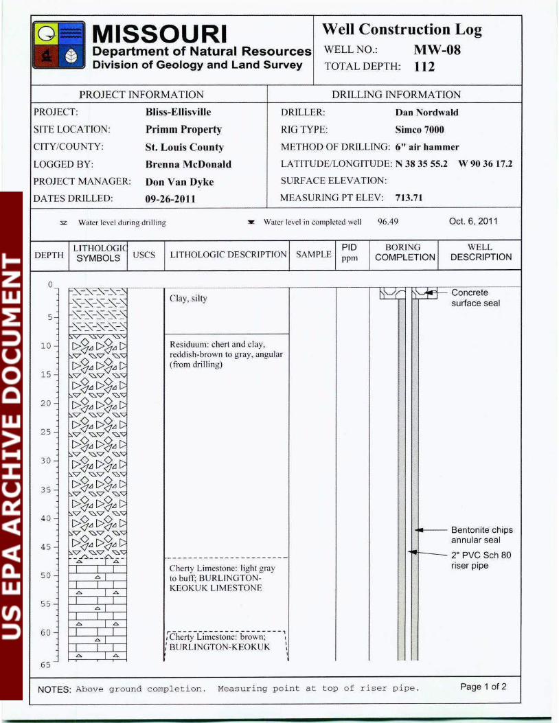
Well Construction Log WELLNO.: MW-08 TOTALDEPTH: 112
DRILLING INFORMATION
PROJECT: Bliss-E llisville
Primm Property
St. Louis County
Brenna McDonald
DRILLER: Dan Nordwald
SITE LOCATION: RTG TYPE: Simco 7000
CITY/COUNTY:
LOGGED BY:
PROJECT MANAGER: Don Van Dyke
METHOD OF DRlLLING: 6" air hammer
LATITUDE/LONGITUDE: N 38 35 55.2 W 90 3617.2
SURFACE ELEVATION:
DATES DRILLED: 09-26-2011 MEASURlNG PT ELEV: 713.71
:sz Water level during drilling ~ Water level in completed well 96.49 Oct. 6, 2011
LJTHOLOGI DEPTH SYMBOLS USCS
0
5
10
15
20
25
30
35
40
45
50
55
60
65
LITHOLOGIC DESCRIPTION SAMPLE
Clay, si lty
Residuum: chert and clay, reddish-broW11 to gTay, angular (from drilling)
Cherty Limestone: light gray to buff; BURLINGTONKEOKUK LIMESTONE
r - -----~--- ------ - - ---,i Cherty L1mestone: brown; 1
BURLINGTON-KEOKUK I
PID ppm
BORING COMPLETION
WELL DESCRIPTION
''--"'..--+-- Concrete surface seal
4-- Bentonite chips annular seal
2" PVC Sch 80 riser pipe
NOTES: Above g r ound completion . Measuring point at t op of riser pipe . Page 1 of 2

G MISSOURI Well Construction Log Department of Natural Resources WELL NO.: MW-08 Division of Geology and Land Survey TOTAL DEPTH: 112
PROJECT INFORMATION DRILLING INFORMATION
PROJECT : Bliss-Ellisville DRIL LER: Dan Nordwald
SITE LOCATION: Primm Property RIG TYPE: Simco 7000
CITY/COUNT Y: St. Louis County M ETHOD OF DRILLING: 6" air hammer
LOGGED BY: Brenna McDonald LATJTUDEILONGJTUDE: N 38 35 55.2 w 90 36 17.2
PROJECT MANAGER: Don Van Dyke URFACE ELEVATION:
DATES DRILLED: 09-26-2011 MEASURING PT ELEV: 7 13.71
:s:z Water level during drilling ~ Water level in completed well 96.49 Oct. 6. 2011
11( PID BORING WELL DEPTH SYMBOLS uses LITHOLOGJC DESCRIPTION SAMPLE ppm COMPLETION DESCRIPTION
65 I I I LIMESTONE----------------------I I I Cherty Limestone: gray to
70 ~I buff; BURLINGTONI I I
~ I~ KEOKUK LIMESTONE I I I
75 ~I
I I I ~ I ~
80 I I I ~I
I I I ~ I~ Bentonite chips
85 I I I bentonite seal ~ I
T T I
90~ I~ I I I
~ I :!I I I I . - .
95 ~ I ~ . !-I I I r------- --------------,
~I :Cherty Limestone: gray 10 I
I I I I
Sand pack bluish-gray; BURLINGTON I -100 ~ I ~ I I I KEOKUK LIMESTONE 2" PVC Sch 80 ----------------------- well screen .010
105 - ~ I ~ C'herty Limestone: light gmy; - slotI I I BURLINGTON-KEOKUK -~I
I I l LIMESTONE 110 ~ 1 ~
I I I 2" PVC Sch 80
115Bottom cap
120
125 -
NOTES: Above ground completion . Measuring point at top of riser pipe . Page 2 of 2
Well Construction Log MISSOURI WELL NO.: MW-09 Department of Natural Resources
Division of Geology and Land Survey TOTAL DEPTH: 119
sz Water level during dril ling :w: Water level in completed well 102.88 Oct. 6, 2011
PROJECT INFORMATION
PROJECT: Bliss-Ellisville
SlTE LOCATTON: Primm Property
C ITY/COUNTY: St. Louis County
LOGGED BY: Brenna McDonald
PROJECT MANAGER: Don Van Dyke
OATES DRILLED: 09-27-2011
DEPTH uses
10
15
20
25
30
35
40
45
50
55
60
65
LITHOLOGfC DESCRIPTION
Clay, silty
Residuum: chert and clay, reddish-brown to gray. angular (from drilling)
Cherty Limestone: light gray to buff; BURLINGTONKEOKUK LIMESTONE
r--- ------------------, ' C herty Limestone: brown to ~ tan; BURLINGTONKEOKUK LIMESTONE
DRILUNG fNFORMA TlON
DRILLER: Dan Nordwald
RIG TYPE: Simco 7000
METHOD OF DRILLING: 6" air hammer
LATITUDEILONGTTUDE: N 38 35 56.4 W 90 36 21.7
SURFACE ELEVATION:
MEASURfNG PT EL EV: 720.91
SAMPLE PID BOR ING WELL ppm COMPLETION DESCRIPTION
, '""'"_.....- Concrete surface seal
.,....._ _ Bentonite chips annular seal
2" PVC Sch 80 riser pipe
NOTES: Above g round completion . Measuri ng point at t op o f riser pipe . Page 1 of 2
MISSOURI Well Construction Log Department of Natural Resources WELL NO.: MW-09 Division of Geology and Land Survey TOTAL DEPTH: 119
PROJECT INFORMATION DRILLING INFORMATION
PROJECT: Bliss-Ellisville DRJLLER: Dan Nordwald
SITE LOCATION: Primm Property RIG TYPE: Simco 7000
CITY/COUNTY: St. Louis County METHOD OF DRILLING: 6" air hammer
LOGGED BY: Brenna McDonald LATTTUDEILONGJTUDE: N 38 35 56.4 w 90 36 21.7
PROJECT MANAGER: Don Van Dyke SURF ACE ELEVATION:
DATES DRILLED: 09-27-2011 MEASURING PTELEY: 720.91
sz Water level during dril ling :...: Water level in completed well 102.88 Oct. 6, 2011
LITHOLOGIC PID BORING WELL DEPTH SYMBOLS uses LITHOLOGIC DESCRIPTJON SAMPLE ppm COMPLETION DESCRIPTION
65 .0. l.o. Cherty Limestone: light gray I I I
.O.I to buff; BURLINGTON70 I I I KEOKUK LIMESTONE
.0. l .o. I I I
75 .O. I I I I .0. l .o. I I I
80 .o.j I t _l .0. 1.:>.
85 I I I
.o. l I I I .0. 1 -"""
90 I I _l .o. l
I I I .0. l .o. Bentonite chips
95 I I I bentonite seal .o.l
I I I
100 1- .0. l A . .
I I I .o.l
I I I ..
105 .0. l .o. I I I r-------- -- - --------, - .
.o. l :Cherry Limestone: gray to I
. -. Sand packI . -
I I I bluish-gray; BURLINGTON I - 2" PVC Sch 80110 .0. lA . - .
I I I KEOKUK LJMESTONE well screen .010 ------------------ ----- . - . slot
115 - .o.l Cherty Limestone: l ight gray I I I . - . .0. l A to buff: BURLINGTONI I I KEOKUK LJMESTONE 2" PVC Sch 80
120 - Bottom cap
NOTES: Above ground completion . Measuring point at top of riser pipe. Page 2 of 2

-----------------------
--- ------------------- -
Well Construction Log G MISSOURI WELL NO.: MW-10Department of Natural Resources
Division of Geology and Land Survey TOTAL DEPTH: 120
PROJECT INFORMATION DRILLING INFORMATION
PROJECT: Bliss-EI.Iisville DRILLER: Dan Nordwald/Gien Young
SITE LOCATION: Primm Property RIG TYPE: Simco 7000
CITY/COUNTY: St. Louis County METHOD OF DRILLING: 6" air hammer
LOGGED BY: Glen Young LATITUDE/LONGITUDE: N 38 36 00.4 W 90 36 18.9
PROJECT MANAGER: Don Van Dyke SURFACE ELEVATION:
DATES DRILLED: 09-28-2011 MEASURING PT ELEV: 705.09
sz Water level during drilling :!!: Water level in completed well 87.53 Oct. 6, 2011
PID BORING WELLLITHOLOGIC LITHOLOGIC DESCRfPTION SAMPLE DEPTH SYMBOLS USCS DESCRIPTIONCOMPLETIONppm
rT"""<O-..-~.,-.....-----.--;- ~-----~------ - - --- - - .-----,------,.---..D9-,---,...-,-,"T';::::.r:.J..J..:::,i c-on_d d /"' _ .....,~-= _cr_e_te--~ 1est uum: c 1ert an c ay,
reddish-brown to gray, angular (from drilling)
Cherty Limestone: light g ray; BURLINGTON-KEOKUK LIMESTONE
r---- ------------- ---- , :Cherry Limestone: brown; \
BURLINGTON-KEOKUK LIMESTONE
Cherty Limestone: light gray to buff; BURLINGTONKEOKUK LIMESTONE
surface seal
...___ Bentonite chips annular seal
~~--- 2" PVC Sch 80 riser pipe
NOTES: Above ground completion. Measuring point at top of riser pipe . Page 1 of 2
Well Construction LogG MISSOURI WELL NO.: MW-10Department of Natural Resources
Division of Geology and Land Survey TOTAL DEPTH: 120
PROJECT TNFORMATION
PROJECT: Bliss-Ellisville
SITE LOCATION: Primm Property
CITY/COUNTY: St. Louis County
LOGGED BY: Glen Young
PROJECT MANAGER: Don Van Dyke
DATES DRILLED: 09-28-201 1
DRI LUNG TNFORMATION
DRILLER: Dan Nordwald/ GJcn Young
RIG TYPE: Simco 7000
METHOD OF DRILUNG: 6" air hammer
LATITUDE/LONGITU DE: N 38 36 00.4 w 90 36 18.9
SURFACE ELEVATION:
MEASURfNG PT ELEV: 705.09
:sz Water level during drilling :!!: Water level in completed well 87.53 Oct. 6, 2011
PID BORlNG WELLLITHOLOGIC DEPTH uses LITHOLOGIC DESCRIPTION SAMPLE ppm COMPLETION DESCRIPTIONSYMBOLS
A I65
7 0
75
80
85
90
95
100
1 05
110
115
120
....
r-- -- ------------------ Cherty Limestone: light gray: BURLINGTON-KEOKUK LIMESTONE
----------------------Cherty Limestone: light gray to buff; BURLINGTONKEOKUK LIMESTONE
·- -------------- ------ - Cherty Limestone: gray to bluish-gray and buff (alternating); BURLI GTONKEOKUK LIMESTONE
1;---------- --------- , Cherty Limestone: bluish-gray: BURLlNGTON-KEOKUK LIMESTONE
I I I A fA I I I A lA I I I
A I I I I A f A I I I
A I I I I A fA I I I
A I I I I A f A I I I I I I A f A I I I
A I I I I A f A I I I
A f I I I A f A I I I I I I A fA I I I
A I I I I A f A I I I
I A lA I I I
:· ~ ·: --
-
--
. ---
/ /
, ~
Bentonite chips bentonite seal
Sand pack
2" PVC Sch 80 well screen .010 slot
2" PVC Sch 80 Bottom cap
/ ' /~ ....__ Borehole
.II.
NOTES: Above ground completion. Measu ring point at top of riser p i p e . Page 2 of 2
MISSOURI Department of Natural Resources Division of Geology and Land Survey
PROJECT lNFORMATION
Well Construction Log WELL NO.:
TOTAL DEPTH:
MW-COl 98
DRILLING rNFORMA TION
PROJECT: Bliss-Ellisville
Callahan Property
St. Louis County
Glen Young
DRILLER: Dan Nordwald/Glen Young
Simco 7000SITE LOCATION: RIG TYPE:
CITY/COUNTY: METHOD OF DRJLLJNG: 8" and 6" air hammer
LOGGED BY:
PROJECT MANAGER: Don Van Dyke
LATITUDE/LONGITUDE: N 38 35 47.4 W 90 36 22.5
SURF ACE ELEVATION:
DATES DRILLED: 09-29-2011 to 10-03-2011 MEASURING PT ELEV: 695.21
:sz Water level during drill ing ~ Water level in complcred well 78 .00 Oct. 6, 2011
LIT HOLOGIC D EPTH SYMBOLS USCS
0_ -~-~-~-~-~ ~-~-- -~
5 - ~-~-- -~ ~-~-- -~ s:-~-- -~
10 ~-~-- -~ -~-~-~-- -~
15 --:.."V'! ~"Vv ":>.'V
e>S~ e>S~ D ":>."V ~"V ~'V
20e>S~ e>S~ D
"::>."V ~"V ~'V
e>S~ e>S~ D ":>."\?: ~"V ~'V
25 e>S~ e>S~ c: p."V ~"V ~"\:;
e>S~ e>S~ c: 30 ~-;" ~~.c.,·~~
6. I L:>. I I I
L:>. l 35 I I I
6. I L:>.
I I I 6. 1 6.
4 0 - I I I .t:.l
I I I 6. IL:>.
45 I I I AI
I I I A 1 6.
50 I I I 6.
I I I 6. j L:>.
I I I55 6. 1
I I I
LITHOLOGIC DESCRIPTION SAMPLE
Clay, s ilty: fill material
Residuum: chert and clay, reddish-brown to gray, angular {from drilling)
r- -- -- ---- ------- ----- ~
C herty Limestone: light g ray; BURLINGTON-KEOKUK LIMESTONE (minor amount of water in hole at a depth of 70 feet af ter adding drill rod)
~----- ---------- - - ---- --
C herty Limestone: light brown to buff: BURLINGTONKEOKUK LIMESTONE
Cherty Limestone: light gray; BURLINGTON-KEOKUK LIMESTONE (dust from drilling went away)
PID ppm
BORING COMPLETION
WELL DESCRIPTION
-&?r ~ Concrete surface seal
1-- Bentonite chips ""'" annular seal
i ---......__ 6" PVC Sch 40 temporary casing
1~:1~- Portland Cement
I -~ -... Bentonite chips
~~ ~Bentonite chips r.-~ annular seal
I ~ 2" PVC Sch 80 riser pipe
NOTES: Above ground completion . Measuring p oint at top o f riser pipe . Page 1 of 2

-----------------------
-------- ------- --- ------
75
Well Construction Log G MISSOURI WELL NO.: MW-COl Department of Natural Resources
Division of Geology and Land Survey TOTAL DEPTH: 98
PROJECT TNFORMATLON
PROJECT: Bliss-Ellisville
SITE LOCATION: Callahan Property
C ITY /COUNTY: St. Louis County
LOGGED BY: Glen Young
PROJECT MANAGER: Don Van Dyke
DATES DRILLED: 09-29-2011 to 10-03-2011
DRILLING INFORMATION
DRILLER: Dan Nordwald/Gicn Young
RIG TYPE: Simco 7000
METHOD OF DRILLING: 8" and 6" a ir hammer
LATITUDE/LONGITUDE: N 38 35 47.4 w 90 36 22.5
SURFACE ELEVATION:
MEASURING PT ELEV: 695.21
sz Water level during drilling ~ Water level in completed well 78.00 Oct. 6, 2011
LITHOLOGIC PIO BORING WELL DEPTH uses LITHOLOGIC DESCRIPTION SAMPLESYMBOLS ppm COMPLETION DESCRIPTION
60
65
70
I.::!I!
80
85
90
95
100
·.o. l .o. I I I
.o. l I I I .0. l .o. I I I
.o.l I I I .0. l .o. I I I I I I
.o. l I I I .0. l .o. I I I
.o.l I I I .0. l .o. I I I
.o. l I I I .0. l.o. I I I
.0. l.o. I I I
.o.l I I I .0. l .o. I I I
.o. l I I I .0. l .o. I I I
Bentonite chips bentonite seal ~
Cherty L imestone: l ight b rown -to buff: BURLINGTON -
KEOK UK LIMESTONE
Sand pack
2" PVC Sch 80 well screen .010 slotCherty L imestone: gray to
bluish-gray; BURLINGTONKEOKUK LIMESTONE
. .·
. . 2" PVC Sch 80 bottom cap
NOTES: Above ground completion. Measuring point at top of riser pipe. Page 2 of 2
Well Construction LogMISSOURI WELL NO.: MW-C02 Department of Natural Resources
Division of Geology and Land Survey TOTAL DEPTH: 168
PROJECT INFORMATION DRILLING INFORMATION
PROJECT: Bliss-Ellisville DRJLLER: Dan Nordwald/Gicn Young
S1TE LOCATJON: Callahan Proper ty RIG TYPE: Simco 7000
CITY/COUNTY: St. Louis County METHOD OF DRILLING: 6" air bammer
LOGGED BY: Glen Young LATJTUDEILONGJTUDE: N 38 35 50.5 W 90 36 22.4
PROJECT MANAGER: Don Van Dyke SURFAC E ELEVATION:
DATES DRILLED: 09-20-20 II MEASURING PT ELEV: 728.12
:s:z Water level during drilling s Water level in completed well I 2 1.51 Oct. 6, 2011
PID BORING WELL DEPTH uses LITHOLOGIC DESCRIPTION SAMPLE DESCRIPTIONppm COMPLETION
0
5
10
15
20
25
30
35
40
4 5
50
55
60
Clay, s ilty
Residuum: chert and clay. reddish-brown to gray, angular (from drilling)
........-----.--- Concrete surface seal
..---- Bentonite chips annular seal
2" PVC Sch 80 riser pipe
NOTES: Above ground completion . Measuring poin t a t top of r iser p ipe . Page 1 of 3
MISSOURI Well Construction Log Department of Natural Resources WELL NO.: MW-C02 Division of Geology and Land Survey TOTAL DEPTH: 168
PROJECT IN FORMATlON DRILLING INFORMATION
PROJECT: Bliss-Ellisville DRILLER: Dan Nordwald/Cicn Young
SlTE LOCATION: CaUahan P roperty RIG TYPE: Simco 7000
CITY /COUNTY: St. Louis County METHOD OF DRILLING: 6" air hammer
LOGGED BY: Glen Young LATITUDE/LONGITUDE: N 38 35 50.5 w 90 36 22.4
PROJECT MANAGER: Don Van Dyke SURFACE ELEVATION:
DATES DRILLED: 09-20-2011 MEASURING PT ELEV: 728.12
:sz Water level during drilling ~ Water level in completed well 121.51 Oct. 6 , 2011
LITHOLOGIC PID BORfNG WELL DEPTH SYMBOLS uses LITHOLOGfC DESCRIPTION SAMPLE ppm COMPLETION DESCRIPTION
~v ~":.0-..~v '
:.p_ - ;a: ---- --- --- ---- -------65 I I T Cherty Limestone: light gray:
.c. I BURLINGTON-KEOKUKI I I
70 L>. I L>. LIMESTONE (minor amount I I I ofwater in hole at a depth of
.c. I 70 feet after adding drill rod)I I I
75 .00. l .o. I I I
.c. I I I I
80 A l A I I I
AI
85I I I A lA I I I
A I 90 I I I
A l A I I I
A I 9 5 I I I
A lA I I I -- ----- ------ --------
100 - A I Cherty L imestone: light brown I I I to buff; BURLINGTON- Bentonite chips A l A I I I KEOKUK LIMESTONE bentonite seal
105 - .c. I I I I A l A I I I
110 - A I -. -I I I -. A lA -
I I T ..
1 1 5 -. .
AI I I I - .
~ .00. JA -I I I120 - -- --------------------A I Cherty Limestone: gray to I I I . - . .00. lA bluish-gray; BURLINGTON
125 I I I KEOKUK LIMESTONE . - .
NOTES: Above ground completion . Measu ring point at top of riser pipe . Page 2 of 3
G MISSOURI Well Construction Log Department of Natural Resources WELL NO.: MW-C02 Division of Geology and Land Survey TOTAL DEPTH: 168
PROJECT INFORMATION DRILLING INFORMATION
PROJECT: Bliss-E llisville DRILLER: Dan Nordwald/Gicn Young
SITE LOCATION: Callahan Property RIG TYPE: Simco 7000
CITY/COUNTY: St. Louis County METHOD OF DRILLING: 6" air hammer
LOGGED BY: Glen Young LATITUDEILONGJTUDE: N 38 35 50.5 w 90 36 22.4
PROJECT MANAGER: Don Van Dyke SURFACE EL EVATION:
DATES DRILLED: 09-20-2011 MEASURING PT ELEV: 728.12
:sz Wuter level during drilling :!!: Water level in completed well 12 1.51 Oct. 6 , 2011
.ITHOLOGIC PID BORING WELL DEPTH SYMBOLS uses LITHOLOGIC DESCRIPTION SAMPLE ppm COMPLETION DESCRIPTION
.O. t -I I I --. - . .0. l .o. -
130 I I I --.o.l -I I I -. - .
.0. l.o. -135 I I I
. -Sand pack
.o.l -I I I
- 2" PVC Sch 80-140 .0. l .o. - well screen .01 0
I I I - slot.o. l I I I -- .
145 .0. l r>. --I I I -.o.l
I I I 150 .0. l.o. -
I I I .· ~: :.o.l I I I -
155 -.0. l r>. -I I I --.o. l -
160 I I I -L>. l r>. -I I I -.o. l -
165 - I I I L>. lr>. I I I - 2" PVC Sch 80
170 Bottom cap
175
NOTES: Above ground completion . Measuring point at top of riser pipe. Page 3 of 3
MISSOURI Department of Natural Resources Division of Geology and Land Survey
Well Construction Log WELL NO.: MW-C03
121TOTAL DEPTH:
PROJECT INFORMATlON DRILLING INFORMATION
PROJECT: Bliss-EIIisviUe DRJLLER: Dan Nordwald/Gien Young
SIT E LOCATION: Callahan Property RJG TYPE: Simco 7000
CITY/COUNTY: St. Louis County METHOD OF DRILLING: 6" air hammer
LOGGED BY: Glen Young LA TITUDEILONGITUDE: N 38 35 50.3 W 90 36 18.3
PROJECT MANAGER: Don Van Dyke SURFACE ELEVATION:
DATES DRil.LED: 09-21-2011 MEASURJNG PT ELEV: 722.47
sz Water level during drilling :w: Water level in completed well I0 I .16 Oct. 6, 2011
DEPTH LITHOLOGI SYMBOLS USCS LITHOLOGIC DESCRIPTION SAMPLE
PID ppm
BORING COMPLETION
WELL DESCRIPTION
0
5
10
15
20
25
30
35
40
45
50
55
60
65
Clay, silty
Residuum: chert and clay, reddish-brown to gray, ang ular ( from drill ing)
-.......----.-- Concrete surface seal
,....___ Bentonite chips annular seal
2" PVC Sch 80 riser pipe
NOTES: Above ground completion. Measur ing point at top of riser pipe . Page 1 of 2
MISSOURI Well Construction Log Department of Natural Resources WELL NO.: MW-C03 Division of Geology and Land Survey TOTAL DEPTH: 121
PROJECT INFORMATION DRILLING INFORMATION
PROJECT: Bliss-Ellisville DRJLLER: Dan Nordwald/Gien Young
SlTE LOCATION: Callahan Property RTG TYPE: Simco 7000
CITY/COUNTY: St. Louis County METHOD OF DRJLLING: 6" air hammer
LOGGED BY: Glen Young LATTTUDEILONGITUDE: N 38 35 50.3 w 90 36 18.3
PROJECT MANAGER: Don Van Dyke SURFACE ELEVATION:
DATES DRILLED: 09-21-2011 MEASURING PT ELEV: 722.47
:sz Water level during drilling :'!!: Water level in completed well 101.16 Oct. 6, 2011
LITHOLOGIC PID BORING WELL DEPTH SYMBOLS uses LITHOLOG[C DESCRIPTION SAMPLE ppm COMPLETION DESCRIPTION
65 L->.(1<l L->.(1.1 v ~"V: '0..~~-"-v ----------------------~- ·
70 I I I Cherty Limestone: light gray; .0. l .o. BURLINGTON-KEOKUK I I I
.o. l LIMESTONE 75 I I I
.0. l .o. I I I
8 0 .o. J I I I .0. I .o. I I I
85 .o.J I I I .0. l .o. I I I
90 .o. l I I I Bentonite chips .0. l.o.
95 I I I -------------- ----- ---- bentonite seal I I I Cherty Limestone: light brown,... A lA I I I to buff; B URLINGTON
100 - .o. l KEOKUK LIMESTONE -
I I I -. A l A -
105 - I I I ~-- - - - ------- - - --------- -. Sand pack I I I Cherty Limestone: gray to ·
A l A bluish-gray; BURLINGTON -I I I - 2" PVC Sch 80
110 - A I KEOKUK LIMESTONE well screen .010 - . I I I - . slot-A [ A
115 I I I -A I .-.
I I I 2" PVC Sch 80 A l A .. 120 - I I I .. . Bottom cap -'--
125
NOTES: Above ground complet ion. Measuring point at top of r i ser pipe . Page 2 of 2