Monitoring system in new dormitory APISSEQ, Sisimiut...
51
General rights Copyright and moral rights for the publications made accessible in the public portal are retained by the authors and/or other copyright owners and it is a condition of accessing publications that users recognise and abide by the legal requirements associated with these rights. • Users may download and print one copy of any publication from the public portal for the purpose of private study or research. • You may not further distribute the material or use it for any profit-making activity or commercial gain • You may freely distribute the URL identifying the publication in the public portal If you believe that this document breaches copyright please contact us providing details, and we will remove access to the work immediately and investigate your claim. Downloaded from orbit.dtu.dk on: Jul 04, 2018 Monitoring system in new dormitory APISSEQ, Sisimiut, Greenland. Vladyková, Petra; Kotol, Martin Publication date: 2010 Document Version Publisher's PDF, also known as Version of record Link back to DTU Orbit Citation (APA): Vladyková, P., & Kotol, M. (2010). Monitoring system in new dormitory APISSEQ, Sisimiut, Greenland. Kgs. Lyngby: DTU Byg, Danmarks Tekniske Universitet. (Report SR xx-10).
-
Upload
trinhkhanh -
Category
Documents
-
view
218 -
download
0
Transcript of Monitoring system in new dormitory APISSEQ, Sisimiut...

General rights Copyright and moral rights for the publications made accessible in the public portal are retained by the authors and/or other copyright owners and it is a condition of accessing publications that users recognise and abide by the legal requirements associated with these rights.
• Users may download and print one copy of any publication from the public portal for the purpose of private study or research. • You may not further distribute the material or use it for any profit-making activity or commercial gain • You may freely distribute the URL identifying the publication in the public portal
If you believe that this document breaches copyright please contact us providing details, and we will remove access to the work immediately and investigate your claim.
Downloaded from orbit.dtu.dk on: Jul 04, 2018
Monitoring system in new dormitory APISSEQ, Sisimiut, Greenland.
Vladyková, Petra; Kotol, Martin
Publication date:2010
Document VersionPublisher's PDF, also known as Version of record
Link back to DTU Orbit
Citation (APA):Vladyková, P., & Kotol, M. (2010). Monitoring system in new dormitory APISSEQ, Sisimiut, Greenland. Kgs.Lyngby: DTU Byg, Danmarks Tekniske Universitet. (Report SR xx-10).

TECHICAL UNIVERSITY OF DENMARK
BY
G∙D
TU
Monitoring system in new dormitory APISSEQ Sisimiut - Greenland
Report SR xx-10 BYG·DTU December 2010

ii

i
Monitoring system in new dormitory Apisseq Sisimiut - Greenland
Authors: Petra Vladykova Martin Kotol
ii
Preface
The report on “Monitoring system in new dormitory Apisseq in Sisimiut, Greenland” contains the information and data about the system that has been selected for the monitoring of Apisseq. The report begins with brief description of the dormitory and list of sensors used for monitoring the indoor climate, energy consumption and temperature and moisture inside the construction. The report presents the locations of sensors and aspects around the sensors with relevant manuals, technical description, calibration lists and list of contacts.
March 2011 Technical University of Denmark

iii
Content
1 Introduction ............................................................................................................................................... 1
1.1 Objectives .......................................................................................................................................... 1
1.2 Key-data for the dormitory ................................................................................................................ 1
2 Monitoring system for Apisseq ................................................................................................................. 4
2.1 LONBOX system .............................................................................................................................. 4
2.2 Access information ............................................................................................................................ 4
3 The summary of measuring sensors: numbering, labelling and location .................................................. 6
3.1 Space temperature and humidity sensors ........................................................................................... 6
3.2 CO2 sensors........................................................................................................................................ 7
3.3 Opening & temperature sensors ........................................................................................................ 8
3.4 Built in sensors .................................................................................................................................. 9
3.5 Energy meters .................................................................................................................................. 10
3.6 Heat exchangers ............................................................................................................................... 12
3.7 Other meters .................................................................................................................................... 14
4 Details of sensors - description and location ........................................................................................... 15
4.1 Honeywell sensors ........................................................................................................................... 15
4.2 CO2 sensors...................................................................................................................................... 18
4.3 Opening and temperature sensors .................................................................................................... 19
4.4 Build in sensors ............................................................................................................................... 20
4.5 Energy meters .................................................................................................................................. 38
4.6 Ventilation ....................................................................................................................................... 40
5 Contact list ............................................................................................................................................... 42
5.1 Monitoring system ........................................................................................................................... 42
5.2 Sensors ............................................................................................................................................. 43
5.3 Technical University of Denmark ................................................................................................... 44
5.4 Dormitory ........................................................................................................................................ 44

Page 1 of 44
1 Introduction
The new dormitory Apisseq is an energy efficient building and the monitoring system was designed to measure consumed and produced energy as well as the quality of indoor environment. The initial design goal of minimizing operating and maintenance costs will be documented by using the monitoring system.
The Technical University of Denmark (DTU) has donated DKK 500,000 for the monitoring system that would be suitable to measure all important aspects concerning energy, indoor air quality (IAQ) and built-in moisture. The Technical University of Denmark (ARTEK, BYG and Building 101) has also donated money for the project where the selection of sensors and placement was decided.
DTU is responsible only for instalment of the monitoring system, setting up of the sensors and running the monitoring system. DTU has not been involved in the design process of the dormitory or in the actual construction of the dormitory.
1.1 Objectives
The objectives of the monitoring system are as follows:
• monitoring of overall performance of the dormitory with focus on detailed key measurements • continuous and autonomic solution for data collection (accessible online) • continuous logging of:
o IAQ (temperature, relative humidity, CO2) o opening of the windows/doors and temperature close to them o total building consumption of energy (electricity, heat) o fractions of different sources to heating (district heating, solar energy) o solar production and use of hot water o situation inside the structure (temperature and moisture content)
• each sensor will have unique name and number for identification, the name consists of shortcut for type of the sensor and its particular number
• each sensor will be supplied with calibration certificate to exactly calculate the required values
1.2 Key-data for the dormitory
Inauguration of Apisseq was on 18th of August 2010 and on 20th of November 2010
1.2.1 Space solution
The building has a circular shape and a partially heated ground floor and two upper floors. Main technical room and janitor´s office are in the heated part of the ground floor and small storage compartments (one for each apartment) are in the unheated part together with smaller technical rooms with ventilation units. The 1st and 2nd floor consist of identical flats. There is a common room with a kitchen and a laundry room on the first floor (Fig. 1Error! Reference source not found. shows the floor plans). On the second floor, the common room and laundry are replaced with flats. In the centre of the building is a glazed atrium with a staircase.
Most of the flats are meant to accommodate one person. Each flat has an entrance, bathroom and living room with a kitchenette. At the gables of the building are four bigger apartments for families and handicapped.

Page 2 of 44
Fig. 1. Floor plans
The rooms are specified in Table 1.
Table 1 - Types of flats in Apisseq
Apartment Rooms Net area [m2] Single Room 16.8 Entrance 3.3 Bathroom 2.8
Total 22,9 Two room (for handicapped) Room 22.5 Bedroom 15.8 Entrance 5.8 Bathroom 6.2
Total 50,3 Three-room Room 24.0 Bedroom 1 10.6 Bedroom 2 7.7 Entrance 4.6 Bathroom 3.3 Total 50,2
Page 3 of 44
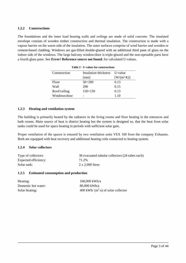
1.2.2 Constructions
The foundations and the inner load bearing walls and ceilings are made of solid concrete. The insulated envelope consists of wooden timber construction and thermal insulation. The construction is made with a vapour barrier on the warm side of the insulation. The outer surfaces comprise of wind barrier and wooden or cement-based cladding. Windows are gas-filled double-glazed with an additional third pane of glass on the indoor side of the windows. The large balcony window/door is triple-glazed and the non-openable parts have a fourth glass pane. See Error! Reference source not found. for calculated U-values.
Table 2 - U-values for constructions
Construction Insulation thickness U-value [mm] [W/(m²∙K)] Floor 50+200 0.13 Wall 290 0.15 Roof/ceiling 150+150 0.13 Windows/door - 1.10
1.2.3 Heating and ventilation system
The building is primarily heated by the radiators in the living rooms and floor heating in the entrances and bath rooms. Main source of heat is district heating but the system is designed so, that the heat from solar tanks could be used for space heating in periods with sufficient solar gain.
Proper ventilation of the spaces is ensured by two ventilation units VEX 160 from the company Exhausto. Both are equipped with heat recovery and additional heating coils connected to heating system.
1.2.4 Solar collectors
Type of collectors: 38 evacuated tubular collectors (24 tubes each) Expected efficiency: 71.2% Solar tank: 2 x 2,000 litres
1.2.5 Estimated consumption and production
Heating: 160,000 kWh/a Domestic hot water: 80,000 kWh/a Solar heating: 400 kWh/ (m2∙a) of solar collector

Page 4 of 44
2 Monitoring system for Apisseq
2.1 LONBOX system
The web server and data logger, Lonbox Series model PID 4000 (Fig. 2) was chosen for monitoring in Apisseq. Thanks to an on line access the latest data can be reached from any computer. For long term data collection the server placed at DTU is used. The data are stored in an SQL database.
In original proposal it was designed to have the cables for 25 analog and 25 digital signals (or 50 digital) located at required positions to measure the required data. Cables for 50 measuring positions with 2*2*0.6 PTS cables with expected connections of 50 sensors (analog or digital) have been used. Average length of each cable is 25 meters. The set up boxes for 4 channels are installed to accommodate 50 signals. Further in the project it was decided to have more sensors and therefore the adjustments have been made. The PID4000 has 200 channels for connection of sensors
Fig. 2. Web server type PID4000
Type of sensors had to be selected depending on the available products/sensors which can work with LonWorks. Lonbox requires: “20 kΩ NTC” (NTC = negative temperature coefficient) to get the most accurate reading over long distance cable and a 0-10 Vdc signal for other sensors. The embedded WEB server is a software function used for serving Web pages and these pages can be viewed with a standard WEB browser as the Microsoft Explorer. When reading the data from the unit, the request is sent as a computer file. The used file is the standard XML format including the self-description inside the file.
2.2 Access information
The following chapter is short list of important aspects and information from user guide for Lonbox PID4000 [http://www.prolon.dk/products].
Internet access
Server address: http://194.177.254.118/home.htm Username: Apisseq Password: Sisimiut

Page 5 of 44
Web data queries
Logged data is available in two XML formats: one contains the current values for all active channels and one containing the series of readings from a single channel. Use the nvfetch data query to read actual real-time data. To view current values, use the “nvfetch.xml” page and specify the device id and optionally a network variable index as parameters. The detailed instructions can be found on http://194.177.254.118/datause.htm. For access to long term data collection please contact Martin Kotol ([email protected]) or Carsten Rode ([email protected]).
Page 6 of 44
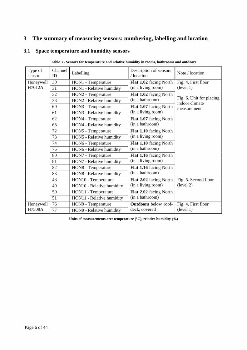
3 The summary of measuring sensors: numbering, labelling and location
3.1 Space temperature and humidity sensors
Table 3 - Sensors for temperature and relative humidity in rooms, bathrooms and outdoors
Type of sensor
Channel ID Labelling Description of sensors
/ location Note / location
Honeywell H7012A
30 HON1 - Temperature Flat 1.02 facing North (in a living room)
Fig. 4. First floor (level 1) Fig. 6. Unit for placing indoor climate measurement
31 HON1 - Relative humidity 32 HON2 - Temperature Flat 1.02 facing North
(in a bathroom) 33 HON2 - Relative humidity 60 HON3 - Temperature Flat 1.07 facing North
(in a living room) 61 HON3 - Relative humidity 62 HON4 - Temperature Flat 1.07 facing North
(in a bathroom) 63 HON4 - Relative humidity 72 HON5 - Temperature Flat 1.10 facing North
(in a living room) 73 HON5 - Relative humidity 74 HON6 - Temperature Flat 1.10 facing North
(in a bathroom) 75 HON6 - Relative humidity 80 HON7 - Temperature Flat 1.16 facing North
(in a living room) 81 HON7 - Relative humidity 82 HON8 - Temperature Flat 1.16 facing North
(in a bathroom) 83 HON8 - Relative humidity 48 HON10 - Temperature Flat 2.02 facing North
(in a living room) Fig. 5. Second floor (level 2)
49 HON10 - Relative humidity 50 HON11 - Temperature Flat 2.02 facing North
(in a bathroom) 51 HON11 - Relative humidity Honeywell H7508A
76 HON9 - Temperature Outdoors below roof-deck, covered
Fig. 4. First floor (level 1) 77 HON9 - Relative humidity
Units of measurements are: temperature (°C), relative humidity (%)

Page 7 of 44
3.2 CO2 sensors
Table 4 - Sensors for indoor CO2 concentration (in rooms)
Type of sensor
Channel ID Labelling Description of sensors
/ location Note / location
Vai
sala
CA
RB
OC
AP®
G
MW
20
23 CAR1 - CO2 Flat 1.02 facing North (in a living room) Error! Reference
source not found. Error! Reference source not found. Error! Reference source not found.
24 CAR2 - CO2 Flat 1.07 facing North (in a living room)
25 CAR3 - CO2 Flat 1.10 facing North (in a living room)
26 CAR4 - CO2 Flat 1.16 facing North (in a living room)
27 CAR5 - CO2 Flat 2.02 facing North (in a living room)
Units of measurements are: CO2 (ppm)
Note: Honeywell and CO2 sensors have the same location in the rooms.

Page 8 of 44
3.3 Opening & temperature sensors
Table 5 – Opening and temperature sensors
Type of sensor
Channel ID Labelling Description of sensors
/ location Note / location
Honeywell T7412A Magnetic valve DC101
28 TEW 1 Flat 1.02 V1(single window)
Error! Reference source not found. Error! Reference source not found. Error! Reference source not found.
29 OPW 1 30 TEW 2 Flat 1.02
V2(balcony windoor) 31 OPW 2 32 TEW 3 Flat 1.02
V3 (bath window) 33 OPW 3 34 TEW 4 Flat 1.02
D1 (entrance door) 35 OPW 4 36 TEW 5 Flat 1.07
V1(balcony windoor) 37 OPW 5 38 TEW 6 Flat 1.07
V2 (single window) 39 OPW 6 40 TEW 7 Flat 1.07
V3 (bath window) 41 OPW 7 42 TEW 8 Flat 1.07
D1 (entrance door) 43 OPW 8 44 TEW 9 Flat 2.02
V1(single window) 45 OPW 9 46 TEW 10 Flat 2.02
V2(balcony windoor) 47 OPW 10 48 TEW 11 Flat 2.02
V3 (bath window) 49 OPW 11 50 TEW 12 Flat 2.02
D1 (entrance door) 51 OPW 12
Units of measurements are: state of the window/door (close =0, open=1, time of opening/closing in seconds); temperature (°C)

Page 9 of 44
3.4 Built in sensors
Table 6 - Built-in sensors for temperature and humidity (in walls, floors, attic)
Type of sensor
Channel ID Labelling Description of sensors
/ location Note / location
Vaisala HMT100
0 DTU1 – Temperature
Unit facing North (module line 3-4)
Fig. 13. Detail 1 - sensor 1,2&3
1 DTU1 – Humidity 2 DTU2 – Temperature 3 DTU2 – Humidity 4 DTU3 – Temperature 5 DTU3 – Humidity 6 DTU4 – Temperature
Fig. 19. Detail 2 - sensor 4
7 DTU4 – Humidity
8 DTU5 – Temperature
Fig. 22. Detail 3 - sensor 5&6
9 DTU5 – Humidity 10 DTU6 – Temperature 11 DTU6 – Humidity 12 DTU7 – Temperature
Fig. 27. Detail 4 - sensor 7, 8 & 9
13 DTU7 – Humidity 14 DTU8 – Temperature 15 DTU8 – Humidity 16 DTU9 – Temperature 17 DTU9 – Humidity 18 DTU10 – Temperature
Ventilation shaft Fig. 32. Detail 5 - sensor 10 19 DTU10 – Humidity
20 DTU11 – Temperature Bathroom (module line 3-4)
Fig. 33. Detail 6 - sensor 11 21 DTU11 – Humidity
22 DTU12 – Temperature Room (module line 3-4)
Fig. 37. Detail 7 - sensor 12&13
23 DTU12 – Humidity 24 DTU13 – Temperature 25 DTU13 – Humidity 26 DTU14 – Temperature
Attic Fig. 40. Detail 8 - sensor 14&15
27 DTU14 – Humidity 28 DTU15 – Temperature 29 DTU15 – Humidity
Units of measurements are: temperature (°C) and relative humidity (%)

Page 10 of 44
3.5 Energy meters
Table 7 – List of energy meters
Type of sensor
Channel ID Labelling Description of
sensors / location Note / location
112 EM1- Solar energy
Solar output
Error! Reference source not found. 113 EM1- Solar flow
155 EM1 - Volume 156 EM1 - Temperature 1 157 EM1 - Temperature 2 114 EM2 - Solar Tank energy
From solar to accumulation tanks
115 EM2 - Solar Tank flow 159 EM2 - Volume 160 EM2 - Temperature 1 161 EM2 - Temperature 2 116 EM3 - Tank Hot energy
From tanks to DHW preheating
117 EM3 - Tank Hot flow 163 EM3 - Volume 164 EM3 - Temperature 1 165 EM3 - Temperature 2 118 EM4 - Hot water energy
DHW circulation energy
119 EM4 - Hot water flow 167 EM4 - Volume 168 EM4 - Temperature 1 169 EM4 - Temperature 2 120 EM5 - Circulation energy
DHW preheating by solar
121 EM5 - Circulation flow 171 EM5 - Volume 172 EM5 - Temperature 1 173 EM5 - Temperature 2 122 EM6 - Hot Heating energy
District heating to DHW
123 EM6 - Hot Heating flow 175 EM6 - Volume 176 EM6 - Temperature 1 177 EM6 - Temperature 2 124 EM7 - District energy
District heating total 125 EM7 - District flow 179 EM7 - Volume 180 EM7 - Temperature 1 181 EM7 - Temperature 2 126 EM8 - Tank Heating energy
From tanks to space heating
127 EM8 - Tank Heating flow 183 EM8 - Volume 184 EM8 - Temperature 1 185 EM8 - Temperature 2

Page 11 of 44
128 EM9 - Total energy
Total energy for space heating
129 EM9 - Total flow 187 EM9 - Volume
188 EM9 - Temperature 1 189 EM9 - Temperature 2 150 EM10 – HE 1 energy
Heating coil in ventilation unit VEX 1
151 EM10 – HE 1 flow 191 EM10 - Volume 192 EM10 - Temperature 1 193 EM10 - Temperature 2 152 EM11 – HE 2 energy
Heating coil in ventilation unit VEX 2
153 EM11 – HE 2 flow 195 EM11 - Volume
196 EM11 - Temperature 1 197 EM11 - Temperature 2
Units of measurements are: energy (kWh); flow (m3/h); volume (m3) and temperature (°C)
Page 12 of 44
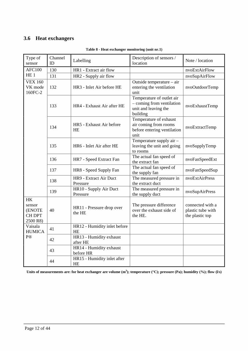
3.6 Heat exchangers
Table 8 - Heat exchanger monitoring (unit nr.1)
Type of sensor
Channel ID Labelling Description of sensors /
location Note / location
AFC100 HE 1
130 HR1 - Extract air flow nvoExtAirFlow 131 HR2 - Supply air flow nvoSupAirFlow
VEX 160 VK mode 160FC-2
132 HR3 - Inlet Air before HE Outside temperature – air entering the ventilation unit
nvoOutdoorTemp
133 HR4 - Exhaust Air after HE
Temperature of outlet air – coming from ventilation unit and leaving the building
nvoExhaustTemp
134 HR5 - Exhaust Air before HE
Temperature of exhaust air coming from rooms before entering ventilation unit
nvoExtractTemp
135 HR6 - Inlet Air after HE Temperature supply air – leaving the unit and going to rooms
nvoSupplyTemp
136 HR7 - Speed Extract Fan The actual fan speed of the extract fan nvoFanSpeedExt
137 HR8 - Speed Supply Fan The actual fan speed of the supply fan nvoFanSpeedSup
138 HR9 - Extract Air Duct Pressure
The measured pressure in the extract duct
nvoExtAirPress
139 HR10 - Supply Air Duct Pressure
The measured pressure in the supply duct nvoSupAirPress
HK sensor (ENOTECH DPT 2500 R8)
40 HR11 - Pressure drop over the HE
The pressure difference over the exhaust side of the HE.
connected with a plastic tube with the plastic top
Vaisala HUMICAP®
41 HR12 - Humidity inlet before HE
42 HR13 - Humidity exhaust after HE
43 HR14 - Humidity exhaust before HR
44 HR15 - Humidity inlet after HE
Units of measurements are: for heat exchanger are volume (m3); temperature (°C); pressure (Pa); humidity (%); flow (l/s)
Page 13 of 44
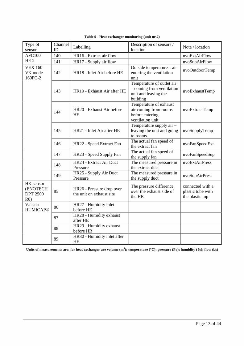
Table 9 - Heat exchanger monitoring (unit nr.2)
Type of sensor
Channel ID Labelling Description of sensors /
location Note / location
AFC100 HE 2
140 HR16 - Extract air flow nvoExtAirFlow 141 HR17 - Supply air flow nvoSupAirFlow
VEX 160 VK mode 160FC-2
142 HR18 - Inlet Air before HE Outside temperature – air entering the ventilation unit
nvoOutdoorTemp
143 HR19 - Exhaust Air after HE
Temperature of outlet air – coming from ventilation unit and leaving the building
nvoExhaustTemp
144 HR20 - Exhaust Air before HE
Temperature of exhaust air coming from rooms before entering ventilation unit
nvoExtractTemp
145 HR21 - Inlet Air after HE Temperature supply air – leaving the unit and going to rooms
nvoSupplyTemp
146 HR22 - Speed Extract Fan The actual fan speed of the extract fan nvoFanSpeedExt
147 HR23 - Speed Supply Fan The actual fan speed of the supply fan nvoFanSpeedSup
148 HR24 - Extract Air Duct Pressure
The measured pressure in the extract duct
nvoExtAirPress
149 HR25 - Supply Air Duct Pressure
The measured pressure in the supply duct nvoSupAirPress
HK sensor (ENOTECH DPT 2500 R8)
85 HR26 - Pressure drop over the unit on exhaust site
The pressure difference over the exhaust side of the HE.
connected with a plastic tube with the plastic top
Vaisala HUMICAP®
86 HR27 - Humidity inlet before HE
87 HR28 - Humidity exhaust after HE
88 HR29 - Humidity exhaust before HR
89 HR30 - Humidity inlet after HE
Units of measurements are: for heat exchanger are volume (m3); temperature (°C); pressure (Pa); humidity (%); flow (l/s)

Page 14 of 44
3.7 Other meters
Table 10 - Other sensors
Type of sensor
Channel ID Labelling Description of sensors /
location Note / location
109 EL2 - Electricity consumption – Cold water frost protection
110 EL1 – Total electricity consumption
Unit of measurements are: electricity (kWh)
Page 15 of 44
4 Details of sensors - description and location
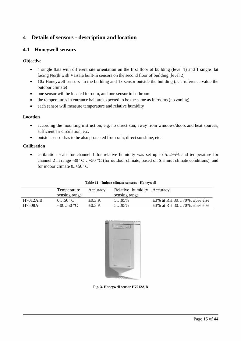
4.1 Honeywell sensors
Objective
• 4 single flats with different site orientation on the first floor of building (level 1) and 1 single flat facing North with Vaisala built-in sensors on the second floor of building (level 2)
• 10x Honeywell sensors in the building and 1x sensor outside the building (as a reference value the outdoor climate)
• one sensor will be located in room, and one sensor in bathroom • the temperatures in entrance hall are expected to be the same as in rooms (no zoning) • each sensor will measure temperature and relative humidity
Location
• according the mounting instruction, e.g. no direct sun, away from windows/doors and heat sources, sufficient air circulation, etc.
• outside sensor has to be also protected from rain, direct sunshine, etc.
Calibration
• calibration scale for channel 1 for relative humidity was set up to 5…95% and temperature for channel 2 in range -30 °C…+50 °C (for outdoor climate, based on Sisimiut climate conditions), and for indoor climate 0..+50 °C
Table 11 - Indoor climate sensors - Honeywell
Temperature sensing range
Accuracy Relative humidity sensing range
Accuracy
H7012A,B 0…50 °C ±0.3 K 5…95% ±3% at RH 30…70%, ±5% else H7508A -30…50 °C ±0.3 K 5…95% ±3% at RH 30…70%, ±5% else
Fig. 3. Honeywell sensor H7012A,B

Page 16 of 44
4.1.1 On floor level - layout
Level 1
Section Flat nr. Flat 1: 3-4 1.02 Flat 2: 8-9 1.07 Flat 3: 14-15 1.10 Flat 4: 20-21 1.16
Fig. 4. First floor (level 1)
Page 17 of 44
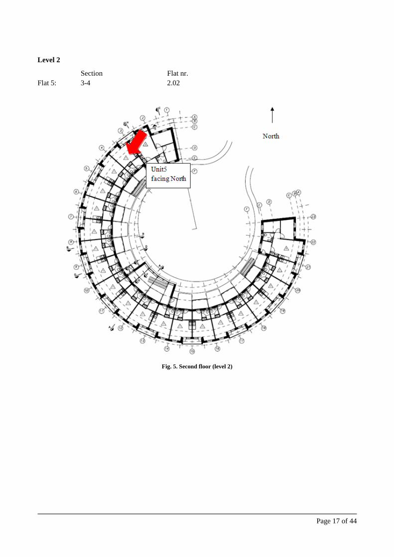
Level 2
Section Flat nr. Flat 5: 3-4 2.02
Fig. 5. Second floor (level 2)

Page 18 of 44
4.1.2 On room level - single unit
Fig. 6. Unit for placing indoor climate measurement
4.2 CO2 sensors
Objective
• to register the level of CO2 concentration • Vaisala CARBOCAP® Carbon Dioxide Transmitter Series GMW20 (wall mounted) with no display
Location
• as for indoor climate Honeywell sensors in living rooms • wall mounted (GMW)
Calibration
• before delivery: 0…5,000 ppm • after 5 years

Page 19 of 44
Fig. 7. CO2 transmitter for demand
4.3 Opening and temperature sensors
Objective
• in 3 single units • two sensors will be located in room, one sensor in bathroom and one in entrance • each sensor will measure the state of opening of a window / door (0=closed, 1=open) and time
duration (in seconds) • each sensor will be accompanied with a temperature sensor
Location
• according the mounting instruction • balcony door (right side) and single window in a room, bathroom window, entrance door
Calibration
• not needed
Fig. 8. Magnetic valve DC101

Page 20 of 44
4.4 Build in sensors
Objective
• to measure moisture content in construction • in most demanding places • to measure varying content of moisture (leads to shrinking or swelling of wood) or high moisture
content (growth of mould, fungi) • built-in moisture and moisture transfer from in/out • cheap yet reliable sensors • timber structure with insulation with concrete load bearing structure and steel additional structure • the protection cap will be from steel
Location
• biggest risk of condensation • location close to outside of the insulation are worse (better to measure) • North orientation is more critical than South orientation • position with moisture sensible materials (e.g. wood or other organic materials) are more important
to measure than positions with less sensible materials (e.g. concrete) • positions around cold bridges might be interesting, but also positions away from cold bridges • potential cold spots are probably more interesting than potential warm spots • positions where there is a risk that there could be an air flow, e.g. risk that warm humid air from
inside could penetrate and pass by • steel structure holding the solar collectors (top of concrete/below insulation) • between concrete and roof insulation away from the structure that holds the solar collectors
Calibration
• calibrated according the best usage in Arctic climate • if the temperature goes below -40 °C, the sensor will log a value “-40 °C”; when the temperature rise
over -40 °C the actual value will be shown • calibration scale for channel 1 (temperature) -40 °C to +40 °C (0...10 V) and for channel 2
(humidity) 0..100%
Table 12
Moisture and temperature built-in sensors - Vaisala
Temperature measurement range
Accuracy Relative humidity sensing range
Accuracy
HMT100 -40 …+80 °C ±0.2 at 20 °C 0…100% <2.5% RH dependent on temp.

Page 21 of 44
Fig. 9. Vaisala HMT100 remote probe with wall mount model
Table 13
List of sensors and why they are placed in a location
Detail 1 DTU1 – Temperature & Relative humidity
To log temperature in critical place between inside gypsum and concrete wall. Could point out an air-tight problem.
DTU2 – Temperature & Relative humidity
Critical place between concrete and insulation. Could show problem of condensation influenced from outside temperature and interior concrete.
DTU3- Temperature & Relative humidity
Temperature and RH on almost exterior surface. Sensors in detail1 are facing North.
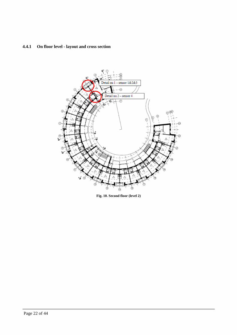
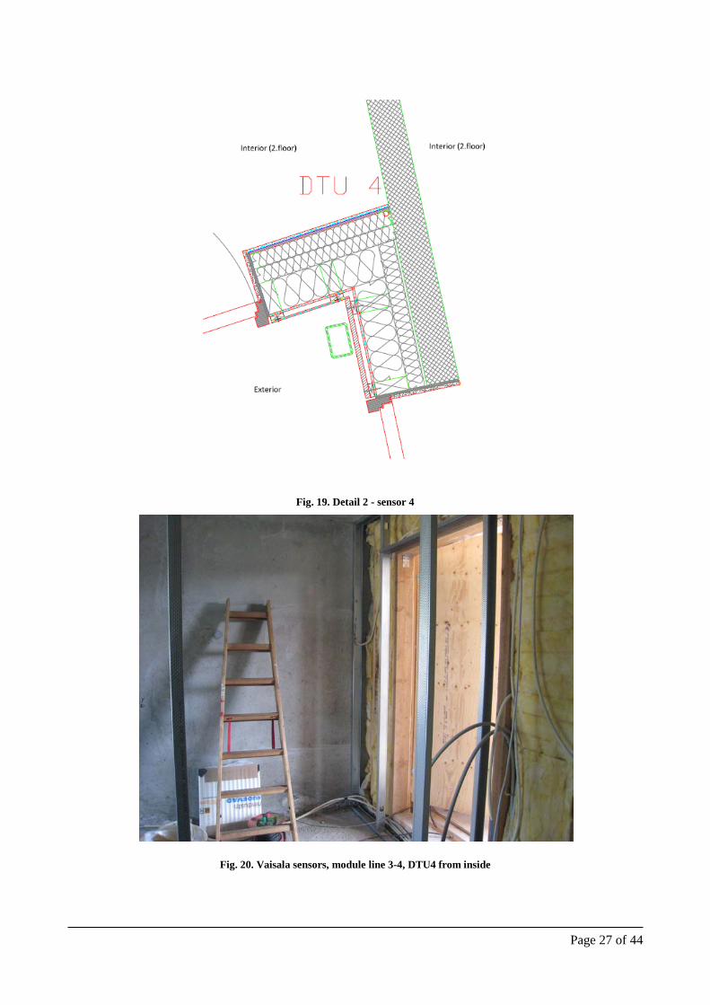
Detail 2 DTU4 – Temperature & Relative humidity
Temperature and RH close to internal surface. Could show a problem with condensation. Sensor is facing closed circle of dormitory.
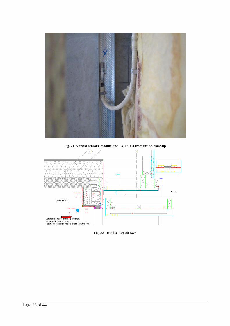
Detail 3 DTU5 – Temperature & Relative humidity
Risk of condensation on inner surface in window corner. Located on second floor and facing North.
DTU6 – Temperature & Relative humidity
Measurement of almost outside surface of construction. Facing North and on second floor close to ceiling.
Detail 3 DTU7 – Temperature & Relative humidity
Measurement of temperature on inner face of concrete, possible risk of condensation of air coming from outside and touching of concrete. Mould growth.
DTU8 – Temperature & Relative humidity
Connection between suspended balcony and concrete-load bearing structure. Possible transfer of heat to the building.
DTU9 – Temperature & Relative humidity
Possible transfer of heat from outside to inside beneath a wooden detail below window. Facing North and between first and second floor.
Detail 5 DTU10 – Temperature & Relative humidity
Temperature and RH in shaft were the ducts for ventilation are placed.
Detail 6 DTU11 – Temperature & Relative humidity
Difficult place close to outside temperature, transfer of heat. Facing closed circle of Dormitory.
Detail 7 DTU12 - 13 – Temperature & Relative humidity
Typical detail of small window facing North. Transfer heat in detail of window mounting.
Detail 8 DTU14 – Temperature & Relative humidity
Protruding of steel structure holding solar support. Possible risk of condensation and cold bridge.
DTU15 – Temperature & Relative humidity
Temperature and RH of attic, close to outside.
Page 22 of 44
4.4.1 On floor level - layout and cross section
Fig. 10. Second floor (level 2)

Page 23 of 44
Fig. 11. Cross-section I (module line 3-4)
Fig. 12. Cross section II (module line 3-4)

Page 24 of 44
4.4.2 On room level - walls, floors, attic
Fig. 13. Detail 1 - sensor 1,2&3
Fig. 14. Vaisala sensors, module line 3-4, DTU1 and DTU2, from inside

Page 25 of 44
Fig. 15. Vaisala sensors, module line 3-4, DTU1, from inside
Fig. 16. Vaisala sensors, module line 3-4, DTU2, from inside

Page 26 of 44
Fig. 17. Vaisala sensors, module line 3-4, DTU3 and DTU8 from outside
Fig. 18. Vaisala sensors, module line 3-4, DTU3 from outside
Page 27 of 44
Fig. 19. Detail 2 - sensor 4
Fig. 20. Vaisala sensors, module line 3-4, DTU4 from inside
Page 28 of 44
Fig. 21. Vaisala sensors, module line 3-4, DTU4 from inside, close-up
Fig. 22. Detail 3 - sensor 5&6

Page 29 of 44
Fig. 23. Vaisala sensors, module line 3-4, DTU5 and DTU6 from inside
Fig. 24. Vaisala sensors, module line 3-4, DTU5 from inside, close-up

Page 30 of 44
Fig. 25. Vaisala sensors, module line 3-4, DTU6 from inside
Fig. 26. Vaisala sensors, module line 3-4, DTU6 from inside, close-up

Page 31 of 44
Fig. 27. Detail 4 - sensor 7, 8 & 9
Fig. 28. Vaisala sensors, module line 3-4, DTU3 (left) and DTU8 (right), from outside

Page 32 of 44
Fig. 29. Vaisala sensors, module line 3-4, DTU8 from outside, close-up
Fig. 30. Vaisala sensors, module line 3-4, DTU9 from inside

Page 33 of 44
Fig. 31. Vaisala sensors, module line 3-4, DTU9 from inside, close-up
Fig. 32. Detail 5 - sensor 10

Page 34 of 44
Fig. 33. Detail 6 - sensor 11
Fig. 34. Vaisala sensors, module line 3-4, DTU11 from inside

Page 35 of 44
Fig. 35. Vaisala sensors, module line 3-4, DTU11 from inside, close-up
Fig. 36. Vaisala sensors, module line 3-4, DTU11 from inside, close-up 2

Page 36 of 44
Fig. 37. Detail 7 - sensor 12&13
Fig. 38. Vaisala sensors, module line 3-4, DTU12 (back) and DTU13 (front) from inside

Page 37 of 44
Fig. 39. Vaisala sensors, module line 3-4, DTU12 (back) and DTU13 (front) from inside, close-up
Fig. 40. Detail 8 - sensor 14&15

Page 38 of 44
4.5 Energy meters
Objective
• to measure various consumptions and flows, and be able to measure/calculate the total heating consumption
• identify the heat loss in case of circumpolar heat loss or escape of energy • Kamstrup Multical 601 based on the diameter of the ducts and on the flow
Location
• According to drawing in Fig. 42.
Calibration
• Calibrated from factory
Fig. 41. Energy meter Kamstrup Multical 601

Page 39 of 44
Fig. 42. Technical room scheme and energy meter placement

Page 40 of 44
4.6 Ventilation
Objective
• Evaluation of ventilation unit’s performance • IAQ measurements
Location
• Inside the ventilation units
Calibration
• Calibrated from manufacturer
4.6.1 AFC100
• to measure the air flow from extract and supply air
Fig. 43. AFC100 for heat exchanger
4.6.2 VEX 160FC
• delivered with VEX • to measure: inlet air before HE, exhaust air after HE, exhaust air before HE, inlet air after HE, speed
of extract and supply fan, pressure of extract and supply air duct • description in file
4.6.3 HK sensors
• to measure pressure loss of / over the unit, where air flow is measured based on the pressure difference
• to monitor what is the pressure difference on exhaust before and after the unit, to be able to see if the pressure loss of unit increases when there is freezing of a unit

Page 41 of 44
Fig. 44. Location of HK sensors
4.6.4 Humidity sensors
• to monitor the relative humidity of: inlet before HE, exhaust after HE, exhaust before HR and inlet after HE
Fig. 45. Vaisala Humicap HMT100 with duct installation mounting kit

Page 42 of 44
5 Contact list
5.1 Monitoring system
Name Contact information Position in the project
Petra Vladykova
Ph.D. student
Technical University of Denmark
Brovej 118, 2800 Kgs. Lyngby, Denmark
+45 45 25 18 62
+45 60 83 21 55
www.dtu.dk
Design of the monitoring system and selection of sensors
Martin Kotol
Ph.D. student
Technical University of Denmark
Brovej 118, 2800 Kgs. Lyngby, Denmark
System operation, data analysis, trouble shooting, building experiments
Stefan Hammer
Electricity Installer
Kaataq El ApS,
Aqqusinersuaq 81, Postboks 465, 3911 Sisimiut, Greenland
+299 86 56 86
www.kaataqel.gl
Installation and selection of sensors
Setting up of Lonbox system
Martin Gredsted
Building site supervisor
(Projektleder)
TNT NUUK
+299 48 74 01
Building site manager for Apisseq

Page 43 of 44
5.2 Sensors
Name Contact information Position in the project
Jan Olsen
Brdr. Jørgensen Instruments A/S
Hanne Nielsens Vej 10, 2840 Holte
+45 45 47 30 44
www.brj.dk
Ordering, calibration and delivery of Vaisala sensors
Anders Møller
Automatikcentret ApS
Strandvejen 42, Saksild, 8300 Odder
+45 86 62 63 64
Ordering and delivery of Honeywell sensors
Thomas Maltesen Prolon A/S Denmark, www.prolon.dk [email protected]
Provider of PID 4000
Jesper Gram Hansen Servicechef
EXHAUSTO DK
Odensevej 76 DK-5550 Langeskov www.exhausto.dk [email protected]
Provider of ventilation unit VEX160
Gabi
Lars Løvendahl
Broendum
+299 525913
Supplier and mounting of EM 4-9 for heating system
Lars Weiss VVS Service Sisimiut A/S
Box 237
3911 Sisimiut
+299 864924
Supplier and mounting of EM 1,2,3 for solar heating
Page 44 of 44
5.3 Technical University of Denmark
Name Contact information Position in the project
Arne Villumsen [email protected] Project supervisor for monitoring system
Carsten Rode [email protected] Decision making and advice on the monitoring system
Simon Furbo [email protected] Solar system monitoring advisor
Janne Dragsted Solar system monitoring advisor
5.4 Dormitory
Name Contact information Position in the project
Jørn Hansen
Akademiingeniør
Rambøll, Sisimiut afd. Postboks 426, 3911 Sisimiut, Grønland [email protected]
Involved in dormitory Representative from the employer (building owner)
Sten Kryger Andersen
Architect, Engineer
Inuplan A/S
Postbox 1024, 3900 Nuuk +299 34 37 01
Design of the dormitory
Energy calculation
Robert Sundquist
Exoheat [email protected] +46 (0) 43 17 89 90
Design of heating system
Flemming Berger
TNT Nuuk
+299 32 12 56
Project team leader
Ole Lennert
SARFAA Ingengeniørit siunnersuisartut. Postboks 561, Saqqarlernut 28, 3900 Nuuk
[email protected] +299 34 81 00
Member of project team Data Acquisition Equipment
Peter Poulsen
TNT Nuuk a/s
Hellerupvej 8, baghuset, 2900 Hellerup
Design of Apisseq Architectural expression