
Monitoring Reciprocating Compressors Reciprocating Compressors... · Monitoring Reciprocating...
50
Monitoring Reciprocating Compressors for the Vibration Institute Piedmont Chapter September 18th
Transcript of Monitoring Reciprocating Compressors Reciprocating Compressors... · Monitoring Reciprocating...
Monitoring Reciprocating
Compressors
for the Vibration Institute
Piedmont Chapter
September 18th

Mary Margaret Chapman
• Degree in Computer Science from the University of Tennessee
• Worked for CSI 1988 to 1996
• Worked for MachineXpert 1996 – 2002
• Worked for PCB Piezotronics 2002 – End 2012
• Worked for Windrock Beginning of 2013 to Present

What is a Reciprocating machine?
A reciprocating machine is one
which rotational movement is turned
into reciprocating motion
This is normally done with the use of
a crankshaft, connecting rod and
crosshead or piston

FFT Monitoring for Rotating Equipment
• Components that PdM personal use to get FFT data:
- Accelerometer
- Cable
- Data Collector
Vibration
measured as a
function of time
but also as a
function of
frequency or phase

FFT Example on a reciprocating Compressor
Normal Horizontal and Axial readings on end of cylinder
Lots of energy related to running speed could make it hard to determine
issues

Vibration on the cross head of a compressor
Throw
• An Example of the limitations of Waveform/FFT analysis on a
reciprocating compressor
You Know something is wrong but what is the problem? Stay tune till the end of the
presentation to find out.

Portable Reciprocating Monitoring Tool
• A Predictive Tool
- Reciprocating Machinery Analysis
- Engines
- Compressors
- Data Typically Collected
- In Cylinder Pressure
- Temperatures
- Vibration
- Ultrasonics
7

Key Component of Crank Angle Analysis
• Pressure, Vibration, Ultrasonic Data is referenced to crank shaft
position
- This is Not FFT or Spectrum Data Vibration Data
- Band Filtered, Envelope Detected Vibration
- Frequency Ranges specific to Reciprocating machines
• Cylinder Top Dead Center (TDC) Synchronized to Analyzer

Crank Angle Vibration on Compressor

Performance data on Compressors
• Horsepower
• Volumetric efficiency (suction and discharge)
• Flow
• Leak Index & Flow balance
• Valve/nozzle HP loss – suction and discharge
• Clearance volume
• Toe pressures
• Theoretical vs. actual discharge temperature
• Rod load – compression and tension
• Rod reversal

Mechanical defects on Compressors
• Vibration vs. Crankangle
- Loose rod on piston/crosshead – by looking at the vibration
pattern vs. rod load, you can zero in on the cause.
- Abnormal impacts on valves, unloading devices
- Crosshead looseness
- Bearing defects
• FFT Vibration
- Coupling misalignment
- Imbalance
- Foundation problems
- Pulsation problems
- Broken frame bolting

Common Problems picked up with portable
• Engines
- Valve Leakage
- Valve Train Problems
- Ignition Issues
- External leaks
- Piston / Cylinder Issues
- Bearings
- Accessories like Oil Pump, Water Pump
12
• Compressor
- Suction/Discharge Valve
- Leaking Valves
- Leaking Rings
- Malfunctioned Unloaders
- Rod Load / Rod Reversal
- Snap shot in time
- Load / Flow
- Vibration Issues
- Pulsation
- Rider Band / Cross Head Wear

Benefits of monitoring reciprocating compressors
• Defer Calendar Based
Maintenance
• Performance Optimization
• Machinery Throughput
Improvement
• Avoid Catastrophic Failures
• Reduce unscheduled downtime
• Reduce Machinery Abuse
• Quality Assurance of the New
Installations and Overhaul
Equipment
• Planning and Scheduling
• Extend the run time between
overhauls
• Prioritize Maintenance
Expenditures
Profit = Totalized throughput – (Energy cost +
Maintenance Cost + Operating Cost + Analyzer
Department Cost)

TDC Reference
• Shaft encoder
• Magnetic pickup
• Phased data
• RPM Suction/discharge temperatures
• Infrared temperature wand
• thermocouples, RTDs
Head/crank end pressure
• Pressure transducer
• Time domain data phased to crankshaft
position
• Multi-period sampling statistics
Suction/discharge valve vibration
Compressor ring leak vibration
Liner scoring
• Ultrasonic microphone
• Standard accelerometer
• Time domain data phased to crankshaft
position
Frame vibration (displacement)
• Tri-axial accelerometer (H, V, A) taken
at opposite corners of engine frae
• Frequency domain data
Rod Motion
• Proximity probes
• Time-domain data phased to
crankshaft position
• Rod displacement trends
Suction/discharge nozzle pressure
• Pressure transducer
• Time domain data phased to crankshaft position
(valve/passage loss calculations)
• Frequency domain (pulsation spectrum)
• Multi-period sampling statistics
Valve cap temperatures
• Infrared temperature wand
Crosshead Vibration
• Standard accelerometer
• Time domain data phased to
crankshaft position
• Relate to rod load
Compressor Data

Pressure Readings

Head and Crank End Pressure Sensors
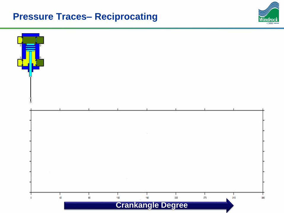
Pressure Traces– Reciprocating
Crankangle Degree

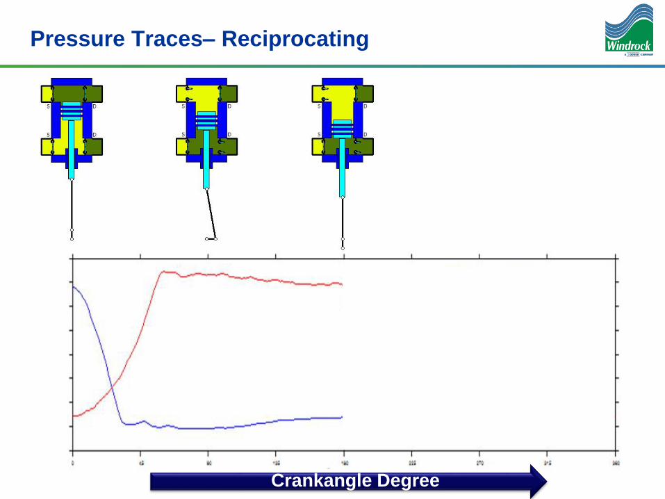
Pressure Traces– Reciprocating
Crankangle Degree
Pressure Traces– Reciprocating
Crankangle Degree

Pressure Traces– Reciprocating
Crankangle Degree

Pressure Traces– Reciprocating
Crankangle Degree

Pressure Volume Curves
22
Expansion
Suction
Compression
Discharge

Suction Valve Leakage

Discharge Valve Leakage

Repaired Discharge Valve
Before
After Valve

Calculating Horsepower
26
It takes work to transport gas through a pipe
That work is the area inside the PV curve
The rate of doing work is horsepower
IHP = Work * Speed
And the work is the area
inside the PV curve

Calculate Power Losses?
Why is this
important?
By reducing
valve losses you
reduce Horse
Power needed to
flow gas. Less
fuel / amps

Valve Losses on C2001 B

Dynamic Load - Combined
Static + Inertial = Dynamic ( Total ) Rod LoadMost of the time, inertial load reduces peaks of total load.

Within Rod Load Limits

Exceeding Rod Load

Vibration to
Identify
Mechanical
Defects

TIME
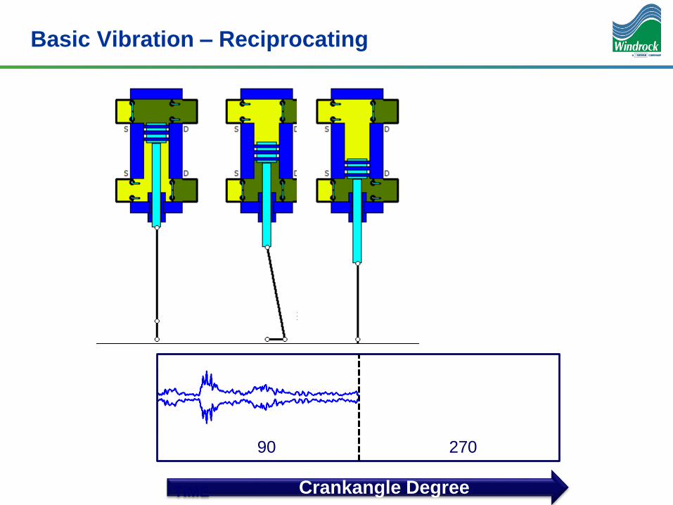
Basic Vibration – Reciprocating
Crankangle Degree
90 270
Vibration is taken in conjunction
With an encoder or mag pickup.

TIME
Basic Vibration – Reciprocating
90 270
Crankangle Degree
TIME
Basic Vibration – Reciprocating
90 270
Crankangle Degree

TIME
Basic Vibration – Reciprocating
90 270
Crankangle Degree

TIME
Basic Vibration – Reciprocating
90 270
Crankangle Degree

Crosshead Knock
• Vibrations are easily traced to cause. Below a crosshead knock
occurs at force reversal.

Worn Out Rider Rings

UltraSonics to
Identify
Mechanical
Defects

Discharge Leak – shown in Ultrasonic data
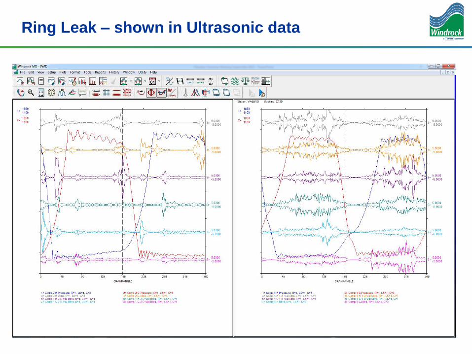
Ring Leak – shown in Ultrasonic data

Remember the
Spectrum and
Waveform data
from the beginning
of the
presentation?

Back to our example from the beginning
• Since we know something is different, but can not determine what it is with FFT – lets
look at the crank angle data.

Pressure Trace
May 21st June 13th
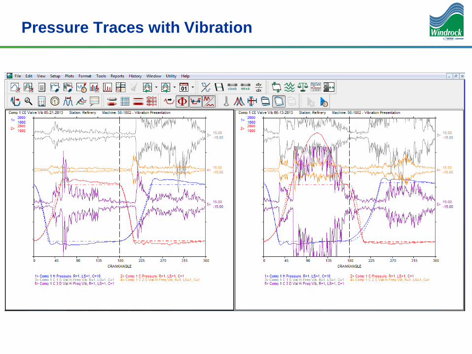
Pressure Traces with Vibration

Ultra Sonics Traces with Vibration
Plugged Valves Due to Worn Riders

Vibration on the head end of a compressor Throw
Valve Opening Impact
No Clean Impact – Higher vibration while
trying to push gas through

Conclusion
• Where Spectrum vibration data is
the most valuable on rotating
equipment
Value of Analysis Tools for Rotating Equipment
Spectrum Time Waveform Temperatures
Value of Analysis Tools forReciprocating Equipment
Crankangle Pressure Crankangle Ultrasonic
Crankangle Vibration Temperature
• Crank angle data is most
valuable on reciprocating
equipment

Question?
•Slicing up the PIE for
Analysis Tools
-Spectrum Data for
Rotating Equipment
-Crank-angle Data for
Reciprocating
Equipment