M•ONE & M•ONE XL
46
M•ONE & M•ONE XL DUAL EFFECTS PROCESSORS USER’S MANUAL
Transcript of M•ONE & M•ONE XL

M•ONE &M•ONE XLDUAL EFFECTS PROCESSORS
UUSSEERR’’SS MMAANNUUAALL


IMPORTANT SAFETY INSTRUCTIONS
1 Read these instructions.2 Keep these instructions.3 Heed all warnings.4 Follow all instructions.5 Do not use this apparatus near water.6 Clean only with dry cloth.7 Do not block any ventilation openings.
Install in accordance with themanufacturer's instructions.
8 Do not install near any heat sources such as radiators, heat registers, stoves, or otherapparatus (including amplifiers) thatproduce heat.
9 Do not defeat the safety purpose of the polarized or grounding-type plug. Apolarized plug has two blades with one wider than the other. A grounding type plug has two blades and a third grounding prong. The wide blade or the third prong are provided for your safety. If the provided plug does not fit into your outlet, consult anelectrician for replacement of the obsolete outlet.
10 Protect the power cord from being walked on or pinched particularly at plugs, convenience receptacles, and the point where they exit from the apparatus.
11 Only use attachments/accessories specified by the manufacturer.
12 Unplug this apparatus during lightning storms or when unused for long periods of time.
13 Refer all servicing to qualified service personnel. Servicing is required when the apparatus has been damaged in any way, such as power-supply cord or plug is damaged, liquid has been spilled or objectshave fallen into the apparatus, the apparatus has been exposed to rain or moisture, does not operate normally, or hasbeen dropped.
• This equipment should be installed near thesocket outlet and disconnection of the device should be easily accessible.
• Do not install in a confined space.• Do not open the unit - risk of electric shock
inside.
Caution:You are cautioned that any change ormodifications not expressly approved in thismanual could void your authority to operate thisequipment.
Service• There are no user-serviceable parts inside. • All service must be performed by qualified
personnel.
Warning!• To reduce the risk of fire or electric shock,
do not expose this apparatus to rain or moisture.
• This apparatus must be earthed.• Use a three wire grounding type line cord
like the one supplied with the product.• Be advised that different operating voltages
require the use of different types of line cord and attachment plugs.
• Check the voltage in your area and use the correct type. See table below:
Voltage Line plug according to standard110-125V UL817 and CSA C22.2 no 42.220-230V CEE 7 page VII, SR section
107-2-D1/IEC 83 page C4.240V BS 1363 of 1984.
Specification for 13A fused plugs and switched and unswitched socket outlets.
The lightning flash with an arrowheadsymbol within an equilateral triangle, isintended to alert the user to the
presence of uninsulated "dangerous voltage"within the product's enclosure that may be ofsufficient magnitude to constitute a risk of electric shock to persons.
The exclamation point within anequilateral triangle is intended to alertthe user to the presence of important
operating and maintenance (servicing)instructions in the literature accompanying theproduct.
a

IMPORTANT SAFETY INSTRUCTIONS
Certificate Of ConformityTC Electronic A/S, Sindalsvej 34, 8240Risskov, Denmark, hereby declares on ownresponsibility that following products:
M•ONE - Dual Effects Processor &M•ONE XL - Dual Effects Processor
- that is covered by this certificate andmarked with CE-label conforms withfollowing standards:
EN 60065 Safety requirements for mains (IEC 60065) operated electronic and
related apparatus for householdand similar general use
EN 55103-1 Product family standard for audio,video, audio-visual and entertainment lighting control apparatus for professional use. Part 1: Emission.
EN 55103-2 Product family standard for audio, video, audio-visual andentertainment lighting control apparatus for professional use. Part 2: Immunity.
With reference to regulations in followingdirectives:73/23/EEC, 89/336/EEC
Issued in Risskov, 09 2001Anders Fauerskov
Chief Executive Officer
EMC / EMI.This equipment has been tested and found tocomply with the limits for a Class B Digitaldevice, pursuant to part 15 of the FCC rules.These limits are designed to providereasonable protection against harmfulinterference in residential installations. Thisequipment generates, uses and can radiateradio frequency energy and, if not installed andused in accordance with the instructions, maycause harmful interference to radiocommunications. However, there is noguarantee that interference will not occur in aparticular installation. If this equipment doescause harmful interference to radio or televisionreception, which can be determined by turningthe equipment off and on. The user isencouraged to try to correct the interference byone or more of the following measures:
• Reorient or relocate the receiving antenna.• Increase the separation between the
equipment and receiver.• Connect the equipment into an outlet on a
circuit different from that to which the receiver is connected.
• Consult the dealer or an experienced radio/TV technician for help.
For the customers in Canada:This Class B digital apparatus complies withCanadian ICES-003.Cet appareil numérique de la classe B estconforme à la norme NMB-003 du Canada.
b

3
TABLE OF CONTENTS
INTRODUCTION
Important Safety InstructionsTable of contents . . . . . . . . . . . . . . . .3Introduction . . . . . . . . . . . . . . . . . . . . .5Front Panel . . . . . . . . . . . . . . . . . . . . .6Rear Panel . . . . . . . . . . . . . . . . . . . . .8Signal flow diagram &Soldering Instructions . . . . . . . . . . . . .9
BASIC OPERATION
The M•ONE Display . . . . . . . . . . . . .10I/O Setup . . . . . . . . . . . . . . . . . . . . .11Clock Mismatch . . . . . . . . . . . . . . . . .11Utility & MIDI . . . . . . . . . . . . . . . . . . .12Routings . . . . . . . . . . . . . . . . . . . . . .13Recall . . . . . . . . . . . . . . . . . . . . . . . .16Edit . . . . . . . . . . . . . . . . . . . . . . . . . .16Store . . . . . . . . . . . . . . . . . . . . . . . . .17Tap . . . . . . . . . . . . . . . . . . . . . . . . .17
ALGORITHMS
ReverbHall . . . . . . . . . . . . . . . . . . . . . . . . . .18Room . . . . . . . . . . . . . . . . . . . . . . . .19Small Room . . . . . . . . . . . . . . . . . . .21Plate 1 . . . . . . . . . . . . . . . . . . . . . . .22Plate 2 . . . . . . . . . . . . . . . . . . . . . . .23Spring . . . . . . . . . . . . . . . . . . . . . . . .24Live . . . . . . . . . . . . . . . . . . . . . . . . .25Ambience . . . . . . . . . . . . . . . . . . . . .26
Other AlgorithmsDelay - One Tap & two Tap . . . . . . . .27Delay - PingPong . . . . . . . . . . . . . . .28Chorus - Classic & 4-Voice . . . . . . . .29Flange - Classic & 4-Voice . . . . . . . .30Pitch - Detune & Pitch Shift . . . . . . . .31Parametric Equalizer . . . . . . . . . . . . .32Compressor & Limiter . . . . . . . . . . . .33Gate/Expander . . . . . . . . . . . . . . . . .34De-esser . . . . . . . . . . . . . . . . . . . . . .35Tremolo - Hard & Soft . . . . . . . . . . . .36Phaser - Vintage & Smooth . . . . . . . .37
APPENDIX
MIDI Implementation Chart . . . . . . . .38Technical Specifications . . . . . . . . . .39Troubleshooting . . . . . . . . . . . . . . . .41Preset List . . . . . . . . . . . . . . . . . . . .42
TC Electronic, Sindalsvej 34, DK-8240 Risskov - [email protected] English version Prod. No: E60500152
Rev 4 - SW - V 1.43 - STRev 4 - SW - V 2.07 - XL


INTRODUCTION
Congratulations on the purchase of your new TC Electronic M•ONE or M•ONE XL unit. The M•ONE is a Dual Engine Multi-effects Processor, focusing mainly on high quality Reverbs. TheM•ONE can be used for a number of purposes due to flexible routing of the two Engines and morethan 20 TC algorithms. Do you want two independent Reverbs, controlled from separate Auxiliarysends? Select the Dual Input Routing plus two Reverbs, and you are up and running. Do you wanta compressor in front of a Delay? Select the Serial Routing, a Compressor and a Delay. You caneven tap the Delay time on the TAP key. Or maybe you just want stick with that one Routing, nomatter the preset? Simply use the Routing Lock function to avoid routing changes at preset change.It is really as easy as that, go ahead and tweak some keys and knobs. We hope you have as muchpleasure using the M•ONE as we had making it.
Please note that this manual covers both the M•One and the M•One XL. Both products will ingeneral be referred to as “M•One”. When a feature relevant only for the XL version iscovered, this will be marked with “XL only”.
• Hall
• Room
• Small Room(XL only)
• Plates 1&2
• Spring
• Live
• Ambience
• Delay One Tap
• Delay Two Tap
• PingPong Delay(XL only)
• Chorus Classic & 4-voice
• Flange: Classic & 4-voice
• Pitch: Detune & Pitch Shift
• Parametric EQ
• Compressor/Limiter
• Gate/Expander
• De-esser
• Tremolo
• Phaser
Though the M•ONE is focusing on high quality Reverb you will discover that theM•ONE also covers a wide variety of other algorithms. Experience and enjoy !
5

6
FRONT PANEL
POWER buttonPower on/off.
IN LEVEL knobAdjusts the Input level. At center position a relay willswitch the Input circuitbetween consumer and prolevel. This will insure optimalInput gain range and superb“signal to noise” ratio isachieved.
MIX knobAdjusts the global mix betweendry and wet signal.Fully clockwise is 100% effect.
EFFECT BAL knobAdjusts the balance betweenthe two Engines.
INPUT MetersThe Peak meter shows theInput level of left/rightchannels. The meter range is: 0, -3, -6 ,-12, -18, -24, -40.
OVERLOAD LEDsThe OVERLOAD LEDsindicate one of two situations: • The Input level is too hot
and therefore overloading.• There is an internal DSP
overflow. The Overload LED is lit when 1 sample is @ -1dBFS.
INPUT - Analog/DigitalIndicates whether the M•ONEis set to analog or digital Input.When set to digital Input, theSample Rate automaticallyswitches to DI. In case of no or unacceptableclock the "Digital" and "DI" iconwill be blinking.
ANALOG/DIGITAL LEDANALOG/DIGITAL indicator states the selected Input. Input type is selected in the "I/O Setup" menu.
SAMPLE RATE indicatorThe SAMPLE RATE indicatorshows the clock source andthe incoming master clock.The “Digital In” icon will beblinking if no clock orunacceptable clock is found.
ROUTING indicatorIndication of what Routingmode the M•ONE currently isusing.
ALGO IndicatorShows the currently used algorithms in each of the twoEngines.
DYNAMIC meters 1+2These two meters show thegain reduction when an Engineis running Dynamic algorithms.The Dynamic algorithms are:Compressor, Limiter, Gate,Expander and De-esser.
DISPLAYDisplays the preset numberand the preset type: Factory or User.
EDITED iconThis icon will be lit as soon asthe current recalled preset hasbeen modified.
FACTORY/USER iconShows whether you are operating in the Factory or theUser bank.
MIDI IN iconShows any incoming MIDI activity.

7
FRONT PANEL
ROUTING keyPress the ROUTING key to setthe Engine Routing. The options are: Dual Send/Ret, Parallel, Parallel/Serial,Serial, Stereo, Dual Mono.
I/O SETUPBasic parameters are set here.• Input source - Analog/Digital.• Sample Rate -
44.1/48kHz/DI• Bypass Mode - See Bypass
keys 1 and 2.• Global Output level.• Dither 16, 20 or 24(off).
TAP keyTap this key to enter the globalTap tempo and to enter theTap menu. Subdivision of thetapped tempo is setup in thismenu. The tapped tempo canbe used for Delay time, Chorusrate etc.
UTILITYMIDI, Sys-Ex ID, Routing-lock,Bypass mode, Pedal functionand Display View angle.
ALGO/EDIT 1+2Press this key to enter the Editdisplay and the AlgorithmChange display of the currentlyselected Engine.
BYPASS keys 1 and 2The Bypass mode is set up inUtility. There are three differentBypass modes:
1 0% Mix: The Input signal is passed directly to the Output.
2 FX Input: Cuts only the Engine Input in order to let the effect "ringout", but will still leave thesame amount of dry signalcoming through.
3 FX Output: Cuts only the Engine Outputin order to kill the FX instan-taneously, but leaves thesame amount of dry signalcoming through.
RECALL keySelects the Recall menu.Select a desired preset usingthe CONTROL wheel andpress the ENTER key toenter/load the selected preset.
STORE keySelects the Store menu.Presets can be stored in theUser bank only. Location isselected using the CONTROLwheel. Operation is confirmedusing ENTER.
CURSOR UP/DOWNUse the cursors to movearound in the display.
ENTER keyConfirms operations. TheENTER key LED will indicatewhen this key can be used.
EXIT keyIs used to exit a menu or to disapprove an action.
CONTROL wheelIs used to change values.

8
REAR PANEL
IN
UL6500EN/IEC 60065
PROFESSIONAL AUDIO EQUIPMENT
THRUINLEFT LEFTRIGHT RIGHT OUTMIDIBALANCED INPUTS BALANCED OUTPUTS DIGITAL I/O PEDAL
DI
DO
S/PDIF
SERIAL NO.
TYPE: MAN001
TC ELECTRONIC
MADE IN THAILANDWARNINGTO REDUCE THE RISK OF FIRE OR ELECTRIC
SHOCK DO NOT EXPOSE THIS EQUIPMENT TO
RAIN OR MOISTURE
AVIS: RISQUE DE CHOC ELECTRIQUE-NE PAS
OUVRIR.
100-240VAC50-60Hz, 15W
CAUTION
R
C USTHIS CLASS B DIGITAL DEVICE MEETS ALL REQUIREMENTS OF THE CANADIAN INTERFERENCE-
CAUSING EQUIPMENT REGULATIONS AND COMPLIES WITH PART 15 OF THE FCC RULES.
OPERATION SUBJECT TO CONDITIONS STATED IN THE MANUAL.
RISK OF ELECTRIC SHOCK
DO NOT OPEN
BalancedJackAnalogInputs
BalancedJackAnalogOutputs
Pedal Inputfor Bypass
MIDIIn, Out, Thru
DigitalS/PDIFInput/Output
Serial no.PowerInput
Use Left Inputfor mono only
BalancedXLR
AnalogInputs
BalancedXLR
AnalogOutputs
Pedal Inputfor Bypass
MIDIIn, Out, Thru
DigitalS/PDIFInput/Output
Serial no.PowerInput
M•One “Standard”
M•One XL
Use Left Input for mono only.Input select MUST be set toANLGLEFT in the I/O menu.

9
SIGNAL FLOW & SOLDERING INSTRUCTIONS
MIDI Cable
DIN CONNECTOR5POLE - MALE45 degrees
DIN CONNECTOR5POLE - MALE45 degrees
max. 10m
SHIELDED CABLE (3 or 5 wires + screen)
Sleeve - Pin 1 (Ground)Tip - Pin 2 (Hot)Ring - Pin 3 (Cold)
Jack (balanced) - XLR
TIPRINGGND
Pin 1 - Pin 1 (Ground)Pin 2 - Pin 2 (Hot)Pin 3 - Pin 3 (Cold)
XLR - XLR
Sleeve - Pin 1 (Ground)Tip - Pin 2 (Hot)Sleeve - Pin 3 (Cold)
Jack (unbalanced) - XLR
TIP
GND
ANALOGINPUTS
[balanced]
ANALOG INLEVEL
ANALOGOUT RANGE
DIGITAL IN
OUT LEVEL
ANALOGOUTPUTS[balanced]
A/D
INPUT PPM
LeftLeft
Left
RightBypass
MIX
Bypass
BypassFx Out
BypassFx In
S-Rate
Right Right
InputSelector
Digital Output[S/PDIF]
Digital Input[S/PDIF]
M-ONE
Engine 1
Engine 2
44.1kHz
48kHz
Digi
D/A
Dither

10
THE M•ONE DISPLAY
Analog/Digital Analog/Digital indicator states the chosenInput. This choice is done in the "I/O Setup" menu.The Input choice is globalIcons: Analog, Digital
Sample RateThe Sample Rate indicator shows the clocksource and the incoming master clock. These can be: Digi In, 44.1kHz, 48kHz.
Example• When locked to an external digital signal,
the indicator will display: Digi In and 44.1.• While using analog Inputs and the internal
clock will display: 44.1.
In case of no clock or unacceptable clock, theDigital In icon will be blinking indicating theerror situation. The Sample Rate choice isglobal.
Routing Fig and textShows the current Routing.Options are: Dual Send/Return, Parallel/Serial,True Stereo and Dual Mono.
Algo IndicatorShows the running algorithm in each of thetwo Engines. Push any of the EDIT keys toscroll through the available effect algorithms.Select between: Rev, Dly, Cho, Fla, Pit, EQ, Dyn, Trm and Pha.
Dynamic MetersThese two meters are used to show the gainreduction when one of the Engines is runninga dynamic algorithm. Dynamic algorithms are:Compressor, Limiter, Gate,De-esser and Expander.
Preset NumberThe current preset number.
EditedThis icon will be lit as soon as the currentpreset has been modified.
Factory/UserShows whether you are operating in theFactory or User bank.
MIDI InIndicates the presence of incoming MIDI data.
Text LineThis 20 character text line is used to displaypreset names as well as selected functions.
�
�
�
�
��
��
��
��
���
������
�
�
����
�����������
������������
������ ����������� ����
����������
�
Overload LEDs Analog/Digital Routing Algo Indicator Preset Number
MIDI ActivityLED
Dynamic Meters Preset BankIndicator
Input Meters Text Line

11
I&O SETUP
I/O SetupBasic operation• Press the I/O SETUP key to enter the global
setup parameters of the M•ONE. • Use the ARROW keys to select parameters
and the CONTROL wheel to changeparameter values.
All changes in the I/O Setup menu areinstantly effective.
Input SourceAnalogSelect the Source parameter using theARROW keys.The source display arrow is lit. Dial theCONTROL wheel to select between Analog orDigital. When "Analog" is selected M•ONEautomatically defaults to the internal 44.1kHzclock as Sample Rate and analog Input is lit inthe display.
DigitalWhen "Digital" is selected the M•ONE attemptsto lock to the S/PDIF Input. The incoming clockwill be displayed by the 44.1 or 48kHz displayicons and the Digital In icon will be lit. Duringthe lock-up period the Digital In icon will beblinking indicating none or unacceptable clock,and the Outputs are muted. When "lock" isachieved the matching Clock Rate icon is lit,and the Outputs are un-muted.
ANLGLEFT (M•ONE XL only)With this selection analog Input type isselected and the Left XLR Input connectormust be used.
ClockAnalog InputWhen Input source is analog the followingSample Rates are available:Internal 44.1kHz: The M•ONE runs at
internal 44.1kHz.Internal 48kHz: The M•ONE runs at
internal 48kHz.Digital: The M•ONE locks to the
incoming Digital clock.
Digital InputWhen Input Source is digital the M•ONEfollowing Sample Rates are available:Internal 44.1kHz: The M•ONE runs at
internal 44.1kHz.
Internal 48kHz: The M•ONE runs at internal 48kHz.
Digital: The M•ONE locks to the incoming Digital clock.
Please note that when using internalclock with external digital audio, theincoming digital audio must be in syncwith the M•ONE internal clock in orderto avoid slip-samples.
***Rate Mismatch**** This Error message will occur in thedisplay if the M•ONE detectsslipsamples. Typically this problem
only occurs in very special clock setups e.g. ifthe M•ONE is running via internal clock, whileprocessing audio from the Digital Input. If theincoming clock and the internal clock do notmatch the M•ONE will display the above written error message.
Out Range Range: 2dBu, 8dBu, 14dBu and 20dBu.Sets the maximum Gain range of the analogOutput stage.
Out levelRange: 0 to Off (-100dB) in 1dB increments.Controlling the overall digital/analog Outputlevel.
Digital In GainSets the digital Input level. This level onlyaffects the digital level.
DitherGoing from one type of bit resolution to alower, e.g. from 24 bit to 16 bit, you actuallyloose 8 bits of information. The process of cutting off bits is calledtruncation and it introduces digital distortion oflow level signals, due to the lack of completesignal information. To compensate for this,dither must be applied. Dither is a smallamount of filtered noise that generatesrandomization at the noise floor, ensuring aless distorted low level signal. Dithering is relevant only on digital Outputsand it is always the receiving device thatdetermines the number of bits you must ditherto. A CDR or a DAT recorder should normallybe dithered to 16 bit.

12
UTILITY & MIDI
UtilityBasic operation• Press the UTILITY key to enter the local
setup parameters of the M•ONE. • Use the ARROW keys to select parameters
and the CONTROL wheel to changeparameter values.
All changes are instantly effective in the Utilitymenu.
MIDI ChannelSets the responding MIDI channel of theM•ONE.Range: Off/1-16/Omni.
MIDI CCDetermines whether the M•ONE shouldrespond to MIDI Continuous Controllers or not.Range: On/Off.
MIDI Bulk DumpPress ENTER to perform a Bulk Dump of allpresets to an external MIDI device. TheM•ONE is always ready to receive MIDI BulkDump information.
MIDI Sys-Ex ID Determines the Sys-Ex ID number of the unit. All effects parameters; algo changes androutings can be changed through MIDI Sys-Exvia an external MIDI device. In order to definewhich unit the sent MIDI Sys-Ex informationshould reach, the appropriate ID number mustbe set.
Program BankDetermines which bank an external MIDIdevice will address in the M•ONE whensending a program change.The options are: Factory, User or External.When External is selected controller #32 canbe used to address either the Factory or theUser bank.
M•One (standard)Factory bank: Controller #0=0User bank: Controller #0=1
M•One XLFactory bank 1-100: Controller #0=0Factory bank 101-200: Controller #0=1User bank 1-100: Controller #0=2
Routing LockLocks the current Routing, meaning that thecurrent selected routing will act as a “globalrouting” and that “preset routings” will not takeeffect when presets are recalled.
Tap UnitSelects whether the Tapped tempo in the Tapmenu should be displayed in ms (milliseconds)or BPM (Beats Per Minute).
Bypass ModeThere are three different Bypass modes:
0% MixThe Input signal is passed directly to theOutput.
FX Input Shuts off the Engine Input in order to let theeffect "ring out", but leaves the same amountof dry signal through the unit.
FX OutputShuts off the Engine Output in order to kill theFX instantaneously, but leave the sameamount of dry signal coming through.
Pedal setupSets the function of the back panel Pedal jack.The Pedal Input uses momentary switchesonly.Range: Bypass 1, Bypass 2, Bypass 1&2, Tap.
Viewing AngleAdjusts the LCD display backlight for betterviewing comfort.

13
ROUTINGS
The Routing Menu sets the Routing of thetwo Engines. When the Routing menu isentered, the arrow in the Routing displayicon is lit. Routings are stored with presets,but it is also possible to keep a locked“global routing” meaning that presetroutings do not take effect. This is set inthe Utility menu.
Basic operation• Press the ROUTING key to enter the
Routing display.• Use the CONTROL wheel to select routing.
The ENTER key is now blinking. • Press ENTER to activate the selected
routing.
The Parallel routing sums left/right Inputs, andboth Engines are fed with the exact samesignal. As illustrated the unprocessed drysignal is mixed with the processed signal intotwo channels via the Mix parameter.
EFFECT BALControls the balance between the two Engine’sFX Outputs.
MIXControls the amount of dry signal passedaround the two Engines. Dry signal is passedin stereo.
The Parallel routing is perfect whenyou want to add two differenteffects to the same source.
Example: You need a Chorus and a Reverb on the sameguitar track. Select the Chorus in Engine 1, theReverb in Engine 2 and the Parallel Routing.Now you have your two effects side by side,not influencing each other.
Dual S/R - Dual Send/Return
M•ONE
MIXERLSTEREO R
RETURNSSEND
DUAL EFFECTS PROCESSOR
Parallel
This is the routing to use if you wish to use theM•ONE as two independent effectsprocessors. Left Input is sent to Engine 1 andright Input is sent to Engine 2. The four FXOutputs are summed to two channels.
EFFECT BALControls the balance between the two Engine’sFX Outputs.
MIXControls the amount of dry signal passedaround the two Engines. Dry signal is passedin mono. Set MIX fully clockwise when usingthe M•ONE in a send/return setup.
Example:Feed the two M•ONE Engines with signal frome.g. two separate Aux.’s from your mixer.Connect the M•ONE L/R Output to a stereoL/R return on your mixer.You are now using the two Engines in theM•ONE as separate stereo effects with acommon 2 channel Output.
LL
RR
MIXFX BAL
ENG1
ENG2
M•ONE
MIXERL1 R2
RETURNSSENDS
DUAL EFFECTS PROCESSOR
M•ONE
LL
RR
MIXFX BAL
ENG1
ENG2

14
LL
R R
MIX
ENG 2 FEED
FX BAL
ENG1
ENG2
Parallel-SerialThe Parallel-Serial routing is similar to theDual Input routing except for one thing: TheOutput of Engine 1 can be fed back to Engine2's Input. This enables you to e.g. add reverbto the repeats of a delay. The amount of signalthat is fed to Engine 2 is controlled by the Eng2 Crossfeed parameter. The Eng 2 Crossfeedparameter is found in the Routing menu and ispart of the preset.
EFFECT BALControls the balance between the two Engine’sFX Outputs.
MIXControls the amount of dry signal passedaround the two Engines. Dry signal is passedin mono.
Eng2 FeedControls the amount of signal passed from theOutput of Eng 1 to the Input of Eng 2. Thisparameter is only active in the Parallel-Serialrouting.
The Parallel-Serial can be usedwhen you want separate Inputs onthe two Engines, but still want thetwo effects to be partially combined.
Example: You have a long Delay running in Engine 1,and a large Hall Reverb on Engine 2. Botheffects are used for the lead vocal. The level ofthe two effects are determined by twoindependent auxiliary sends from your mixingconsole. The repeats from the Delay seamskind of dry when compared the reverberatedvocal, so now you bleed a bit of the Delayrepeats from Engine 1 into the Reverb inEngine 2 by turning up the Eng 2 Feedparameter. Now both the Vocal and the Delayrepeats are reverberated.
L LR R
FX BALMIX
ENG 1 ENG 2
SerialIn Serial mode the signal always passesEngine 1 before Engine 2. On the front panelthe EFFECT BAL knob and the MIX knobworks as follows:
MIXIn Serial routing, the MIX knob work as the Mixcontrol of Engine 1.
EFFECT BALControls the level of dry signal passed aroundEngine 2. Please note that the "Dry" signal thatpasses Eng 2 is picked up after Engine 1. This makes it possible to emulate two standalone effects in a serial setup. Dry signal ispassed in stereo.
Use the Serial mode when youwant to combine the Engines toone effect.
Example: Select the De-esser in Engine 1, and a brightReverb in Engine 2. The De-esser will nowsuppress the “Sss” sounds of a vocal, enablingyou to use bright and open Reverbs withoutgetting too much sibilance.
M•ONE
MIXERL1 R2
RETURNSSENDS
DUAL EFFECTS PROCESSOR
Parallel/Serial
MIXERL1 R
RETURNSSENDS
M•ONEDUAL EFFECTS PROCESSOR
Serial
ROUTINGS

15
In the Stereo Linked Routing the Enginesperform the exact same effect withsynchronized parameter settings. Left I/O are used for Engine 1, Right I/O areused for Engine 2. When switching to StereoLinked Routing the Engine 1 settings areforced into Engine 2.
EFFECT BAL.Controls the balance between the two Engine’sFX Outputs.
MIXControls the amount of dry signal passedaround the two Engines. Dry signal is passedin stereo.
The Stereo Linked routing can beused for a true stereo application.
Example: Select the Compressor and insert the M•ONEon a sub- group on your mixing console. Nowyou have a true stereo compressor withidentical settings, and you only have to editone Engine to change the settings of bothchannels.
In the Dual Mono routing, the two Engines aretotally independent, meaning mono in/monoout of each Engine. Left I/O are used for Engine 1, Right I/O areused for Engine 2.
EFFECT BAL.Controls the balance between the two Engine’sFX Outputs.
MIXControls the amount of dry signal passedaround the two Engines. Dry signal is passedindependently for the two channels.
Dual Mono is a great routing forindependent Mono use. Thisenables you to use the two Enginesfor two totally different purposes.
Example: You need a Tremolo and an EQ for insertingon two different channels. Connect the first channel to Left In/Out of theM•ONE, and the second channel to rightIn/Out, select the Tremolo and the EQ, andyou are up and running.
Stereo Linked Dual Mono
ROUTINGS
LL
RR
STEREO LINKED
MIXFX BAL
ENG1
ENG2
M•ONE
MIXERLSTEREO R
RETURNSSEND
DUAL EFFECTS PROCESSOR
MIXER1 2INSERTS
M•ONEDUAL EFFECTS PROCESSOR
LL
RR
DUAL MONO
MIXFX BAL
ENG1
ENG2

16
RECALL EDIT
RecallRecalling a PresetRecalling a preset means loading/activating apreset.• Press RECALL to enter the RECALL menu.• Use the CONTROL wheel to preview
presets.Preview mode is indicated by blinking presetnumber and simultaneously blinking LED inthe ENTER key.
• Press ENTER or RECALL to recall/activatethe preset.
Press the EXIT key during a preview to returnto the current recalled preset.
Preset typesUser presets - RAMUser presets that can be edited and stored inany User location. You can store up to 100user presets in the User bank.
Factory presets - ROMFactory presets that can be edited and storedin any User location. You cannot store presetsinto a Factory location.The M•ONE holds 100 factory presets.(M•ONE XL - 200)
When you are in the Factory bank youcan press the ARROW UP key toquickly enter the User bank. Likewiseyou can quickly enter the Factorypreset bank by pressing the ARROWDOWN key.
EditEditing a preset on the M•One is quite easy ifyou follow the steps below.
Editing the effects currently loaded in thetwo Engines:• Press ALGO/EDIT 1 for Engine 1 or
ALGO/EDIT 2 for Engine 2.
• Depending on the effect currently loaded inthe Engine you will now be at the keyparameter for that particular effect.
- for a Reverb that would be Decay - for Delay that would be Delaytime etc.
• Adjust the parameter using the CONTROLwheel or select another parameter using theARROW keys.
ARROW keys CONTROL wheel
Changing the type of effects loaded inEngines 1 or Engine 2:
• Press ALGO/EDIT 1 or ALGO/EDIT 2• Use the ARROW UP key to go to the
parameter located in the top of the list.
This is where you select which effect you wishto load in that particular Engine.
• Use the CONTROL wheel to select theeffect type and press ENTER to confirmyour choice.
You may wish to store you edited preset.Please refer to the storing options describedon the following page of this manual.

17
STORE TAP
Preset typesUser presets - RAMUser presets that can be edited and stored inany User location. You can store up to 100user presets in the User bank.
Factory presets - ROMFactory presets that can be edited and storedin any User location. You cannot store presetsinto a Factory location.The M•ONE holds 100 factory presets.(M•ONE XL - 200)
Basic operation:Press the STORE key to enter the Store page.The ENTER key and the preset number will beblinking indicating that the current preset hasnot yet been stored.
Preset LocationsPresets can be stored in User locations only.The Store page automatically suggests the firstfree User location in the memory as storingspace unless the currently recalled preset is aUser preset. In this case the same Userlocation is suggested.
Storing an edited preset with the samename at the same location • Press STORE to enter the Store menu.• Press ENTER to store the preset. The
display reads "Stored" shortly and returns tothe Recall page.
Storing a preset with the same name at anew location• Press STORE to enter the Store menu.• Use the CONTROL wheel to select storing
location.• Press ENTER once to store the preset, the
display reads "Stored" shortly and returns tothe Recall page.
Storing a preset with a new name• Press STORE to enter the Store menu.• Select storing location using the CONTROL
wheel. • Press the STORE key again or the ARROW
DOWN key to enter the” Naming” display. • Use the ARROW keys to change cursor
position. • Dial the CONTROL wheel to select
characters. • Press ENTER to store the preset.
The TAP function allows you to tap a globaltempo into the M•ONE. This tempo can beused for Delay time, Chorus Rate etc.
Basic operation• Press the TAP key once to enter the Tap
menu.• Use the ARROW keys to select parameters.• Use the CONTROL wheel to select values.Changes are instantly effective.
TapShows the currently entered Tap tempo.The tempo is shown in either ms (milliseconds)or BPM (Beats Per Minute).
Tap SubdivisionThe subdivision determines how the M•ONEshould respond to the tapped tempo.
Options are: Ignored, 1, 1/2D, 1/2, 1/2T, 1/4D, 1/4, 1/4T,1/8D, 1/8, 1/8T, 1/16D, 1/16, 1/16T,1/32D, 1/32, 1/32T,
Tap FuncSets what Engine the Tap control is working on. Range: Eng 1, Eng 2 or Eng 1&2.
You must select “Ignored” in “TapSubdivision” to switch off the Tapfunction.
MIDI SyncWhen MIDI Sync is enabled the M•ONE willlock to any incoming MIDI clock. Eg. whenhooked up to a sequencer.
When MIDI Sync is enabled the Tapdisplay will default to Subdivisionindication.

18
The Reverbs Most of the Reverbs in the M•ONE contain twodifferent parts; the Reflections and the Tail. • The Reflections, or Early Reflections,
simulate the first reflections that are heard.In real life, this is the part of a Reverb thatdefines the size and character of the room.
• The other part of the Reverb is known asthe Reverb Tail or the diffused field. Thesereflections are so complex and disorderedthat you can no longer determine the actual direction of the original source.
In conjunction the two parts create the naturalsound of an environment, however in real lifethe balance between these two parts of aReverb may vary quite a bit. Therefore weprovided controls that allow you to change thelevel, color and duration or size of the two.Please try to experiment with the two parts ofthe Reverbs, and we guarantee that you willhear some astonishing effects.
HallDecayRange: 0.02s - 20secThe Decay parameter determines the length ofthe Reverb Tail. The length is defined as thetime it takes for the Reverb Tail to decayapproximately 60dB.
PredelayRange: 0 - 100msA short delay placed between the EarlyReflections and the Tail of the reverb. By usingpredelay the source material is kept clear andundisturbed by the more diffuse reverb tail.
Try to turn down the Reflect Levelin order to achieve the traditional“slapback ” effect on the ReverbTail.
SizeRange: Small - Medium - Large - XL (XL-Only)This parameter determines the size of theEarly Reflection pattern. Try experimentingwith the different sizes to hear what suits yoursource material best.
High CutRange: 501.2Hz - 20kHzRolls off high frequencies with a slope of6dB/octave. Use this to remove sibilance in the Reverb.
Try experimenting with thedifference in removing highfrequencies using the High Cut andthe High Color parameters.
High ColorRange: -50 - +50This parameter adjusts the Decay time in theupper frequency spectra. By decreasing theupper frequency Decay time you removesibilance while preserving the openness of theReverb.
REVERB - HALL

19
REVERB - HALL
Low ColorRange: -50 - +50This parameter adjusts the Decay time in thelower frequency spectra. Remove rumble whilepreserving the warmth of the Reverb Tail bydecreasing the lower frequency Decay time.
Reflect LevelRange: 0dB to -100dBThis parameter adjusts the level of the EarlyReflection.
Many older Reverbs did not utilizeEarly Reflection patterns. Trylowering the Reflect Level in orderto achieve this character.
Reverb LevelRange: 0dB to -100dBThis parameter adjusts the Reverb Tail level.Lowering the Reverb Level will give you amore ambient sound, since the EarlyReflection patterns will become more obvious.
Mod TypeRange: Off - Smooth - VintageSets the Type of Modulation used on theReverb Tail.
Smooth: The Smooth modulation uses acomplicated modulation pattern, that allows theReverb Tail to be modulated without detuningthe original source signal.
Vintage: Many older reverbs used a verysimple modulation pattern that tended todetune the original source slightly. The Vintagemodulation is an emulation of this oldmodulation style, giving you the traditionaldetuning effect in the ringout of the reverb.
Mod SpeedRange: -25 - +25Sets the speed of the modulation. The speedhas been optimized for each Reverb type. The+/-25 range is calculated as the variation fromthis optimal setting.
Mod DepthRange: -25 - +25Sets the depth of the Modulation. The Depthhas been optimized for each Reverb type. The+/-25 range is calculated as the variation fromthis optimal setting.
FX LevelRange: 0 - 100%The level of the entire effect.

REVERB - ROOM
Reflect LevelRange: 0dB to -100dBThis parameter adjusts the level of the EarlyReflections.
Many older Reverbs did not utilizeEarly Reflection patterns. Trylowering the Reflect Level in orderto achieve this character.
Reverb LevelRange: 0dB to -100dBThis parameter adjusts the Reverb Tail level.Lowering the Reverb Level will give you amore ambient sound, since the EarlyReflection patterns will become more obvious.
ModRange: Off - OnModulating the Reverb tail will create a morechaotic Reverb Tail, very similar to a naturalroom.
Mod SpeedRange: -25 - +25Sets the speed of the modulation. The speedhas been optimized for each Reverb type. The+/-25 range is calculated as the variation fromthis optimal setting.
Mod DepthRange: -25 - +25Sets the depth of the Modulation. The Depthhas been optimized for each Reverb type. The+/-25 range is calculated as the variation fromthis optimal setting.
FX LevelRange: 0 - 100%The level of the entire effect.
20
RoomDecayRange: 0.02s - 2,5sThe Decay parameter determines the length ofthe Reverb Tail. The length is defined as thetime it takes for the Reverb Tail to decayapprox 60dB.
PredelayRange: 0 - 100msA short delay placed between the EarlyReflections and the Tail of the reverb. By usingpredelay the source material is kept clear andundisturbed by the more diffuse reverb tail.
Try to turn down the Reflect Levelin order to achieve the traditional“slapback ” effect on the ReverbTail.
SizeRange: Small - Medium - Large - XL (XL-Only)This parameter determines the size of theEarly Reflection pattern. Try experimentingwith the different sizes to hear what suits yoursource material best.
High CutRange: 501.2Hz - 20kHzRolls off high frequencies with a slope of6dB/octave. Use this to remove sibilance in theReverb.
Try experimenting with thedifference in removing highfrequencies using the High Cut andthe High Color parameters.
High ColorRange: -50 - +50This parameter adjusts the Decay time in theupper frequency spectra. By decreasing theupper frequency Decay time you removesibilance while preserving the openness of theReverb.
Low ColorRange: -50 - +50This parameter adjusts the Decay time in thelower frequency spectra. Remove rumble whilepreserving the warmth of the Reverb Tail bydecreasing the lower frequency Decay time.

REVERB - SMALL ROOM (M•ONE XL ONLY)
Small RoomDecayRange: 0.02s - 2.5sThe Decay parameter determines the length ofthe Reverb Tail. The length is defined as thetime it takes for the Reverb Tail to decayapprox 60dB.
PredelayRange: 0 - 100msA short delay placed between the EarlyReflections and the Tail of the reverb. By usingpredelay the source material is kept clear andundisturbed by the more diffuse reverb tail.
Try to turn down the Reflect Levelin order to achieve the traditional“slapback ” effect on the ReverbTail.
SizeRange: Small - Medium - Large - XLThis parameter determines the size of theEarly Reflection pattern. Try experimentingwith the different sizes to hear what suits yoursource material best.
High CutRange: 501.2Hz - 20kHzRolls off high frequencies with a slope of6dB/octave. Use this to remove sibilance in theReverb.
Try experimenting with thedifference in removing highfrequencies using the High Cut andthe High Color parameters.
High ColorRange: -50 - +50This parameter adjusts the Decay time in theupper frequency spectra. By decreasing theupper frequency Decay time you removesibilance while preserving the openness of theReverb.
Low ColorRange: -50 - +50This parameter adjusts the Decay time in thelower frequency spectra. Remove rumble whilepreserving the warmth of the Reverb Tail bydecreasing the lower frequency Decay time.
Reflect LevelRange: 0dB to -100dBThis parameter adjusts the level of the EarlyReflections.
Many older Reverbs did not utilizeEarly Reflection patterns. Trylowering the Reflect Level in orderto achieve this character.
Reverb LevelRange: 0dB to -100dBThis parameter adjusts the Reverb Tail level.Lowering the Reverb Level will give you amore ambient sound, since the EarlyReflection patterns will become more obvious.
ModRange: Off - OnModulating the Reverb tail will create a morechaotic Reverb Tail, very similar to a naturalroom.
Mod SpeedRange: -25 - +25Sets the speed of the modulation. The speedhas been optimized for each Reverb type. The+/-25 range is calculated as the variation fromthis optimal setting.
Mod DepthRange: -25 - +25Sets the depth of the Modulation. The Depthhas been optimized for each Reverb type. The+/-25 range is calculated as the variation fromthis optimal setting.
FX LevelRange: 0 - 100%The level of the entire effect.
21

22
Low ColorRange: -50 - +50This parameter adjusts the Decay time in thelower frequency spectra. Remove rumble whilepreserving the warmth of the Reverb Tail bydecreasing the lower frequency Decay time.
Reflect LevelRange: 0dB to -100dBThis parameter adjusts the level of the EarlyReflections.
Many older Reverbs did not utilizeEarly Reflection patterns. Trylowering the Reflect Level in orderto achieve this character.
Reverb LevelRange: 0dB to -100dBThis parameter adjusts the Reverb Tail level.Lowering the Reverb Level will give you amore ambient sound, since the EarlyReflection patterns will become more obvious
Mod SpeedRange: -25 - +25Sets the speed of the modulation. The Speedhas been optimized for each Reverb type. The+/-25 range is calculated as the variation fromthis optimal setting.
Mod DepthRange: -25 - +25Sets the depth of the Modulation. The Depthhas been optimized for each Reverb type. The+/-25 range is calculated as the variation fromthis optimal setting.
FX LevelRange: 0 - 100%The level of the entire effect.
REVERB - PLATE
Plate 1DecayRange: 0.02s - 20sThe Decay parameter determines the length ofthe Reverb Tail. The length is defined as thetime it takes for the Reverb Tail to decayapprox 60dB.
PredelayRange: 0 - 100msA short delay placed between the EarlyReflections and the Tail of the reverb. By usingpredelay the source material is kept clear andundisturbed by the more diffuse reverb tail.
Try to turn down the Reflect Levelin order to achieve the traditional“slapback ” effect on the ReverbTail.
SizeRange: Small - Medium - Large - XL (XL-Only)This parameter determines the size of theEarly Reflection pattern. Try experimentingwith the different sizes to hear what suits yoursource material best.
High CutRange: 501.2Hz - 20kHzRolls off high frequencies with a slope of6dB/octave. Use this to remove sibilance in theReverb.
Try experimenting with thedifference in removing highfrequencies using the High Cut andthe High Color parameters.
High ColorRange: -50 - +50This parameter adjusts the Decay time in theupper frequency spectra. By decreasing theupper frequency Decay time you removesibilance while preserving the openness of theReverb.

23
REVERB - PLATE
Plate 2DecayRange: 0.02s - 20sThe Decay parameter determines the length ofthe Reverb Tail. The length is defined as thetime it takes for the Reverb Tail to decayapproximately 60dB.
PredelayRange: 0 - 100msA short delay placed between the EarlyReflections and the Tail of the reverb. By usingpredelay the source material is kept clear andundisturbed by the more diffuse reverb tail.
Try to turn down the Reflect Levelin order to achieve the traditional“slapback ” effect on the ReverbTail.
SizeRange: Small - Medium - Large - XL (XL-Only)This parameter determines the size of theEarly Reflection pattern. Try experimentingwith the different sizes to hear what suits yoursource material best.
High CutRange: 501.2Hz - 20kHzRolls off high frequencies with a slope of6dB/octave. Use this to remove sibilance in theReverb.
Try experimenting with thedifference in removing highfrequencies using the High Cut andthe High Color parameters.
High ColorRange: -50 - +50This parameter adjusts the Decay time in theupper frequency spectra. By decreasing theupper frequency Decay time you removesibilance while preserving the openness of theReverb.
Low ColorRange: -50 - +50This parameter adjusts the Decay time in thelower frequency spectra. Remove rumble whilepreserving the warmth of the Reverb Tail bydecreasing the lower frequency Decay time.
Reflect LevelRange: 0dB to -100dBThis parameter adjusts the level of the EarlyReflections.
Many older Reverbs did not utilizeEarly Reflection patterns. Trylowering the Reflect Level in orderto achieve this character.
Reverb LevelRange: 0dB to -100dBThis parameter adjusts the Reverb Tail level.Lowering the Reverb Level will give you amore ambient sound, since the EarlyReflection patterns will become more obvious
ModRange: Off - OnModulating the Reverb tail will create a morechaotic Reverb Tail, very similar to a naturalroom.
Mod SpeedRange: -25 - +25Sets the speed of the modulation. The Speedhas been optimized for each Reverb type. The+/-25 range is calculated as the variation fromthis optimal setting.
Mod DepthRange: -25 - +25Sets the depth of the Modulation. The Depthhas been optimized for each Reverb type. The+/-25 range is calculated as the variation fromthis optimal setting.
FX LevelRange: 0 - 100%The level of the entire effect.

24
REVERB - SPRING
SpringA reverb algorithm designed to reproduce thesound of the old spring reverbs, such as theones used in vintage guitar amps.
DecayRange: 0.02s - 20sThe Decay parameter determines the length ofthe Reverb Tail. The length is defined as thetime it takes for the Reverb Tail to decayapproximately 60dB.
PredelayRange: 0 - 100msA short delay placed between the direct signaland the Tail of the reverb. By using predelaythe source material is kept clear andundisturbed by the more diffuse reverb tail.
High CutRange: 501.2Hz - 20kHzRolls off high frequencies with a slope of6dB/octave. Use this to remove sibilance in theReverb.
Try experimenting with thedifference in removing highfrequencies using the High Cut andthe High Color parameters.
High ColorRange: -50 - +50This parameter adjusts the Decay time in theupper frequency spectra. By decreasing theupper frequency Decay time you removesibilance while preserving the openness of theReverb.
Low ColorRange: -50 - +50This parameter adjusts the Decay time in thelower frequency spectra. Remove rumble whilepreserving the warmth of the Reverb Tail bydecreasing the lower frequency Decay time.
FX LevelRange: 0 - 100%The level of the entire effect.

25
REVERB - LIVE
LiveDecayRange: 0.02s - 20sThe Decay parameter determines the length ofthe Reverb Tail. The length is defined as thetime it takes for the Reverb Tail to decayapproximately 60dB.
PredelayRange: 0 - 100msA short delay placed between the EarlyReflections and the Tail of the reverb. By usingpredelay the source material is kept clear andundisturbed by the more diffuse reverb tail.
Try to turn down the Reflect Levelin order to achieve the traditional“slapback ” effect on the ReverbTail.
SizeRange: Small - Medium - Large - XL (XL-Only)This parameter determines the size of theEarly Reflection pattern. Try experimentingwith the different sizes to hear what suits yoursource material best.
High CutRange: 501.2Hz - 20kHzRolls off high frequencies with a slope of6dB/octave. Use this to remove sibilance in theReverb.
Try experimenting with thedifference in removing highfrequencies using the High Cut andthe High Color parameters.
High ColorRange: -50 - +50This parameter adjusts the Decay time in theupper frequency spectra. By decreasing theupper frequency Decay time you removesibilance while preserving the openness of theReverb.
Low ColorRange: -50 - +50This parameter adjusts the Decay time in thelower frequency spectra. Remove rumble whilepreserving the warmth of the Reverb Tail bydecreasing the lower frequency Decay time.
Reflect LevelRange: 0dB to -100dBThis parameter adjusts the level of the EarlyReflection.
Many older Reverbs did not utilizeEarly Reflection patterns. Trylowering the Reflect Level in orderto achieve this character.
Reverb LevelRange: 0dB to -100dBThis parameter adjusts the Reverb Tail level.Lowering the Reverb Level will give you amore ambient sound, since the EarlyReflection patterns will become more obvious
Mod SpeedRange: -25 - +25Sets the speed of the modulation. The speedhas been optimized for each Reverb type. The+/-50 range is calculated as the variation fromthis optimal setting.
Mod DepthRange: -25 - +25Sets the depth of the Modulation. The Depthhas been optimized for each Reverb type. The+/-50 range is calculated as the variation fromthis optimal setting.
FX LevelRange: 0 - 100%The level of the entire effect.

26
REVERB - AMBIENCE
AmbienceAs opposed to the Spring reverb, the Ambiencealgorithm is a very natural sounding reverb.
DecayRange: 0.02s - 2,5sThe Decay parameter determines the length ofthe Reverb Tail. The length is defined as thetime it takes for the Reverb Tail to decayapproximately 60dB.
PredelayRange: 0 - 100msA short delay placed between the EarlyReflections and the Tail of the reverb. By usingpredelay the source material is kept clear andundisturbed by the more diffuse reverb tail.
Try to turn down the Reflect Levelin order to achieve the traditional“slapback ” effect on the ReverbTail.
SizeRange: Small - Medium - Large - XL (XL-Only)This parameter determines the size of theEarly Reflection pattern. Try experimentingwith the different sizes to hear what suits yoursource material best.
High CutRange: 501.2Hz - 20kHzRolls off high frequencies with a slope of6dB/octave. Use this to remove sibilance in theReverb.
Try experimenting with thedifference in removing highfrequencies using the High Cut andthe High Color parameters.
High ColorRange: -50 - +50This parameter adjusts the Decay time in theupper frequency spectra. By decreasing theupper frequency Decay time you removesibilance while preserving the openness of theReverb.
Low ColorRange: -50 - +50This parameter adjusts the Decay time in thelower frequency spectra. Remove rumble while
preserving the warmth of the Reverb Tail bydecreasing the lower frequency Decay time.
Reflect LevelRange: 0dB to -100dBThis parameter adjusts the level of the EarlyReflection.
Many older Reverbs did not utilizeEarly Reflection patterns. Trylowering the Reflect Level in orderto achieve this character.
Reverb LevelRange: 0dB to -100dBThis parameter adjusts the Reverb Tail level.Lowering the Reverb Level will give you amore ambient sound, since the EarlyReflection patterns will become more obvious
ModRange: Off - OnSwitches the Modulation function On/Off.Modulating the Reverb tail will create a morechaotic Reverb Tail, very similar to a naturalroom.
Mod SpeedRange: -25 - +25Sets the speed of the modulation. The Speedhas been optimized for each Reverb type. The+/-25 range is calculated as the variation fromthis optimal setting.
Mod DepthRange: -25 - +25Sets the depth of the Modulation. The Depthhas been optimized for each Reverb type. The+/-25 range is calculated as the variation fromthis optimal setting.
FX LevelRange: 0 - 100%The level of the entire effect.

27
DELAY - ONE TAP & TWO TAP
One TapThe One Tap Delay mode operates with onedelay line only.
Delay TimeRange: 0 - 4000msThe length of the the Delay time.
Feedback Range: -100 to +100Controls the amount of signal that is routedback to the Input of the algorithm. The higherFeedback value the more repeats you will get.
Pan Range: 50L - 50RControls the panning of the selected voice.
High CutRange: 500Hz - 20kHzHigh Cut filter that allows you to reduce thehigh frequencies of the Delay Taps. This givesyou softer and more analog sounding DelayTaps which in some cases will seem lessdisturbing in the overall sound, than a delaywith no High Cut.
Low CutRange: 19.9Hz - 2kHzLow Cut filter reducing the low end frequenciesof the Delay Taps. When using delay onsignals with low frequencies a full-range delaymight introduce a less tight feeling in the lowfrequencies. Use the Low Cut filter to avoidthis.
FX LevelRange: 0 - 100%The over all level of the Delay.
Two TapThe Two Tap Delay mode operates with twoTaps, each with its own set of parameters.
Delay Time 1+2Range: 0 - 4000msThe Delay time of the Delay tap.
OffsetRange: 0-200ms Offsets the Delay in the right Channel.
Feedback 1+ 2 Range: -100 to +100Controls the amount of signal that is routedback to the Input of the algorithm. The higherthe Feedback value the more repeats you willget.
Level 1+2 Range: -100 - 0dBThe level of the selected Tap.
Pan 1+2Range: 50L - 50RControls the panning of the selected voice.
High CutRange: 500Hz - 20kHzHigh Cut filter that allows you to reduce thehigh frequencies of the Delay Taps. This givesyou softer and more analog sounding DelayTaps which in some cases will seem lessdisturbing in the overall sound than a delaywith no High Cut.
Low CutRange: 19.9Hz - 2kHzLow Cut filter reducing the low end frequenciesof the Delay Taps. When using delay onsignals with low frequencies a full-range delaymight introduce a less tight feeling in the lowfrequencies. Use the Low Cut filter to avoidthis.
FX LevelRange: 0 - 100%The overall level of the Delay.

DELAY - PINGPONG (M•ONE XL ONLY)
Ping PongDelay timeRange: 0 to 1800msThe time between the repetitions.
FeedbackRange: 0 to 100%Determines how many repetitions there will be.
WidthRange: -100 to 100%The Width parameter determines whether theLeft or Right repetitions is panned 100% ornot. 10 is the most extreme setting but also themost disturbing in the overall sound.Experiment with this.
FB Hi Cut - Feedback Hi CutRange: 2.00kHz to 20kHzAttenuates the frequencies over the setfrequency thereby giving you a more analogDelay sound that in many cases will blendbetter in the overall sound.
FB Lo CutRange: 19.95Hz to 2.00kHzAttenuates the frequencies below the setfrequency.
FX LevelRange: 0 - 100%The over all level of the Delay.
28

29
CHORUS - CLASSIC & 4 VOICE
ClassicA Chorus/Flanger is basically a delaybeing pitch-modulated by an LFO (LowFrequency Oscillator). The M•ONE Classic Chorus is based on2 voices and produces a smooth naturalsounding chorus.
SpeedRange: 0.05 - 19.2HzThe Speed of the Chorus. Also known as”Rate”.
DepthRange: 0 - 100%The Depth of the Chorus. Also known as”Intensity”.
DelayRange: 0 - 100msA Chorus is basically a delay being pitch-modulated by an LFO (Low FrequencyOscillator). The typical Delay time used ina Chorus is around 10ms.
FX LevRange: 0 -100%The level of the Chorus effect.
L
RCHORUS
LFO
LR
4-VoiceThe 4-voice Chorus is based on two ClassicChorus blocks connected in serial, phase-reversed and with a fixed Delay time. Thisgives you twice the amount on “voices” andproduces a much thicker sounding Choruseffect compared to the Classic algorithm.
SpeedRange: 0.05 - 19.2HzThe speed of the Chorus. Also known as”Rate”.
DepthRange: 0 - 100%The depth of the Chorus. also known as”Intensity”.
FX LevRange: 0 -100%The level of the Chorus effect.

30
FLANGE - CLASSIC & 4 VOICE
ClassicA Chorus/Flanger is basically a delay beingpitch-modulated by an LFO (Low FrequencyOscillator). The M•ONE Classic Flanger is based on 2voices.
SpeedRange: 0.05 - 19.2HzThe speed of the Flanger. Also known as”Rate”.
DepthRange: 0 - 100%The depth of the Flanger. also known as”Intensity”.
FeedbackRange: -100 to +100The amount of processed signal that is fedback to the Input of the algorithm. When thefeedback value is negative, the Feedbacksignal is phase reversed.
DelayRange: 0 - 100msThe typical delay used in a Flanger is around5ms.
FX LevRange: 0 -100%The level of the Flanger effect.
4-VoiceThe 4-voice Flanger is based on two ClassicFlanger blocks connected in serial, phase-reversed and with a fixed Delay time. Thisgives you twice the amount on “voices” andproduces a much thicker sounding Flangeeffect compared to the Classic algorithm.
SpeedRange: 0.05 - 19.2HzThe speed of the Flanger. Also known as”Rate”.
DepthRange: 0 - 100%The depth of the Flanger. also known as”Intensity”.
FeedbackRange: -100 - 100The amount of processed signal that is fedback to the Input of the algorithm. When thefeedback value is negative, the Feedbacksignal is phase reversed.
FX LevRange: 0 -100%The level of the Flanger effect.

31
PITCH - DETUNE & PITCH SHIFT
Pitch DetunePitch Detune is similar to the Pitch algorithmmeaning that a fixed voice is added to thesignal. However the range in a Detunealgorithm is considerably lower and is oftenused to create a wide sound as opposed to asecond voice. By using approx. 5-10 cent of Detune amountyou will get a chorus sounding effect withoutthe modulating/swirling motion that is socharacteristic for the chorus, but in somecases disturbs the clarity of the sound.
Pitch 1+2Range: -50 - 50 centThe pitch value of the selected voice.
Level 1+2Range: -100 - 0dBThe level of the selected voice.
Pan 1+2Range: 50L to 50RControls the panning of the selected voice.
Delay 1+2Range: 0 - 100msThe Delay time of the selected voice.
FX Level Range: 0 - 100%The level of the entire effect.
Pitch ShiftThe M•ONE Pitch algorithm allows you to add2 separate fixed voices to the source signal. Inthe following parameter description these arereferred to as 1 and 2.
Pitch 1Range: -1200 - 1200 centDetermines the pitch value of the first fixedvoice.As 100 cent is one semitone you are able toadd a second voice withing the range of +/-one whole octave.
Level 1Range: -100 - 0dBThe level of the added voice.
Pan 1Range: 50L to 50RControls the panning of the first voice.
Delay 1Range: 0 - 100msThe Delay time of the added voice.
Pitch 2Range: -1200 - 1200 centDetermines the pitch value of the second fixedvoice.
Level 2Range: -100 - 0dBThe level of the second added voice.
Pan 2Range: 50L to 50RControls the panning of the second voice.
Delay 2Range: 0 - 100msThe Delay time of the added voice.
FX LevRange: 0 - 100%The Level of the entire effect.

32
PARAMETRIC EQUALIZER
The M•ONE Equalizer is a three bandparametric type with an additional high andlow shelving band.
Low Shelving Band:Low FreqRange: 19.95Hz to 5.01kHzSets the target-frequency for the Low shelvingband.
Low SlopeRange: 3dB/oct - 12dB/octThe Low Slope parameter sets the steepnessof the Low Shelving Band curve.
Low GainRange: -12dB - 12dBThe cut or boost of the Low shelving Band.
Parametric Filters:Freq 1Range: 19.95Hz to 20kHzThe target frequency for the first of the threeEQ bands.
BndWdth 1 - Bandwidth 1Range: 0.1oct - 4octThe Bandwidth of the first EQ band.
Gain 1Range: -12dB - 12dBThe cut or boost of this band.
Freq 2Range: 19.95Hz to 20kHzThe target frequency for the second of thethree EQ bands.
BndWdth 2 - Bandwidth 2Range: 0.1oct - 4octThe Bandwidth of the second EQ band.
Gain 2Range: -12dB - 12dBThe cut or boost of this band.
Freq 3 Range: 19.95Hz to 20kHzThe target frequency for the third of the threeEQ bands.
BndWdth 3 - Bandwidth 3Range: 0.1oct - 4octThe Bandwidth of the third EQ band.
Gain 3 Range: -12dB - 12dBThe cut or boost of this band.
High Shelving Band:High FreqRange: 501.2Hz - 20kHzSets the target frequency for the High ShelvingBand.
High SlopeRange: 3dB/oct - 12dB/octThe High Slope parameter sets the steepnessof the High Shelving Band curve.
High GainRange: -12dB - 12dBThe cut or boost of the High Shelving Band.
FX LevelRange: 0 - 100%The overall Output level of the Equalizer.

33
DYNAMICS - COMPRESSOR & LIMITER
CompressorA compressor is meant to reduce the dynamiccontent of the Input signal and thereby keepthe signal at a more constant level.
ThresholdRange: -60 - 0dBWhen the Input signal exceeds the Thresholdthe Compressor will be activated. So, thelower the Threshold the more compression youwill get.
RatioRange: Off - inf: 1The Ratio of the gain reduction. On theillustration this is the angle of the line abovethe Threshold point.Example. If the Ratio is set to 4:1 it means thatfor every 4dB the Input level rises above theset Threshold only one dB is Output.
Knee ModeRange: Soft or HardThe Knee mode sets the bending point of theCompressor. When Soft knee mode isselected, the Compressor will gradually reachthe Ratio, while Hard knee mode will causethe Compressor to go directly from nocompression to the specified Ratio.
Release Range: 10 - 100dB/sec.Determines the time the Compressor uses toreach a gain reduction of 1:1 (no reduction)once the Input signal has dropped below theThreshold.
GainRange: -100 - +30dBUse the Gain parameter to compensate forunwanted gain reduction caused by heavycompression.
FX LevelRange: 0 - 100%The Output level of the Compressor
LimiterA Limiter can be conceived as a compressorwith a high Ratio setting. It is primarily used toprevent fullscale overloads. A fullscaleoverload means hitting 0dBFS, which is theabsolute max in the digital domain, and itcauses a clipped and distorted signal.
ThresholdRange: -60dB - 0dBWhen the Input signal exceeds the Thresholdthe Limiter will be activated. So, the lower theThreshold the morelimiting you will get.
RatioRange: Off - inf: 1The Ratio of the gain reduction. On theillustration it is the angle of the line above theThreshold point.Example. If the Ratio is set to 4:1 it means thatfor every 4dB the Input level rises above theset Threshold only 1dB is output.
AttackRange: 0.3ms - 100msThe time it takes for the Limiter to reach thegain reduction specified by the Ratioparameter when the signal is above the setThreshold.
ReleaseRange: 20ms - 7.0 secRelease is the time that the Limiter uses torelease the gain reduction when the signalexceeds the Threshold.
GainRange: -100dB - 30dBUse the Gain parameter to compensate forunwanted gain reduction caused by heavylimiting.
FX LevelRange: 0 - 100%The Output level of the Limiter.

34
DYNAMICS - GATE/EXPANDER
GateA Gate is also known as a ”downwardexpander”. Meaning that when the signal dropsbelow a set Threshold the gate will ”close” andthereby mute the signal. This is especiallyuseful when trying to remove unwantedbackground noise from source material that isonly periodically present. This can be anythingfrom vocal tracks to noisy guitar-amps. Youcan even use it on drums to add a morepercussive feeling to the track.
ThresholdRange: -60 - 0dBWhen the Input signal falls below theThreshold, the Gate starts working. Thismeans that the higher Threshold the moregating you will get.
RatioRange: Off - Inf:1This is the Ratio of the gain reduction. If theRatio is set to 4:1 it means that for every 1dBthe Input signal decreases, the Output willdecrease by 4dB.When the Ratio is set to Infinite:1, it meansthat when the Input signal falls below theThreshold, the Output is turned all the waydown.
AttackRange: 0.5 - 100msThe Attack time is the fallback time that theGate uses to reach the gain reductionspecified by the Ratio parameter. Example: If the Input signal suddenly drops4dB below Threshold in no time, with the Ratioset to 4:1 and the Attack set to 20ms, theM•ONE will use 20ms to reach a total gainreduction of 16dB.
ReleaseRange: 20ms - 7 sec.Release is the time that the Gate uses torelease the gain reduction when the signalexceeds the Threshold.
FX LevRange: 0 - 100%The Output level of the Gate.

35
DYNAMICS - DE-ESSER
De-esserA De-esser is used to remove sibilant soundsfrom various instruments - especially voices.To remove only the unwanted (mostsignificant) “esses” a De-esser must workdynamically. It could therefore be compared toCompressor working on a specific frequencyarea only. A dynamic filter ensures that the De-esser only reduces the high frequencies whenthey are too loud.
ThresholdRange: -60dB - 0dBWhen the Input level for the specifiedfrequency area exceeds this level the De-esser will be activated.
RatioRange: Off - inf:1The Ratio of the gain reduction in the specifiedfrequency area.
FrequencyRange: 1kHz - 20kHzSets the center frequency for the area in whichthe De-esser should work.
AttackRange: 0.5 - 50msThe Attack time is the response time that theDe-esser uses to reach the gain reductionspecified by the Ratio parameter.Example: If the Input signal suddenlyincreases to 4dB above Threshold with theRatio set to 4:1 and the Attack set to 20ms, theDe-esser will use 20ms to reach the gainreduction of 3dB.
ReleaseRange: 20ms - 7 sec.Release is the fallback time of the De-esser,after the signal drops below the Threshold.
FX LevRange: -100 - 0dBThe Output level of the De-esser.

36
TREMOLO - HARD & SOFT
TremoloA tremolo is basically an identical level changein left and right channels. This effect istypically heard on guitar tracks or tracks whereold Wurlitzer E-Pianos are used.
HardThe Hard Tremolo mode produces the mostaggressive type of tremolo.
SpeedRange: 0.05 - 19.2HzThe Speed of the Tremolo.
DepthRange: 0 - 100%The Depth of the Tremolo.
FX LevRange: 0 - 100%The level of the Tremolo effect.
SoftThe Soft Tremolo mode is softer sounding thanthe Hard mode as the signal is only at itspeaks for a short while.
SpeedRange: 0.05 - 19.2HzThe Speed of the Tremolo.
DepthRange: 0 - 100%The Depth of the Tremolo.
FX LevRange: 0 - 100%The level of the Tremolo effect.

37
PHASER - VINTAGE & SMOOTH
VintageThe Vintage Phaser utilizes four All-passfilters. These filters creates a comb looking characteris-tic. When the filtered sound is mixed with the directsound the “phasing sound” occurs.
SpeedRange: 0.05 - 19.2HzThe Speed of the Phaser.
DepthRange: 0 - 100%The Depth of the Phaser.
RangeRange: Low or MidThe Range parameter determines the fre-quency area in which the Phaser is oper-ating.
FeedbackRange: -100 - 100%The amount of processed signal that isfed back to the Input of the effect block.When the Feedback value is negative, the Feedback signal is phasereversed.
Try experimenting with thereversed phase Feedback.
FX LevRange: 0 - 100%The level of the Phaser effect.
SmoothThe Smooth Phaser utilizes twelve All-pass filters. These filters creates a comblooking characteristic. When the filtered sound is mixed with the directsound, the “phasing sound” occurs. Dueto the higher number of filters this version of the Phaser sounds smootherthan Vintage.
SpeedRange: 0.05 - 19.2HzThe Speed of the Phaser.
DepthRange: 0 - 100%The Depth of the Phaser.
RangeRange: Low or HighThe Range parameter determines the fre-quency area in which the Phaser is oper-ating.
FeedbackRange: -100 - 100%The amount of processed signal that isfed back to the Input of the effect block.
Try experimenting with thereversed phase Feedback.
FX LevRange: 0 - 100%The level of the Phaser effect.

APPENDIX - MIDI IMPLEMENTATION CHART
38
DUAL EFFECTS PROCESSOR M•ONE - NOVEMBER - 1999
Function Transmitted Recognized RemarksBasic Channel Default 1 1
Changed 1-16 1-16Mode Default
Messages X XAltered
Note Number X XTrue Voice X X
Velocity Note ON X XNote OFF X X
After Touch Key’s X XCh’s X X
Pitch Bend X XControl Change from 16 and up from 16 and up
Eng 1: 16-31Eng 2: 48-63System: 70-78All Controllers are single byte type, scaled to parameter range.
Prog Change O O
System Excl. O OCommon Song Pos X X
Song Sel X XTune X X
System real time Clock X OCommands X X
Aux Messages Local ON/OFF X XAll Notes OFF X XActive Sense X XReset X X
O:YES Mode 1: OMNI ON, POLY Mode 2: OMNI ON, MONOX:NO Mode 3: OMNI OFF, POLY Mode 4: OMNI OFF, MONO

39
APPENDIX - TECHNICAL SPECIFICATIONS
Digital Inputs and OutputsConnectors:Formats:Output Dither:Sample Rates:Processing Delay:Frequency Response DIO:
Analog InputsConnectors:Impedance, Bal / Unbal:Max. Input Level:Min. Input Level for 0 dBFS:Sensitivity:A to D Conversion:A to D Delay:Dynamic Range:THD:Frequency Response:Crosstalk:
Analog OutputsConnectors:Impedance Balanced / Unbalanced:Max. Output Level:Output Ranges:
D to A Conversion:D to A Delay:Dynamic Range:THD:
Frequency Response:Crosstalk:
EMCComplies with:
SafetyCertified to:
EnvironmentOperating Temperature:Storage Temperature:Humidity:
Control InterfaceMIDI:Pedal:
GeneralFinish:
Display:Dimensions:Weight:Mains Voltage:Power Consumption:Warranty Parts and labor:
RCA Phono (S/PDIF)S/PDIF (24 bit), EIAJ CP-340, IEC 958HPF/TPDF dither 24/20/16/8 bit44.1 kHz, 48 kHz0.1 ms @ 48 kHzDC to 23.9 kHz ± 0.01 dB @ 48 kHz
1/4" phone jack, balanced21 kOhm / 13 kOhm+24 dBu0 dBu@ 12 dB headroom: -12 dBu to +12 dBu24 bit, 128 x oversampling bitstream0.65 ms / 0.70 ms @ 48 kHz / 44.1 kHz100 dB typ, 20 Hz - 20 kHztyp < 92 dB (0,0025 %) @ 1 kHz+0/-0.1 dB @ 48 kHz, 20 Hz to 20 kHz<-95 dB, 20 Hz to 20 kHz
1/4" phone jack, balanced
40 Ohm+20 dBu (balanced)Balanced: 20/14/8/2 dBuUnbalanced: 14/8/2 dBu24 bit, 128 x oversampling bitstream0.63 ms / 0.68 ms @ 48 kHz / 44.1 kHz104 dB typ, 20 Hz to 20 kHztyp <-94 dB (0.002 %) @ 1 kHz, +20 dBu Output+0/-0.5 dB @ 48 kHz, 20 Hz to 20 kHz<-100 dB, 20 Hz to 20 kHz
EN 55103-1 and EN 55103-2 FCC part 15, Class B, CISPR 22, Class B
IEC 65, EN 60065, UL6500 and CSA E65CSA FILE #LR108093
32° F to 122° F (0° C to 50° C)-22° F to 167° F (-30° C to 70° C)Max. 90 % non-condensing
In/Out/Thru: 5 Pin DIN1/4" phone jack
Anodized aluminum frontPlated and painted steel chassis23 character / 280 icon STN-LCD display19" x 1.75" x 8.2" (483 x 44 x 195 mm)4.1 lb. (1.85 kg)100 to 240 VAC, 50 to 60 Hz (auto-select)<15 W1 year
M•ONE - Standard
Technical specifications are subject to change without notice

40
APPENDIX - TECHNICAL SPECIFICATIONS
Digital Inputs and OutputsConnectors:Formats:Output Dither:Sample Rates:Processing Delay:Frequency Response DIO:
Analog InputsConnectors:Impedance, Bal / Unbal:Max. Input Level:Min. Input Level for 0 dBFS:Sensitivity:A to D Conversion:A to D Delay:Dynamic Range:THD:Frequency Response:Crosstalk:
Analog OutputsConnectors:Impedance Balanced / Unbalanced:Max. Output Level:Output Ranges:D to A Conversion:D to A Delay:Dynamic Range:THD:
Frequency Response:Crosstalk:
EMCComplies with:
SafetyCertified to:
EnvironmentOperating Temperature:Storage Temperature:Humidity:
Control InterfaceMIDI:Pedal:
GeneralFinish:
Display:Dimensions:Weight:Mains Voltage:Power Consumption:Warranty Parts and labor:
RCA Phono (S/PDIF)S/PDIF (24 bit), EIAJ CP-340, IEC 958HPF/TPDF dither 24/20/16/8 bit44.1 kHz, 48 kHz0.1 ms @ 48 kHzDC to 23.9 kHz ± 0.01 dB @ 48 kHz
XLR, balanced21 kOhm / 13 kOhm+24 dBu0 dBu@ 12 dB headroom: -12 dBu to +12 dBu24 bit, 128 x oversampling bitstream0.65 ms / 0.70 ms @ 48 kHz / 44.1 kHz100 dB typ, 20 Hz - 20 kHztyp < 92 dB (0,0025 %) @ 1 kHz+0/-0.1 dB @ 48 kHz, 20 Hz to 20 kHz<-95 dB, 20 Hz to 20 kHz
XLR, balanced 40 Ohm+20 dBu (balanced)Balanced: 20/14/8/2 dBuUnbalanced: 14/8/2 dBu24 bit, 128 x oversampling bitstream0.63 ms / 0.68 ms @ 48 kHz / 44.1 kHz104 dB typ, 20 Hz to 20 kHztyp <-94 dB (0.002 %) @ 1 kHz, +20 dBu Output+0/-0.5 dB @ 48 kHz, 20 Hz to 20 kHz<-100 dB, 20 Hz to 20 kHz
EN 55103-1 and EN 55103-2 FCC part 15, Class B, CISPR 22, Class B
IEC 65, EN 60065, UL6500 and CSA E60065CSA FILE #LR108093
32° F to 122° F (0° C to 50° C)-22° F to 167° F (-30° C to 70° C)Max. 90 % non-condensing
In/Out/Thru: 5 Pin DIN1/4" phone jack
Anodized aluminum frontPlated and painted steel chassis23 character / 280 icon STN-LCD display19" x 1.75" x 8.2" (483 x 44 x 195 mm)4.1 lb. (1.85 kg)100 to 240 VAC, 50 to 60 Hz (auto-select)<15 W1 year
M•ONE - XL
Technical specifications are subject to change without notice

41
APPENDIX - TROUBLESHOOTING
Problems sending and receiving MIDIinformationYou will need to reset the System Parameters!This is easily done by performing a SystemParameter reset as described below.
The "System Parameter reset",restores the factory defaults in the I/Oand Utility menus. The "SystemParameter reset" does NOT erase anypresets.
• Press and hold the ENTER key duringpower up.
• Dial the CONTROL wheel until the displayreads "Reset Sys Param".
• Press the ENTER key to confirm. • After 2 seconds, the display reads
"Clear/Reset done"• Power Off - On.The display reads "Kernel cleared" during thefirst power up.
The M•ONE System parameters are now resetand the MIDI port is fully functional.
42
APPENDIX - PRESET LIST - M•ONE
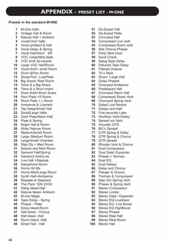
M-One hallsVintage Hall & RoomNatural Hall + Ambientvocal/Choir hallsVocal ambient & HallVocal Delay & SpringVocal Hall/Ahort SNVOC Large/Med plateVOC Amb &LiveverbLarge VOC Hall/RoomVocal Amb+ small RoomDrum &Perc RoomShare/Tom Live/PlateBig Snare/ Real RoomToms & a Big ShareToms & a Short snareDrum Amb+Short SnarePerc Plate +S RoomShort Plate + L RoomAmbience & LiveverbTap Delay/Small HallSmall/Large HallsGold Plate/Warm HallPlate & SpringBright Hall & RoomWide/ Narrow RoomMedium/Small RoomLarge /Medium RoomLarge/Small ChamberSlap Dly + Med RoomDetune and Med RoomGenericl Hall/SpringGeneric2 Amb/LiveLive Hall +SlapbakSaxophone RoomHorns Hit MeHorns Med/Large RoomSynth Hall+AmbienceRepeats & SlapbackThe Pack 1SN 2VOXDelay bleed-HallDetune bleed- AmbientM-one MagicTape Delay - SpringPhaser - PlateDelay bleed-RoomHall bleed - ChorusHall bleed -HallRoom bleed -HallSmall Hall - Hall
De-Essed HallDe-Essed PlateChorused HallCompresed Live verbCompresed Room verbWet Chorus-PhaserParty Next DoorSund CheckAalog Style DelayDetuned Tape DelayFiltered Octaver70´s StyleRoom- Large HallDelay PhasedChorused AmbiencePredelayed HallChorused Warm HallCompresed Share VerbChorused Spring VerbGated Live ReverbDelays and HallFive seconds LaterWurlitzer Verb+DelaySpread out VerbAcoustic GTRBG´s SpreadGTR Spring & DelayGTR Spring & ChorusGTR SpreadRhodes Verb & ChorusDual CompressorDual Gate/ ExpanderPhaser + TermoloDual EQDual DelaysDelay and ChorusFlanger & ChorusTremolo & CompressorSlap Dly+Spring VerbPhaser & Spring VerbStereo CompressorStereo LimiterStereo Gate / ExpanderStereo EQ-LoudnessStereo EQ -Low BoostStereo EQ HighBoostStereo PhaserStereo Real Hall Stereo Real RoomStereo Hall
51525354555657585960616263646566676869707172737475767778798081828384858687888990919293949596979899
100
123456789
1011121314151617181920212223242526272829303132333435363738394041424344454647484950
Presets in the standard M•ONE

APPENDIX - PRESET LIST M•ONE XL
43
M-One XL HallsPop VocalsSmall'n'BigConcert HallsDance VocalsFat VocalTwo Small RoomsBig Vocal LeadMedium Room/Big HallCountryRoom Big/SmalCrispy Room & DelayM-One Hall & DelayVox Plate/Warm HallWarm Club & Sn PlateWarm PlatesVocal EnsembleSmall Arena/Lrg HallDry FAT/DoubleDry Feel 1&2Dry Feel /BackgroundEmpty Room & DelayRock'n Room'n HallRock'a Billy Rev/DelWood Room Large/BigWood Room Small/MidFemale Air Big HallVox Bleed+Slap RoomBig ChoirBright Hall & DelayVocal AmbienceBig Vocal & Gtr. ChoAir/Small Guitar Rev.Super BrightAcc. Gtr. Cho&DetuneAcc. Gtr Ambi & ChoGuitar HeroGuitar Reverb Mid/LargeFor GuitarJumping-Cat GuitarSteel StringsJazzy SaxesDrums & PercDrum AmbienceLarge Snare/TomLong Snare/Tom HallSn Gate ReverbSn Plate/Ballad SnSnare FAT/HardSnare + Lead VocalSnare Natural/Crisp
Snare Tight/InYrFaceSmall Plate/Sn HallHorn Rev - Perc RevEl Piano Verb&ChorusClavinet Pha & RevWurly Trem & ChorusRoomsssssss 1/2Careless WhisperBig Viking HallAmbience & HallAmbience & RoomNonLinPingPong & HallPlay Them NoseflutesPop Dr./VocalSmall Room & DelaySmooth Plate L/XLTight or BigBrightTiles & DelayVintage Lead VocalsVintage Plate+SpringFlutter Room & DelayHold Me Now Drm/Voc80’s Hall and ChorusVocal-DynamicVocComps Hard/SoftShort Reverb Voc/SnVox Plate/Drum RoomEggbox & Dark HallComplex AmbienceConcrete BasementCloset + Locker RoomGothic CaveBathroomSmall With Open DoorEmpty Train StationWide Chorus&FlangerWindy ReverbFar Away / VolcanoXL Bright Hall/PitchXL-Plate Voc/SpringReverb & GateTweedSpring & PhaserDouble-BoomerangClassic Devils VoiceBassBoomerSFX:Phaser&TremoloSpace InvadersSpookey VoiceStone Chorus
51525354555657585960616263646566676869707172737475767778798081828384858687888990919293949596979899
100
123456789
1011121314151617181920212223242526272829303132333435363738394041424344454647484950
Presets in the M•ONE XL

APPENDIX - PRESET LIST M•ONE XL
44
M-One hallsVintage Hall & RoomNatural Hall + AmbientVocal/Choir HallsVocal ambient & HallVocal Delay & SpringVocal Hall/Ahort SNVOC Large/Med plateVOC Amb &LiveverbLarge VOC Hall/RoomVocal Amb+ small RoomDrum &Perc RoomShare/Tom Live/PlateBig Snare/ Real RoomToms & a Big ShareToms & a Short snareDrum Amb+Short SnarePerc Plate +S RoomShort Plate + L RoomAmbience & LiveverbTap Delay/Small HallSmall/Large HallsGold Plate/Warm HallPlate & SpringBright Hall & RoomWide/ Narrow RoomMedium/Small RoomLarge /Medium RoomLarge/Small ChamberSlap Dly + Med RoomDetune and Med RoomGenericl Hall/SpringGeneric2 Amb/LiveLive Hall +SlapbakSaxophone RoomHorns Hit MeHorns Med/Large RoomSynth Hall+AmbienceRepeats & SlapbackThe Pack 1SN 2VOXDelay bleed-HallDetune bleed- AmbientM-one MagicTape Delay - SpringPhaser - PlateDelay bleed-RoomHall bleed - ChorusHall bleed -HallRoom bleed -HallSmall Hall - Hall
De-Essed HallDe-Essed PlateChorused HallCompresed Live verbCompresed Room verbWet Chorus-PhaserParty Next DoorSound CheckAnalog Style DelayDetuned Tape DelayFiltered Octaver70´s StyleRoom- Large HallDelay PhasedChorused AmbiencePredelayed HallChorused Warm HallCompresed Share VerbChorused Spring VerbGated Live ReverbDelays and HallFive seconds LaterWurlitzer Verb+DelaySpread out VerbAcoustic GTRBG´s SpreadGTR Spring & DelayGTR Spring & ChorusGTR SpreadRhodes Verb & ChorusDual CompressorDual Gate/ ExpanderPhaser + TermoloDual EQDual DelaysDelay and ChorusFlanger & ChorusTremolo & CompressorSlap Dly+Spring VerbPhaser & Spring VerbStereo CompressorStereo LimiterStereo Gate / ExpanderStereo EQ-LoudnessStereo EQ-Low BoostStereo EQ-HighBoostStereo PhaserStereo Real Hall Stereo Real RoomStereo Hall
151152153154155156157158159160161162163164165166167168169170171172173174175176177178179180181182183184185186187188189190191192193194195196197198199200
101102103104105106107108109110111112113114115116117118119120121122123124125126127128129130131132133134135136137138139140141142143144145146147148149150