Momentum Equation and Its...
19
Chapter (5) Momentum Equation and Its Applications
Transcript of Momentum Equation and Its...
Chapter (5)
Momentum Equation and Its Applications
Page (97) Dr.Khalil Al-astal Eng. Ahmed Al-Agha Eng. Ruba Awad
Momentum Equation & Its Applications Fluid Mechanics
Momentum and Fluid Flow In fluid Mechanics, the analysis of motion is performed in the same way as in solid mechanics (by use of “Newton’s Laws of Motion”).
From solid mechanics (Newton’s Second Law) stated that: Total Force(F ) = ma , m = mass of the solid body , a = acceleration
But, in fluid mechanics, it is not clear what mass of moving fluid, thus we should use a different form of the equation of Newton’s Second Law.
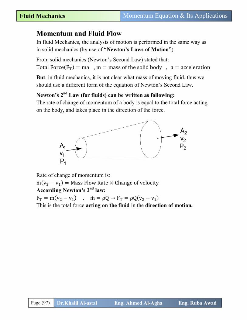
Newton’s 2nd Law (for fluids) can be written as following: The rate of change of momentum of a body is equal to the total force acting on the body, and takes place in the direction of the force.
Rate of change of momentum is: m(v − v ) = Mass Flow Rate × Change of velocity According Newton’s 2nd law: F = m(v − v ) , m = ρQ → F = ρQ(v − v ) This is the total force acting on the fluid in the direction of motion.
Page (98) Dr.Khalil Al-astal Eng. Ahmed Al-Agha Eng. Ruba Awad
Momentum Equation & Its Applications Fluid Mechanics
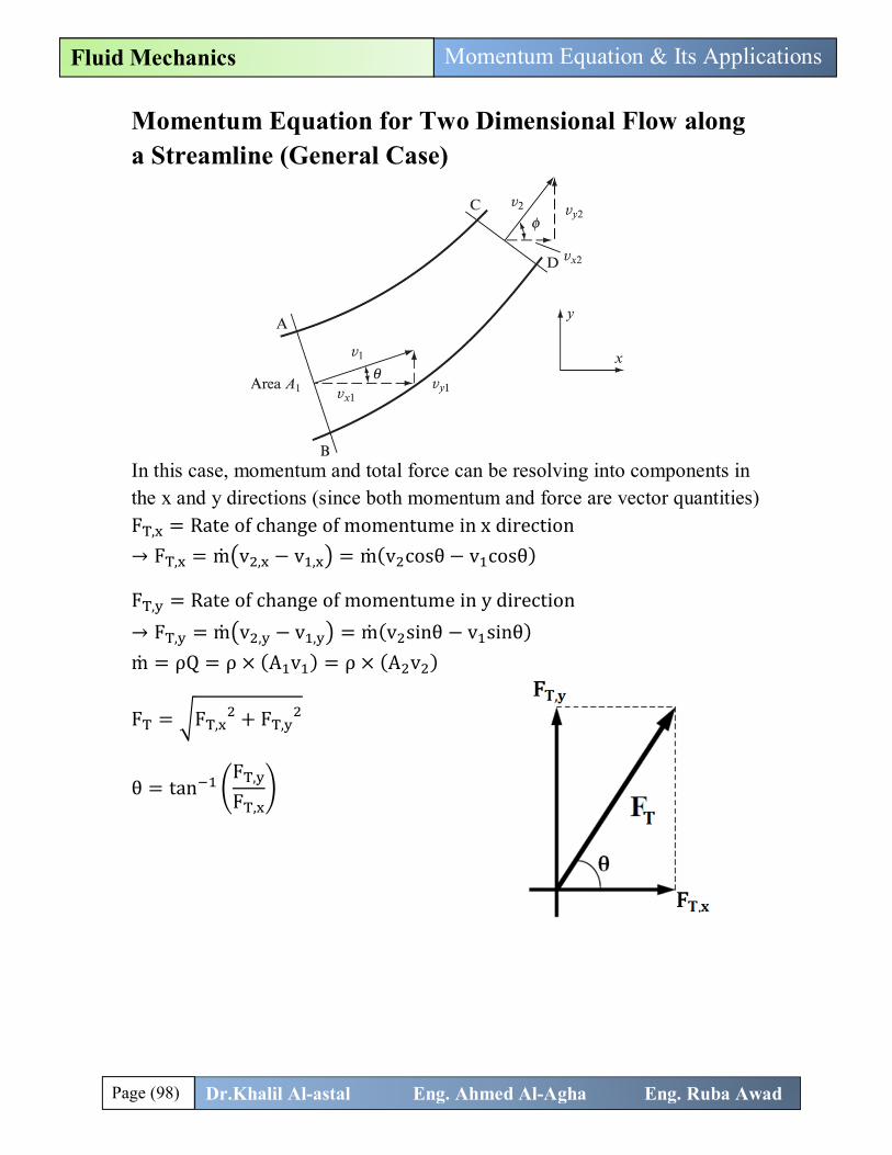
Momentum Equation for Two Dimensional Flow along a Streamline (General Case)
In this case, momentum and total force can be resolving into components in the x and y directions (since both momentum and force are vector quantities) F , = Rate of change of momentume in x direction → F , = m v , − v , = m(v cosθ − v cosθ)
F , = Rate of change of momentume in y direction → F , = m v , − v , = m(v sinθ − v sinθ) m = ρQ = ρ × (A v ) = ρ × (A v )
F = F , + F ,
θ = tanF ,
F ,
Page (99) Dr.Khalil Al-astal Eng. Ahmed Al-Agha Eng. Ruba Awad
Momentum Equation & Its Applications Fluid Mechanics
Important Note: The force 퐅퐓 is made up of three components: F = F = Force exerted in the direction of the fluid by any 퐬퐨퐥퐢퐝 퐛퐨퐝퐲 touching the control volume.
F = F = Force exerted in the direction of the fluid by a 퐛퐨퐝퐲 퐟퐨퐫퐜퐞 (gravity force). F = Fluid weight + object weight = (ρVg) + (ρVg)
F = F = Force exerted in the direction of the fluid by a 퐟퐥퐮퐢퐝 퐩퐫퐞퐬퐬퐮퐫퐞 outside the control volume F = F , + F , + ⋯ F , (If the flow is in two dimensional the pressure will be analyze in x and y directions).such that F = Pressure × Area
The final relationship for momentum equation will be as following:
퐅퐓 = 퐅퐑 + 퐅퐁+퐅퐏 = 훒퐐(퐯ퟐ − 퐯ퟏ)
F = The force exerted by the 퐛퐨퐝퐲 on the 퐟퐥퐮퐢퐝 But, R = −F = The force exerted by the 퐟퐥퐮퐢퐝 on the 퐛퐨퐝퐲 Usually the value of R is required for design purposes ∶
퐅퐓 = −퐑 + 퐅퐁+퐅퐏 = 훒퐐(퐯ퟐ − 퐯ퟏ) → 퐑 = 퐅퐁+퐅퐏 − 훒퐐(퐯ퟐ − 퐯ퟏ)
→ 퐑 = 퐅퐁+퐅퐏 + 훒퐐(퐯ퟏ − 퐯ퟐ) = Resultant force acting on the body
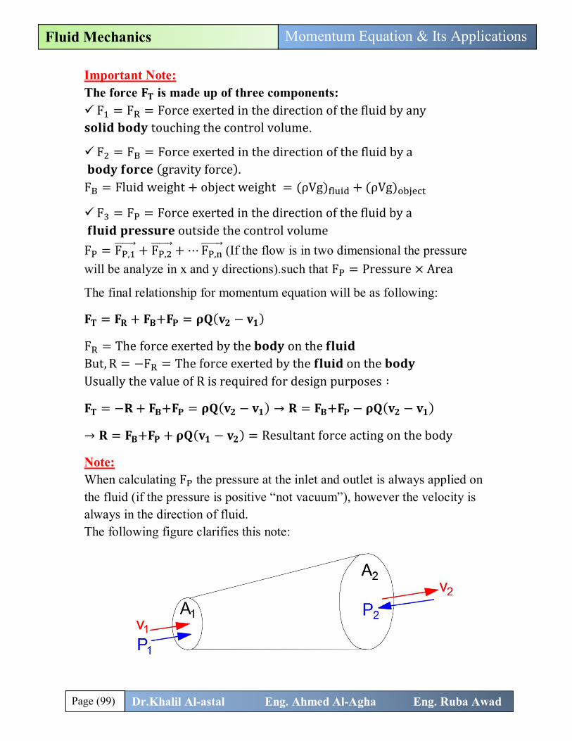
Note: When calculating F the pressure at the inlet and outlet is always applied on the fluid (if the pressure is positive “not vacuum”), however the velocity is always in the direction of fluid. The following figure clarifies this note:
Page (100) Dr.Khalil Al-astal Eng. Ahmed Al-Agha Eng. Ruba Awad
Momentum Equation & Its Applications Fluid Mechanics
Bernoulli’s Equation This equation states the relationship between velocity (v), Pressure (P), and elevation (z) for: steady flow of frictionless fluid of constant density. This equation is one of the most important equations in fluid mechanics and engineering applications (as we will discuss in Ch.6).
+ + z = constant = H (Total Head)
Bernoulli equation can be written along a streamline between two points (1) and (2) as following:
Pρg
+v2g
+ z =Pρg
+v2g
+ z + h
h = head loss between 1 and 2 (due to friction in pipes)
Assuming no losses between points 1 and 2, the equation will be: Pρg
+v2g
+ z =Pρg
+v2g
+ z
z and z are elevations of points 1 and 2 from a specific datum usually taken at point (1) → z = 0 and z = vertical distance between 1 and 2 퐚퐧퐝 퐢퐟 퐲퐨퐮 퐚퐫퐞 퐧퐨퐭 퐠퐢퐯퐞퐧 퐚퐧퐲 퐢퐧퐟퐨퐫퐦퐚퐭퐢퐨퐧 퐚퐛퐨퐮퐭 퐭퐡퐢퐬 퐝퐢퐬퐭퐚퐧퐜퐞, assume it zero (i. e. assume the two points in the same level)and caculate the pressure.
Applications of the Momentum Equation Momentum equation is used in several engineering applications as we will discuss in the problems of this chapter.
Steps in Analysis:
Draw the control volume. Decide on coordinate axis system. Calculate the total force F = ρQ(v − v ) Calculate the pressure force F (usually the pressure is known at one point and not known at the other point, so we use Bernoulli equation to find it). Calculate the body force F (if you are given the volume of the fluid). Calculate the resultant force on the system R (usually it’s required).
Page (101) Dr.Khalil Al-astal Eng. Ahmed Al-Agha Eng. Ruba Awad
Momentum Equation & Its Applications Fluid Mechanics
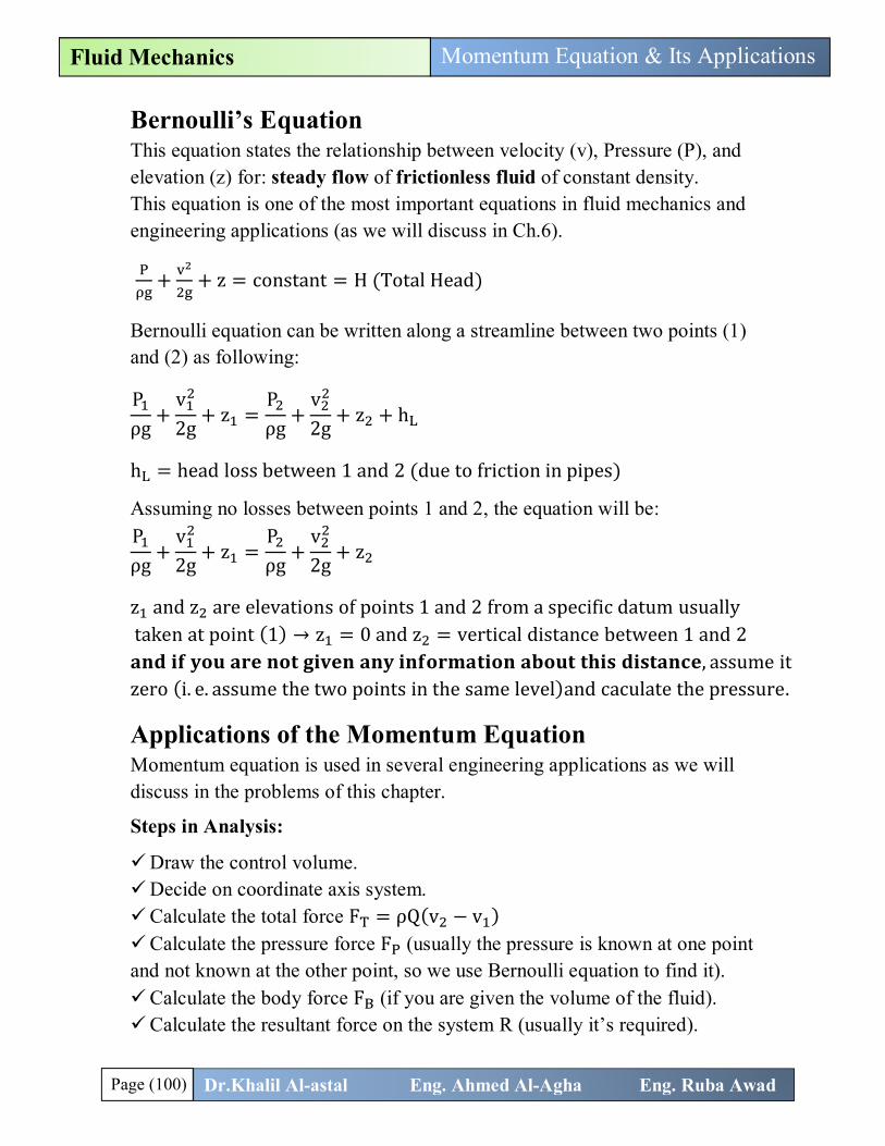
Problems 1. The figure below shows a smooth curved vane attached to a rigid foundation. The jet of water, rectangular in section, 75 mm wide and 25 mm thick, deflected on the vane with a velocity of 25m/s. Calculate the vertical and horizontal components of the force exerted on the vane and indicate in which direction these components act.
Solution R = F +F + ρQ(v − v ), but F = F = 0.0 → R = ρQ(v − v ) A = A = 0.075 × 0.025 = 0.001875 m Since A = A → v = v = 25 m/s(as given) Q = A × v = 0.001875 × 25 = 0.0468 m /s ρQ = 1000 × 0.0468 = 46.8 kg/s R = 46.8 v , − v , v , = +25 cos45 = 17.67 m/s , v , = +25 cos25 = 22.66 m/s R = 46.8(17.67 − 22.66) = −233.5 N (From right to left)✓.
R = 46.8 v , − v , v , = −25 sin45 = −17.67m/s , v , = +25 sin25 = 10.56 m/s R = 46.8(−17.67 − 10.56) = −1321.16 N (downward)✓.
Page (102) Dr.Khalil Al-astal Eng. Ahmed Al-Agha Eng. Ruba Awad
Momentum Equation & Its Applications Fluid Mechanics
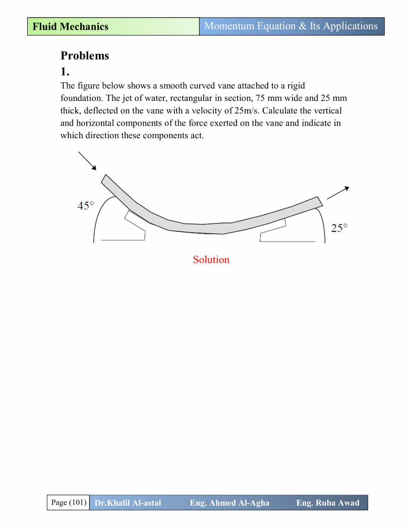
2. A square plate of mass 12.7 kg, having uniform thickness and 300 mm length of edge, is hinged so that it can swing freely about its horizontal edge. A horizontal jet, 20mm in diameter, strikes the plate with a velocity of 15 m/s. the centerline of the jet is 150mm below the upper edge of the plate so that when the plate is vertical the jet strikes the plate normally at the center. Find: (a)The force (P) must be applied at the lower edge of the plate to keep it vertical. (b) What inclination to the vertical the plate will assume under the action of the jet if allowed to swing freely.
Solution (a) Firstly we calculate the force (F) from the water to the jet: F = R = F , +F , + ρQ v , − v , F , = 0.0 and F , = 0.0 → F = R = ρQ v , − v ,
Q = Av =π4
× 0.02 × 15 = 0.0047 m /s
v , = 15 m/s (Inlet velocity)
v , = 0.0 m/s (velocity at the wall is zero)
→ F = R = 1000 × 0.0047(15 − 0) = 70.5 N
A B
Page (103) Dr.Khalil Al-astal Eng. Ahmed Al-Agha Eng. Ruba Awad
Momentum Equation & Its Applications Fluid Mechanics
Now by taking summation of moments about hinge equal zero:
M@ = 0.0 → 70.5 × 0.15 = P × 0.3 → P = 35.25 N ✓.
(b) Firstly we calculate the force (F) from the water to the jet: Assume x-direction is in the same direction of the force F. F = R = F , +F , + ρQ v , − v , F , = 0.0 and F , = 0.0 → F = R = ρQ v , − v ,
Q = Av =π4
× 0.02 × 15 = 0.0047 m /s
v , = 15 cosθ (Inlet velocity)
v , = 0.0 m/s (velocity at the wall is zero)
→ F = R = 1000 × 0.0047(15 cosθ − 0) = 70.5 cosθ N
The weight of the Plate is act at center G and is equal: W = mg = 12.7 × 9.81 = 124.58 N Now by taking summation of moments about hinge equal zero:
M@ = 0.0 → 70.5 cosθ ×0.15cosθ
= 124.58 × 0.15 sinθ
→ θ = 34.46°✓.
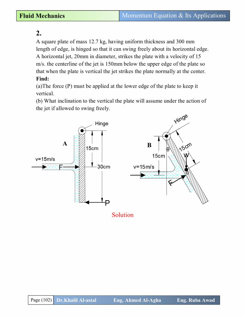
3. A jet of water strikes a stationary curved vane and deflected 150° from its original direction. The discharge from the jet is 0.68 kg/s and the jet velocity is 24 m/s. Assume that the velocity remains unchanged between inlet and outlet. Determine the magnitude and direction of reaction on vane in the following two cases: (1) if the van is stationary, (2) if the van moves with velocity of 8m/s.
30°

Page (104) Dr.Khalil Al-astal Eng. Ahmed Al-Agha Eng. Ruba Awad
Momentum Equation & Its Applications Fluid Mechanics
Solution (1) If the vane is stationary (U=0.0)
R = F +F + ρQ(v − v ), but F = F = 0.0 → R = ρQ(v − v ) ρQ = m = 0.68 kg/s (as given) R = 0.68 v , − v , v , = 24 m/s , v , = −24 cos30 = −20.78 m/s R = 0.68(24 − (−20.78)) = 30.45 N
R = 0.68 v , − v , v , = 0.0 , v , = −24 sin30 = −12 m/s R = 0.68(0 − (−12)) = 8.16 N
R = R + R = 30.45 + 8.16 = 31.52 N✓.
θ = tanRR
= tan8.16
30.45= 15°✓.
(2) If the vane moves with velocity (U= 8 m/s):
Always we deal with relative velocity between water in get and vane In this case m = 휌푄 = ρ(v − u) × A → m = 1000 × A × (24 − 8) → m = 16000A How we can calculate A: In the first case (u = 0.0) → m = 0.68 = 1000 × 24 × A → A = 2.83 × 10 → m@ = 16000 × 2.83 × 10−5 = 0.453 kg/s
R = 0.453 v , − v , v , = 24 − 8 = 16푚/푠 v , = −24 cos30 − 8 = −28.78 m/s R = 0.453(16 − (−28.78)) = 20.28 N
R = 0.453 v , − v , v , = 0.0 , v , = −24 sin30 − 0 = −12 m/s R = 0.453(0 − (−12)) = 5.436N
R = R + R = 20.28 + 5.136 = 21N✓.
θ = tanRR
= tan5.13620.28
= 14.21°✓.
Page (105) Dr.Khalil Al-astal Eng. Ahmed Al-Agha Eng. Ruba Awad
Momentum Equation & Its Applications Fluid Mechanics
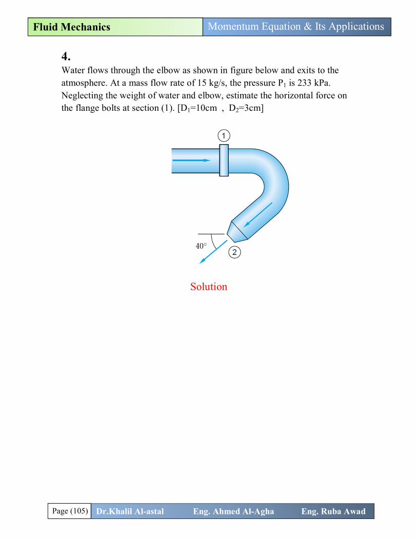
4. Water flows through the elbow as shown in figure below and exits to the atmosphere. At a mass flow rate of 15 kg/s, the pressure P1 is 233 kPa. Neglecting the weight of water and elbow, estimate the horizontal force on the flange bolts at section (1). [D1=10cm , D2=3cm]
Solution The horizontal force on flange bolts equals the horizontal component of the fluid force (Rx). R = F , +F , + ρQ v , − v , but F = 0.0 (neglect the wieght of water and elbow "as given") → R = F , + ρQ v , − v , 퐂퐚퐜퐮퐥퐚퐭퐢퐨퐧 퐨퐟 퐅퐓,퐱 = 훒퐐 퐯ퟏ,퐱 − 퐯ퟐ,퐱 ρQ = 15 kg/s (as given) → 1000Q = 15 → Q = 0.015 m /s
v =QA
=0.015
π4 × 0.1
= 1.9 m/s , v =Q
A=
0.015π4 × 0.03
= 21.22 m/s
v , = +1.9 m/s , v , = −21.22 cos40 = −16.25 m/s
→ F , = 15(1.9 − (−21.22)) = 346.8 N
Page (106) Dr.Khalil Al-astal Eng. Ahmed Al-Agha Eng. Ruba Awad
Momentum Equation & Its Applications Fluid Mechanics
퐂퐚퐥퐜퐮퐥퐚퐭퐢퐨퐧 퐨퐟 퐅퐏,퐱: The pressure at section (1) is 233 kPa and the pressure at section (2) is 0.0 because water in section (2) exposed to atmosphere.
→ F , = P A + 0.0 = 233 × 10 ×π4
× 0.1 = 1830 N
→ F = R = 1830 + 346.8 = 2176.8 N✓.
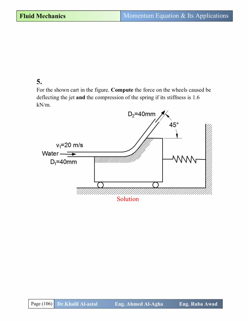
5. For the shown cart in the figure. Compute the force on the wheels caused be deflecting the jet and the compression of the spring if its stiffness is 1.6 kN/m.
Solution R = F +F + ρQ(v − v ), but F = F = 0.0 → R = ρQ(v − v ) → force from wter to the jet R = ρQ v , − v ,
F = 0.0 → R + F = 0.0 → F = −R = ρQ v , − v ,
Q = A × v =π4
× 0.04 × 20 = 0.025 m /s
Since A = A → v = v = 20 m/s v , = 0.0 v , = +20 sin45 = 14.14 m/s → F = 1000 × 0.025(14.14 − 0) = 353.55 N✓.

Page (107) Dr.Khalil Al-astal Eng. Ahmed Al-Agha Eng. Ruba Awad
Momentum Equation & Its Applications Fluid Mechanics
R = ρQ v , − v ,
F = 0.0 → R + F = 0.0 → F = −R = ρQ v , − v ,
Q = 0.025 m /s v , = 20 m/s v , = +20 cos45 = 14.14 m/s → F = 1000 × 0.025(14.14 − 20) = −146.5 N F = −K X (Compression) → F = −146.5 = −1.6 × 1000 X → X = 0.0915m = 91.5 mm✓.
6. The 6-cm-diameter water jet shown in figure below strikes a plate containing a hole of 4-cm diameter. Part of the jet passes through the hole, and part is deflected. Determine the horizontal force required to hold the plate.
Solution The most important note in this question is the flow is not the same at 1 and 2 because the flow at 1 divided into three parts (up, down and to the hole).
The force on the plate equals the horizontal component of the force of water on the plate (Rx).
R = F , +F , + ρQ v , − v , F , = 0.0 (No body force in x direction)
Page (108) Dr.Khalil Al-astal Eng. Ahmed Al-Agha Eng. Ruba Awad
Momentum Equation & Its Applications Fluid Mechanics
F , = 0.0 (No given presures)
→ R = ρQ v , − v , But‼ (Whats wrong ) since Q is not the same at 1 and 2 →→ F = R = ρQ v , − ρQ v ,
Q = v A = 25 ×π4
× 0.06 = 0.0706 m /s
Q = v A = 25 ×π4
× 0.04 = 0.0314 m /s
→ F = 1000 × 0.0706 × 25 − 1000 × 0.0314 × 25 = 980 N✓.
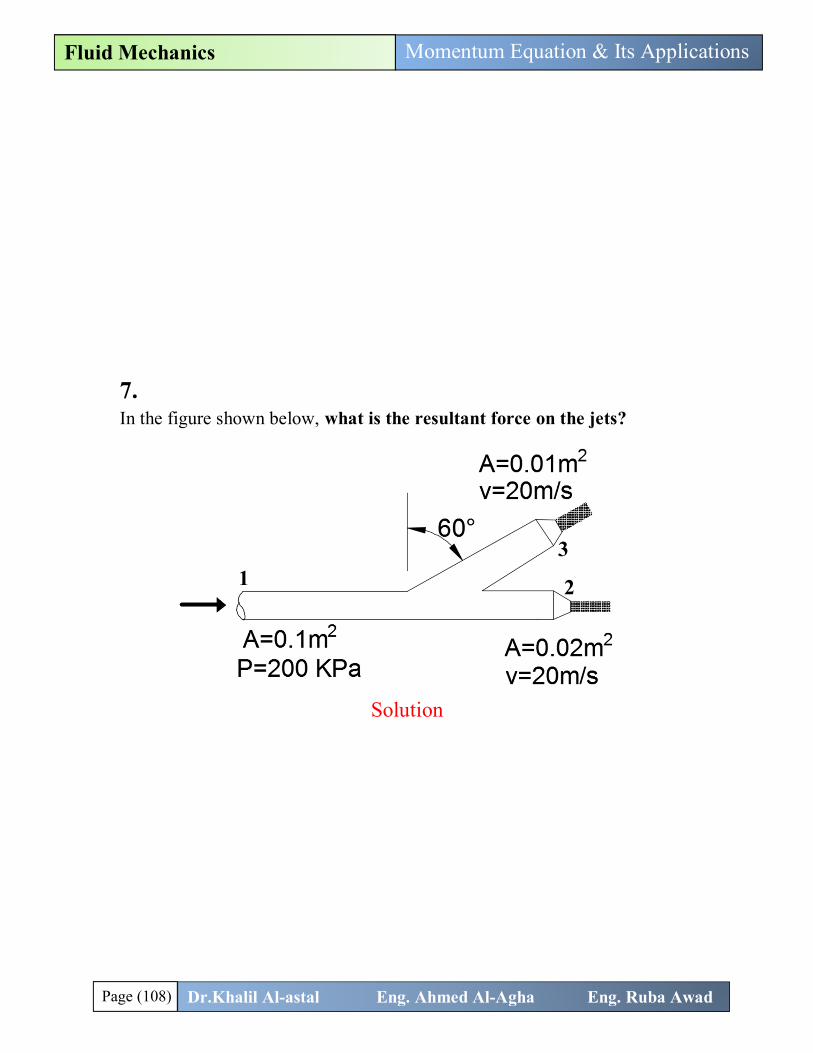
7. In the figure shown below, what is the resultant force on the jets?
Solution Here the fluid also divided into two components. R = F , +F , + ρQ v , − v , R = F , +F , + ρQ v , − v , No body force is given→ F , = F , = 0.0
R = F , + ρQ v , − v , R = F , + ρQ v , − v , But, because the value of Q is not constant→→
1 3
2

Page (109) Dr.Khalil Al-astal Eng. Ahmed Al-Agha Eng. Ruba Awad
Momentum Equation & Its Applications Fluid Mechanics
R = F , + ρQ v , − ρQ v , − ρQ v , (1 is inlet, 2 and 3 are outlets) R = F , + ρQ v , − ρQ v , − ρQ v ,
Q = A v = 0.02 × 20 = 0.4 m /s Q = A v = 0.01 × 20 = 0.2 m /s → Q = Q + Q = 0.2 + 0.4 = 0.6m /s
→ v =QA
=0.60.1
= 6 m/s
퐂퐚퐥퐜퐮퐥퐚퐭퐢퐨퐧 퐨퐟 퐑퐱: F , =? ? The pressure at 1 is 200 kPa (in x direction), however the pressure at 2 and 3 is 0.0 because they exposed to atmosphere. F , = 200 × 10 + 0 + 0 = 200000 Pa v , = +6 m/s , v , = +20 m/s , v , = +20 cos30 = +17.32 m/s
→ R = 200000 + 1000 × 0.6 × 6 − 1000 × 0.4 × 20 − 1000 × 0.2 × 20
→ R = 191600 N
퐂퐚퐥퐜퐮퐥퐚퐭퐢퐨퐧 퐨퐟 퐑퐲: F , =? ? The pressure at 1 is 0.0 (in y direction), also the pressure at 2 and 3 is 0.0 because they exposed to atmosphere. F , = 0 + 0 + 0 = 0 v , = 0 , v , = 0 , v , = +20 sin30 = 10 m/s
→ R = 0.0 + 1000 × 0.6 × 0 − 1000 × 0.4 × 0 − 1000 × 0.2 × 10
→ R = −2000 N
= R + R = 191600 + −2000 = 191610.4 N✓.
θ = tanRR
= tan−2000191600
= −0.6°✓.
Page (110) Dr.Khalil Al-astal Eng. Ahmed Al-Agha Eng. Ruba Awad
Momentum Equation & Its Applications Fluid Mechanics
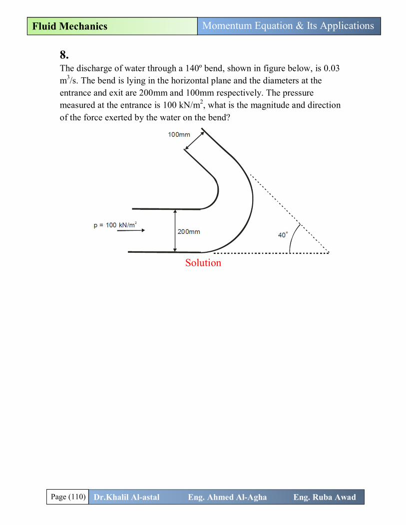
8. The discharge of water through a 140º bend, shown in figure below, is 0.03 m3/s. The bend is lying in the horizontal plane and the diameters at the entrance and exit are 200mm and 100mm respectively. The pressure measured at the entrance is 100 kN/m2, what is the magnitude and direction of the force exerted by the water on the bend?
Solution R = F +F + ρQ(v − v ) R = F , +F , + ρQ v , − v , R = F , +F , + ρQ v , − v ,
퐂퐚퐜퐮퐥퐚퐭퐢퐨퐧 퐨퐟 퐅퐓 = 훒퐐(퐯ퟏ − 퐯ퟐ)
Q = 0.03 m /s → v =QA
=0.03
π4 × 0.2
= 0.955 m/s
v =Q
A=
0.03π4 × 0.1
= 3.82 m/s
F , = ρQ v , − v , ρQ = 1000 × 0.03 = 30 kg/s v , = v = +0.955 m/s , v , = −v cos40 = −3.82 cos40 = −2.92 m/s
F , = 30(0.955 − (−2.92)) = 116.25 N

Page (111) Dr.Khalil Al-astal Eng. Ahmed Al-Agha Eng. Ruba Awad
Momentum Equation & Its Applications Fluid Mechanics
F , = ρQ v , − v , ρQ = 30 kg/s v , = 0.0 , v , = +v sin40 = 3.82 sin40 = 2.45 m/s
F , = 30(0 − 2.45) = −73.5 N
Calculation of Body force (퐅퐁): The volume of the fluid in the pipe is not given, so we can neglect the body force.
Calculation of Pressure force (퐅퐏): F = F , + F , P = 100 kPa = 10000 Pa , P =? ? we use bernoulli equation to find P Pρg
+v2g
+ z =Pρg
+v2g
+ z (Assume no losses)
Since the bend is in the horizontal plane , so the elevation of the two points is the same (i.e. canceled each other from Bernoulli equation). Pρg
+v2g
=Pρg
+v2g
→→100000
1000 × 9.81+
0.9552 × 9.81
=P
1000 × 9.81+
3.822 × 9.81
→ P = 93160 Pa
F , = Pressure force applied on the x direction
F , = 100000 ×π4
× 0.2 + 93160 cos 40 ×π4
× 0.1 = 3702.1 N
F , = Pressure force applied on the y direction
F , = 0.0 − 93160 sin 40 ×π4
× 0.1 = −470.3 N
Now, R = F , +F , + ρQ v , − v , = 0 + 3702.1 + 116.25 = 3818.35 N R = F , +F , + ρQ v , − v , = 0 + (−470.3) + (−73.5) = −543.8 N
R = R + R = 3818.35 + −543.8 = 3856.9 N✓.
θ = tanRR
= tan−543.83818.35
= −8.1°✓.
Page (112) Dr.Khalil Al-astal Eng. Ahmed Al-Agha Eng. Ruba Awad
Momentum Equation & Its Applications Fluid Mechanics
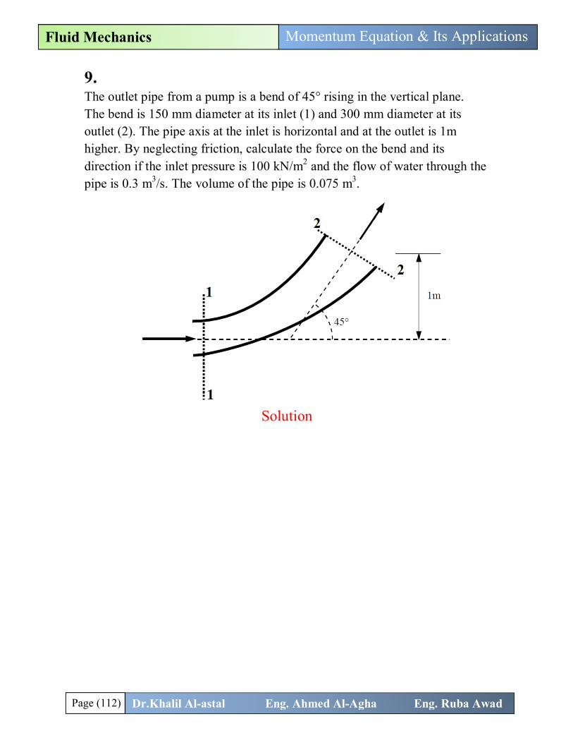
9. The outlet pipe from a pump is a bend of 45° rising in the vertical plane. The bend is 150 mm diameter at its inlet (1) and 300 mm diameter at its outlet (2). The pipe axis at the inlet is horizontal and at the outlet is 1m higher. By neglecting friction, calculate the force on the bend and its direction if the inlet pressure is 100 kN/m2 and the flow of water through the pipe is 0.3 m3/s. The volume of the pipe is 0.075 m3.
Solution R = F , +F , + ρQ v , − v , R = F , +F , + ρQ v , − v ,
퐂퐚퐜퐮퐥퐚퐭퐢퐨퐧 퐨퐟 퐅퐓 = 훒퐐(퐯ퟏ − 퐯ퟐ)
Q = 0.3 m /s → v =QA
=0.3
π4 × 0.15
= 16.97 m/s
v =Q
A=
0.3π4 × 0.3
= 4.24 m/s
F , = ρQ v , − v , ρQ = 1000 × 0.3 = 300 kg/s v , = v = +16.97 m/s , v , = +v cos45 = 4.24 cos45 = 3 m/s
F , = 300(16.97 − 3) = 4191 N

Page (113) Dr.Khalil Al-astal Eng. Ahmed Al-Agha Eng. Ruba Awad
Momentum Equation & Its Applications Fluid Mechanics
F , = ρQ v , − v , ρQ = 300 kg/s v , = 0.0 , v , = +v sin45 = 4.24 sin45 = 3 m/s
F , = 300(0 − 3) = −900 N
Calculation of Body force (퐅퐁): The volume of the fluid in the pipe equals 0.075 m3 F , = 0.0 (no weight in x direction) F , = −ρVg = −1000 × 0.075 × 9.81 = −735.75 N
Calculation of Pressure force (퐅퐏): F = F , + F , P = 100 kPa = 10000 Pa , P =? ? we use bernoulli equation to find P Pρg
+v2g
+ z =Pρg
+v2g
+ z (Assume no losses)
Assume the datum is at the centerline of the inlet: Pρg
+v2g
+ z =Pρg
+v2g
+ z
→→100000
1000 × 9.81+
16.972 × 9.81
+ 0 =P
1000 × 9.81+
4.242 × 9.81
+ 1
→ P = 225191.65 Pa
F , = Pressure force applied on the x direction
F , = 100000 ×π4
× 0.15 − 225191.65 cos 45 ×π4
× 0.3 = −9488.5 N
F , = Pressure force applied on the y direction
F , = 0.0 − 225191.65 cos 45 ×π4
× 0.32 = −11255.65 N
Now, R = F , +F , + ρQ v , − v , = 0 + −9488.5 + 4191 = −5297.5 N R = F , +F , + ρQ v , − v , → R = −735.75 + (−11255.65) + (−900) = −12891.4 N

Page (114) Dr.Khalil Al-astal Eng. Ahmed Al-Agha Eng. Ruba Awad
Momentum Equation & Its Applications Fluid Mechanics
R = R + R = −5297.5 + −12891.4 = 13937.4 N✓.
θ = tanRR
= tan−12891.4−5297.5
= 67.66°✓.