MOMENTUM 3400 CE/3800 RC OWNER S MANUAL
86
MOMENTUM 3400 CE/3800 RC OWNER ’S MANUAL C40 OWNER’S MANUAL
Transcript of MOMENTUM 3400 CE/3800 RC OWNER S MANUAL
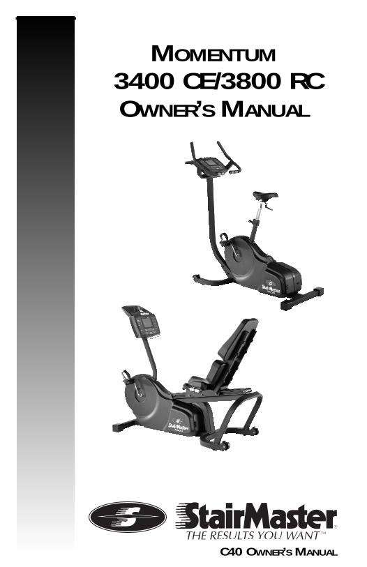
MOMENTUM
3400 CE/3800 RC OWNER’S MANUAL
C40 OWNER’S MANUAL

Page iii
© 2001 StairMaster Health & Fitness Products, Inc. StairMaster is a registeredtrademark of StairMaster Health & Fitness Products, Inc. in the
United States and other countries. StairMaster is a Rutledge Capital company.
P/N 25559-A
Printed in the United States. © 2001 StairMaster Health & Fitness Products, Inc.
All rights reserved.
Corporate Headquarters12421 Willows Road N.E., Suite 100
Kirkland, WA 98034
(800) 635-2936(425) 823-1825
Fax (425) 823-9490www.stairmaster.com
Page iv
WARRANTYThis is to certify that the StairMaster® Momentum systems cycle ergometer iswarranted for a period of three years by StairMaster Health & Fitness Products,Inc. to be free of all defects in materials and workmanship. This warranty doesnot apply to any defect caused by negligence, misuse, accident, alteration,improper maintenance, or an “act of God.” This warranty is nontransferable fromthe original owner.
If, within three years from the date of purchase, any part of theStairMaster Momentum systems cycle ergometer should fail to operate properly(except any accessories or the battery), contact our Customer ServiceDepartment to report the problem. International customers should contact theirlocal distributor. When calling, please be prepared to provide our customerservice representative with the following information:
• Your name, shipping address, and telephone number;• The model number of the inoperable unit;• The serial number of the inoperable unit (located on the frame);• The date(s) of purchase for the inoperable unit(s);• Your billing address.
This information will ensure that you are the only one ordering parts underyour warranty protection. If warranty replacement parts are shipped to you, youmay be required to return the inoperable part. To facilitate this process, thefollowing policy has been established:
• Please call our Customer Service Department to receive a ReturnMaterials Authorization (RMA) prior to shipment.
• StairMaster Health & Fitness Products, Inc. will incur all freight (i.e.,shipping and handling) charges for warranty parts ordered for a productthat is less than 45 days old. The parts will be shipped to you via anovernight courier.
• The customer is responsible for freight charges on warranty parts forproducts that are more than 45 days old. Customers will not beresponsible for the return shipment of the inoperable parts (see below).
• Some inoperable warranty parts must be promptly returned to ourCustomer Service Department. We will pay the shipping cost for theinoperable warranty parts. Detailed instructions are included with eachwarranty replacement part shipment.
StairMaster Health & Fitness Products, Inc. neither makes, assumes, norauthorizes any representative or other person to make or assume for us, anyother warranties whatsoever, whether expressed or implied, in connection withthe sale, service, or shipment of our products. We reserve the right to makechanges and improvements in our products without incurring any obligation tosimilarly alter products previously purchased. In order to maintain your productwarranty and to ensure the safe and efficient operation of your StairMasterMomentum systems cycle ergometer, only authorized replacement parts can beused. This warranty is void if any parts other than those provided by StairMasterHealth & Fitness Products, Inc. are used.
* Note: Aerosol products cannot be transported via air.

Page v
PREFACE
The StairMaster® Momentum systems cycle ergometer is a safe and effectiveway to develop aerobic fitness while conditioning the major muscles of the lowerbody. In order to get the best results, and to keep your machine in peak operatingcondition, you should carefully read and follow the guidelines presented in thismanual.
WHAT IS IN THIS MANUAL?
This manual includes sections on safety, installation, operating instructions,preventive maintenance, and detailed information on troubleshooting and repairprocedures. An appendix at the end of the manual provides important phonenumbers and drawings.
WHAT IS THE STAIRMASTER STRATUS CYCLEERGOMETER?
The Momentum systems cycle ergometers have 20 levels of intensity for eachexercise program. The Momentum uses a variable resistance system to maintainconstant power within any given intensity level. The resistance decreases as youpedal faster and increases as you pedal slower. The variable resistance systemensures you will do the same amount of work regardless of how fast or slow youpedal.
WHAT IS THE BATTERY CHARGER USED FOR?
Plug in the battery charger only to recharge a weak battery. Exercising on theMomentum cycle while the battery charger is connected will not damage themachine, but will affect the power output (watts) statistics.
Page vi
CONTENTS
SAFETY GUIDELINES ....................................................................................... 1
INTRODUCTION ................................................................................................ 3
INSTALLATION INSTRUCTIONS..................................................................... 5
BASIC OPERATING INSTRUCTIONS ............................................................. 6Adjustments .......................................................................................... 6Seat Height Adjustment on the Momentum 3400 CE .......................... 6Seat Adjustment on the Momentum 3800 RC ...................................... 6Foot Strap Adjustment on the Momentum 3400 CE ............................. 7Basic Instructions For First-Time Users ................................................ 8Begin Exercising .................................................................................... 8Rest Periods .......................................................................................... 9Cool down ............................................................................................. 9
GENERAL EXERCISE GUIDELINES ................................................................. 10Setting a Goal ....................................................................................... 10Flexibility Training ................................................................................. 10Exercise Principles ................................................................................ 11
HEART RATE MONITORING ............................................................................ 12Heart Rate Input .................................................................................... 12Locked/Non-locked Option ................................................................... 12Error Messages ..................................................................................... 13
TELEMETRY HEART RATE ................................................................................ 14Using The Transmitter Belt ................................................................... 14Maintaining The Transmitter Belt ......................................................... 15
CONTACT HEART RATE.................................................................................... 16Contact Heart Rate ............................................................................... 16Using The Contact Heart Rate .............................................................. 16
MOMENTUM SYSTEMS CONSOLE ............................................................... 17Display Window .................................................................................... 17Numeric Keypad .................................................................................... 17Entertainment Keypad .......................................................................... 17
Page vii
CONTENTS
Intensity Level Keys .............................................................................. 17Stop Key ................................................................................................ 17Workout Statistics ................................................................................ 19Exercise Program Keypad ..................................................................... 20
The Quick Start Program................................................................ 20The Manual Program ..................................................................... 20The Fat Burner Program ................................................................. 21The Aerobic Training Program ....................................................... 21The Speed Intervals Program ........................................................ 21The Constant Heart Rate Program................................................. 22
The Fitness Test Programs .................................................................... 23Understanding Submaximal Exercise Testing ............................... 23Pretest Screening .......................................................................... 25The StairMaster® Submaximal Fit Test ......................................... 25Turning on the StairMaster Fitness Test ........................................ 28
Console Codes ...................................................................................... 29Custom Codes ................................................................................ 29Machine Status Codes .................................................................. 31Diagnostic Codes ........................................................................... 31Configuration Codes ...................................................................... 33Fitness Testing Codes .................................................................... 33
MAINTENANCE INSTRUCTIONS ................................................................... 34Helpful Hints ......................................................................................... 34Tool List ................................................................................................. 34Maintenance Records ........................................................................... 34
Resetting The Maintenance Timer ................................................ 35Preventive Maintenance ....................................................................... 35
Cleaning ......................................................................................... 35Weekly Inspection ......................................................................... 36Monthly Inspection ........................................................................ 36
TROUBLESHOOTING GUIDELINES ................................................................ 39General Troubleshooting Guidelines ..................................................... 39Systematic Electrical Troubleshooting .................................................. 39Systematic Mechanical Troubleshooting.............................................. 42Console Diagnostic Tests ...................................................................... 43
Diagnostic Codes ........................................................................... 43
Page viii
CONTENTS
Display Test ................................................................................... 43Keypad Test ................................................................................... 43Serial Port Test .............................................................................. 44Alternator Test ............................................................................... 44Tach Test ........................................................................................ 45Error Reporting ............................................................................... 45Contact Heart Rate ........................................................................ 46Telemetry (Polar®) Heart Rate Test ................................................ 47
PARTS REMOVAL AND REPLACEMENT ....................................................... 48Alternator .............................................................................................. 48Covers ................................................................................................... 49Console ................................................................................................. 50Handlebar Assembly (3400 CE) ............................................................. 50Seat (3300 CE) ....................................................................................... 51Seat (3800 RC) ...................................................................................... 52Seat Post (3400 CE) ............................................................................... 53Seat Handle (3400 CE) .......................................................................... 54Seat Track (3800 RC .............................................................................. 54High Torque Drive (HTD) Belt ................................................................ 55Poly-V Belt ............................................................................................. 55Intermediate Poly-V Pulley Assembly ................................................... 56Pedals .................................................................................................... 57Crank and Bottom Bracket Assembly ................................................... 58
GROUNDING INSTRUCTIONS ........................................................................ 60
NOTICE OF FCC COMPLIANCE ....................................................................... 61
APPENDICESImportant Phone Numbers .................................................................... 62Battery Recycling Centers ..................................................................... 63Figures 8 - 21 ........................................................................................ 65
LIST OF TABLES
Table 1: Dimensions of the Momentum Cycle Ergometer .................... 4Table 2: Fitness Rating Norms(VO2max) ............................................... 28Table 3: Preventive Maintenance Schedule ......................................... 38
Page ix
LIST OF ILLUSTRATIONS
Figure 1: Major Parts, 3400 CE ............................................................. 3Figure 2: Major Parts, 3800 RC ............................................................. 4Figure 3: Leg Levelers ........................................................................... 5Figure 4: Transmitter Belt ...................................................................... 15Figure 5: Momentum Systems Console ................................................ 17Figure 6: StairMaster® Fitness Protocol ............................................... 27Figure 7: Grounding System .................................................................. 60Figure 8: Cover Fasteners ..................................................................... 65Figure 9: Cover Fastener Location, 3400 CE ......................................... 66Figure 10: Cover Fastener Location, 3800 RC ....................................... 67Figure 11: Right Side View, 3400 CE ..................................................... 68Figure 12: Right Side View, 3800 RC .................................................... 69Figure 13: Seat Post Assembly, 3400 CE .............................................. 70Figure 14: Seat Assembly, 3800 RC ...................................................... 71Figure 15: Seat Track Assembly, 3800 RC ............................................. 72Figure 16: Intermediate Poly-V Assembly ............................................. 73Figure 17: Crank Assembly ................................................................... 74Figure 18: Alternator/Flywheel Assembly ............................................ 75Figure 19: Wire Connections ................................................................ 76Figure 20: Power Control Board Plug-ins .............................................. 77Figure 21: Wiring Diagram .................................................................... 78
CONTENTS
Page 1
WHEN USING ELECTRICAL EQUIPMENT, ALWAYS FOLLOW THESE BASIC PRECAUTIONS:
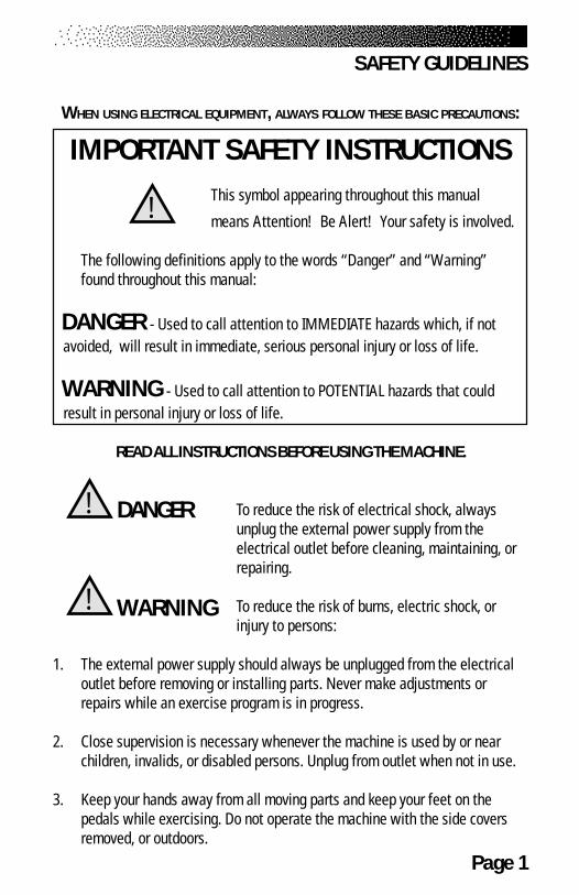
IMPORTANT SAFETY INSTRUCTIONSThis symbol appearing throughout this manual
means Attention! Be Alert! Your safety is involved.
The following definitions apply to the words “Danger” and “Warning”found throughout this manual:
DANGER - Used to call attention to IMMEDIATE hazards which, if not avoided, will result in immediate, serious personal injury or loss of life.
WARNING - Used to call attention to POTENTIAL hazards that could result in personal injury or loss of life.
READ ALL INSTRUCTIONS BEFORE USING THE MACHINE.
To reduce the risk of electrical shock, alwaysunplug the external power supply from theelectrical outlet before cleaning, maintaining, orrepairing.
To reduce the risk of burns, electric shock, orinjury to persons:
1. The external power supply should always be unplugged from the electricaloutlet before removing or installing parts. Never make adjustments orrepairs while an exercise program is in progress.
2. Close supervision is necessary whenever the machine is used by or nearchildren, invalids, or disabled persons. Unplug from outlet when not in use.
3. Keep your hands away from all moving parts and keep your feet on thepedals while exercising. Do not operate the machine with the side coversremoved, or outdoors.
!
SAFETY GUIDELINES
DANGER!
WARNING!

Page 2
4. Use this machine only for its intended use as described in this Manual. Donot use parts, attachments, or accessories other than those provided byStairMaster® Health & Fitness Products.
5. Do not use the external power supply if it has a damaged cord or plug, if itis not working properly, if it has been dropped or damaged, or droppedinto water. Contact our Customer Service Department to arrange for thereturn of damaged parts.
6. Connect the external power supply to a properly grounded AC wall outlet;refer to the “Grounding Instructions” section. Keep all cords away fromheated surfaces.
7. To disconnect the external power supply, remove the plug from the ACwall outlet.
8. Never drop or insert any object into any opening on the machine.
9. Do not operate where aerosol (spray) products are being used.
10. Always wear insulated gloves when handling batteries.
11. Do not crush, incinerate, or dismantle the battery. The electrolytecontains sulfuric acid which can cause serious damage to eyesand skin. Should this occur, flush profusely with water and seekmedical attention.
12. Do not use the machine outdoors.
The safety level given by the design of this equipment can only be maintainedwhen the equipment is regularly examined for damage and wear. Inoperablecomponents shall be replaced immediately or the equipment shall be put out ofuse until it is repaired. Failure to follow all guidelines may compromise theeffectiveness of the exercise experience, expose yourself (and possibly others) toinjury, and reduce the longevity of the machine. Follow all training instructionslisted in the manual and/or on the machine. Physical injury may result fromincorrect or excessive training.
SAVE THESE INSTRUCTIONS
SAFETY GUIDELINES

Page 3
Before leaving the StairMaster manufacturing facility in Tulsa, Oklahoma, yourStairMaster® Momentum cycle ergometer was thoroughly inspected and testedto ensure proper operation. The major parts of the StairMaster Momentum 3400CE and 3800 RC are shown in Figures 1 and 2.
Figure 1: Major Parts, 3400 CE
INTRODUCTION
Seat adjustment knobSeat
Console
Pedal footstrap
Leg leveler
Transport wheel
Page 4
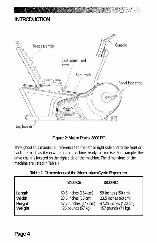
INTRODUCTION
Figure 2: Major Parts, 3800 RC
Throughout this manual, all references to the left or right side and to the front orback are made as if you were on the machine, ready to exercise. For example, thedrive chain is located on the right side of the machine. The dimensions of themachine are listed in Table 1.
Table 1. Dimensions of the Momentum Cycle Ergometer
3400 CE 3800 RC
Length 60.5 inches (154 cm) 59 inches (150 cm) Width 23.5 inches (60 cm) 23.5 inches (60 cm) Height 57.75 inches (147 cm) 47.25 inches (120 cm) Weight 125 pounds (57 kg) 157 pounds (71 kg)
Page 5
Assemble your machine before use. Machines shipped outside the United Statesneed to be uncrated before they can be assembled; refer to the “UncratingInstructions” included with your machine for the details.
1. Remove all shipping material and the battery charger from themachine. The battery charger is only used to recharge a lowbattery.
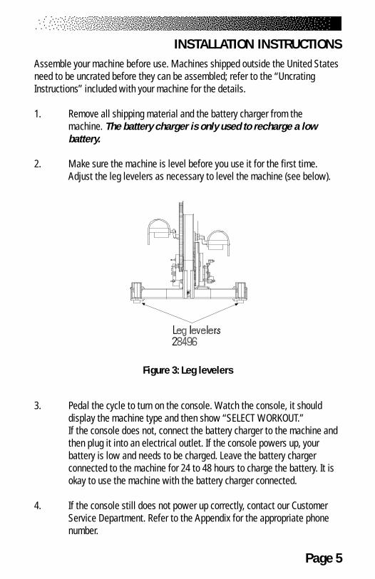
2. Make sure the machine is level before you use it for the first time.Adjust the leg levelers as necessary to level the machine (see below).
Figure 3: Leg levelers
3. Pedal the cycle to turn on the console. Watch the console, it shoulddisplay the machine type and then show “SELECT WORKOUT.”If the console does not, connect the battery charger to the machine andthen plug it into an electrical outlet. If the console powers up, yourbattery is low and needs to be charged. Leave the battery chargerconnected to the machine for 24 to 48 hours to charge the battery. It isokay to use the machine with the battery charger connected.
4. If the console still does not power up correctly, contact our CustomerService Department. Refer to the Appendix for the appropriate phonenumber.
INSTALLATION INSTRUCTIONS

Page 6
ADJUSTMENTS
You should check two adjustments before using your StairMaster® Momentumsystems cycle ergometer: the seat and the pedal foot strap length.
Seat Height Adjustment on the Momentum 3400 CE
Sit on the seat. Put both feet onto the pedals and into the foot straps. Pedalslowly and then stop when one leg is extended and your foot is as close to thefloor as possible. The knee of the extended leg should be slightly bent when thesole of your foot is parallel to the floor. If you need to adjust the seat height, getoff the bike and stand to one side. The seat adjustment knob is located on theframe tube just below the front part of the seat. Hold onto the seat with onehand and pull out on the seat adjustment knob with your other hand. You mayneed to lift up on the seat to disengage the seat pin. Lower or raise the seat asnecessary.
Seat Adjustment on the Momentum 3800 RC
Sit on the seat. Put both feet onto the pedals and into the foot straps. Pedalslowly and then stop when one leg is extended. The knee of the extended legshould be slightly bent. The seat adjustment lever is in front of the seat base.Remain seated and keep your feet on the pedals. Pull up on the lever and slideforward or backward as necessary. Release the lever and make sure the seat islocked in place by trying to move the seat forward and backward.
BASIC OPERATING INSTRUCTIONS
! WARNING
TO ELIMINATE THE RISK OF INJURY, DO NOT ADJUST THE SEAT HEIGHTWHILE SITTING ON THE MOMENTUM 3400 CE CYCLE ERGOMETER. MAKESURE THAT THE SEAT ADJUSTMENT PIN COMPLETELY ENGAGES THE HOLE
IN THE SEAT POST BEFORE REMOUNTING THE BIKE.
Page 7
Foot strap Adjustment
To ensure your feet are properly secured to the pedals, you need to check theposition of the foot straps. Position your foot so that the ball of your foot is overthe pedal spindle. The pedal foot straps should be tight enough to secure yourfeet to the pedals but not so tight so as to cut off the circulation. If you need toadjust the foot strap length, get off the bike and stand to one side. There are twoadjusting holes on the inside foot strap mount and four holes on the outside footstrap mount. Most shoes can be accommodated by adjusting the outsidemounting holes. To make the necessary adjustments, grasp the pedal with onehand and the outside end of the foot strap with your other hand. Carefully pullthe outside end of the foot strap off the tab on the pedal. Insert the proper holeof the foot strap onto the pedal tab. If you need to make additional adjustments,repeat the process with the inside mounting holes of the foot strap.
BASIC OPERATING INSTRUCTIONS

Page 8
BASIC OPERATING INSTRUCTIONS
BASIC INSTRUCTIONS FOR FIRST-TIME USERS
1. Warm up with light calisthenics and easy stretching exercises for atleast five minutes before beginning your exercise program.
2. Position yourself comfortably on the bike and begin pedaling.
3. Select the MANUAL exercise program so you can control the pace ofyour first workout and get used to the exercise motion. Press[MANUAL] and then press [ENTER]. The console will return tothe start screen if you do not press [ENTER] within 60 seconds.
4. The console will prompt you to enter your body weight. Enter yourweight in pounds (or kilograms if the console is set up for metricunits). Correct entry errors by pressing [CLEAR] before you press[ENTER].
5. The console will prompt you to enter your intensity level. Enter yourdesired intensity level. Correct entry errors by pressing [CLEAR] beforeyou press [ENTER].
6. The console will prompt you to enter the workout time in one minuteincrements between 5 and 99 minutes. Press [1], [0], [ENTER] toexercise for ten minutes. If you do not start exercising within 60seconds, the console will return to the start screen.
Begin Exercising
7. As you become comfortable with exercise motion, press [LEVEL: ∧] and[LEVEL: ∨] to adjust your cycling speed.
! WARNING
IF AT ANY TIME DURING YOUR WORKOUT YOU FEEL CHEST PAIN,EXPERIENCE SEVERE MUSCULAR DISCOMFORT, FEEL FAINT, OR ARE SHORT OFBREATH, STOP EXERCISING IMMEDIATELY. IF THE CONDITION PERSISTS, YOU
SHOULD CONSULT YOUR MEDICAL DOCTOR IMMEDIATELY.
Page 9
8. Select an intensity level that allows you to stay at a comfortable pace.Harder is not always better. Exercise at a level that is consistent withyour fitness level.
Rest Periods
9. You can stop and rest as many times as necessary for up to oneminute for each rest period during all programs. To stop, either press[STOP] or step off the machine. Follow the onscreen prompt to continueyour work out after a rest period.
Cool Down
10. When you are finished with your workout, the machine will slowdown and the messages “GOAL ATTAINED", and then "COOL DOWN"will be displayed. You can cool down on the machine by continuing topedal at a low intensity. The console timer will continue to count upfrom the selected time to the console's set maximum time, and theintensity level will default to level 1. For example, if the console's timelimit was set for 60 minutes and you entered a 45 minute workoutsession, the cool down period would last for 15 minutes, or until youstepped off the machine. If no time limit is set on the console, the timerwill count up to 99, return to 0, and start counting up again. Press[STOP] to end the cool down, or step off the machine. If the machine isidle for one minute during the cool down, it will turn off.
11. You can also cool down by getting off the machine walking orstretching for at least five minutes.
BASIC OPERATING INSTRUCTIONS
Page 10
SETTING A GOAL
The first step to a successful exercise program is to set realistic goals andobjectives. Are you wanting an exercise program that is geared to build muscle,maintain muscle tone, or lose weight? In order to ensure that you fully receive allthe benefits of a sound exercise program, you need to first identify the existence(if any) of risk factors that may influence the design of your exercise program.Based upon a comprehensive analysis of your personal exercise needs andinterests, you should then develop (or have developed for you by a competent ortrained professional) an individualized program of exercise that is enjoyable,easy, and yet challenging. Your greatest health benefit will come from a lifestylechange that encourages a lifetime of physical activity.
One way to guarantee success in reaching your goal is to eat correctly. Awell-rounded diet provides the proteins, carbohydrates, fats, vitamins, minerals,and water necessary for good health. If you are unsure of your dietary needs,seek the advise of your physician, an exercise professional, or visit your localbookstore for more information on nutrition.
FLEXIBILITY TRAINING*
Achieving and maintaining an adequate range of motion should always beobjectives of a comprehensive exercise program. The warm-up phase of yourexercise session should include some type of light warm-up activity to increaseboth your heart rate and your body temperature, which is then followed byflexibility exercises that are specifically designed to stretch the musculaturearound your body’s major skeletal joints. Attempting to stretch a cold muscle canbe dangerous to the soft tissues surrounding the muscle. No matter howcontrolled the movement, forcing a muscle through a full range of motion (andbeyond) without appropriately warming up is both unsafe and counterproductive.
A general exercise program for achieving and maintaining flexibility shouldadhere to the following guidelines:
•Frequency - daily•Intensity - to a position of mild discomfort•Duration - 10-30 seconds for each stretch
GENERAL EXERCISE GUIDELINES
Page 11
•Repetitions - 2-6 for each stretch•Type - static, with a major emphasis on the low back and
hamstrings area because of the high prevalence of low-back pain syndrome in our society.
EXERCISE PRINCIPLES*
The American College of Sports Medicine has developed a position paperconcerning exercise programs for healthy adults and the need for guidelines. Thefollowing recommendations concern the quantity and quality of (exercise)training for developing and maintaining cardiorespiratory fitness in a healthyadult:
•Frequency -3 to 5 days per week•Intensity -50% - 85% of maximum oxygen
uptake (VO2 max)•Duration -20 to 60 minutes of continuous
aerobic activity•Mode of Activity -Any activity that uses the large
muscle groups, that can be maintained continuously, and is rhythmical and aerobic in nature.
•Rate of Progression -Initial Conditioning - 4 to 6 weeks; low- end intensity (40% - 60% VO2 max); low-end duration (15 to 20 minutes).-Improvement Stage - 6 weeks to 6 months; moderate intensity; moderate duration.-Maintenance Stage - 6 months plus; moderate to high intensity; moderate to high duration.
*Note: Some of the material contained in this section is adapted from TheStairMaster® Fitness Handbook 2nd Ed., James A Peterson, and Cedric X. Bryant(editors), Sagamore Publishing, 1995.
GENERAL EXERCISE GUIDELINES
Page 12
HEART RATE INPUT
Contact heart rate and telemetry (e.g., Polar®) heart rate signal detection isavailable. The default heart rate input option is "BOTH LOCKED." If a telemetrysignal is detected first, contact heart rate signals are inhibited from beingdetected throughout the rest of the workout session and vice-versa. There is alsoa short “lock out” period at the beginning of each workout session during whichthe console first detects a signal and then validates the signal type. The durationof this shorter, initial “lock out” period differs between telemetry and contactheart rate.
• Telemetry heart rate - after the initial belt signal is detected,the console will enter a validation phase in which four goodheart beat signals within four seconds are required beforelocking on telemetry heart rate signals for the duration of theworkout session. During the validation phase the console willnot recognize contact heart rate signals.
• Contact heart rate - after the initial contact sensor signal isdetected, the console will enter a validation phase requiring agood heart beat signal within 10 to 15 seconds, or until thesystem acquires a valid signal. During the validation phase, theconsole will not recognize telemetry heart rate signals. Theconsole will display a beating double heart icon that has theinner heart colored in while searching for a valid signal.
Locked/Non-locked Option
When the “not locked” option is selected the heart rate source signal is not fixedduring the exercise (if the signal is lost, either input will be valid). If the “locked”option is selected, then the heart rate source signal is locked on the firstdetected signal during the workout. To set a heart rate signal input, or to turn offthe heart rate option all together, perform the following steps:
1. On the console keypad, press [LEVEL: ∧ ] , [3], [2]. At this pointthe screen will display “HR INPUTS.” Press [ENTER] to selectthis option.
HEART RATE MONITORING
Page 13
HEART RATE MONITORING
2. There are four options to handle heart rate input signals.Press the [SELECT] key to scroll through the options until youfind the one option that suits your needs. Press the [ENTER]key to select that option.
“ BOTH LOCKED “ - allows either telemetry or contact heartrate signals to be detected. Once the console has detected avalid input signal it will lock out the opposite type of signal forthe duration of the workout session. For example, if you startout using contact heart rate then you are limited to using onlycontact heart rate during your workout session, even if thesignal is lost while performing the workout, and vice-versa.“ EITHER INPUT ” - allows either telemetry or contactheart rate signals to be detected. Does not lock out a particularinput signal for the entire workout. This option will detecteither input signal during a workout session, but only one at atime, and only until the other signal terminates.“ TELEMETRY ONLY “ - locks out contact heart rate signalsand will only detect telemetry signals.“ HAND ONLY “ - locks out telemetry signals and will onlydetect contact heart rate signals.“ BOTH HR OFF “ - turns off the ability to detect any signal atall. Used in rare situations where there is excessive interfer-ence with the heart rate signals. *This option disables theConstant HR program and the Fitness Test program.
Error Messages
Text line messages are only seen in the Constant Heart Rate and Fitness Testprograms due to the design of the program that necessitates a valid heart ratesignal during the program. For these programs, ensure that neither the “BOTH HROFF” or the “HAND ONLY” option is set as a default option.
“CHECK HR BELT” - The heart rate signal has been missing for the last 30seconds in telemetry signal detection.“HR BELT NEEDED” - No telemetry belt signal has been sensed during theinitial setup time.
Page 14
“HOLD HR SENSORS” - In contact heart rate signal situations this messagewill come every 30 seconds to prompt the user to hold the sensors.“HR MODE DISABLED” - No heart rate signal is allowed due to the set upoption that was chosen. Heart rate monitoring is not possible.
TELEMETRY HEART RATE
The StairMaster® Momentum features telemetry (Polar®) heart rate monitoring.The system consists of the receiver, located on the stepper, and a transmitter belt(purchased separately) worn across your chest. The monitoring function isactivated as soon as you strap on the chest belt and step within range of thereceiver in the machine. Two electrodes on the underside of the chest belt sensethe heart rate signal and send it to the receiver. The heart symbol on the consolepulses to indicate that the console is receiving a valid signal. A microprocessor inthe console calculates the heart rate and displays it, in beats per minute, on theconsole.
Using the Transmitter Belt
Before you put the transmitter belt on, wet the two electrode patches(the grooved rectangles on the reverse side of the belt). Secure the transmitterbelt as high under the pectoral muscles (chest) as is comfortable. The transmitterbelt should fit snugly and comfortably, and allow normal breathing. When theconsole detects a heart rate signal, heart rate is shown in the display automati-cally. Your heart rate in beats per minute and a pulsing heart icon are displayedon the console.
After the initial belt signal is detected, the console will enter a valida-tion phase in which four good heart beat signals lasting four seconds arerequired before locking on telemetry heart rate signals for the duration of theworkout session. During the validation phase the console will not recognize
PACEMAKER USERS SHOULD NOT USE THE POLARTRANSMITTER BEFORE CONSULTING THEIR DOCTOR.
! WARNING
TELEMETRY HEART RATE
Page 15
contact heart rate signals. If you do not see a heart rate on the console, try oneof the following:
• Move closer to the console.• Tighten the elastic part of the chest belt.• Adjust the belt higher or lower on your chest.• Remoisten the electrodes.• Test your chest strap with a machine that you know is working,
or with a heart rate watch that you know is working.• If possible, replace or exchange your console with a console
(from the same type of machine) that you know is working andretest the machine.
• Verify that the console software has been set up properly forheart rate detection (see pg. 12-13).
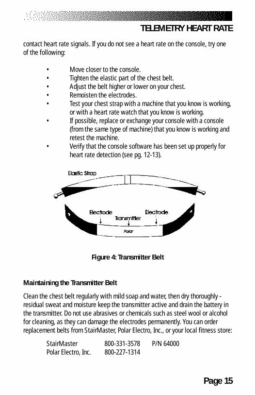
Figure 4: Transmitter Belt
Maintaining the Transmitter Belt
Clean the chest belt regularly with mild soap and water, then dry thoroughly -residual sweat and moisture keep the transmitter active and drain the battery inthe transmitter. Do not use abrasives or chemicals such as steel wool or alcoholfor cleaning, as they can damage the electrodes permanently. You can orderreplacement belts from StairMaster, Polar Electro, Inc., or your local fitness store:
StairMaster 800-331-3578 P/N 64000Polar Electro, Inc. 800-227-1314
TELEMETRY HEART RATE

Page 16
CONTACT HEART RATE
The StairMaster® Momentum features a digitized contact heart rate monitoringsystem. Through the use of stainless steel sensors built into the upper handlesand sophisticated software, heart rate can be checked at any time during aworkout. The heart rate is displayed on the console.
The contact heart rate system is very accurate (within 3% of themedical standard), but its ability to detect a heart rate signal is influenced byseveral factors. Movement of the muscles of the upper body produces anelectrical signal (muscle artifact) that will interfere with the detection of theheart rate signal by the sensors. Movement of the hands while they are incontact with the sensors also produces interference. Calluses and hand lotion actas an insulating layer to reduce the signal strength. Also, the EKG signal gener-ated by some individuals is not strong enough to be detected by the sensors.Typically, these individuals account for 5 - 7% of the population. These individu-als should opt for the Polar® chest strap method of heart rate monitoring. Mostpeople (between 93 – 95%) will not have a problem with the system providedinterference from movement is minimal.
Using Contact Heart Rate
Contact heart rate input signals are acquired only during contactbetween your hands and the stainless steel sensors on the handrails. To use thecontact heart rate feature, place your hands around the handles so that yourhands touch both the top and the bottom of the sensors. After the initial contactheart rate signal is detected, the console will enter a validation phase requiring agood heart beat signal within 10 to 15 seconds, or until the system acquires avalid signal. During the validation phase the console will not recognize telemetryheart rate signals. The console will display a beating double heart icon that hasthe inner heart colored in while searching for a valid signal. If, during exercise,the heart rate displayed is erratic, it may be helpful to remove your hands fromthe handles, wipe them and place them back on the handles. In all programs, theheart rate is shown automatically in the display window the first time thesensors are touched.
CONTACT HEART RATE
Page 17
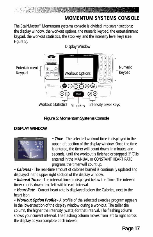
The StairMaster® Momentum systems console is divided into seven sections:the display window, the workout options, the numeric keypad, the entertainmentkeypad, the workout statistics, the stop key, and the intensity level keys (seeFigure 5).
Figure 5: Momentum Systems Console
DISPLAY WINDOW
• Time - The selected workout time is displayed in theupper left section of the display window. Once the timeis entered, the timer will count down, in minutes andseconds, until the workout is finished or stopped. If [0] isentered in the MANUAL or CONSTANT HEART RATEprogram, the timer will count up.
• Calories - The real-time amount of calories burned is continually updated anddisplayed in the upper right section of the display window.• Interval Timer - The interval timer is displayed below the Time. The intervaltimer counts down time left within each interval.• Heart Rate - Current heart rate is displayed below the Calories, next to theheart icon.• Workout Option Profile - A profile of the selected exercise program appearsin the lower section of the display window during a workout. The taller thecolumn, the higher the intensity (watts) for that interval. The flashing columnshows your current interval. The flashing column moves from left to right acrossthe display as you complete each interval.
MOMENTUM SYSTEMS CONSOLE
Display Window
EntertainmentKeypad
NumericKeypadWorkout Options
Workout Statistics Stop Key Intensity Level Keys
Page 18
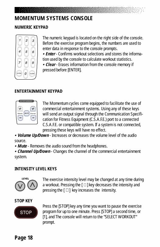
MOMENTUM SYSTEMS CONSOLENUMERIC KEYPAD
The numeric keypad is located on the right side of the console.Before the exercise program begins, the numbers are used toenter data in response to the console prompts.• Enter - Confirms workout selections and stores the informa-tion used by the console to calculate workout statistics.• Clear - Erases information from the console memory ifpressed before [ENTER].
ENTERTAINMENT KEYPAD
The Momentum cycles come equipped to facilitate the use ofcommercial entertainment systems. Using any of these keyswill send an output signal through the Communication Specifi-cation for Fitness Equipment (C.S.A.F.E.) port to a connectedC.S.A.F.E. or compatible system. If a system is not connected,pressing these keys will have no effect.
• Volume Up/Down - Increases or decreases the volume level of the audiosource.• Mute - Removes the audio sound from the headphones.• Channel Up/Down - Changes the channel of the commercial entertainmentsystem.
INTENSITY LEVEL KEYS
The exercise intensity level may be changed at any time duringa workout. Pressing the [ ∨ ] key decreases the intensity andpressing the [ ∧ ] key increases the intensity.
STOP KEYPress the [STOP] key any time you want to pause the exerciseprogram for up to one minute. Press [STOP] a second time, or[1], and The console will return to the "SELECT WORKOUT"prompt.

Page 19
MOMENTUM SYSTEMS CONSOLE
Workout Statistics
During the exercise program, the Stats keys are used to trackworkout statistics which are then shown in the display window.Pressing the [SELECT] key turns off the scanning feature andshows the statistic of choice in the display window. Pressing
the [SCAN] key will prompt the console to cycle through the following statistics:
• Distance - Provides a cumulative total of the equivalent distance, in miles (orkilometers if your console is set to metric units), you would have traveled whileriding a bicycle outdoors at the same relative intensity.• Calories/Hour - Provides a running total of the number of Calories burnedduring a workout.• RPM - Displays the revolutions per minute.• Speed - Displays the equivalent speed, in miles per hour (or kilometers perhour if your console is set to metric units), you would be traveling on a bicycleoutdoors while riding at the same relative intensity.• Intensity Level - Shows the current level between 1 (the easiest) and 20 (thehardest).• Watts - Displays the exercise intensity in watts (746 watts = 1 horsepower).• METs - Gives you the relative energy cost of exercise. MET stands formultiples of the resting metabolic rate. While you are sitting quietly, your bodyconsumes oxygen at the rate of about 3.5 milliliters per kilogram of body massper minute. When you exercise, your body needs more oxygen in order tofunction. For example, exercising at 10 METs requires ten times the resting rateof oxygen consumption, or about 35 milliliters per kilogram per minute. During aworkout, this key shows the current MET level. During the workout summary, theaverage MET level is displayed.• Target Heart Rate - Available only during the Constant Heart Rate program.Shows the selected target heart rate.
At the completion of a workout, the statistic averages are calculatedbased on the accumulation of data during the workout program, and notincluding the cool down period.
Page 20
MOMENTUM SYSTEMS CONSOLEEXERCISE PROGRAM KEYPAD
The exercise keypad is located below the display and to the left of the functionkeypad. While the console is in the “SELECT WORKOUT” mode, press one of theexercise program keys to preview the desired workout. There are sixworkout programs with the following standard defaults (pressing [ENTER]without inputting data first will prompt the console to enter these values):
• Weight - 175 lbs.• Intensity Level - 3• Workout Time - The default time in the programmed workouts
and Quick Start is 20 minutes. The Manual and Constant HeartRate programs do not have a specified default time. In theseprograms, the console timer will count up to the maximum time of99 minutes, and then return to 0.
• Age (Constant Heart Rate program only) - 40 years
Once you have selected a program, the prompts are:
• “ENTER WEIGHT - lbs” - type in your body weight inpounds (or kilograms if your console is set to metric units).
• “ENTER LEVEL 1 - 20” - select your intensity level withlevel 1 being the easiest and level 20 the hardest.
• “ENTER TIME 5 - 99” - select the workout duration in oneminute increments from 5 to 99. Press 0 in the MANUAL andCONSTANT HEART RATE program to workout for an unspecifiedamount of time.
The Quick Start Program
Provides an immediate start, without having to enter any user information. Thisprogram uses the standard default settings for derivation of calories burned.
The Manual Program
After pressing the [MANUAL] key, enter user and workout information. Beginexercising at the selected level. If desired, adjust the workout manually byusing the intensity level arrow keys. The profile in the display window isdivided into 15 equal intervals within the workout time. The profile is based
Page 21
MOMENTUM SYSTEMS CONSOLEon the selected intensity level, with 2 levels equating to one vertical bar.
The Fat Burner Program
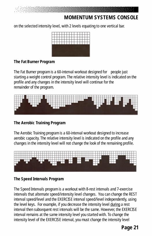
The Fat Burner program is a 60-interval workout designed for people juststarting a weight control program. The relative intensity level is indicated on theprofile and any changes in the intensity level will continue for theremainder of the program.
The Aerobic Training Program
The Aerobic Training program is a 60-interval workout designed to increaseaerobic capacity. The relative intensity level is indicated on the profile and anychanges in the intensity level will not change the look of the remaining profile.
The Speed Intervals Program
The Speed Intervals program is a workout with 8-rest intervals and 7-exerciseintervals that alternate speed/intensity level changes. You can change the RESTinterval speed/level and the EXERCISE interval speed/level independently, usingthe level keys. For example, if you decrease the intensity level during a restinterval then subsequent rest intervals will be the same. However, the EXERCISEinterval remains at the same intensity level you started with. To change theintensity level of the EXERCISE interval, you must change the intensity level
Page 22
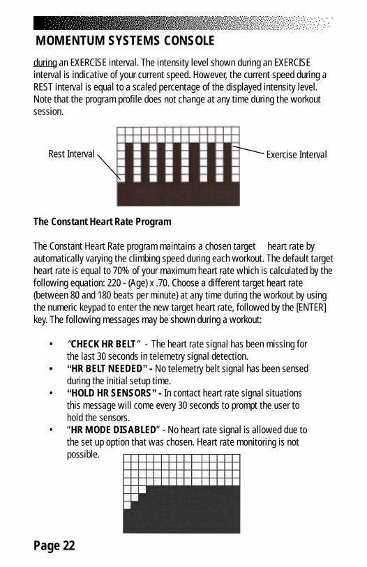
during an EXERCISE interval. The intensity level shown during an EXERCISEinterval is indicative of your current speed. However, the current speed during aREST interval is equal to a scaled percentage of the displayed intensity level.Note that the program profile does not change at any time during the workoutsession.
The Constant Heart Rate Program
The Constant Heart Rate program maintains a chosen target heart rate byautomatically varying the climbing speed during each workout. The default targetheart rate is equal to 70% of your maximum heart rate which is calculated by thefollowing equation: 220 - (Age) x .70. Choose a different target heart rate(between 80 and 180 beats per minute) at any time during the workout by usingthe numeric keypad to enter the new target heart rate, followed by the [ENTER]key. The following messages may be shown during a workout:
• “CHECK HR BELT” - The heart rate signal has been missing forthe last 30 seconds in telemetry signal detection.
• “HR BELT NEEDED” - No telemetry belt signal has been sensedduring the initial setup time.
• “HOLD HR SENSORS” - In contact heart rate signal situationsthis message will come every 30 seconds to prompt the user tohold the sensors.
• “HR MODE DISABLED” - No heart rate signal is allowed due tothe set up option that was chosen. Heart rate monitoring is notpossible.
MOMENTUM SYSTEMS CONSOLE
Rest Interval Exercise Interval
Page 23
MOMENTUM SYSTEMS CONSOLE
THE FITNESS TEST PROGRAMS
Understanding Submaximal Exercise Testing
Before using the StairMaster® Momentum for submaximal exercise testing, itshould be noted that all submaximal fitness tests make several assumptions:
• That a steady-state heart rate is obtained for each exerciseworkload.
• That a linear relationship exists between heart rate, oxygenuptake and workload.
• That the maximal heart rate for a given age is uniform.• That the mechanical efficiency of the physical activity performed
(i.e., oxygen uptake at a given workload) is the same foreveryone.
It should be kept in mind that any one or all of the above mentionedassumptions may not be met during a submaximal exercise test. If for anyreason one of the assumptions is not met, then errors in predicting VO2 max willoccur.
Unfortunately, it is often quite difficult to meet all of the requirementsfor the four listed assumptions. For example, exercising at a given workload foronly a few minutes can involve an insufficient amount of time for many individu-als to achieve a true steady-state. To ensure that a steady-state has beenachieved, the heart rate should be measured after two minutes of exercise at agiven workload and again after the third minute of exercise at that workload.These two heart rates should then be compared. If a difference of more than fivebeats per minute between the two is found, the subject should continue toexercise at one-minute intervals at the same workload until two successive heartrates differ by less than five beats per minute.
It is also important that the submaximal heart rates obtained bebetween 115 and 150 beats per minute, because it is within this heart rate rangethat a linear relationship tends to exist between heart rate and oxygen uptake orworkload for most adults. When the heart rate is less than 115, many externalfactors (e.g., talking, laughing, apprehension, etc.) can greatly influence heartrate. Once the heart rate reaches a level between 115 and 150, external factors

Page 24
MOMENTUM SYSTEMS CONSOLE
no longer influence heart rate, and a linear relationship exists. As the heart raterises above 150, the heart-rate/oxygen uptake relationship becomes curvilinear.
The third assumption involves maximal heart rate. Maximal heart rate isthe greatest heart rate that can be measured when an individual is exercising tothe point of volitional fatigue (i.e., exhaustion) during a graded exercise test.Several equations have been developed to estimate the average maximal heartrate for humans:
• Maximal heart rate = 220 minus age (low estimate)• Maximal heart rate = 210 minus [0.5 x age] (high estimate)• Maximal heart rate = 226 minus age (estimate for older
individuals)
Maximal heart rate can, however, vary greatly among differentindividuals of the same age. One standard deviation is ±12 bpm, which meansthat two-thirds of the population varies an average of plus or minus 12 heartbeats from the average given by a prediction equation. If an individual’s age-predicted maximal heart rate is higher than that person’s true maximal heart rate,then his/her estimated VO2 max will be an overestimation of the correct or actualvalue.
The final assumption addresses the issue of mechanical efficiency.Oxygen uptake at any given work rate can vary by approximately 15%between different individuals. Therefore, individuals vary in the amount ofoxygen they require to perform a certain exercise workload. Some individuals aremore efficient at performing a given task than others. As a result, the averageoxygen consumption associated with a given workload may vary significantlyfrom one person to another. Thus, VO2 max predicted by submaximal exercise teststends to be overestimated for those who are mechanically efficient and underes-timated for those who are inefficient.
The point to remember is that submaximal exercise testing, though notas precise as maximal exercise testing, is not without advantages. Forexample, the results of such testing can provide a fairly accurate reflection of anindividual’s fitness status without the cost, risk, effort (on the part of the subject)and time involved in max testing. If an individual is given repeated submaximalexercise tests and that person’s heart rate response to a fixed workload is found
Page 25
to decrease over time, it is reasonably safe to conclude that the individual hasmade improvements in aerobic (cardiorespiratory) fitness, irrespective of theaccuracy of the VO2 max prediction.
Pretest Screening
Prior to any exercise test (maximal or submaximal), participants should completea brief health/medical questionnaire, have their resting blood pressure and heartrate measured, and provide an informed consent form. The Physical ActivityReadiness Questionnaire (PAR-Q) is an example of a valid health/medicalquestionnaire for screening individuals prior to submaximal exercise testing.Canadian health and fitness practitioners have extensively (and quite success-fully) used the PAR-Q to determine whether individuals should be given anexercise test. A “yes” answer to any of the following seven questions taken fromthe PAR-Q would disqualify a participant from taking part in an exercise test untilappropriate medical clearance was obtained.
PHYSICAL ACTIVITY READINESS QUESTIONNAIRE (PAR-Q)
1. Has your doctor ever said you have a heart condition and recommendedonly medically supervised physical activity?
2. Do you have chest pain brought on by physical activity?3. Have you developed chest pain within the past month?4. Do you tend to lose consciousness or fall over as a result of dizziness?5. Do you have a bone or joint problem that could be aggravated by the
proposed physical activity?6. Has a doctor ever recommended medication for your blood pressure or a
heart condition?7. Are you aware, through your own experience or a doctor’s advice, of any
other physical reason against your exercising without medical supervi-sion?
The StairMaster Submaximal Fit Test
The StairMaster branching protocol is a series of 3-minute stages ofcontinuous exercise at increasing intensity. The first stage is a warmup atapproximately 4 METs. The intensity of the remaining stages is based on the
MOMENTUM SYSTEMS CONSOLE
Page 26
heart rate response to the warmup. The test is designed to raise the steady-state heart rate of the subject to 115 to 150 beats/min for two consecutivestages. It is important to remember that two consecutive heart rate measure-ments must be obtained in the 115 to 150 beats/min range to predict VO2max.The test typically lasts from 9 to 15 minutes.
In the StairMaster protocol, each work rate is performed for 3minutes, with heart rates recorded during the final 4 seconds of the 2nd and 3rd
minutes of each stage. If the heart rates are within 5 beats/min, then the heartrate during the last minute is plotted against the work rate, and the programadvances to the next 3-minute stage. The program continues for 2 to 4 stagesuntil 2 steady state heart rates between 115 to 150 beats/min are obtained in 2consecutive stages. The line generated from the plotted points is then extendedto the age-predicted maximal heart rate. A corresponding maximal work rate andVO2max can then be calculated.
At the end of the 3rd minute of each stage, if the heart rates at the endof the 2nd and 3rd minute are not within 5 beats/min of each other, then that workrate is maintained for an additional minute. At the end of the 4th minute, theheart rate is compared to the heart rate at the end of the 3rd minute. If the heartrates are within 5 beats/min, then the heart rate during the 4th minute is plottedagainst the work rate. If the heart rate at the end of the 3rd and 4th minute arenot within 5 beats/min, then the work rate is maintained for one more additionalminute. If the heart rate at the end of the 4th and 5th minutes are within 5 beats/min, then the heart rate at the end of the 5th minute is plotted against the workrate. If the heart rate at the end of the 4th and 5th minutes are not within 5 beats/min, then the test failed.
Once 2 consecutive heart rate measurements are obtained in the 115to 150 beats/min range, then the test ends successfully and the results aredisplayed. The estimated maximum aerobic capacity is shown in ml/kg/min andMETs. Next, the results are compared to normative values for others of the sameage range and gender (see Table 2). Results are stored in the console until thenext person starts an exercise program.
MOMENTUM SYSTEMS CONSOLE
Page 27
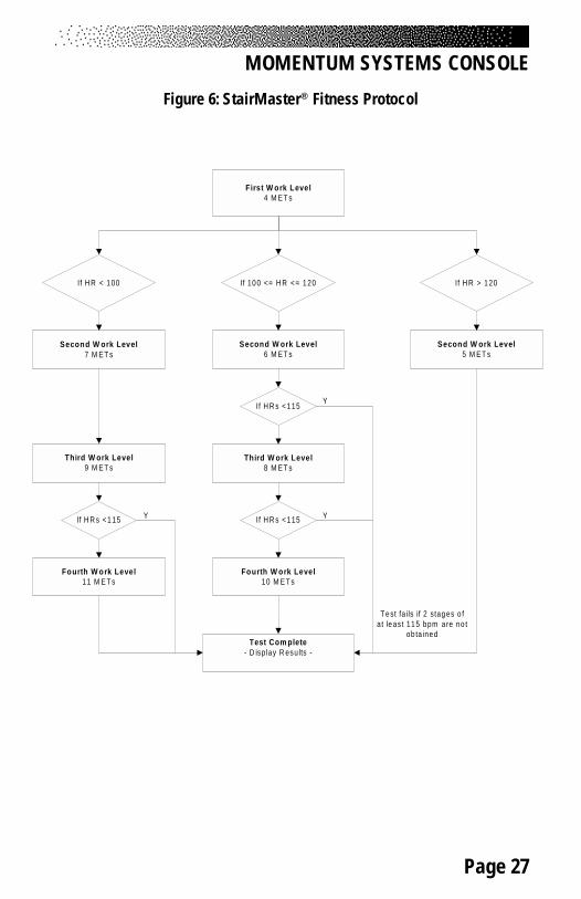
Figure 6: StairMaster® Fitness Protocol
MOMENTUM SYSTEMS CONSOLE
First W ork Level4 M ET s
If 100 <= H R <= 120If H R < 100 If H R > 120
Second W ork Level7 M ET s
Second W ork Level6 M ET s
Second W ork Level5 M ET s
Third W ork Level9 M ET s
Fourth W ork Level11 M E Ts
Third W ork Level8 M ET s
Fourth W ork Level10 M E Ts
Test Com plete- D isp lay R esults -
If H R s <115
If H R s <115If H R s <115
Y
YY
Test fa ils if 2 stages o fat least 115 bpm are no t
ob ta ined
Page 28
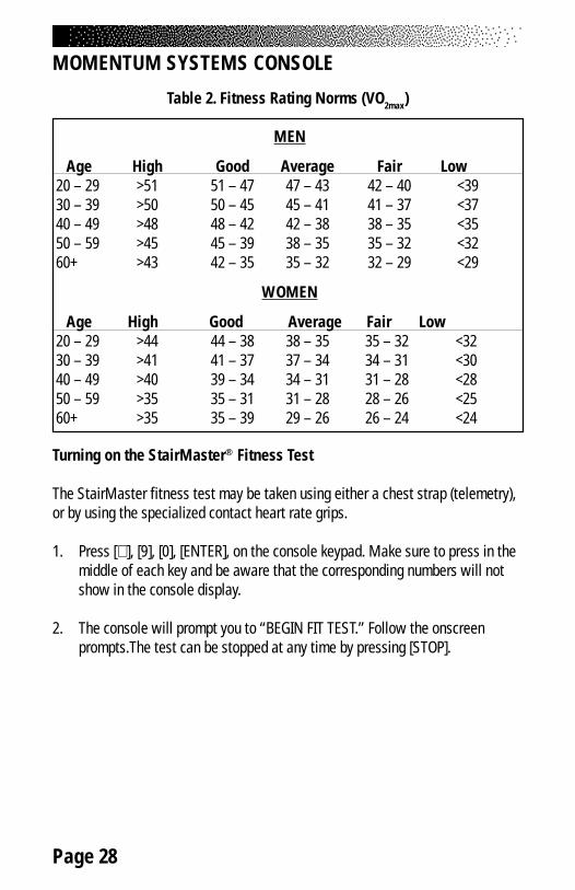
Table 2. Fitness Rating Norms (VO2max)
MEN
Age High Good Average Fair Low 20 – 29 >51 51 – 47 47 – 43 42 – 40 <39 30 – 39 >50 50 – 45 45 – 41 41 – 37 <37 40 – 49 >48 48 – 42 42 – 38 38 – 35 <35 50 – 59 >45 45 – 39 38 – 35 35 – 32 <32 60+ >43 42 – 35 35 – 32 32 – 29 <29
WOMEN
Age High Good Average Fair Low 20 – 29 >44 44 – 38 38 – 35 35 – 32 <32 30 – 39 >41 41 – 37 37 – 34 34 – 31 <30 40 – 49 >40 39 – 34 34 – 31 31 – 28 <28 50 – 59 >35 35 – 31 31 – 28 28 – 26 <25 60+ >35 35 – 39 29 – 26 26 – 24 <24
MOMENTUM SYSTEMS CONSOLE
Turning on the StairMaster® Fitness Test
The StairMaster fitness test may be taken using either a chest strap (telemetry),or by using the specialized contact heart rate grips.
1. Press [∧ ], [9], [0], [ENTER], on the console keypad. Make sure to press in themiddle of each key and be aware that the corresponding numbers will notshow in the console display.
2. The console will prompt you to “BEGIN FIT TEST.” Follow the onscreenprompts.The test can be stopped at any time by pressing [STOP].
Page 29
CONSOLE CODES
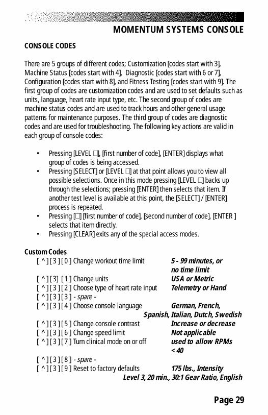
There are 5 groups of different codes; Customization [codes start with 3],Machine Status [codes start with 4], Diagnostic [codes start with 6 or 7],Configuration [codes start with 8], and Fitness Testing [codes start with 9]. Thefirst group of codes are customization codes and are used to set defaults such asunits, language, heart rate input type, etc. The second group of codes aremachine status codes and are used to track hours and other general usagepatterns for maintenance purposes. The third group of codes are diagnosticcodes and are used for troubleshooting. The following key actions are valid ineach group of console codes:
• Pressing [LEVEL ∧ ], [first number of code], [ENTER] displays whatgroup of codes is being accessed.
• Pressing [SELECT] or [LEVEL ∧ ] at that point allows you to view allpossible selections. Once in this mode pressing [LEVEL ∨ ] backs upthrough the selections; pressing [ENTER] then selects that item. Ifanother test level is available at this point, the [SELECT] / [ENTER]process is repeated.
• Pressing [∧ ] [first number of code], [second number of code], [ENTER ]selects that item directly.
• Pressing [CLEAR] exits any of the special access modes.
Custom Codes[ ^ ] [ 3 ] [ 0 ] Change workout time limit 5 - 99 minutes, or
no time limit[ ^ ] [ 3] [ 1 ] Change units USA or Metric[ ^ ] [ 3 ] [ 2 ] Choose type of heart rate input Telemetry or Hand[ ^ ] [ 3 ] [ 3 ] - spare -[ ^ ] [ 3 ] [ 4 ] Choose console language German, French,
Spanish, Italian, Dutch, Swedish[ ^ ] [ 3 ] [ 5 ] Change console contrast Increase or decrease[ ^ ] [ 3 ] [ 6 ] Change speed limit Not applicable[ ^ ] [ 3 ] [ 7 ] Turn clinical mode on or off used to allow RPMs
< 40[ ^ ] [ 3 ] [ 8 ] - spare -[ ^ ] [ 3 ] [ 9 ] Reset to factory defaults 175 lbs., Intensity
Level 3, 20 min., 30:1 Gear Ratio, English
MOMENTUM SYSTEMS CONSOLE
Page 30
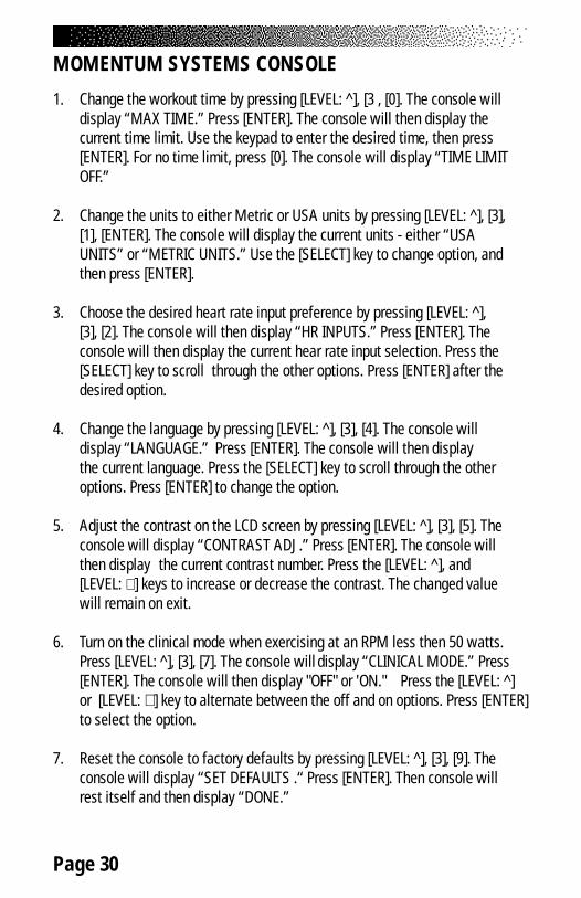
1. Change the workout time by pressing [LEVEL: ^], [3 , [0]. The console willdisplay “MAX TIME.” Press [ENTER]. The console will then display thecurrent time limit. Use the keypad to enter the desired time, then press[ENTER]. For no time limit, press [0]. The console will display “TIME LIMITOFF.”
2. Change the units to either Metric or USA units by pressing [LEVEL: ^], [3],[1], [ENTER]. The console will display the current units - either “USAUNITS” or “METRIC UNITS.” Use the [SELECT] key to change option, andthen press [ENTER].
3. Choose the desired heart rate input preference by pressing [LEVEL: ^],[3], [2]. The console will then display “HR INPUTS.” Press [ENTER]. Theconsole will then display the current hear rate input selection. Press the[SELECT] key to scroll through the other options. Press [ENTER] after thedesired option.
4. Change the language by pressing [LEVEL: ^], [3], [4]. The console willdisplay “LANGUAGE.” Press [ENTER]. The console will then displaythe current language. Press the [SELECT] key to scroll through the otheroptions. Press [ENTER] to change the option.
5. Adjust the contrast on the LCD screen by pressing [LEVEL: ^], [3], [5]. Theconsole will display “CONTRAST ADJ.” Press [ENTER]. The console willthen display the current contrast number. Press the [LEVEL: ^], and[LEVEL: ∨ ] keys to increase or decrease the contrast. The changed valuewill remain on exit.
6. Turn on the clinical mode when exercising at an RPM less then 50 watts.Press [LEVEL: ^], [3], [7]. The console will display “CLINICAL MODE.” Press[ENTER]. The console will then display "OFF" or 'ON." Press the [LEVEL: ^]or [LEVEL: ∨ ] key to alternate between the off and on options. Press [ENTER]to select the option.
7. Reset the console to factory defaults by pressing [LEVEL: ^], [3], [9]. Theconsole will display “SET DEFAULTS .“ Press [ENTER]. Then console willrest itself and then display “DONE.”
MOMENTUM SYSTEMS CONSOLE
Page 31
Machine Status Codes
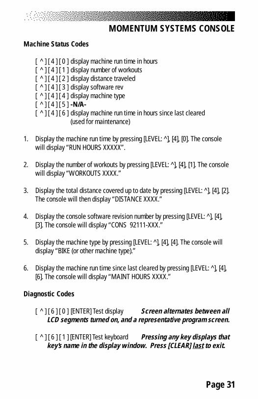
[ ^ ] [ 4 ] [ 0 ] display machine run time in hours[ ^ ] [ 4 ] [ 1 ] display number of workouts[ ^ ] [ 4 ] [ 2 ] display distance traveled[ ^ ] [ 4 ] [ 3 ] display software rev[ ^ ] [ 4 ] [ 4 ] display machine type[ ^ ] [ 4 ] [ 5 ] -N/A-[ ^ ] [ 4 ] [ 6 ] display machine run time in hours since last cleared
(used for maintenance)
1. Display the machine run time by pressing [LEVEL: ^], [4], [0]. The consolewill display “RUN HOURS XXXXX”.
2. Display the number of workouts by pressing [LEVEL: ^], [4], [1]. The consolewill display “WORKOUTS XXXX.”
3. Display the total distance covered up to date by pressing [LEVEL: ^], [4], [2].The console will then display “DISTANCE XXXX.”
4. Display the console software revision number by pressing [LEVEL: ^], [4],[3]. The console will display “CONS 92111-XXX.”
5. Display the machine type by pressing [LEVEL: ^], [4], [4]. The console willdisplay “BIKE (or other machine type).”
6. Display the machine run time since last cleared by pressing [LEVEL: ^], [4],[6]. The console will display “MAINT HOURS XXXX.”
Diagnostic Codes
[ ^ ] [ 6 ] [ 0 ] [ENTER] Test display Screen alternates between allLCD segments turned on, and a representative program screen.
[ ^ ] [ 6 ] [ 1 ] [ENTER] Test keyboard Pressing any key displays thatkey’s name in the display window. Press [CLEAR] last to exit.
MOMENTUM SYSTEMS CONSOLE
Page 32
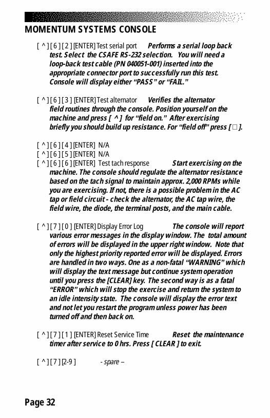
[ ^ ] [ 6 ] [ 2 ] [ENTER] Test serial port Performs a serial loop backtest. Select the CSAFE RS-232 selection. You will need aloop-back test cable (PN 040051-001) inserted into theappropriate connector port to successfully run this test.Console will display either “PASS” or “FAIL.”
[ ^ ] [ 6 ] [ 3 ] [ENTER] Test alternator Verifies the alternatorfield routines through the console. Position yourself on themachine and press [ ^ ] for “field on.” After exercisingbriefly you should build up resistance. For “field off” press [ ∨ ].
[ ^ ] [ 6 ] [ 4 ] [ENTER] N/A[ ^ ] [ 6 ] [ 5 ] [ENTER] N/A[ ^ ] [ 6 ] [ 6 ] [ENTER] Test tach response Start exercising on the
machine. The console should regulate the alternator resistancebased on the tach signal to maintain approx. 2,000 RPMs whileyou are exercising. If not, there is a possible problem in the ACtap or field circuit - check the alternator, the AC tap wire, thefield wire, the diode, the terminal posts, and the main cable.
[ ^ ] [ 7 ] [ 0 ] [ENTER] Display Error Log The console will reportvarious error messages in the display window. The total amountof errors will be displayed in the upper right window. Note thatonly the highest priority reported error will be displayed. Errorsare handled in two ways. One as a non-fatal “WARNING” whichwill display the text message but continue system operationuntil you press the [CLEAR] key. The second way is as a fatal“ERROR” which will stop the exercise and return the system toan idle intensity state. The console will display the error textand not let you restart the program unless power has beenturned off and then back on.
[ ^ ] [ 7 ] [ 1 ] [ENTER] Reset Service Time Reset the maintenancetimer after service to 0 hrs. Press [ CLEAR ] to exit.
[ ^ ] [ 7 ] [2-9 ] - spare –
MOMENTUM SYSTEMS CONSOLE
Page 33
MOMENTUM SYSTEMS CONSOLE
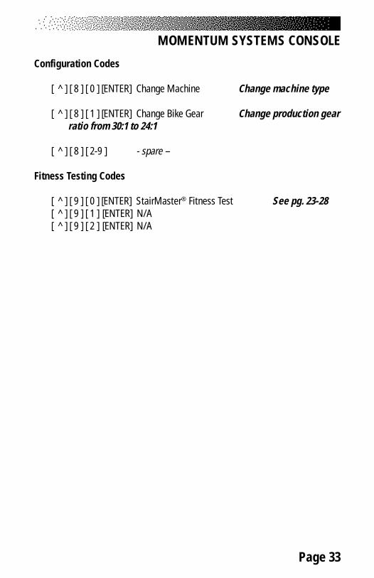
Configuration Codes
[ ^ ] [ 8 ] [ 0 ] [ENTER] Change Machine Change machine type
[ ^ ] [ 8 ] [ 1 ] [ENTER] Change Bike Gear Change production gearratio from 30:1 to 24:1
[ ^ ] [ 8 ] [ 2-9 ] - spare –
Fitness Testing Codes
[ ^ ] [ 9 ] [ 0 ] [ENTER] StairMaster® Fitness Test See pg. 23-28[ ^ ] [ 9 ] [ 1 ] [ENTER] N/A[ ^ ] [ 9 ] [ 2 ] [ENTER] N/A
Page 34
MAINTENANCE INSTRUCTIONS
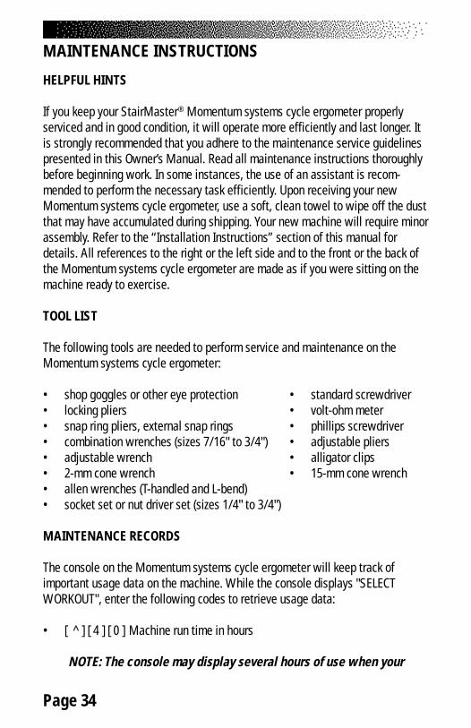
HELPFUL HINTS
If you keep your StairMaster® Momentum systems cycle ergometer properlyserviced and in good condition, it will operate more efficiently and last longer. Itis strongly recommended that you adhere to the maintenance service guidelinespresented in this Owner’s Manual. Read all maintenance instructions thoroughlybefore beginning work. In some instances, the use of an assistant is recom-mended to perform the necessary task efficiently. Upon receiving your newMomentum systems cycle ergometer, use a soft, clean towel to wipe off the dustthat may have accumulated during shipping. Your new machine will require minorassembly. Refer to the “Installation Instructions” section of this manual fordetails. All references to the right or the left side and to the front or the back ofthe Momentum systems cycle ergometer are made as if you were sitting on themachine ready to exercise.
TOOL LIST
The following tools are needed to perform service and maintenance on theMomentum systems cycle ergometer:
• shop goggles or other eye protection • standard screwdriver• locking pliers • volt-ohm meter• snap ring pliers, external snap rings • phillips screwdriver• combination wrenches (sizes 7/16" to 3/4") • adjustable pliers• adjustable wrench • alligator clips• 2-mm cone wrench • 15-mm cone wrench• allen wrenches (T-handled and L-bend)• socket set or nut driver set (sizes 1/4" to 3/4")
MAINTENANCE RECORDS
The console on the Momentum systems cycle ergometer will keep track ofimportant usage data on the machine. While the console displays "SELECTWORKOUT", enter the following codes to retrieve usage data:
• [ ^ ] [ 4 ] [ 0 ] Machine run time in hours
NOTE: The console may display several hours of use when your

Page 35
MAINTENANCE INSTRUCTIONS
machine first arrives due to testing at the manufacturing facility.
• [ ^ ] [ 4 ] [ 1 ] Number of workouts• [ ^ ] [ 4 ] [ 2 ] Distance traveled• [ ^ ] [ 4 ] [ 3 ] Software revision number• [ ^ ] [ 4 ] [ 4 ] Machine type• [ ^ ] [ 4 ] [ 5 ] -N/A-• [ ^ ] [ 4 ] [ 6 ] Machine maintenance run time in hours since last cleared
NOTE: There are 2 timers in the console; one for machine run timetotal and one for tracking machine run time since last serviced.
Resetting the Maintenance Hour Timer
After each maintenance period reset the counter.
[ ^ ] [ 7 ] [ 1 ] Reset Service
1. Reset the maintenance hour counter by pressing [LEVEL: ^], [7], [1]. Theconsole will display “RESET SERVICE.” Press [ENTER]. The console willdisplay “DONE.” Press [CLEAR] to return to the starting screen.
PREVENTIVE MAINTENANCE
The procedures for performing recommended preventive maintenance on theMomentum systems cycle ergometer are summarized in Table 5.
Cleaning
1. DO NOT USE GLASS CLEANER OR ANY OTHER HOUSEHOLDCLEANERS ON THE CONSOLE. Clean the console daily with a water-dampened cloth and wipe dry after cleaning.
2. Clean the exterior covers, the pedals, and the seat on a weeklybasis using either soap and water or a diluted, non-mineral basedhousehold cleaner such as Fantastic®.

Page 36
MAINTENANCE INSTRUCTIONS
Weekly Inspection
1. Frame: Inspect the painted surfaces of the exposed frame for any rust,bubbling, or chips during the weekly cleaning. The salt in perspirationwill damage unpainted surfaces. Repair the damaged area with atouch-up paint kit provided by StairMaster® Health & Fitness Products,Inc. (part number 22181).
2. Pedals: Inspect the pedal foot straps at both the inside and outsideattachment sites. Replace the foot straps if they are torn or ripped.
3. Seat:3400 CE : Inspect the seat post and the seat adjustment pin. Theseat post should slide up and down freely in the plastic collar with theadjustment pin pulled out. Clean the seat post of any accumulatedgrime with a clean rag. The seat adjustment pin should completelyengage the holes in the seat post. If the seat adjustment pin springaction is sticky, apply a few drops of 30W motor oil, or the equivalentlubricant, to the pin shaft.
3800 RC: Inspect the seat assembly movement to ensure that the seatmoves freely on the seat track. Note that the center wheel on each sideof the seat assembly is eccentric. These wheels are adjustable byloosening the nut, turning the wheel to adjust the height, and thentightnening the nut. If necessary, adjust these two wheels to allow theseat assembly to move freely on the seat track.
Monthly Inspection
1. Pedal crank: Inspect the crank bearings for either excessive play ortightness. Either condition will reduce the life of the bearings. Ensurethe bearing clamps are tight. Refer to the “Part Removal andReplacement” section of this manual for the proper adjustmentprocedures.
2. Belts: Inspect the HTD and Poly-V belt for excessive wear. Adjust thebelt tension if necessary.HTD Belt: Adjust the HTD belt tension to allow 1/2" of belt deflectionwith fingertip pressure between the idler pulley and the HTD sprocket.
Page 37
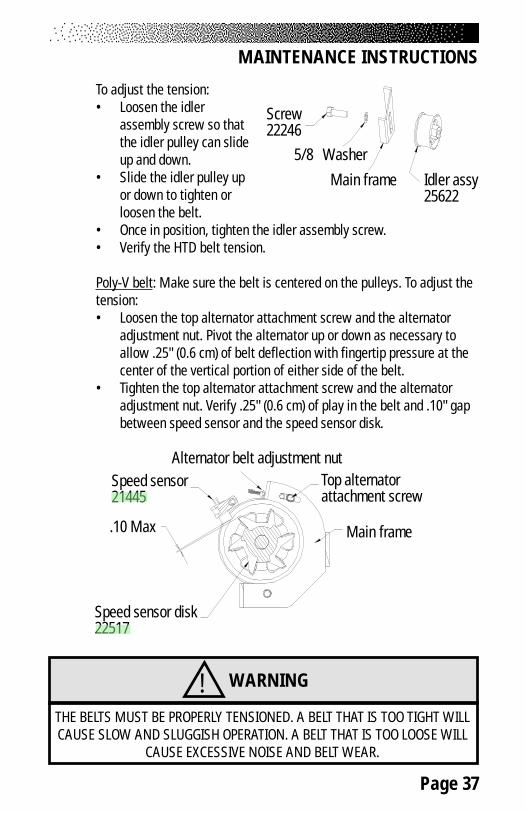
MAINTENANCE INSTRUCTIONS
To adjust the tension:• Loosen the idler
assembly screw so thatthe idler pulley can slideup and down.
• Slide the idler pulley upor down to tighten orloosen the belt.
• Once in position, tighten the idler assembly screw.• Verify the HTD belt tension.
Poly-V belt: Make sure the belt is centered on the pulleys. To adjust thetension:• Loosen the top alternator attachment screw and the alternator
adjustment nut. Pivot the alternator up or down as necessary toallow .25" (0.6 cm) of belt deflection with fingertip pressure at thecenter of the vertical portion of either side of the belt.
• Tighten the top alternator attachment screw and the alternatoradjustment nut. Verify .25" (0.6 cm) of play in the belt and .10" gapbetween speed sensor and the speed sensor disk.
Idler assy25622
Main frame
5/8 Washer
Screw22246
! WARNING
THE BELTS MUST BE PROPERLY TENSIONED. A BELT THAT IS TOO TIGHT WILLCAUSE SLOW AND SLUGGISH OPERATION. A BELT THAT IS TOO LOOSE WILL
CAUSE EXCESSIVE NOISE AND BELT WEAR.
Speed sensor21445
Speed sensor disk22517
.10 Max Main frame
Alternator belt adjustment nutTop alternatorattachment screw

Page 38
MAINTENANCE INSTRUCTIONS
Table 5. Preventive Maintenance Schedule
TRAP DEDNEMMOCERNOITCA YCNEUQERF RENAELC
elosnoC naelcepiW yliaD retaW
srevoC naelcepiW yliaD
&paoS,retawdetulid
dlohesuohrenaelc
taeS naelC
,keewhcaEretfaro07yreve
esufosruoh
&paoS,retawdetulid
dlohesuohrenaelc
&sladePspartstoof tcepsni&naelC
,keewhcaEretfaro07yreve
esufosruoh
&paoS,retawdetulid
dlohesuohrenaelc
tsoptaeSEC0043 tcepsni&naelC
,keewhcaEretfaro07yreve
esufosruoh
yrd,naelCgar
kcarttaeSCR0083 tcepsni&naelC
,keewhcaEretfaro07yreve
esufosruoh
yrd,naelCgar
knarCsgniraeb tcepsnI
,htnomhcaE003ro
sruohA/N
stleB tcepsnI,htnomhcaE
003rosruoh
A/N

Page 39
TROUBLESHOOTINGGENERAL TROUBLESHOOTING GUIDELINES
This section outlines several tests to systematically identify and isolate problemswith the electrical system and the drive train. This troubleshooting section isorganized into three basic problem sections: Electrical System, ConsoleDiagnostics, and the Drive Train. Perform the tests in exactly the same order aswritten. Refer to the “Parts Removal and Replacement” section of this manualfor any disassembly and assembly instructions. To order a replacement part, or toget help with the troubleshooting process, contact the Customer Service Depart-ment of StairMaster Health & Fitness Products, Inc. at (800) 331-3578.International customers should contact their local distributor or call(425) 823-1825.
SYSTEMATIC ELECTRICAL TROUBLESHOOTING
The electrical system of your Momentum systems cycle ergometer has five majorcomponents: the power control board, the alternator, the load resistor, the maincable assembly, and the console. In order to identify the component that iscausing the problem, you must systematically test the entire system. You willneed a Volt-Ohm meter (multimeter) and alligator clips to conduct portions of thefollowing procedures. The console, battery, and power control board are notserviceable by the owner. If any of these parts are inoperable, they must bereplaced. Attempted repairs to the console, battery, or the power control boardwill void the warranty.
1. Remove the side covers.
2. Test the battery connection at the power control board (PCB). MeasureVDC between yellow test points 7 and 10 (near the battery connector) ofthe PCB for a minimum of 6.0 VDC. If the measured voltage is 6.0 VDC ormore, skip to step 6.
3. Test the battery. Unplug the battery connector from the power controlboard and locate pin 2 and pin 3 in the end of the battery connector.
4. Use a voltmeter to verify that the voltage between pin 2 (negative) andpin 3 (positive) is a minimum of 6.0 VDC. Install the battery charger forat least 24 to 48 hours if the voltage measured is below 6.0 VDC. It is
Page 40
SYSTEMATIC ELECTRICAL TROUBLESHOOTING
okay to use the machine with the battery charger connected. After 48hours, repeat step 3 - 4. If the voltage measured is below 6.0 VDC thenthe battery is bad.
5. Plug the battery connector back into the power control board.
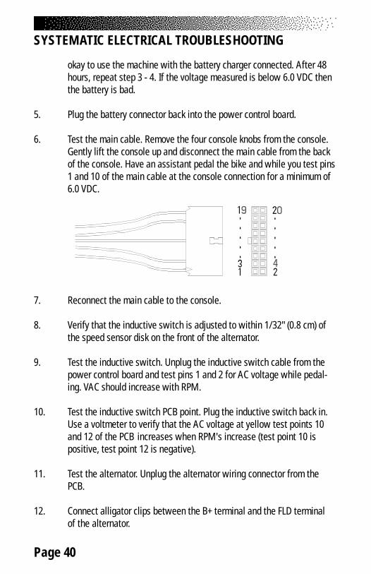
6. Test the main cable. Remove the four console knobs from the console.Gently lift the console up and disconnect the main cable from the backof the console. Have an assistant pedal the bike and while you test pins1 and 10 of the main cable at the console connection for a minimum of6.0 VDC.
7. Reconnect the main cable to the console.
8. Verify that the inductive switch is adjusted to within 1/32" (0.8 cm) ofthe speed sensor disk on the front of the alternator.
9. Test the inductive switch. Unplug the inductive switch cable from thepower control board and test pins 1 and 2 for AC voltage while pedal-ing. VAC should increase with RPM.
10. Test the inductive switch PCB point. Plug the inductive switch back in.Use a voltmeter to verify that the AC voltage at yellow test points 10and 12 of the PCB increases when RPM's increase (test point 10 ispositive, test point 12 is negative).
11. Test the alternator. Unplug the alternator wiring connector from thePCB.
12. Connect alligator clips between the B+ terminal and the FLD terminalof the alternator.
Page 41
SYSTEMATIC ELECTRICAL TROUBLESHOOTING
13. Pedal the cycle at a high RPM rate for 10-15 seconds or until you feelthe resistance level change making it harder to pedal. If no resistance isfelt then the alternator has a problem.
14. Test the diode. Unplug the diode from the FLD terminal of the alternator.
15. Use a voltmeter, set to Ohms to test the diode. A good diode will showa high resistance reading in one direction and a low resistancereading when the voltmeter leads are reversed.
16. Reconnect the diode to the FLD terminal of the alternator.
17. Reconnect the alternator wiring connector to the power control board.
18. Test the load resistor. Unplug the load resistor from the power controlboard and locate pin 1 and pin 2 at the end of the cable.
19. Use a voltmeter, set to Ohms to test the load resistor for a correctreading of 1/2 Ohm between pins 1 and 2.
20. Plug the load resistor back into the power control board.
21. Check the main cable assembly for continuity and cross checkeach wire in the cable to check for shorted wires. Call StairMaster®
Customer Service at (800) 331-3578 for assistance. Internationalcustomers should contact their local distributors.
Page 42
SYSTEMATIC MECHANICAL TROUBLESHOOTING
SYSTEMATIC MECHANICAL TROUBLESHOOTING
These steps should be performed in exactly the order written. Refer to the "PartsRemoval and Replacement" section of this manual for any disassembly andassembly instructions.
1. Remove the side covers.
2. Adjust the HTD belt so that the belt is positioned centered on the largeHTD pulley and the idler pulley assembly. Verify that the belt istensioned so that it is tight enough that it does not ride off, and looseenough that it doesn't bind the pulleys. Retest the machine if HTD beltadjustment was necessary.
3. Verify that the jam nut and bearing nut assemblies on the crankassembly are tight.
4. Spin the crank assembly with the belt removed and listen for anyclicking or grinding noises. The crank should spin freely 4 or 5revolutions. Resume troubleshooting at step 6 if no noises are heard.
5. Verify that the jam nut on the flywheel and the alternator is tight.
6. Adjust the speed sensor to .10" from the speed sensor disk.
7. Spin the alternator/flywheel assembly and listen for clicking and/orgrinding noises.
8. With the Poly-v belt removed, inspect the Poly-V pulley for excess wearand spin the pulley to check the Poly-V bearings.
9. Disassemble the intermediate shaft assembly and inspect theintermediate shaft for wear.
10. Inspect the Poly-V belt for wear.
11. Contact our Customer Service Department or your local distributor forassistance. Refer to the Appendix for the appropriate phone number.
Page 43
The following tests are performed while the console is in the “SELECTWORKOUT” mode. If the console fails any test, the console should be replaced orexchanged. To return to the “SELECT WORKOUT” mode, press either [CLEAR] or[STOP] while in the DIAGNOSTIC mode. Please note that there may be additionverbiage on the display other than is listed in this manual. The Momentumconsole is used on other StairMaster® equipment.
Diagnostic Codes
[ ^ ] [ 6 ] [ 0 ] Test display[ ^ ] [ 6 ] [ 1 ] Test keyboard[ ^ ] [ 6 ] [ 2 ] Test serial port[ ^ ] [ 6 ] [ 3 ] Test alternator[ ^ ] [ 6 ] [ 4 ] -N/A-[ ^ ] [ 6 ] [ 5 ] -N/A-[ ^ ] [ 6 ] [ 6 ] Test Tach[ ^ ] [ 6 ] [ 7 ] - [ 6 ] [ 9 ] -N/A-
Display Test
During the display test, the console screen alternates between all LCD segmentsturned on, and sample program profile screen at a 2-second rate.
1. Press [ LEVEL: ^ ], [ 6 ], [ 0 ], [ENTER]. The console will display“DISPLAY TEST”.
2. All LCD segments will turn on for 2 seconds and then a sampleprogram profile will be displayed for 2 seconds. Press [CLEAR] to endthe test.
Keypad Test
Perform this test if you are having trouble entering data into the console.During the test, pressing any key displays that key name on the message line.Press [CLEAR] to exit.
1. Press [ LEVEL: ^ ], [ 6 ], [ 1 ], to start the test.
CONSOLE DIAGNOSTIC TESTS

Page 44
2. Firmly press each button except [CLEAR]. The name of the key will beshown in the display window. Press [CLEAR] to end the test.
Serial Port Test
This test verifies that the RS 232 port used for linking to commercial entertain-ment systems is working. You must have the loop-back cable assembly, pn040051-001 to perform this test.
1. Insert the loop-back cable assembly into the RS 232 port on the backof the console.
2. Press [ LEVEL: ^ ], [ 6 ], [ 2 ], [ENTER] to start the test.
3. The console will run a diagnostic test and then display either “PASS”or “FAIL.” Replace the console if it fails this test.
Alternator Test
Use this test to verify the alternator field routines of the console. You will needto briefly exercise on the machine for this test.
1. Press [ LEVEL: ^ ], [ 6 ], [ 3 ], to start the test.
2. For “Field on” press [ LEVEL: ^]. Step on the machine forapproximately 10 to 15 seconds. If full resistance is achieved duringthis time, your console has correct current flow. If no resistance isachieved, either the console or the alternator is bad. See theelectrical troubleshooting portion of this manual to isolate and testthe alternator. Replace the console if the alternator is good.
3. For ‘Field off” press [ LEVEL: V]. Step on the machine forapproximately 10 to 15 seconds. You should not get resistance withthe field turned off. Press [CLEAR] to end the test.
CONSOLE DIAGNOSTIC TESTS
Page 45
CONSOLE DIAGNOSTIC TESTS
Tach Test
If you do not have resistance, perform the tach test. The tach test will tell you thetach signal, in revolutions per minute (RPMs), picked up by the console.
1. Press [ LEVEL: ^ ], [ 6 ], [ 6 ], [ENTER]. The console will display“TAR TACH ACT”. The target tach speed of 2000 RPMs will be shownin the upper left corner of the display window. The actual tach pickedup by the console will be shown in the upper right corner of thedisplay window.
2. Start stepping on the pedals. The number in the right hand corner ofthe console should increase to 2000 RPMs (+/- 200). If the tach signalpicked up by the console is less then 1900 RPMs then there is aproblem in the AC tach circuit - either with the console software,alternator (check the AC tach wire, the field wire, the diode, and theterminal posts), or the main cable.
Error Reporting
The console will display various error messages in the display window. The totalamount of errors will be displayed in the upper right numeric window. Note thatonly the highest priority reported error will be displayed. Errors are handled intwo ways. One as a non-fatal “WARNING” which will display the text messagebut continue system operation until the user presses the [CLEAR] key. Thesecond way is as a fatal “ERROR” which will stop the exercise and return thesystem to an idle intensity state. The console will display the error text and notlet the user restart the programs unless power has been turned off and then backon.
The following microprocessor errors require a console replacement;ALU ERROR, TIMER ERROR, and STATIC RAM ERROR.
Resetting the power may clear the following microprocessor errors; EEPROMERROR, and PROGRAM ERROR. If resetting the power doesn’t work, the consolemay need to be replaced.
Page 46
Contact Heart Rate Test
The contact heart rate system is made up of the console and the contactheart rate sensor handles. Remember that even when operating properly, thecontact Heart Rate system will not work for everyone. If you suspect you have aproblem with your system, have someone else try it before performing thefollowing troubleshooting steps:
1. With the console showing “SELECT WORKOUT”, place your handson the sensor handles using a relaxed grip, and remain still. Afterapproximately 10 seconds a flashing ♥ should be displayed on theconsole, followed by your heart rate in beats per minute. If your heartrate does not appear, continue on to the next step.
2. Verify that the console software has been set up to receive contactheart rate (see heart rate monitoring section of this manual).
3. If the telemetry (Polar®) receiver located in the console is receivinginterfering signals, the contact heart rate system may be inhibited.Take your hands off the handle sensors for about 20 seconds andwatch the heart display. If it flashes on and off, the telemetry heartrate is picking up interfering signals, and the machine must be movedaway from the source of the interference or the telemetry heart rateinput must be disabled (see heart rate monitoring section of thismanual).
4. Remove the console knobs from the back of the console, lift theconsole up, and disconnect both the main cable and the small handgrip sensor cable from the console. Use an Ohmmeter to check forcontinuity between the hand grip sensors and the small cableconnector. If the handles are working, each steel sensor should beconnected to one wire on the cable connector, with less than 15 ohmsshowing on the ohmmeter.
5. If possible, replace or exchange your console with a console that youknow is working and retest the machine.
6. f the problem still persists, contact the Customer Service Departmentat 800-331-3578.
CONSOLE DIAGNOSTIC TESTS
Page 47
CONSOLE DIAGNOSTIC TESTS
Telemetry (Polar®) Heart Rate Test
The telemetry heart rate system is made up of the console, the heart ratereceiver, and the chest strap (available separately). You can test each componentby performing the following steps:
1. You will need to put a chest strap on in order to test the telemetryheart rate. Before you put on the chest strap, wet the two contactpatches. Secure the chest strap as high under your pectoral muscles(chest) as is comfortable. The chest strap should fit snugly,comfortably, and allow normal breathing.
2. A flashing ♥ should be displayed on the console. Your heart rate, inbeats per minute, will show next to the heart icon. If the heart icondoes not show, or if your heart rate is not displayed on the consolethen you have a problem with either the console, chest strap, orheart rate receiver.
3. Verify that the console software has been set up to receive telemetry(see the heart rate monitoring section of this manual). Note thatholding the contact heart rate sensors (if enabled) can inhibit thetelemetry heart rate input from working.
4. Test your chest strap with a machine that you know is working, orwith a heart rate watch that you know is working.
5. External interference caused by nearby televisions, personal CDplayers, or air conditioners may also inhibit the telemetry heart ratepickup. Move the machine away from interference sources if possible.
6. If possible, replace or exchange your console with a console that youknow is working and retest the machine.
7. Visually check that the heart rate receiver is positioned correctly inthe neck cover. The heart rate receiver jack should point down.Ensure that the heart rate receiver is connected to the console, andthat the connection is not loose. If possible, swap the heart ratereceiver with one from a machine that is working.
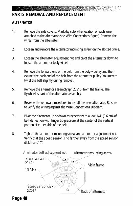
Page 48
PARTS REMOVAL AND REPLACEMENT
ALTERNATOR
1. Remove the side covers. Mark (by color) the location of each wireattached to the alternator (see Wire Connections figure). Remove thewires from the alternator.
2. Loosen and remove the alternator mounting screw on the slotted brace.
3. Loosen the alternator adjustment nut and pivot the alternator down toloosen the alternator (poly-v) belt.
4. Remove the forward end of the belt from the poly-v pulley and thenextract the back end of the belt from the alternator pulley. You may totwist the belt slightly during removal.
5. Remove the alternator assembly (pn 25815) from the frame. Theflywheel is part of the alternator assembly.
6. Reverse the removal procedures to install the new alternator. Be sureto verify the wiring against the Wire Connections Diagram.
7. Pivot the alternator up or down as necessary to allow 1/4" (0.6 cm) ofbelt deflection with finger tip pressure at the center of the verticalportion of either side of the belt.
8. Tighten the alternator mounting screw and alternator adjustment nut.Verify that the speed sensor is no farther away from the speed sensordisk than .10".

Page 49
COVERS
The Momentum 3400 CE / 3800 RC cycle ergometer is protected by two largeside covers.
1. If connected, disconnect the battery charger from the connector locatedon the back right side cover.
2. Use a phillips screwdriver to remove the screws, washers, and nutsfrom the side covers by the seat post.
3. The side covers are held in place with seven reusable fasteners. Use thefastener removal tool (included with each machine) to remove thefasteners. Slide either end of the fastener removal tool under the edgeof the inner head pin and pull the pin out about halfway. The inner headpin should not be pulled out of its base. Remove the fastener from thecover and set aside.
PARTS REMOVAL AND REPLACEMENT
! WARNING
TO REDUCE THE RISK OF INJURY, DO NOT OPERATE THE MACHINEWHILE THE COVERS ARE REMOVED. DO NOT ROTATE THE PEDALS WHILE
ANYONE'S HANDS ARE INSIDE THE MACHINE.
Page 50
PARTS REMOVAL AND REPLACEMENT
4. Move the crank to about the eleven o’clock position on the left sideto get the left side cover over the crank and off the machine. Once theleft cover is off the frame, move the cranks to the one o’clock positionon the right side and remove the right cover.
5. To reinstall the cover fasteners, insert the fastener base through thecover and into the frame. When the base is in place, push the headpin in all the way to secure the fastener. If necessary, connect thebattery charger to the power connector once the side covers areattached.
CONSOLE
1. Unscrew the four console mounting knobs from the back of the console.
2. Gently lift the console up a few inches and disconnect the main cableand contact heart rate cables from the back of the console. Remove theconsole from the machine.
3. Reverse the steps to reinstall the console.
HANDLEBAR ASSEMBLY (3400 CE)
1. Remove the console.
2. Tilt the machine back and rest it on its seat, upside down. The handlebars should now be in the air and allow easy access to the mountingscrews and the main cable.
3. Gently pull the main cable out from the frame tube. The main cable issectioned into two parts with quick release connectors attached.Disconnect each section of main cable to allow removal of handlebars.
4. Loosen and remove the four screws and flat washers from the mainframe.
5. Hold onto the handlebars and pull the handlebar assembly out from themain frame.
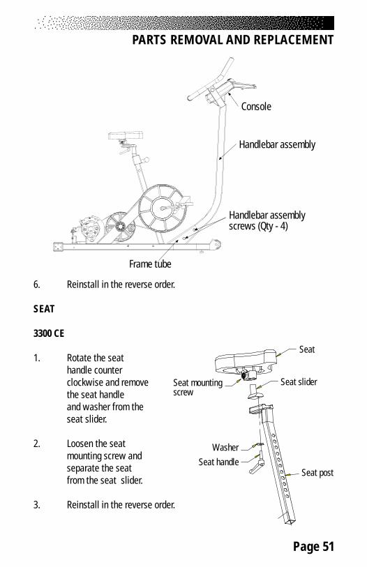
Page 51
PARTS REMOVAL AND REPLACEMENT
6. Reinstall in the reverse order.
SEAT
3300 CE
1. Rotate the seathandle counterclockwise and removethe seat handleand washer from theseat slider.
2. Loosen the seatmounting screw andseparate the seatfrom the seat slider.
3. Reinstall in the reverse order.
Handlebar assemblyscrews (Qty - 4)
Frame tube
Handlebar assembly
Console
Seat
Seat slider
Washer
Seat handleSeat post
Seat mountingscrew
Page 52
PARTS REMOVAL AND REPLACEMENT
3900 RC
The seat pads can be removed while the seat is in the seat track. Pop off thefinishing cap with a flat blade screwdriver, and then loosen and remove the fourmounting bolts from each seat pad and lift the pad free. To remove the seat fromthe seat track:
1. Loosen and remove the nyloc nut and flat washer from the rear of theseat track. Remove the bolt.
2. Remove the seat track cover.
3. Lift the seat adjustment handle and slide the seat to the rear and offthe track.
4. To reinstall the seat, line up the front guide wheels with the seattrack. Carefully slide the seat forward while holding up on the seatadjustment handle until all six wheels are in the seat track.
5. Verify proper operation of the seat adjustment handle beforeinstalling the seat track cover.
6. Install the bolt through the seat track and track cover. Install andsecurely tighten the flat washer and the nyloc nut.
7. The seat track play can be adjusted by loosening the nut on bothcenter wheels of the seat assembly while using a standard screwdriverto turn the bolt. Ideally, the seat should slide easily without excessiveside play. Tighten the nuts after the wheels are adjusted.

Page 53
SEAT POST (3400 CE)
1. Unsnap the seat post cover cap from the frame by pulling up on thebottom edges of the cover cap. Allow the seat post cover cap to restfreely on the seat post.
2. Rotate the seat handle counterclockwise to until it is unthreaded fromthe seat.
3. Remove the seat and seat slider from the seat post.
4. Pull the seat adjustment knob out, lift the seat post up, and remove theseat post from the frame.
5. Reverse the steps to reinstall the seat post in the frame.
PARTS REMOVAL AND REPLACEMENT
Seat
Seat slider
WasherSeat handle
Seat post
Spring clip
Seat post cover cap
Seat post end cap
Screw

Page 54
SEAT HANDLE (3400 CE)
1. Rotate the seat handle counterclockwise until it is unthreaded from theseat. Remove the seat handle and washer from the seat slider.
2. On the replacement handle, apply a thin layer of grease on the threadsfrom half way to the end of the threads. Install the washer on thehandle and thread the new handle halfway into the seat. Position theseat in the desired location. Rotate the handle clockwise to secure theseat.
3. Ensure that the handle does not stick out to the right or left. Thehandle is spring loaded so that you can properly align the frame andthe handle. Simply pull out on the handle and rotate it for correctalignment.
SEAT TRACK (3800 RC)
1. Remove the side covers and remove the seat assembly from the seattrack.
2. Using a 5/16" allen wrench, loosen and remove the three screws and sixwashers that fasten the seat track to the main frame. Remove the seattrack from the frame. Reverse the steps to reinstall the seat track.
PARTS REMOVAL AND REPLACEMENT

Page 55
PARTS REMOVAL AND REPLACEMENT
HIGH TORQUE DRIVE (HTD) BELT
1. Remove both side covers.
2. Loosen the idler assembly screw and slide the pulley down, looseningthe belt.
3. Pull the belt off the large HTD sprocket slide it over the right crank arm.Remove the belt from the small HTD sprocket.
4. Reverse the steps to install the belt.
5. Check the tension in the drive belt.
6. To adjust the belt tension, slide the idler pulley up or down asnecessary. Tighten the idler assembly nut and recheck the belttension. Readjust the belt tension if necessary.
7. Reinstall the covers.
POLY-V BELT
1. Loosen the alternator adjustment nut and the alternator mountingscrew. Pivot the alternator down to loosen the poly-v belt.
2. Remove the forward end of the belt from the poly-v pulley and thenextract the back end of the belt from the alternator pulley. You may totwist the belt slightly during removal.
3. Center the new belt on the two pulleys and pivot the alternatorup as necessary to allow .25" (0.6 cm) of belt deflection with fingertippressure at the center of the vertical portion of either side of the belt.
Idler assy25622
Main frame
5/8 Washer
Screw22246

Page 56
PARTS REMOVAL AND REPLACEMENT
4. Tighten the alternator mounting screw and alternator adjustment nut.Verify .25" (0.6 cm) of play in the belt and .10" gap between speedsensor and the speed sensor disk.
INTERMEDIATE POLY-V PULLEY ASSEMBLY
1. Remove the side covers.
2. Remove the poly-v belt and then the HTD belt.
3. Remove the snap ring from the small HTD assembly shaft. Remove thepoly-v pulley and two thrust washers from the small HTD assemblyshaft.
4. Inspect the poly-v pulley bearings for smoothness of operation. Replacethe poly-v pulley necessary.
5. From the right side, rotate and pull the small HTD assembly shaft outfrom the main frame. Remove the two thrust washers from the Inspectthe of the small HTD assembly shaft for signs of wear or scoring.Replace the small HTD assembly shaft if it is excessively worn.
6. Inspect the bearings in the main frame for signs of wear and damage.Replace a damaged bearing.
Speed sensor21445
Speed sensor disk22517
.10 MaxMain frame
Alternator belt adjustment nut
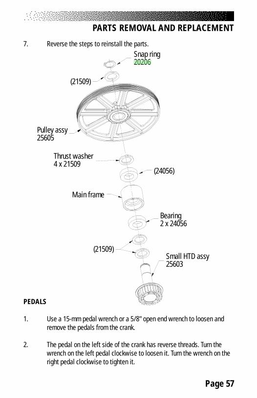
Page 57
PARTS REMOVAL AND REPLACEMENT
7. Reverse the steps to reinstall the parts.
PEDALS
1. Use a 15-mm pedal wrench or a 5/8" open end wrench to loosen andremove the pedals from the crank.
2. The pedal on the left side of the crank has reverse threads. Turn thewrench on the left pedal clockwise to loosen it. Turn the wrench on theright pedal clockwise to tighten it.
Snap ring20206
Pulley assy25605
Thrust washer4 x 21509
Main frame
Bearing2 x 24056
(24056)
(21509)Small HTD assy25603
(21509)

Page 58
PARTS REMOVAL AND REPLACEMENT
3. Apply a small amount of multi-purpose grease to the threads of thepedal spindle before reinstalling the pedals on the crank.
CRANK AND BOTTOM BRACKET ASSEMBLY
1. Remove the side covers.
2. Remove the HTD belt.
3. Remove the left pedal.
4. Loosen and remove the bottom bracket jam nut located on the leftside of the crank. This nut has reverse threads; loosen it by turning itclockwise.
5. Remove the round, metal crank shield and the spacer from the left sideof the crank.
6. The left bearing nut assembly can be removed from the crank with a15-mm cone wrench. This nut has reverse threads; loosen andremove it by turning it clockwise.
7. Slide the crank out of the frame to the right.
8. The right bearing nut assembly can be removed from the crank with a32-mm cone wrench.
9. Inspect the bearings for smoothness of operation. Replace thebearings if necessary.
10. Ensure that the right bearing nut assembly is tight against thelarge HTD pulley before reinstalling the crank into the frame. Theoutside edge of the bearing nut assembly should be flush with edge ofthe main frame (bottom bracket) when the crank is installed.
11. Install the left bearing nut assembly onto the crank and tighten it sothe outside edge of the bearing nut assembly is flush with the bottombracket. Do not overtighten the nut; the crank should spin freely.
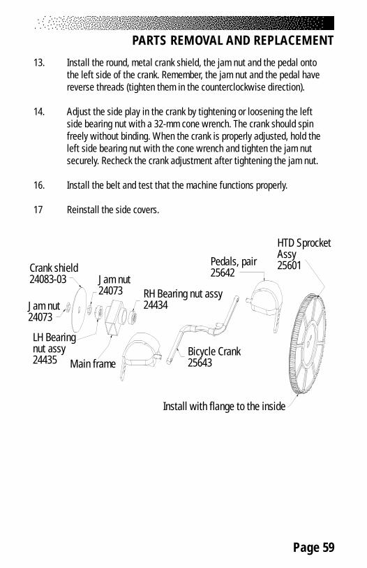
Page 59
13. Install the round, metal crank shield, the jam nut and the pedal ontothe left side of the crank. Remember, the jam nut and the pedal havereverse threads (tighten them in the counterclockwise direction).
14. Adjust the side play in the crank by tightening or loosening the leftside bearing nut with a 32-mm cone wrench. The crank should spinfreely without binding. When the crank is properly adjusted, hold theleft side bearing nut with the cone wrench and tighten the jam nutsecurely. Recheck the crank adjustment after tightening the jam nut.
16. Install the belt and test that the machine functions properly.
17 Reinstall the side covers.
PARTS REMOVAL AND REPLACEMENT
Install with flange to the inside
HTD SprocketAssy25601Pedals, pair
25642
Bicycle Crank25643
RH Bearing nut assy24434
Crank shield24083-03
Jam nut24073
LH Bearingnut assy24435 Main frame
Jam nut24073
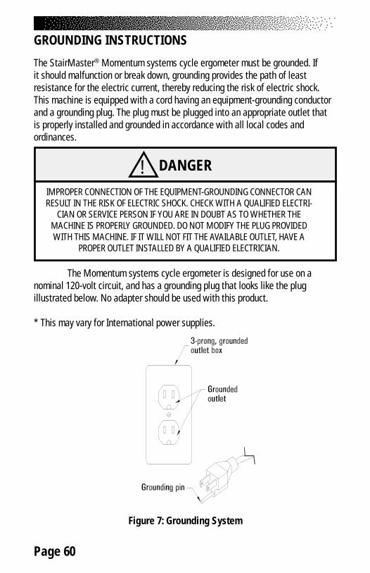
Page 60
GROUNDING INSTRUCTIONS
The StairMaster® Momentum systems cycle ergometer must be grounded. Ifit should malfunction or break down, grounding provides the path of leastresistance for the electric current, thereby reducing the risk of electric shock.This machine is equipped with a cord having an equipment-grounding conductorand a grounding plug. The plug must be plugged into an appropriate outlet thatis properly installed and grounded in accordance with all local codes andordinances.
The Momentum systems cycle ergometer is designed for use on anominal 120-volt circuit, and has a grounding plug that looks like the plugillustrated below. No adapter should be used with this product.
* This may vary for International power supplies.
Figure 7: Grounding System
! DANGER
IMPROPER CONNECTION OF THE EQUIPMENT-GROUNDING CONNECTOR CANRESULT IN THE RISK OF ELECTRIC SHOCK. CHECK WITH A QUALIFIED ELECTRI-
CIAN OR SERVICE PERSON IF YOU ARE IN DOUBT AS TO WHETHER THEMACHINE IS PROPERLY GROUNDED. DO NOT MODIFY THE PLUG PROVIDEDWITH THIS MACHINE. IF IT WILL NOT FIT THE AVAILABLE OUTLET, HAVE A
PROPER OUTLET INSTALLED BY A QUALIFIED ELECTRICIAN.
Page 61
NOTICE OF FCC COMPLIANCE
This equipment has been tested and found to comply with the limits for a Class Bdigital device, pursuant to Part 15 of the FCC rules. These limits are designed toprovide reasonable protection against harmful interference in a residentialinstallation. This equipment generates, uses and can radiate radio frequencyenergy and, if not installed and used in accordance with the instructions, maycause harmful interference to radio communications. However, there is noguarantee that interference will not occur in a particular installation. If thisequipment does cause harmful interference to radio or television reception,which can be determined by turning the equipment off and on, the user isencouraged to try to correct the interference by one or more of the followingmeasures:
• Reorient or relocate the receiving antenna.• Increase the separation between the equipment and receiver.• Connect the equipment into an outlet on a circuit different from that to
which the receiver is connected.• Consult the dealer or an experienced radio/TV technician for help.
Canadian Doc Class B Compliance
This digital apparatus does not exceed the Class B limits for radio emissions fromdigital apparatus set out in the radio interference regulations of the CanadianDepartment of Communications.
La présent appareil numérique ne dépasse pas les limites etablies pour les bruitsradioélectriques applicables aux appareils numériques de la Class B prescritesdans les règlement sur le brouillage radioélectrique édicté par le Ministère desCommunications du Canada.
! WARNINGCHANGES OR MODIFICATIONS TO EQUIPMENT NOT
EXPRESSLY APPROVED BY STAIRMASTER® HEALTH & FITNESSPRODUCTS, INC. COULD VOID THE USER'S AUTHORITY TO
OPERATE THIS EQUIPMENT.

Page 62
If you need assistance, please have both the serial number of your machine andthe date of purchase available when you contact the appropriate StairMaster®
Health & Fitness Products, Inc. office listed below.
OFFICES IN THE UNITED STATES
CORPORATE HEADQUARTERS CUSTOMER SERVICE12421 Willows Road NE, Suite 100 12421 Willows Road NE, Suite 100Kirkland, WA 98034 Kirkland, WA 98034(800) 635-2936 or (425) 823-1825 (800) 331-3578FAX: (425) 823-9490 FAX: (425) 814-0601www.stairmaster.com E-mail: customerservice@
stairmaster.com
INTERNATIONAL OFFICES AND DISTRIBUTORS
For technical assistance and a list of distributors in your area, please call or faxone of the following numbers.
INTERNATIONAL DIVISION ASIA PACIFIC HEADQUARTERS(425) 823-1825 Telephone/Fax:+81-45-590-5686FAX: (425) 820-7505 E-mail: [email protected]: [email protected]
EUROPE: HEADQUARTERS+41-91-827-3801FAX: +41-91-827-8902E-Mail: [email protected]
GERMANY: HEADQUARTERS+49-2204/610-27FAX: +49-2204/628-90E-Mail: [email protected]
U.K.: HEADQUARTERS+44-1908/267-345FAX: 44-1908/267-346E-mail: [email protected]
IMPORTANT PHONE NUMBERS

Page 63
BATTERY RECYCLING CENTERS
After installing a new battery, you will need to properly dispose of (recycle) yourold lead-acid battery. Most federal and state regulations require lead-acidbatteries be recycled. Do not throw away old batteries. Lead is a heavy metaland is toxic to living organisms. Contact the nearest Yuasa-Exide, Inc. recyclingcenter from the list below to get information on the proper disposal of your oldlead-acid battery.
STATE ADDRESS PHONE NUMBER Alabama 906 40th St. (205) 591-0606
Birmingham, AL 35222California, Northern 3470 Depot Rd. (510) 887-8080
Hayward, CA 94545California, Southern 1250 Bixby Dr. (818) 333-3060
City of Industry, CA 91745Colorado 12860 W. Cedar Dr. (303) 763-5833
Suite 106ALakewood, CO 80228
Florida 11310 Satellite Blvd. (407) 857-9234Orlando, FL 32821
Georgia 1721-C Oakbrook Dr. NE (404) 446-8663Norcross, GA 30093
Illinois 5303 Ninth Ave (708) 352-3665Countryside, IL 60525
Maryland 899 Airport Rd. Ste E (410) 768-5586Glen Burnie, MD 21061
Massachusetts 13 Wheeling Ave. (617) 932-6570Woburn, MA 01801
Michigan, Southeast 2760 Auburn Rd.Auburn Hills, MI 48326
Michigan, West 2882 Remico St. SW (616) 531-1120Grandville, MI 49418
Minnesota 1900 Oakcrest Ave. Ste 5 (612) 631-2150Roseville, MN 55113
Missouri 5328 Winner Rd. (816) 231-1414Kansas City, MO 64127 (816) 231-0685
New Hampshire 17 Clinton Dr. (603) 886-5900Hollis, NH 03049
○
○
○
○
○
○
○
○
○
○
○
○
○
○
○
○
○
○
○
○
○
○
○
○
○
○
○
○
○
○
○
○
○
○
○
○
○
○
○
○
○
○
○
○
○
○
○
○
○
○
○
○
○
○
○
○
○
○
○
○
○
○
○
○
○
○
○
○
○
○
○
○
○
○
○
○
○
○
○
○
○
○
○
○
○
○
○
○
○
○
○
○
○
○
○
○
○
○
○
○
○
○
○ ○ ○ ○ ○ ○ ○ ○ ○ ○ ○ ○ ○ ○ ○ ○ ○ ○ ○ ○ ○ ○ ○ ○ ○ ○ ○ ○ ○ ○ ○ ○ ○ ○ ○ ○ ○ ○ ○ ○ ○
○ ○ ○ ○ ○ ○ ○ ○ ○ ○ ○ ○ ○ ○ ○ ○ ○ ○ ○ ○ ○ ○ ○ ○ ○ ○ ○ ○ ○ ○ ○ ○ ○ ○ ○ ○ ○ ○ ○ ○ ○
○ ○ ○ ○ ○ ○ ○ ○ ○ ○ ○ ○ ○ ○ ○ ○ ○ ○ ○ ○ ○ ○ ○ ○ ○ ○ ○ ○ ○ ○ ○ ○ ○ ○ ○ ○ ○ ○ ○ ○ ○
○ ○ ○ ○ ○ ○ ○ ○ ○ ○ ○ ○ ○ ○ ○ ○ ○ ○ ○ ○ ○ ○ ○ ○ ○ ○ ○ ○ ○ ○ ○ ○ ○ ○ ○ ○ ○ ○ ○ ○ ○
○ ○ ○ ○ ○ ○ ○ ○ ○ ○ ○ ○ ○ ○ ○ ○ ○ ○ ○ ○ ○ ○ ○ ○ ○ ○ ○ ○ ○ ○ ○ ○ ○ ○ ○ ○ ○ ○ ○ ○ ○
○ ○ ○ ○ ○ ○ ○ ○ ○ ○ ○ ○ ○ ○ ○ ○ ○ ○ ○ ○ ○ ○ ○ ○ ○ ○ ○ ○ ○ ○ ○ ○ ○ ○ ○ ○ ○ ○ ○ ○ ○
○ ○ ○ ○ ○ ○ ○ ○ ○ ○ ○ ○ ○ ○ ○ ○ ○ ○ ○ ○ ○ ○ ○ ○ ○ ○ ○ ○ ○ ○ ○ ○ ○ ○ ○ ○ ○ ○ ○ ○ ○
○ ○ ○ ○ ○ ○ ○ ○ ○ ○ ○ ○ ○ ○ ○ ○ ○ ○ ○ ○ ○ ○ ○ ○ ○ ○ ○ ○ ○ ○ ○ ○ ○ ○ ○ ○ ○ ○ ○ ○ ○
○ ○ ○ ○ ○ ○ ○ ○ ○ ○ ○ ○ ○ ○ ○ ○ ○ ○ ○ ○ ○ ○ ○ ○ ○ ○ ○ ○ ○ ○ ○ ○ ○ ○ ○ ○ ○ ○ ○ ○ ○
○ ○ ○ ○ ○ ○ ○ ○ ○ ○ ○ ○ ○ ○ ○ ○ ○ ○ ○ ○ ○ ○ ○ ○ ○ ○ ○ ○ ○ ○ ○ ○ ○ ○ ○ ○ ○ ○ ○ ○ ○
○ ○ ○ ○ ○ ○ ○ ○ ○ ○ ○ ○ ○ ○ ○ ○ ○ ○ ○ ○ ○ ○ ○ ○ ○ ○ ○ ○ ○ ○ ○ ○ ○ ○ ○ ○ ○ ○ ○ ○ ○
○ ○ ○ ○ ○ ○ ○ ○ ○ ○ ○ ○ ○ ○ ○ ○ ○ ○ ○ ○ ○ ○ ○ ○ ○ ○ ○ ○ ○ ○ ○ ○ ○ ○ ○ ○ ○ ○ ○ ○ ○
○ ○ ○ ○ ○ ○ ○ ○ ○ ○ ○ ○ ○ ○ ○ ○ ○ ○ ○ ○ ○ ○ ○ ○ ○ ○ ○ ○ ○ ○ ○ ○ ○ ○ ○ ○ ○ ○ ○ ○ ○
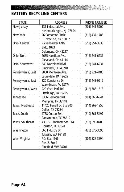
Page 64
BATTERY RECYCLING CENTERS
STATE ADDRESS PHONE NUMBERNew Jersey 131 Industrial Ave. (201) 641-5900
Hasbrouck Hgts., NJ 07604New York 26 Corporate Circle (315) 437-1788
E. Syracuse, NY 13057Ohio, Central Rickenbacker ANG (513) 851-3838
Bldg. 1073Columbus, OH 43217
Ohio, North 2635 Hamilton Ave. (216) 241-6231Cleveland, OH 44114
Ohio, Southwest 540 Northland Blvd. (216) 241-6231Cincinnati, OH 45240
Pennsylvania, East 3000 Montrose Ave. (215) 921-4480Laureldale, PA 19605
Pennsylvania, East 320 Constance Dr. (215) 443-0912Warminster, PA 18974
Pennsylvania, West 920 Vista Park Rd. (412) 788-1613Pittsburgh, PA 15205
Tennessee 3356 Democrat Rd. (901) 365-6944Memphis, TN 38118
Texas, Northeast 11420 Ferrell Dr. Ste 300 (214) 869-1855Dallas, TX 75234
Texas,South 4738 Cotton Belt (210) 661-5497San Antonio, TX 78219
Texas, Southeast 4301 S. Pinemont Ste 114 (713) 690-8700Houston, TX 77041
Washington 660 Industry Dr. (425) 575-3090Tukwila, WA 98188
West Virginia P.O. Box 1666 (304) 327-3594Rte. 2, Box 1Bluefield, WV 24701
○ ○ ○ ○ ○ ○ ○ ○ ○ ○ ○ ○ ○ ○ ○ ○ ○ ○ ○ ○ ○ ○ ○ ○ ○ ○ ○ ○ ○ ○ ○ ○ ○ ○ ○ ○ ○ ○ ○ ○ ○
○ ○ ○ ○ ○ ○ ○ ○ ○ ○ ○ ○ ○ ○ ○ ○ ○ ○ ○ ○ ○ ○ ○ ○ ○ ○ ○ ○ ○ ○ ○ ○ ○ ○ ○ ○ ○ ○ ○ ○ ○
○ ○ ○ ○ ○ ○ ○ ○ ○ ○ ○ ○ ○ ○ ○ ○ ○ ○ ○ ○ ○ ○ ○ ○ ○ ○ ○ ○ ○ ○ ○ ○ ○ ○ ○ ○ ○ ○ ○ ○ ○
○ ○ ○ ○ ○ ○ ○ ○ ○ ○ ○ ○ ○ ○ ○ ○ ○ ○ ○ ○ ○ ○ ○ ○ ○ ○ ○ ○ ○ ○ ○ ○ ○ ○ ○ ○ ○ ○ ○ ○ ○
○ ○ ○ ○ ○ ○ ○ ○ ○ ○ ○ ○ ○ ○ ○ ○ ○ ○ ○ ○ ○ ○ ○ ○ ○ ○ ○ ○ ○ ○ ○ ○ ○ ○ ○ ○ ○ ○ ○ ○ ○
○ ○ ○ ○ ○ ○ ○ ○ ○ ○ ○ ○ ○ ○ ○ ○ ○ ○ ○ ○ ○ ○ ○ ○ ○ ○ ○ ○ ○ ○ ○ ○ ○ ○ ○ ○ ○ ○ ○ ○ ○
○ ○ ○ ○ ○ ○ ○ ○ ○ ○ ○ ○ ○ ○ ○ ○ ○ ○ ○ ○ ○ ○ ○ ○ ○ ○ ○ ○ ○ ○ ○ ○ ○ ○ ○ ○ ○ ○ ○ ○ ○
○ ○ ○ ○ ○ ○ ○ ○ ○ ○ ○ ○ ○ ○ ○ ○ ○ ○ ○ ○ ○ ○ ○ ○ ○ ○ ○ ○ ○ ○ ○ ○ ○ ○ ○ ○ ○ ○ ○ ○ ○
○
○
○
○
○
○
○
○
○
○
○
○
○
○
○
○
○
○
○
○
○
○
○
○
○
○
○
○
○
○
○
○
○
○
○
○
○
○
○
○
○
○
○
○
○
○
○
○
○
○
○
○
○
○
○
○
○
○
○
○
○
○
○
○
○
○
○
○
○
○
○
○
○
○
○
○
○
○
○
○
○
○
○
○
○
○
○
○
○
○
○
○
○
○
○
○
○
○
○
○
○
○
○
○
○ ○ ○ ○ ○ ○ ○ ○ ○ ○ ○ ○ ○ ○ ○ ○ ○ ○ ○ ○ ○ ○ ○ ○ ○ ○ ○ ○ ○ ○ ○ ○ ○ ○ ○ ○ ○ ○ ○ ○ ○
○ ○ ○ ○ ○ ○ ○ ○ ○ ○ ○ ○ ○ ○ ○ ○ ○ ○ ○ ○ ○ ○ ○ ○ ○ ○ ○ ○ ○ ○ ○ ○ ○ ○ ○ ○ ○ ○ ○ ○ ○
○ ○ ○ ○ ○ ○ ○ ○ ○ ○ ○ ○ ○ ○ ○ ○ ○ ○ ○ ○ ○ ○ ○ ○ ○ ○ ○ ○ ○ ○ ○ ○ ○ ○ ○ ○ ○ ○ ○ ○ ○
○ ○ ○ ○ ○ ○ ○ ○ ○ ○ ○ ○ ○ ○ ○ ○ ○ ○ ○ ○ ○ ○ ○ ○ ○ ○ ○ ○ ○ ○ ○ ○ ○ ○ ○ ○ ○ ○ ○ ○ ○
○ ○ ○ ○ ○ ○ ○ ○ ○ ○ ○ ○ ○ ○ ○ ○ ○ ○ ○ ○ ○ ○ ○ ○ ○ ○ ○ ○ ○ ○ ○ ○ ○ ○ ○ ○ ○ ○ ○ ○ ○
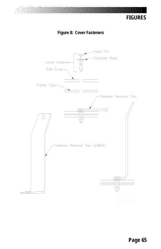
Page 65
FIGURES
Figure 8: Cover Fasteners
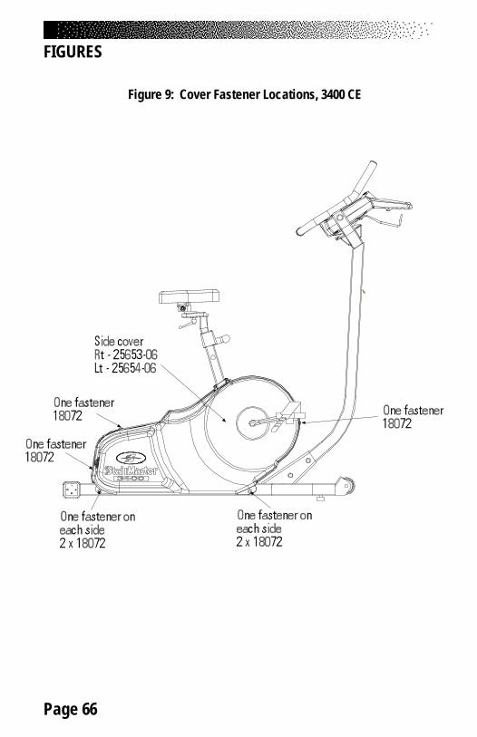
Page 66
FIGURES
Figure 9: Cover Fastener Locations, 3400 CE
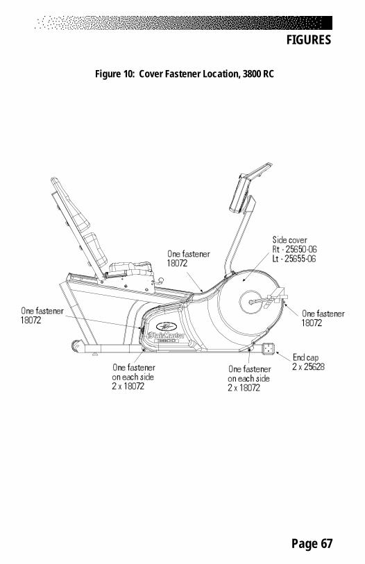
Page 67
FIGURES
Figure 10: Cover Fastener Location, 3800 RC
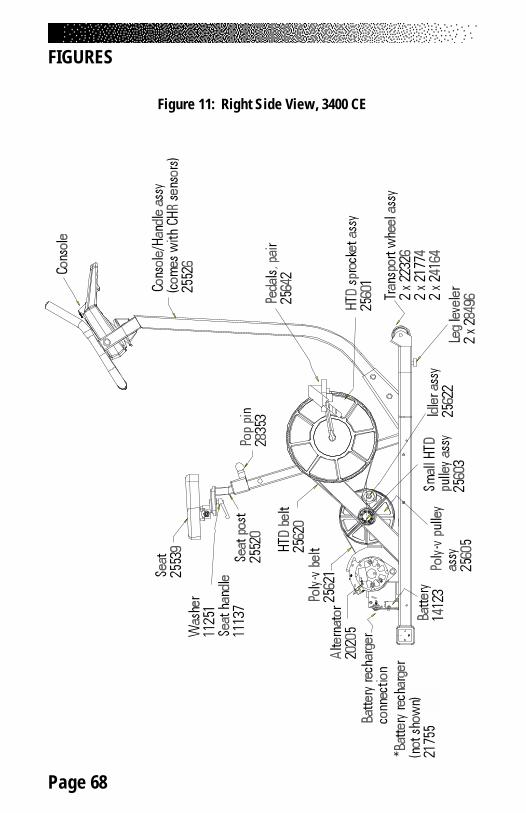
Page 68
Figure 11: Right Side View, 3400 CE
FIGURES
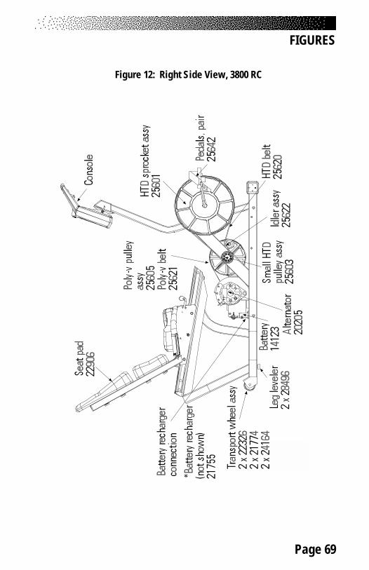
Page 69
FIGURES
Figure 12: Right Side View, 3800 RC
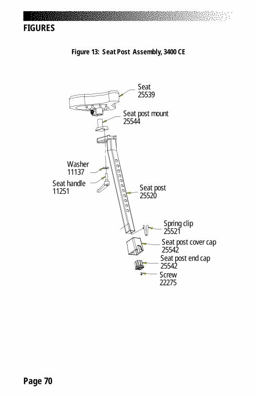
Page 70
FIGURES
Figure 13: Seat Post Assembly, 3400 CE
Seat25539
Seat post mount25544
Washer11137
Seat handle11251 Seat post
25520
Spring clip25521
Seat post cover cap25542Seat post end cap25542Screw22275

Page 71
FIGURES
Figure 14: Seat Assembly, 3800 RC
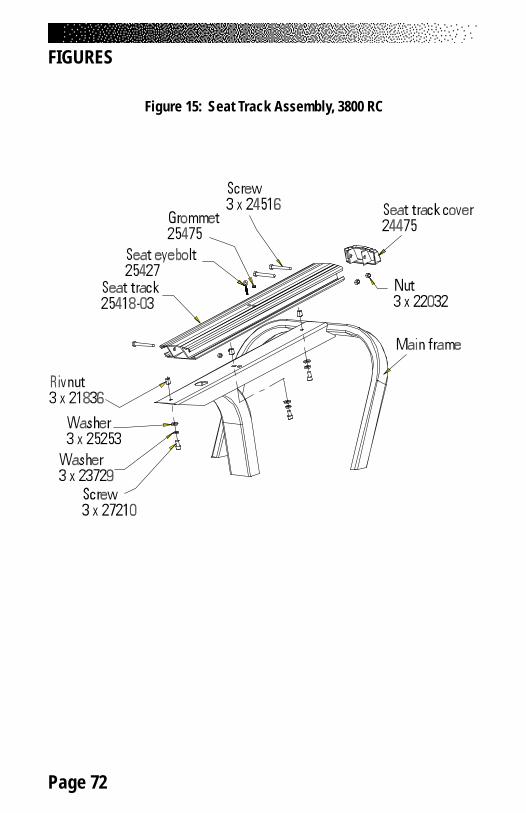
Page 72
FIGURES
Figure 15: Seat Track Assembly, 3800 RC

Page 73
FIGURES
Figure 16: Intermediate Poly-V Assembly
Snap ring20206
Pulley assy25605
Thrust washer4 x 21509
Main frame
Bearing2 x 24056
(24056)
(21509)Small HTD assy25603
(21509)
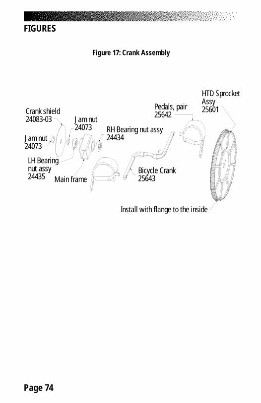
Page 74
FIGURES
Figure 17: Crank Assembly
Install with flange to the inside
HTD SprocketAssy25601Pedals, pair
25642
Bicycle Crank25643
RH Bearing nut assy24434
Crank shield24083-03
Jam nut24073
LH Bearingnut assy24435 Main frame
Jam nut24073

Page 75
FIGURES
Figure 18: Alternator/Flywheel Assembly
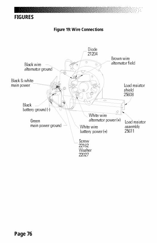
Page 76
FIGURES
Figure 19: Wire Connections
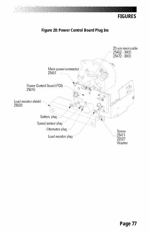
Page 77
FIGURES
Figure 20: Power Control Board Plug Ins
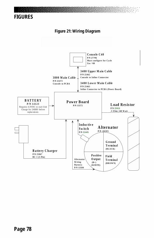
Page 78
FIGURES
Figure 21: Wiring Diagram
P ow er B oardP/N 13 57 2
B A T T E R YP /N 1 4 1 2 3
Requires 6.0VD C to s tart UnitCharge for 24HRS before
replac em ent.
B a tte ry C h a rg e rP/N 25 06 7B C - 1 (3 -Pin )
I n d u c tiv eS w itc hP/N 21 44 5
A ltern atorP /N 2 0 2 0 5
L oad R es is torP/N 25 61 1.5 O h m 2 40 W a tt
P o s itiveO utput (B + )(W HI TE)
G ro undT e rm ina l(B L A C K)
F ie ldT e rm ina l(B R O W N)
3 4 0 0 U ppe r M a in C a bleP/N 25 46 2C on s o le to I n lin e C o n n e ctor
3 4 0 0 L o w e r M a in C a bleP/N 25 46 3I n lin e C on n e ct or to PC B A ( Powe r B oa rd)
C o ns o le C 4 0P/N 27 79 6M u s t con f ig u re fo r C ycleUs e ^8 0
A lte rn a to rW irin gHarn e s sP/N 13 58 4
3 8 0 0 M a in C a bleP/N 25 47 3C on s o le to PC B A