Moment redistribution and ductility of RHSC continuous...
15
Turkish J. Eng. Env. Sci. 33 (2009) , 45 – 59. c T ¨ UB ˙ ITAK doi:10.3906/muh-0901-6 Moment redistribution and ductility of RHSC continuous beams strengthened with CFRP A. A. MAGHSOUDI 1 , H. Akbarzadeh BENGAR 2 1 Civil Engineering Department, Kerman University, Kerman-IRAN e-mail: [email protected] 2 Civil Engineering Department, Kerman University, Kerman-IRAN e-mail: h akbarzadeh [email protected] Received 12.01.2009 Abstract In continuous concrete beams, ductility allows redistribution of moment between the negative and positive moment zones. Although many in situ reinforced high strength concrete (RHSC) beams are of continuous construction, there has been very little research on such beams with external reinforcement. Due to prema- ture debonding failures and the linear stress-strain characteristics of fiber reinforced polymer (FRP) up to failure, the ductility of plated members and their ability to redistribute moment is less than that of unplated RC beams. The present study examined the responses of RHSC continuous beams, in terms of enhancement of moment and load capacity, moment redistribution, and different types of ductility. Thickness of carbon FRP (CFRP) sheets, strengthening of both the hogging and sagging region, and end anchorage technique were the main parameters investigated. Various monitoring devices were used to monitor the loading history of the beams. Increasing the number of CFRP sheet layers increased ultimate strength, and decreased ductility, moment redistribution, and ultimate strain on CFRP sheets. Additionally, using end anchorage increased ultimate strength and moment redistribution. The moment enhancement ratio of the strengthened beams was significantly higher than the ultimate load enhancement ratio in the same beam. The proposed equation for converting the energy ductility index to the displacement ductility index provided accurate results. Key Words: RHSC continuous beam; CFRP; End anchorage; Moment redistribution; Ductility. Introduction Concrete structures can become deficient during their service life and require strengthening and repair. While many methods of strengthening structures are available, strengthening structures via external bonding of ad- vanced fiber-reinforced polymer (FRP) composite has become very popular worldwide during the past decade due to the well-known advantages of FRP composites over other materials. Consequently, a great quantity of re- search, both experimental and theoretical, has been conducted on the behavior of FRP-strengthened reinforced 45
Transcript of Moment redistribution and ductility of RHSC continuous...

Turkish J. Eng. Env. Sci.33 (2009) , 45 – 59.c© TUBITAKdoi:10.3906/muh-0901-6
Moment redistribution and ductility of RHSC continuous beamsstrengthened with CFRP
A. A. MAGHSOUDI1, H. Akbarzadeh BENGAR2
1Civil Engineering Department, Kerman University, Kerman-IRANe-mail: [email protected]
2Civil Engineering Department, Kerman University, Kerman-IRANe-mail: h akbarzadeh [email protected]
Received 12.01.2009
Abstract
In continuous concrete beams, ductility allows redistribution of moment between the negative and positive
moment zones. Although many in situ reinforced high strength concrete (RHSC) beams are of continuous
construction, there has been very little research on such beams with external reinforcement. Due to prema-
ture debonding failures and the linear stress-strain characteristics of fiber reinforced polymer (FRP) up to
failure, the ductility of plated members and their ability to redistribute moment is less than that of unplated
RC beams.
The present study examined the responses of RHSC continuous beams, in terms of enhancement of
moment and load capacity, moment redistribution, and different types of ductility. Thickness of carbon
FRP (CFRP) sheets, strengthening of both the hogging and sagging region, and end anchorage technique
were the main parameters investigated.
Various monitoring devices were used to monitor the loading history of the beams. Increasing the
number of CFRP sheet layers increased ultimate strength, and decreased ductility, moment redistribution,
and ultimate strain on CFRP sheets. Additionally, using end anchorage increased ultimate strength and
moment redistribution. The moment enhancement ratio of the strengthened beams was significantly higher
than the ultimate load enhancement ratio in the same beam. The proposed equation for converting the
energy ductility index to the displacement ductility index provided accurate results.
Key Words: RHSC continuous beam; CFRP; End anchorage; Moment redistribution; Ductility.
Introduction
Concrete structures can become deficient during their service life and require strengthening and repair. Whilemany methods of strengthening structures are available, strengthening structures via external bonding of ad-vanced fiber-reinforced polymer (FRP) composite has become very popular worldwide during the past decadedue to the well-known advantages of FRP composites over other materials. Consequently, a great quantity of re-search, both experimental and theoretical, has been conducted on the behavior of FRP-strengthened reinforced
45

MAGHSOUDI, BENGAR
concrete (RC) structures, including beams, slabs, and columns (Meier et al., 1993; Teng et al., 2002). In this
regard, the evolving technology of using carbon-bonded fiber-reinforced polymers (CFRP) for strengthening
simply supported RC beams has attracted much attention in recent years. Fiber-reinforced polymer (FRP)materials in such forms as pultruded plates, fabrics, and sheets have been used as strengthening materials forRC beams. In particular, their practical implementations for flexural strengthening are numerous (Saadat-manesh and Ehsani, 1991; Arduini and Nanni, 1997; Spadea et al., 2001; Bencardino et al., 2002; Rabinovitchand Frostig, 2003; Toutanji et al., 2006; Camata, 2007; Li et al., 2008; Wang and Hsu, 2008), resulting intremendous improvement in their application.
Possible failure mechanisms observed in experimental tests were reported by Teng et al. (2002). Prematurefailures, such as delamination, and FRP and laminate separation, can significantly limit capacity enhancementand the ultimate flexural capacity of the retrofitted beams.
Several studies were conducted to identify methods of preventing premature failure with the aim of improvingthe load capacity and ductility of RC beams. Researchers studied the use of end anchorage techniques, such asU-straps, L-shape jackets, and steel clamps, for preventing premature failure of RC beams strengthened withFRP sheets (Spadea et al., 1998; Pham Al-Mahaidi, 2006; Xiong et al., 2007).
Ductility is an important factor for any structural element or structure, especially in regions of seismicactivity. Although external strengthening of RC beams with epoxy-bonded FRP has been established as aneffective tool for increasing flexural and/or shear strength, the method still suffers from some drawbacks. Manyof these drawbacks are attributed to the characteristics of currently available commercial CFRP strengtheningsystems. Although CFRPs have high strength, they are very brittle. When loaded in tension, FRPs exhibit alinear stress-strain behavior up to failure, without exhibiting a yield plateau or any indication of an impendingfailure. As FRPs behave differently than steel, they consequently suffer from a significant loss in beam ductility,particularity when CFRPs are used for flexural strengthening of RC beams (Saadatmanesh and Ehsani, 1991;
Arduini and Nanni, 1997; Spadea et al., 2001; Bencardino et al., 2002; Toutanji et al., 2006).
With recent advancements in concrete technology, and the availability of various types of mineral andchemical admixtures and very powerful superplasticizers, concrete with a compressive strength of up to 100MPa can now be produced commercially with an acceptable level of variability using ordinary aggregates.These developments have led to increased applications of high-strength concrete (HSC) all around the globe.Although HSC offers many advantages over conventional concrete, as the strength of concrete increases someof its characteristics and engineering properties become different from those of normal-strength concrete (NSC)
(ACI, 1992; Rashid et al., 2002). These differences in material properties may have important consequences in
terms of the structural behavior and design of HSC members (Oztekin et al., 2003). This concrete, with veryhigh compressive strength, can result in less ductile responses of the structural members. It has been determinedthat flexural ductility, in terms of maximum curvatures attainable, may be less in HSC beams (Rashid et al.,
2002).
HSC provides a better solution for reducing the size and weight of concrete structural elements, particularlyfor long-span beams (Ashour, 2000). HSC structures can become deficient during their service life and requirestrengthening and repair. This need may arise as a result of design or construction errors, functional changes,changes in design codes, or damage accumulated over time or caused by accidental overloading, fires, or earth-quakes. While complete replacement of a deficient/deteriorated structure is an option, strengthening/repair isoften a more economical option.
46

MAGHSOUDI, BENGAR
Although many in situ RC beams are of continuous construction, there has been very little research into thebehavior of such beams with external reinforcement (El-Refaie et al., 2003a; Ashour et al., 2004; Grace et al.,
2004). In addition, most design guidelines have been developed for simply supported beams with external FRP
laminates (FIB, 2001; JSCE, 2001; ACI, 2002). Ductility is even more important for statically indeterminatestructures, such as continuous beams, as it allows for moment redistribution through the rotation of plastichinges. Moment redistribution facilitates utilization of the full capacity of more segments of the beam.
Ashour et al. (2004) reported that all strengthened beams have increased beam load capacity, but lowerductility than their respective non-strengthened control beams, and that increasing CFRP sheet length to coverthe entire hogging or sagging zone did not prevent premature failure. Further research on the performanceof end anchorage techniques is necessary to minimize the risk of this type of failure; strengthening the topsurface at the central support and the beam soffit was reported to be the most effective configuration for CFRPlaminates for enhancing beam load capacity (El-Refaie et al., 2003a; Ashour et al., 2004).
Grace et al. (2004) investigated the effectiveness of a new triaxially braided ductile fabric in providingductility in RC continuous beams strengthened in flexure. As previously mentioned, ductility is an importantfactor in the design of HSC members under flexure; therefore, the present study examined the use of RHSCcontinuous beams strengthened with CFRP. The objective of this research was to examine the ultimate stage andductility of RHSC continuous beams in structures strengthened with CFRP sheets. The experiment included5 continuous (2-span) beams with overall dimensions equal to 250 × 150 × 6000 mm. Each beam was loadedwith a concentrated load at the middle of the span. Thickness of CFRP sheets, strengthening of both thehogging and sagging regions, and end anchorage technique were the main parameters investigated. During theexperiment, deflection and strains on concrete compressive regions, and along the CFRP sheets at the centralsupport and mid span were measured until failure. The responses of the continuous beams were examined andare discussed in terms of moment and load capacity, moment redistribution, and different types of ductility.
Experiment
Test specimens and CFRP bonding procedure
Five large-scale RC 2-span beams were tested until failure: 1 HSRC control beam and 4 HSRC beams strength-ened with externally bonded CFRP sheets on the tension face. Beam geometry and reinforcement, as well asloading and support configurations are illustrated in Figure 1. The beams were symmetrically reinforced withtwo 16-mm diameter rods at the top and bottom. To avoid shear failure, the beams were slightly over-designedfor shear, with 10-mm diameter closed stirrups spaced every 100 mm.
Thickness of CFRP laminates and end anchorage were the main parameters investigated, as summarizedin Table 1. Thickness and width of each layer of CFRP sheet were 0.11 mm and 145 mm, respectively. Thecontrol beam (CB) had no external reinforcement. The other beams were strengthened at both negative andpositive moment regions. The SC1 beam employed 1 layer of CFRP sheet, while the SC2 and SC3 beams used2 and 3 layers of CFRP sheet, respectively, with U-wrap at the ends of the laminates. The SC3N beam used3 layers of CFRP sheet, without end straps. SC3N was prepared in order to understand the effectiveness ofend anchorage on the ductility and flexural strength of RHSC continuous beams. The end anchorage system,consisting of 2 or 3 plies of CFRP sheet 150 mm wide, was wrapped and bonded around the sides and the soffitof the concrete beams near the end of the longitudinal CFRP sheets (Figure 1).
47

MAGHSOUDI, BENGAR
Electrical strain gaugeon CFRP sheet
Electrical straingauges on concrete
Load Cell Electrical strain gaugeon CFRP sheet600 mm 825 mm 1375 mm
LVDT50 mm
2850 mm3000 mm
C.L.
Electrical straingauges on concrete
C.L.
900 mm
1425 mm
P/2CFRP sheets
(a)
150 mm 145 mm
170 mm 170 mm250 mm 250 mm
150 mm145 mm
2 Φ16
2 Φ16 2 Φ16
2 Φ16
Φ10 Strirrps
200 mm
150 mm
(b) (c) (d)
Figure 1. Test set-up and monitoring devices. (a) Longitudinal profile of beam, (b) typical cross section of beam in
sagging region, (c) ) typical cross section of beam in hogging region, and (d) end anchorage system.
Table 1. Details of the test beams.
Positive momentstrengthening
Negativemoment
strengtheningBeam
no.f’c
(MPa) No. oflayersCFRPsheets
StrengthenedLength (m)
No. oflayersCFRPsheets
StrengthenedLength (m)
Endanchorage
CB 74.2 0 0 NoneSC1 74.6 1 1 NoneSC2 74.1 2 2 Yes
SC3N 75.6 3 3 NoneSC3 74.4 3
2.20
3
1.8
Yes
The process of applying the CFRP sheets to concrete involved surface preparation, priming, resin under-coating, CFRP sheet application, and resin overcoating. Prior to bonding the CFRP sheets, the beams wereground using a mechanical grinder in order to obtain a clean sound surface free of all contaminants and thencleaned with an acetone solution. After that, a 2-part primer was applied to the prepared concrete surface.Next, a 2-part epoxy resin was applied to the primed concrete surface, followed by application of the CFRPsheet. Finally, a resin overcoat was applied over the CFRP sheet. Concrete beams strengthened with CFRPsheets were cured for at least 7 days at room temperature before testing.
48
MAGHSOUDI, BENGAR
Material Properties
The HSC mix was designed by the first author and its mix proportions, with the maximum size of coarseaggregate (10 mm), are given in Table 2. For each beam six 100 × 100 × 100-mm concrete cubes were made at
the time of casting and were kept with the beams during curing. Mean concrete compressive strength (f ′c) for
each beam is shown in Table 1. The relationship between cylinder strength (f ′c) and cube strength was (f ′c=
0.85 fcu).
Two 16-mm diameter bars (Φ16) were tensile tested; the measured yield strength was 412.5 MPa and
maximum tensile strength was 626.4 MPa. The modulus of elasticity of the steel bars was 2 × 10⁵ MPa.
Young’s modulus (Efu) and ultimate tensile stress (ffu) of the CFRP sheets, and the properties of the
epoxies used for bonding the CFRP sheets were obtained from the supplier and are given in Tables 3 and 4.
Table 2. Concrete mixture proportions.
Cement(kg/m3)
Silica fume(kg/m3)
Coarse agg.(kg/m3)
Fine agg.(kg/m3)
Super lasticizer(kg/m3)
W/C ratio
650 55 723 645 11.7 0.32
Table 3. Mechanical properties of the CFRP sheets.
MaterialDensity(kg/cm3)
Thickness(mm)
UltimateTensile stressffu (MPa)
Young’sModulusEfu (GPa)
Ultimate strainεfu(%)
CFRP 1.81 0.11 3800 242 1.55
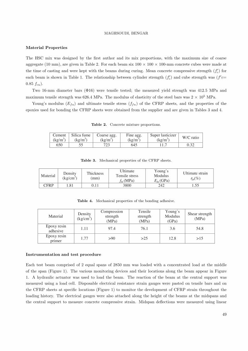
Table 4. Mechanical properties of the bonding adhesive.
MaterialDensity(kg/cm3)
Compressionstrength(MPa)
Tensilestrength(MPa)
Young’sModulus
(GPa)
Shear strength(MPa)
Epoxy resinadhesive
1.11 97.4 76.1 3.6 54.8
Epoxy resinprimer
1.77 >90 >25 12.8 >15
Instrumentation and test procedure
Each test beam comprised of 2 equal spans of 2850 mm was loaded with a concentrated load at the middleof the span (Figure 1). The various monitoring devices and their locations along the beam appear in Figure1. A hydraulic actuator was used to load the beam. The reaction of the beam at the central support wasmeasured using a load cell. Disposable electrical resistance strain gauges were pasted on tensile bars and onthe CFRP sheets at specific locations (Figure 1) to monitor the development of CFRP strain throughout theloading history. The electrical gauges were also attached along the height of the beams at the midspans andthe central support to measure concrete compressive strain. Midspan deflections were measured using linear
49
MAGHSOUDI, BENGAR
variable differential transformers (LVDTs). The load was applied step-by-step up to failure in a load-controlmanner. Strain gauge, LVDT, and the load cell readings were recorded at each load increment using datalogging equipment. At the end of each load increment, observations, measurements, crack development, andpropagation on the beam surfaces were recorded.
Test Results and Discussion
All beams were loaded with a concentrated load at the middle of the span. The obtained experimental resultsare presented and subsequently discussed in terms of the observed mode of failure, enhancement of load andmoment capacity, moment retribution, and different types of ductility.
Failure mode and ultimate strain
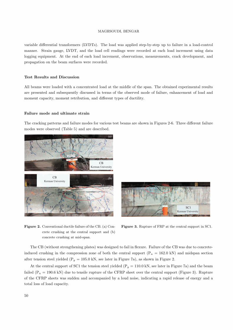
The cracking patterns and failure modes for various test beams are shown in Figures 2-6. Three different failuremodes were observed (Table 5) and are described.
��������� ������
��������� ������
���
���
���������� ������
Figure 2. Conventional ductile failure of the CB. (a) Con-
crete crushing at the central support and (b)
concrete crushing at mid-span.
Figure 3. Rupture of FRP at the central support in SC1.
The CB (without strengthening plates) was designed to fail in flexure. Failure of the CB was due to concrete-
induced crushing in the compression zone of both the central support (Pu = 162.0 kN) and midspan section
after tension steel yielded (Py = 105.0 kN, see later in Figure 7a), as shown in Figure 2.
At the central support of SC1 the tension steel yielded (Py = 110.0 kN, see later in Figure 7a) and the beam
failed (Pu = 190.6 kN) due to tensile rupture of the CFRP sheet over the central support (Figure 3). Ruptureof the CFRP sheets was sudden and accompanied by a loud noise, indicating a rapid release of energy and atotal loss of load capacity.
50

MAGHSOUDI, BENGAR
SC2Kerman University
SC2Kerman University
(b)
(a) (b)
Figure 4. Failure modes observed in SC2. (a) IC debonding at the negative moment and (b) rupture of the end strap at
the hogging region.
���
���������� ������
Figure 5. IC debonding at negative moment in SC3
beam.
Figure 6. IC debonding at the positive moment in SC3N.
0
50
100
150
200
250
0 2000 4000 6000 8000 10000
Tot
alA
pplie
dL
oad
(kN
)
Steel Strain (μ)
CB
SC1
SC2
SC3
SC3N
εy
(a)
0
50
100
150
200
250
300
0 10 20 30 40 50 60 70 80 90
Tot
alA
pplie
dL
oad
(kN
)
Mid-Span Deflection (mm)
CBSC1SC2SC3SC3N
AB
CC
A = concrete cracking pointB = steel yielding pointC = failure point
(b)
Figure 7. Total applied load versus (a) tensile steel strain at the central support and (b) midspan deflection curves of
the tested beams.
At the central support of SC2 the tension steel yielded (Py = 124.6 kN, see later in Figure 7a) and the beam
exceeded the load achieved by SC2 and failed suddenly at a load of Pu = 193.3 kN due to intermediate crack(IC) debonding at the negative moment strengthening CFRP sheet, as shown in Figure 4, followed by rupture
of the end strap at the hogging region and (IC) debonding at the positive moment strengthening CFRP sheet
(Pu = 219.3 kN).Based on experimental observation, the debonding failure can be explained as follows: due to the flexural
cracks formed in the central support as the load increased, the bond between the FRP and concrete startedto fracture at a certain load level and the failure propagated towards the mid-span until most of the FRPcomposites detached from the concrete beams. It can be seen that the bond between the FRP and concretewas not strong enough to ensure the rupture of the composites with more than 1 layer of carbon fiber sheets;thus, the FRP-concrete bond strength controlled the failure mode when more than 1 layer of fiber sheets werebonded. When 1 layer of carbon fiber is applied, the bond problem is not a factor controlling failure; thus, theforce in the FRP will reach its ultimate tensile capacity when the beam fails.
51

MAGHSOUDI, BENGAR
Table 5. Beam test results, including ultimate and yielding of load, and deflection and ultimate strain of CFRP.
Compressiveconcrete ltimate
strain(micron)
Ultimatestrain ofCFRP
(micron)Beam
Failure modPy
(kN)ξ Pu
(kN)λ
Centralsupport
MidspanCentralsupport
Midspan
CBFlexuralfailure
105 1 162 1 4400 4600 - -
SC1
Rupture of topCFRP sheetat hogging
region110 1.05 190.6 1.18 1800 2500 10000 10618
SC2
IC debondingat hogging
regionfollowed by
rupture of endstrap athoggingregion
124.6 1.18 219.3 1.35 2700 2800 7030 7785
SC3
IC debondingat hogging
region136 1.29 259.3 1.6 2600 2600 8922 7000
SC3NIC debonding
at saggingregion
138.6 1.32 236 1.45 2100 1900 6704 7268
no. e
u
At the central support of SC3 the tension steel yielded (Py= 136.0 kN, see later in Figure 7a) and the beam
failed via IC debonding at the negative moment (Figure 5). End straps did not rupture because 3 layers ofU-wrap were used.
At the central support of SC3N the tension steel yielded (Py= 138.6 kN, see later in Figure 7a) and the
beam failed (Pu= 236.0 kN) via IC debonding at the positive moment (Figure 6).
For the tested beams concrete was not initially pre-cracked and the development of the cracks during thetest was greatly influenced by the number of CFRP layers. The occurrence of the first crack was delayed andmore diffuse. Shear cracks occurred in the beams for an applied load of about 70% of the ultimate load. Figures3-6 also indicate that the strengthened beams had many diagonal cracks, which were caused by the increase inflexural capacity due to the CFRP sheets.
The maximum recorded strain values for the CFRP sheets and compressive concrete at the central supportand mid span before beam failure load are given in Table 5. It can be seen that increasing the number ofCFRP layers in strengthened beams reduced the tensile ultimate strain of the CFRP sheets. Moreover, use ofend anchorage in the strengthened beams increased the failure strain of CFRP sheets. Strengthening beamssignificantly reduced the ultimate concrete compressive strain.
52

MAGHSOUDI, BENGAR
Load-Deflection and Enhancement of Failure Load
The total applied load versus tensile steel strain at the central support and deflection diagrams at mid-spanof tested beams are shown in Figure 7. Figure 7b indicates that each strengthened continuous beam curveexhibited almost 3 straight lines with slightly different responses up to failure, representing the concrete pre-cracking (OA), concrete post-cracking tension steel pre-yield (AB), and tension steel post-yield stages (BC).Yet, the CB showed almost 2 straight lines of pre-cracking and post-cracking behavior, with a yield plateau inthe post-yield stage.
Behavior of the beams was very similar in the uncracked elastic stage. In other words, the beams’ flexuralstiffness was the same until the occurrence of cracks in the concrete. In the cracked pre-yield stage (Figure 7b)the stiffness of the strengthened beams was slightly higher than that of the CB; however, significant decreasesin beam stiffness were observed after yielding of tensile steel at the negative and positive moment sections,whereas by increasing the number of CFRP layers the loss of beam stiffness was reduced. Increasing thenumber of CFRP layers decreased midspan deflection and generally increased stiffness for the same value ofapplied load. Comparing SC3 and SC3N, it was observed that using end anchorage can slightly increase beamstiffness after yielding of tensile steel.
Table 5 summarizes the ultimate failure load, Pu (the sum of the 2 mid-span point loads at failure), ultimate
load enhancement ratio (λ), which is the ratio of the ultimate load of an externally strengthened beam to the
CB, yielding load of tension steel at the central support (Py), and yielding load enhancement ratio (ξ), which
is the ratio of the yielding load of the strengthened beam to that of the CB. As indicated in Table 5, additionof 1, 2, and 3 layers of CFRP sheet increased the ultimate load capacity by 18%, 35%, 60%, and 45% for SC1,SC2, SC3, and SC3N, respectively, in comparison to the CB. Use of end straps led to increased load capacity ofthe strengthened beam, based on comparison of the results for SC3 and SC3N. Additionally, by increasing thenumber of CFRP layers, the yielding load of tension steel increased slightly at the central support. The use ofend straps did not increase the yielding load.
Enhancement of moment capacity and moment redistribution
Table 6 presents the failure moments and the ultimate moment enhancement ratio (χ, which is the ratio of
the ultimate moment of strengthened sections (central support and midspan sections) to that of the non-strengthened sections. Beam bending moment was calculated from the equilibrium considerations, using themeasured central support reaction and mid-span applied load. The results shown in Table 6 indicate that theaddition of 1, 2, and 3 layers of CFRP sheet increased the ultimate moment capacity at the central supportby 28%, 55%, 88%, and 73%, and at midspan by 12%, 26%, 47%, and 33%, for SC1, SC2, SC3, and SC3N,respectively, as compared to the CB. It was possible to increase the moment capacity of the strengthened beamsat the hogging and sagging regions by using end U-straps (see the results of SC3 and SC3N). In general, allthe strengthened sections resisted a higher moment than the corresponding unstrengthened sections of the CB.Comparing the ultimate load enhancement ratio of a strengthened beam and the moment enhancement ratioof a strengthened section at the central support of the same beam, it can be concluded that the latter wassignificantly higher than the former (a similar conclusion was reported by Ashour et al. (2004) and El-Refaie et
al. (2003)); however, this is not the case for simply supported beams strengthened with external reinforcement
for which the moment and load enhancement ratios are always the same (Hashemi et al., 2008).
53
MAGHSOUDI, BENGAR
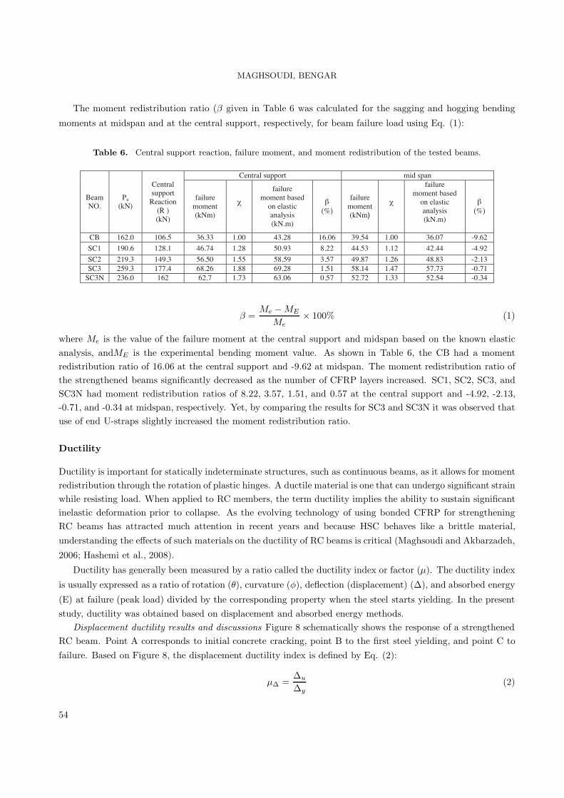
The moment redistribution ratio (β given in Table 6 was calculated for the sagging and hogging bending
moments at midspan and at the central support, respectively, for beam failure load using Eq. (1):
Table 6. Central support reaction, failure moment, and moment redistribution of the tested beams.
Central support mid span
BeamNO.
Pu
(kN)
Centralsupport
Reaction(R )(kN)
failuremoment(kNm)
χ
failuremoment based
on elasticanalysis(kN.m)
β(%)
failuremoment(kNm)
χ
failuremoment based
on elasticanalysis(kN.m)
β(%)
CB 162.0 106.5 36.33 1.00 43.28 16.06 39.54 1.00 36.07 -9.62
SC1 190.6 128.1 46.74 1.28 50.93 8.22 44.53 1.12 42.44 -4.92
SC2 219.3 149.3 56.50 1.55 58.59 3.57 49.87 1.26 48.83 -2.13SC3 259.3 177.4 68.26 1.88 69.28 1.51 58.14 1.47 57.73 -0.71
SC3N 236.0 162 62.7 1.73 63.06 0.57 52.72 1.33 52.54 -0.34
β =Me − ME
Me× 100% (1)
where Me is the value of the failure moment at the central support and midspan based on the known elasticanalysis, andME is the experimental bending moment value. As shown in Table 6, the CB had a momentredistribution ratio of 16.06 at the central support and -9.62 at midspan. The moment redistribution ratio ofthe strengthened beams significantly decreased as the number of CFRP layers increased. SC1, SC2, SC3, andSC3N had moment redistribution ratios of 8.22, 3.57, 1.51, and 0.57 at the central support and -4.92, -2.13,-0.71, and -0.34 at midspan, respectively. Yet, by comparing the results for SC3 and SC3N it was observed thatuse of end U-straps slightly increased the moment redistribution ratio.
Ductility
Ductility is important for statically indeterminate structures, such as continuous beams, as it allows for momentredistribution through the rotation of plastic hinges. A ductile material is one that can undergo significant strainwhile resisting load. When applied to RC members, the term ductility implies the ability to sustain significantinelastic deformation prior to collapse. As the evolving technology of using bonded CFRP for strengtheningRC beams has attracted much attention in recent years and because HSC behaves like a brittle material,understanding the effects of such materials on the ductility of RC beams is critical (Maghsoudi and Akbarzadeh,
2006; Hashemi et al., 2008).
Ductility has generally been measured by a ratio called the ductility index or factor (μ). The ductility index
is usually expressed as a ratio of rotation (θ), curvature (φ), deflection (displacement) (Δ), and absorbed energy
(E) at failure (peak load) divided by the corresponding property when the steel starts yielding. In the presentstudy, ductility was obtained based on displacement and absorbed energy methods.
Displacement ductility results and discussions Figure 8 schematically shows the response of a strengthenedRC beam. Point A corresponds to initial concrete cracking, point B to the first steel yielding, and point C tofailure. Based on Figure 8, the displacement ductility index is defined by Eq. (2):
μΔ =Δu
Δy(2)
54

MAGHSOUDI, BENGAR
where Δu is the midspan deflection at ultimate beam load and Δy is the midspan deflection at yielding load of
the tensile steel reinforcement at the central support.
����� �����
�
��
������������� �������������
����
Δ� Δ� Δ� Δ�
Figure 8. Definition of displacement and energy ductility (Thomsen et al., 2004).
Table 7 shows the experimental values of (Δu), (Δy), the displacement ductility index value of (μΔ), andpercentage of decrease of displacement ductility in the CB. It can be seen that increasing the number of CFRPsheet layers led to decreased mid span deflection at ultimate load, while the midspan deflection at yielding loadwas almost constant. Therefore, increasing the number of CFRP sheet layers decreased the beam displacementductility index.
Table 7. Comparison of displacement and absorbed energy of the tested beams.
Beamno.
(Δu)(mm)
(Δy)(mm)
(μΔ )byEq.(2)
Decreaseover
controlbeam(%)
(Ey)(kN.mm)
(EU)(kN.mm)
(μE)byEq.(3)
Decreaseover
controlbeam(%)
(μEp) by
4)
CB 7.5 77.4 10.32 ---- 415.2 10720 25.82 ---- 10.26SC1 7.5 26 3.47 66.4 496 3499 7.05 72.7 3.32SC2 8 23 2.87 72.2 539.24 3253.8 6.03 76.6 2.94SC3 8.9 19.88 2.23 78.4 723.17 2958.6 4.09 84.1 2.22
SC3N 8 19 2.37 77.0 602 2733 4.53 82.4 2.38
Beamno.
(Δu)(mm)
(Δy)(mm)
(μΔ )byEq.(2)
Decreaseover
controlbeam(%)
(Ey)(kN.mm)
(EU)(kN.mm)
(μE)byEq.(3)
Decreaseover
controlbeam(%)
(μEp) by
Eq. 4)
CB 7.5 77.4 10.32 ---- 415.2 10720 25.82 ---- 10.26SC1 7.5 26 3.47 66.4 496 3499 7.05 72.7 3.32SC2 8 23 2.87 72.2 539.24 3253.8 6.03 76.6 2.94SC3 8.9 19.88 2.23 78.4 723.17 2958.6 4.09 84.1 2.22
SC3N 8 19 2.37 77.0 602 2733 4.53 82.4 2.38
Beamno.
(Δu)(mm)
(Δy)(mm)
(μΔ )byEq.(2)
Decreaseover
controlbeam(%)
(Ey)(kN.mm)
(EU)(kN.mm)
(μE)byEq.(3)
Decreaseover
controlbeam(%)
(μEp) by
(4)
CB 7.5 77.4 10.32 ---- 415.2 10720 25.82 ---- 10.26SC1 7.5 26 3.47 66.4 496 3499 7.05 72.7 3.32SC2 8 23 2.87 72.2 539.24 3253.8 6.03 76.6 2.94SC3 8.9 19.88 2.23 78.4 723.17 2958.6 4.09 84.1 2.22
SC3N 8 19 2.37 77.0 602 2733 4.53 82.4 2.38
Figure 9 illustrates the effect of the quantity of CFRP on displacement ductility of RHSC continuous beams.For HSC members, a displacement ductility index (μΔ in the range of 3-5 is considered imperative for adequate
ductility, especially in areas of seismic design and the redistribution of moments (Ashour, 2000; Maghsoudi
and Akbarzadeh, 2006). Therefore, assuming that an index value of 3 represents the minimum for ensuringthe ductile behavior of RHSC continuous beams strengthened with CFRP sheet, it appears that the testedbeams (SC2, SC3, and SC3N) with a CFRP sheet ratio (Af/(b × h)) greater than 0.051 would not meet that
requirement (Af is the FRP cross-sectional area, and b and h are width and height of beams, respectively).
Energy-based method of ductility results and discussion Another method of determining ductility is basedon the energy definition; Thomsen et al. (2004) suggested an energy-based definition of ductility, which is
illustrated in Figure 8. The energy ductility index (μE) is defined as the ratio between the energy of the system
at failure (Eu) and the energy of the system at yielding load of tensile steel reinforcement at the central support
(Ey):
μE =Eu
Ey(3)
The failure energy at beam ultimate load (Eu), elastic energy at first steel yield load (Ey), the energy ductility
index (μE), and percentage of decrease of energy ductility of the CB is given in Table 7. Similar to the
55

MAGHSOUDI, BENGAR
displacement ductility index, increasing the number of CFRP sheet layers led to a decrease in the absorbedenergy at failure load; consequently, the energy ductility index of strengthened beams decreased by 72.7%,76.6%, 84.1%, and 82.4% for SC1, SC2, SC3, and SC3N, respectively, based on Eq. (3).
!
"
#
$
�
�!
% "!& % $& %�!'&
���������
���
��������
�μΔ�
��� (��)* �)� �+�
Figure 9. Effect of CFRP on displacement ductility.
Reinforced concrete structures usually behave in a ductile manner if an appropriate amount of steel rein-forcement is added. Ductility is achieved by inelastic deformation of the steel before failure. During this perioda concrete beam consumes much of the energy, causing the elastic energy released at failure to be reduced;however, the circumstance is not the same for RC beams strengthened with CFRP, because this material usu-ally cannot attain inelastic deformation. This causes a tremendous amount of elastic strain energy to build up,which exceeds that of steel reinforcement, and can be released at failure.
As seen in Table 7, a comparison between energy and the displacement ductility ratio shows that for all thebeams tested the energy ductility index value was about 2-fold higher than the displacement ductility index;however, while considering the energy ductility index (μE)we observed that none of the index values representedan acceptable minimum energy ductility value for ensuring the ductile behavior of RHSC continuous beamsstrengthened with CFRP sheets. As such, for assimilating the amount of displacement and energy ductilityit is possible to use the minimum value of the displacement ductility index (3) for the energy ductility index.Therefore, a new energy ductility index equation was proposed for assimilating the amount of displacement andenergy ductility. The quantity of the proposed energy ductility index (μEp) is assumed by Eq. (4) and Table 7
lists the obtained values for the beams we tested. It is clear that the μEp values are very close to the μΔ values.
μEp = 0.37Eu
Ey+ 0.71 (4)
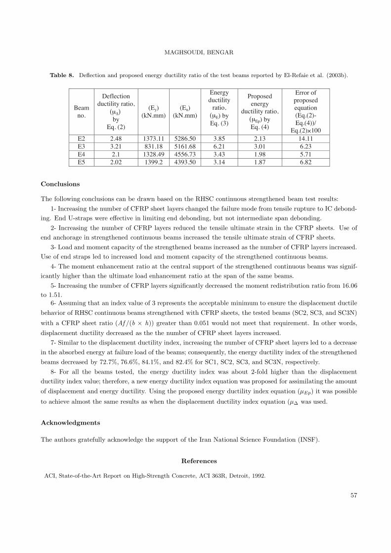
To assess further the accuracy of the proposed Eq. (4), the only available study on the energy ductility of RCcontinuous beams strengthened by CFRP was also considered, and the energy ductility index values for thetest beams reported therein were calculated and are presented in Table 8 (El-Refaie et al., 2003b). The resultslisted in Table 8 demonstrate that, except for E2, the percentage of error obtained by the proposed equationfor calculating the energy ductility of the test beams was less than 10%; therefore, the accuracy of the proposedequation is high.
56
MAGHSOUDI, BENGAR
Table 8. Deflection and proposed energy ductility ratio of the test beams reported by El-Refaie et al. (2003b).
Beamno.
Deflectionductility ratio,
(μΔ) by
Eq. (2)
(Ey)(kN.mm)
(Eu)(kN.mm)
Energyductility
ratio,(μE) byEq. (3)
Proposedenergy
ductility ratio,(μEp) byEq. (4)
Error ofproposedequation(Eq.(2)-Eq.(4))/
Eq.(2) 100E2 2.48 1373.11 5286.50 3.85 2.13 14.11E3 3.21 831.18 5161.68 6.21 3.01 6.23E4 2.1 1328.49 4556.73 3.43 1.98 5.71E5 2.02 1399.2 4393.50 3.14 1.87 6.82
Conclusions
The following conclusions can be drawn based on the RHSC continuous strengthened beam test results:1- Increasing the number of CFRP sheet layers changed the failure mode from tensile rupture to IC debond-
ing. End U-straps were effective in limiting end debonding, but not intermediate span debonding.2- Increasing the number of CFRP layers reduced the tensile ultimate strain in the CFRP sheets. Use of
end anchorage in strengthened continuous beams increased the tensile ultimate strain of CFRP sheets.3- Load and moment capacity of the strengthened beams increased as the number of CFRP layers increased.
Use of end straps led to increased load and moment capacity of the strengthened continuous beams.4- The moment enhancement ratio at the central support of the strengthened continuous beams was signif-
icantly higher than the ultimate load enhancement ratio at the span of the same beams.5- Increasing the number of CFRP layers significantly decreased the moment redistribution ratio from 16.06
to 1.51.6- Assuming that an index value of 3 represents the acceptable minimum to ensure the displacement ductile
behavior of RHSC continuous beams strengthened with CFRP sheets, the tested beams (SC2, SC3, and SC3N)
with a CFRP sheet ratio (Af /(b × h)) greater than 0.051 would not meet that requirement. In other words,displacement ductility decreased as the the number of CFRP sheet layers increased.
7- Similar to the displacement ductility index, increasing the number of CFRP sheet layers led to a decreasein the absorbed energy at failure load of the beams; consequently, the energy ductility index of the strengthenedbeams decreased by 72.7%, 76.6%, 84.1%, and 82.4% for SC1, SC2, SC3, and SC3N, respectively.
8- For all the beams tested, the energy ductility index was about 2-fold higher than the displacementductility index value; therefore, a new energy ductility index equation was proposed for assimilating the amountof displacement and energy ductility. Using the proposed energy ductility index equation (μEp) it was possible
to achieve almost the same results as when the displacement ductility index equation (μΔ was used.
Acknowledgments
The authors gratefully acknowledge the support of the Iran National Science Foundation (INSF).
References
ACI, State-of-the-Art Report on High-Strength Concrete, ACI 363R, Detroit, 1992.
57

MAGHSOUDI, BENGAR
ACI, Guide for the Design and Construction of Externally Bonded FRP Systems for Strengthening Concrete Structures”,
Farmington Hills. Mich.: American Concrete Institute, ACI 440.2R-02, 2002.
Arduini, M. and Nanni, A., “Behaviour of Precracked RC Beams Strengthened with Carbon FRP Sheets”, ASCE
Journal of Composites for Construction, 1(2), 63-70, 1997.
Ashour, S.A. “Effect of compressive strength and tensile reinforcement ratio on flexural behavior of high-strength
concrete beams”, Engineering Structures 22, 413-423, 2000.
Ashour, A.F., El-Refaie, S.A. and Garrity, S.W., “Flexural Strengthening of RC Continuous Beams using CFRP
Laminates”, Cement & Concrete Composits, 26, 765-775, 2004.
Bencardino, F., Spadea, G. and Swamy, N., “Strength and Ductility of Reinforced Concrete Beams Externally Rein-
forced with Carbon Fiber Fabric.” ACI Structural Journal, 99, 163-171, 2002.
Camata, G., Spacone, E. and Zarnic, R., “Experimental and Nonlinear Finite Element Studies of RC Beams Strength-
ened with FRP Plates”, Composites: Part B, 38, 277-288, 2007.
El-Refaie, S.A., Ashour, A.F. and Garrity, S.W., “Sagging and Hogging Strengthening of Continuous Reinforced Con-
crete Beams using Carbon Fiber-reinforced Polymer Sheets”, ACI Structural Journal, 100, 446-453, 2003a.
El-Refaie, S.A., Ashour A.F. and Garrity, S.W. “CFRP Strengthened Continuous Concrete Beams”, Structures &
Buildings, 156, Issue SB4, 395-404, 2003b.
FIB, “Externally Bonded FRP Reinforcement for RC Structures, Fe’de’ration Internacionale du beton, Task Group 9.3
FRP, 2001.
Grace, N.F., Ragheb, W.F. and Abdel-Sayed, G., “Strengthening of Cantilever and Continuous Beams using New
Triaxially Braided Ductile Fabric.” ACI Structural Journal, 101, 237-244, 2004.
Hashemi, H., Maghsoudi, A.A. and Rahgozar, R., “Flexural Ductility of Reinforced HSC Beams Strengthened with
CFRP Sheets” Structural Engineering and Mechanic, 2008, (in press).
JSCE, Recommendations for the Upgrading of Concrete Structures with Use of Continuous Fiber Sheets”, Tokyo:
Japanese Society of Civil Engineers, Concrete engineering, Series 41, 2001.
Li, L., Guo, Y. and Liu, F., “Test Analysis for FRC Beams Strengthened with Externally Bonded FRP Sheets.”
Construction and Building Materials, 22, 315-323, 2008.
Maghsoudi, A.A. and Akbarzadeh, H., “Flexural Ductility of HSC Members”, Structural Engineering and Mechanics,
24 (2), 2006.
Meier, U., Deuring, M., Meier, H. and Schwegler, G., Strengthening of Structures with Advanced Composites. Al-
ternative materials for reinforcement and prestressing of concrete, Clarke/Chapman & Hall. Glasgow, Scotland: J.L.,
1993.
Oztekin, E., Pul, S. and Husem, M., “Determination of Rectangular Stress Block Parameters for High Performance
Concrete”, Engineering Structures, 25, 371-376, 2003.
Pham, H. and Al-Mahaidi, R., “Prediction Models for Debonding Failure Loads of Carbon Fiber Reinforced Polymer
Retrofitted Reinforced Concrete Beams”, ASCE Journal of Composites for Construction, 10, 48-59, 2006.
Rabinovitch, O. and Frostig, Y., “Experiments and Analytical Comparison of RC Beams Strengthened with CFRP
Composites”, Composites: Part B, 34, 663-677, 2003.
Rashid, M.A., Mansur, M.A. and Paramasivam, P., “Correlations Between Mechanical Properties of High-Strength
Concrete”, Journal of Materials in Civil Engineering, 14, 230-238, 2002.
Saadatmanesh, H. and Ehsani, M., “RC beams Strengthened with GFRP Plates. I: Experimental study”, ASCE Journal
of Structural Engineering, 117, 3417-3433, 1991.
58

MAGHSOUDI, BENGAR
Spadea, G., Bencardino, F. and Swamy, R.N., “Structural Behaviour of Composite RC Beams with Externally Bonded
CFRP”, Journal of Composites for Construction, 2, 132-137, 1998.
Spadea, G., Swamy, R.N. and Bencardino, F., “Strength and Ductility of RC Beams Repaired with Bonded CFRP
Laminates”, Journal of Bridge Engineering, 6, 349-55, 2001.
Teng, J.G., Chen, J.F., Smith, S.T. and Lam, L., FRP Strengthened RC Structures, Wiley. New York, 2002.
Thomsen, H.H., Spacone, E., Limkatanyu, S. and Camata, G. “Failure Mode Analysis of Reinforced Concrete Beams
Strengthened in Flexure with Externally Bonded Fibre- Reinforced Polymers”, Journal of Composites for Construction,
8, 123-131, 2004.
Toutanji, H., Zhao, L. and Zhang, Y., “Flexural Behaviour of Reinforced Concrete Beams Externally Strengthened
with CFRP Sheets Bonded with an Inorganic Matrix”, Engineering Structures, 28, 557-566, 2006.
Wang, Y.C. and Hsu, K., “Design Recommendations for the Strengthening of Reinforced Concrete Beams with Exter-
nally Bonded Composite Plates.” Composite Structures, 2008, (in press).
Xiong, G.J., Jiang, X., Liu, J.W. and Chen, L., “A Way for Preventing Tension Delamination of Concrete Cover in
Midspan of FRP Strengthened Beams”, Construction and Building Materials, 21, 402-408, 2007.
59