Moment-of-uid interface reconstructionshashkov/papers/main.pdf · Interface tracking methods use...
33
Moment-of-fluid interface reconstruction Vadim Dyadechko *† Mikhail Shashkov † LA-UR-05-7571 Abstract We designed a new volume-conservative interface reconstruction method. An input data set for the interface reconstruction algorithm consists of volumes and centroids of the cell fractions occupied by different materials. Compared to pure volume fractions, traditionally used by volume-of-fluid (VoF) methods, this choice of the input data allows to define a linear interface approximation per mixed cell (i.e. offers Piecewise-Linear Interface Calculation or Construc- tion (PLIC)) even without exchanging information between neighboring elements. The location of linear interface in each mixed cell is chosen to preserve the vol- umes and provide the best approximation to the centroids of the cell fractions. The technique proposed yields a second order accurate approximation to inter- faces given by simple C 2 curves and is shown to be more accurate than known VoF-PLIC methods. 1 Introduction There is a variety of discrete interface models developed for Eulerian simulations of a multi-phase fluid flow: • Level sets methods [19, 18, 13, 20, 7] work with implicit representation of the interface as a zero level set of a discrete signed distance function defined for each pair of adjacent fluid phases. * corresponding author; e-mail: [email protected] † Mathematical Modeling and Analysis Group (T-7) at Los Alamos National Laboratory 1
Transcript of Moment-of-uid interface reconstructionshashkov/papers/main.pdf · Interface tracking methods use...

Moment-of-fluid interface reconstructionVadim Dyadechko∗† Mikhail Shashkov†
LA-UR-05-7571
Abstract
We designed a new volume-conservative interface reconstruction method.An input data set for the interface reconstruction algorithm consists of volumesand centroids of the cell fractions occupied by different materials. Comparedto pure volume fractions, traditionally used by volume-of-fluid (VoF) methods,this choice of the input data allows to define a linear interface approximationper mixed cell (i.e. offers Piecewise-Linear Interface Calculation or Construc-tion (PLIC)) even without exchanging information between neighboring elements.The location of linear interface in each mixed cell is chosen to preserve the vol-umes and provide the best approximation to the centroids of the cell fractions.The technique proposed yields a second order accurate approximation to inter-faces given by simple C2 curves and is shown to be more accurate than knownVoF-PLIC methods.
1 IntroductionThere is a variety of discrete interface models developed for Eulerian simulationsof a multi-phase fluid flow:
• Level sets methods [19, 18, 13, 20, 7] work with implicit representation of theinterface as a zero level set of a discrete signed distance function defined foreach pair of adjacent fluid phases.
∗corresponding author; e-mail: [email protected]†Mathematical Modeling and Analysis Group (T-7) at Los Alamos National Laboratory
1

• Interface tracking methods use supplementary Lagrangian surface grid thatmarks the interface between different phases.
• The strategy behind interface reconstruction methods is to calculate the in-terface location at each discrete moment of time from the solution data.Two major groups of interface reconstruction methods should be mentionedhere: volume-of-fluid (VoF) [4] methods, which construct the interface fromthe volumes of the cell fractions occupied by different fluid phases, and La-grangian particle methods [22, 7, 9], which separate the clouds of test parti-cles of different origin.
Either approach has its virtues and drawbacks. The resolution of level set andVoF methods is limited by the resolution of the grid, while interface tracking andparticle methods do not have this limitation. Pure particle methods are time con-suming and are mostly used in combination with some other major techniques.Interface tracking is inexpensive and straightforward until it comes to interfacetopology modification, which is a challenging task for tracking algorithms. Levelset and interface reconstruction methods, on the contrary, naturally adopt topo-logical changes of the interface.
Among all the techniques above, VoF is the only one that preserves the massof each component. For a wide range of applications the importance of massconservation on a discrete level outbalances all the disadvantages associated withVoF methods.
The basic object of VoF methods is a two-phase medium. Volume fractionsof two components sharing a mixed cell are not independent but complementeach other to 1. Essentially only the volume fractions a of single phase, furtherreferred to as a reference one, explicitly participate in the interface reconstruction.
The most common interface representation used by VoF methods consists of asingle linear interface per mixed cell (so called Piecewise-Linear Interface Calcu-lation or Construction - PLIC). The location of linear interface for a given volumeof the reference fraction is uniquely identified by direction of the interface out-ward (with respect to the reference component) normal. There exists a numberof ways to define the normal:
• by estimating the gradient of the discrete volume fraction function [23, 24, 2];• by finding a common linear interface for a cluster of surrounding cells that
gives the best approximation to the given volume fractions [14];• by averaging the normals of linear interfaces that satisfy volume fractions
of adjacent mixed cells [6, 8, 21].Direct methods based on estimation of the volume fraction function gradient(Youngs [23, 24], Green-Gauss, and Least Square Gradient (LSG) algorithms [2])
2

LSG LVIRA Swartz MoF = original
Figure 1. Interface approximations obtained with different PLIC algorithms.MoF method is able to reproduce the original shape exactly.
are known to be first order accurate. The iterative techniques, like Least square Vol-ume Interface Reconstruction Algorithm (LVIRA) [14] and Mosso-Swartz method[21], are able to approximate C2 interfaces with second order accuracy. In ei-ther case evaluation of the interface outward normal from the volume fractionsrequires data from the surrounding cells. This inherent feature of VoF methodsprohibits the resulting approximation to resolve any interface details smaller thana characteristic size of the cell cluster involved in evaluation of the normal (seeFigure 1 on how the quality of LSG, LVIRA, or Swartz interface reconstructiondepends on the scale of details in original shape).
In order to overcome this limitation of VoF methods we propose to enrichinput data set with centroids of the cell fractions. The amount of information carriedby the volumes and centroids or, equivalently, by the first two moments of thecell fractions is sufficient to define mass-conservative PLIC approximation evenwithout exchanging data between the cells. The location of linear interface in eachmixed cell is chosen to preserve the volumes and provide the best approximation to thecentroids of the cell fractions. We call this strategy moment-of-fluid (MoF) interfacereconstruction.
With no data from adjacent cells participating in evaluation of the interface,the method is able to resolve interface details as small as the cell itself, i.e. twoto three times smaller than conventional VoF-PLIC methods (see Figure 1). Nodata exchange also means that the grid structure is irrelevant for MoF interface re-construction. Second order accurate approximation provided by MoF algorithmguarantees that, once the original interface in a mixed cell is linear, it will bereconstructed exactly (Figure 1, MoF).
Compared to alternative approaches, which exploit purely geometrical prin-ciples, centroid data involvement has a clear mechanical reason. Each instance ofinexact interface reconstruction introduces some redistribution of the fluid insidea mixed cell. This fluid motion is unrelated to any physical force presented in
3

a discrete model. Any displacement ∆x of the component centroid caused bythe interface reconstruction can be interpreted as an action of an artificial force ofmagnitude ∼m∆x/∆t2 (here m is the mass of the component considered, and∆t is the time increment). Therefore by complying with original centroids weexplicitly reduce these artificial forces and improve approximation properties ofthe discrete model of fluid dynamics.
The bibliographic search showed that the idea to employ centroid data for VoFmethods has been around for a while. Mosso and Clancy [11] proposed to usecentroid information to prioritize materials in multi-material 2D flow simulations.The same technique was independently presented by Benson [3]. But both theseinitiatives did not get any further development.
The outline of the rest of this paper is as follows. In Section 2 we describegeneral concept of moment-of-fluid (MoF) interface reconstruction and addressquestions related to existence, uniqueness, stability, and accuracy. In Section 3we present implementation detail of MoF algorithm in 2D. Static tests of inter-face reconstruction are presented in Section 4. In static tests we start with giveninterface and computational grid, then we compute the reference moments, per-form the interface reconstruction, and then compare the resulting interface withthe original one. In this section we present qualitative and quantitative compari-son of MoF with other methods.
Dynamic tests are presented in Section 5. In dynamic tests interface is movingwith prescribed solenoidal velocity field. Dynamic tests require development ofalgorithms for advancing in time of volume fractions for VoF-PLIC methods, aswell as centroids in case of MoF method. These algorithms are presented in thebeginning of Section 5. Next we present numerical results for two test problemsusing our new MoF method as well as other previously mentioned methods). Fi-nally, in Appendix, we present detail of our implementation of Swartz algorithm.
2 Moment-of-fluid interface reconstructionLet us start with formal definitions. Consider a mixed cell given by an open poly-gon Ω ⊂ R
2. Each cell fraction occupied by a single component may be repre-sented by a non-trivial open subset ω ⊂ Ω (ω 6= ∅, ω 6= Ω). The family of allnon-trivial open subsets of Ω we denote as SΩ. As a non-empty open set, ω ∈ SΩ
always has a positive volume (area in 2D)
|ω| ≡
∫
ω
dx, 0 < |ω| < |Ω|
4

and a well defined centroid
xc(ω) ≡1
|ω|
∫
ω
x dx, xc(ω) ∈ hull(Ω);
here hull(Ω) is the convex hull of Ω.In practice it is common to specify the volume of ω ∈ SΩ in terms of the
volume fraction:µ(ω) =
|ω|
|Ω|, 0 < µ(ω) < 1.
The part of the subset boundary ∂ω different from the cell boundary ∂Ω rep-resents the interface Γ(ω) between ω and its complement Ω \ ω :
Γ(ω) = ∂ω \ ∂Ω.
The cell fractions with linear interface form a distinctive class ShΩ of truncation
volumes or cut-offs; formally, each cut-off ωh ∈ ShΩ is a non-trivial intersection
ωh ≡ Ω ∩ h
of Ω with an open half-plane h ⊂ R2 (ωh 6= ∅, ωh 6= Ω).
2.1 Problem formulationSuppose Ω contains only two fluid components, and ω∗ ∈ SΩ is an original frac-tion occupied by the reference component. Our optimistic objective is to finda truncation volume ω∗
h ∈ ShΩ that matches the first two moments of ω∗ or,
equivalently, the reference volume fraction µ∗ ≡ µ(ω∗) and the reference centroidx∗ ≡ xc(ω
∗).The half-plane h ⊂ R
2 that defines a truncation volume ωh ≡ Ω∩h is uniquelyidentified with 2 independent parameters: the polar angle of the outward unitnormal on ∂h and the distance of ∂h from the origin. The reference data space,formed by reference volume fraction and 2 components of reference centroid, isthree-dimensional. It is highly unlikely that both reference moments can be simul-taneously satisfied with a single cut-off: such a problem is overdetermined.
Nevertheless one may try to match only a piece of the input data; referencecentroid, for example. Even though such a strategy does not guarantee to preservethe volume of the reference component, its analysis reveals an important property:
Property 1 Each truncation volume is uniquely identified by its centroid.
5

This fact implies that the knowledge of centroid location allows to recover trun-cation volumes (i.e. reproduce linear interfaces) exactly.
Since the volume conservation is a must, we have to sacrifice the exact cen-troid matching. Instead, we are going to look for a cut-off of the given volume fractionwhose centroid provides the best approximation to the reference one. This strategy, fur-ther referred to as a moment-of-fluid (MoF) interface reconstruction, makes the objectof our study.
Let us introduce the following families of cell fractions:• all cut-offs of the given volume fraction:
Sh,µ∗
Ω = ωh ∈ ShΩ | µ(ωh) = µ∗ ;
• all non-trivial open subsets of the given volume fraction:
Sµ∗
Ω = ω ∈ SΩ | µ(ω) = µ∗ ;
and the loci of respective centroids:
X h,µ∗
Ω ≡ xc(Sh,µ∗
Ω ) = x ∈ R2 | x = xc(ωh), ωh ∈ S
h,µ∗
Ω ,
X µ∗
Ω ≡ xc(Sµ∗
Ω ) = x ∈ R2 | x = xc(ωh), ω ∈ S
µ∗
Ω .
Now moment-of-fluid interface reconstruction can be formally stated as anoptimization problem in S
h,µ∗
Ω :
Problem 1 Find a cut-off ω∗h ∈ S
h,µ∗
Ω such that
ω∗h = arg min
ωh∈Sh,µ∗
Ω
||xc(ωh) − x∗||22. (1)
Since each truncation volume is uniquely identified by its centroid (Property 1),then Problem 1 is equivalent to finding nearest to x∗ point of X h,µ∗
Ω :
Problem 1a Find a point x∗h ∈ X h,µ∗
Ω such that
x∗h = arg min
xh∈Xh,µ∗
Ω
||xh − x∗||22. (1a)
Although the latter formulation is of little practical use, it provides a sim-ple model to analyze correctness of MoF interface reconstruction problem: theexistence, uniqueness, and stability of the solution with respect to reference dataperturbation. Since Problem 1a is about approximating x∗ ∈ X µ∗
Ω with elementsof X h,µ∗
Ω , our attention should be focused on the properties of these two loci:
6

PSfrag replacements
Ω
X µ∗
Ω
X h,µ∗
ΩPSfrag replacements
Ω
X µ∗
Ω
X h,µ∗
Ω
convex cell non-convex cell
Figure 2. Examples of X µ∗
Ω and X h,µ∗
Ω loci (µ∗ = 0.25).
Property 2 X µ∗
Ω is a strictly convex closed set with a smooth boundary
∂X µ∗
Ω = X h,µ∗
Ω .
This property is illustrated by Figure 2.
Property 3 Among all the elements of Sµ∗
Ω , only cut-offs have their centroids located onthe boundary of X µ∗
Ω .
Property 4 Centroid loci given by different values of volume fraction compose a uni-parametric family
X µ∗
Ω | 0 < µ∗ < 1
of nested plane sets:µ∗
1 < µ∗2 =⇒ X
µ∗
2Ω ⊂ X
µ∗
1Ω ,
⋂
0< µ∗<1X µ∗
Ω = xc(Ω),
⋃
0< µ∗<1X µ∗
Ω = hull(Ω).
Figure 3 shows examples of nested centroid loci defined by different values ofthe reference volume fraction.
7

PSfrag replacements
Ω
PSfrag replacements
Ω
convex cell non-convex cell
Figure 3. xc(Ω) ∈ X 0.90Ω ⊂X 0.75
Ω ⊂X 0.50Ω ⊂X 0.25
Ω ⊂X 0.10Ω ⊂X 0.05
Ω ⊂ hull(Ω).
Existence. The search space (X h,µ∗
Ω ) of continuous objective function ||xh − x∗||22is compact (Property 2), therefore by Weierstrass theorem solution of the mini-mization problem always exists.
Uniqueness. Even though reference moments are assumed to be given bysome cell fraction, i.e. x∗ ∈ X µ∗
Ω , one better not count on this fact in a real life cal-culation: miscellaneous discretization and round-off errors may cause the inputdata to be inconsistent.
Properties 2 and 3 allow us to classify all input data (µ∗,x∗) ∈ ] 0, 1 [×R2 into
three categories (see Figure 4a):
1) x∗ 6∈ X µ∗
Ω : the reference moment data are inconsistent, i.e. there is no cellfraction that satisfies them. Some consolation is supplied by the fact thatsolution of (1) (which is unique because x∗ is located outside the convexregion bounded by X h,µ∗
Ω ≡ ∂X µ∗
Ω ) gives the best approximation to the refer-ence centroid among all the subsets of the given volume fraction.
2) x∗ ∈ ∂X µ∗
Ω : the source of the reference data is known to be a truncationvolume (Property 3), which can be uniquely (Property 1) identified by solv-ing (1).
3) x∗ ∈ X µ∗
Ω \ ∂X µ∗
Ω : the original cell fraction ω∗ is not a cut-off. This type ofthe input is the most common and also requires more careful analysis.To start with, Problem 1a in this case may have multiple solutions. The
8

PSfrag replacements
Ω
∂X µΩ
X µΩ
x∗1
x∗2
x∗3
x∗4
X µ∗
Ω
X µ∗
Ω
X h,µ∗
Ω
∂X µ∗
Ω
(a)
PSfrag replacements
Ω
∂X µΩ
X µΩ
x∗1
x∗2
x∗3
x∗4
X µ∗
Ω
X µ∗
Ω
X h,µ∗
Ω
∂X µ∗
Ω
(b)
Figure 4. (a) Classification of the reference data. (b) Example of X µ∗
Ω forsquare cell (µ∗ = 0.1). We also show here reference centroid samplesx∗
1,x∗2,x
∗3 ∈ X µ∗
Ω , x∗4 6∈ X µ∗
Ω and their respective solutions on X h,µ∗
Ω .
number of multiple solutions is always finite and can be as big as the num-ber of vertices of the polygon given by the convex hull of a cell.We use symbol X µ∗
Ω to denote the locus of all reference centroids defining mul-tiple solutions of (1a). X µ∗
Ω is a non-empty connected set composed of a fi-nite number of smooth segments that form a tree-like pattern with opentip branches (see Figure 4b). Since X µ∗
Ω has zero area, one can consider theinput x∗ ∈ X µ∗
Ω to be improbable. Therefore MoF interface reconstruction isunique with absolute certainty.The better Γ(ω∗) can be approximated with a line segment, the closer to∂X µ∗
Ω the reference centroid is. This observation is very useful in the lightof the fact that the lower bound for the distance between X µ∗
Ω and ∂X µ∗
Ω isstrictly positive for any particular value of µ∗. More detailed analysis showsthat for any original interface with sufficiently low (compared to 1/diam(Ω)) cur-vature the reference centroid is located beyond the reach of X µ∗
Ω , i.e. the Mofinterface reconstruction is unique.
Stability. Each input (µ∗,x∗) of MoF interface reconstruction problem canbe classified either as unique or multiple, depending on the number of resultingsolutions. If MΩ is a subset of the input data space IΩ ≡ ]0, 1[×R
2 composed of allmultiple inputs
MΩ = (µ∗,x∗) ∈ IΩ | x∗ ∈ X µ∗
Ω ,
9

PSfrag replacements
Ω
ωh(φ)xh(φ)n(φ)
φ
X h,µ∗
Ω
X h,µ+δµΩ
X h,µ-δµΩ
x∗1
x∗2
x∗3
x∗4
X µ∗
Ω
(a)
PSfrag replacementsΩ
ωh(φ)
xh(φ)
n(φ)
φ
φ
X h,µ∗
Ω
X h,µ+δµΩ
X h,µ-δµΩ
x∗1
x∗2
x∗3
x∗4
X µ∗
Ω
(b)
Figure 5. (a) Sample solutions diffused by the fuzziness of the reference data (ofboth centroid and volume fraction). (b) The parametrization of thesearch space.
then the complement of MΩ
IΩ\MΩ = (µ∗,x∗) ∈ IΩ | x∗ 6∈ X µ∗
Ω
is composed of all unique inputs. Not all unique inputs are stable: any input thatcorresponds to the tip of an X µ∗
Ω branch (sample x∗4 on Figure 4b), under infinites-
imally small perturbation may turn into a multiple input. The stability zone ofMoF interface reconstruction is given by the complement of the MΩ closure:
IΩ\MΩ = (µ∗,x∗) ∈ IΩ | x∗ 6∈ X µ∗
Ω .
Any sufficiently small perturbation of (µ∗,x∗) ∈ (IΩ\MΩ) defines a unique input(µ∗+ δµ∗,x∗ + δx∗) with respective solution close to the unperturbed one (seefuzzy reference data samples x∗
2, x∗3 and their respective solutions on Figure 5a).
Approximation properties. MoF interface reconstruction not only preservesvolumes of cell fractions but also results in minimal defect of the first moment
∆M1 ≡ ||M1(ω∗h) − M1(ω
∗)||2 = |Ω|µ∗||x∗h − x∗||2
attainable with a PLIC approximation; here M1(ω) ≡∫
ω
x dx is the first moment ofω ∈ SΩ.
10

Another way to quantify the interface reconstruction error is to measure thearea of the symmetric difference between ω∗
h and ω∗ :
∆ω ≡ |ω∗h4ω∗| = |(ω∗
h ∪ ω∗) \ (ω∗h ∩ ω∗)|.
One may also find the maximum deviation of the original interface Γ(ω∗) fromthe cut-line ∂h∗ defining Γ(ω∗
h) = Ω ∩ ∂h∗ :
∆Γ ≡ dist(Γ(ω∗h), ∂h∗) = max
x∈Γ(ω∗
h)
miny∈∂h∗
||x − y||2,
to be more informative than ∆M1 or ∆ω.As long as the original interface Γ(ω∗) is known to be a C2 curve with curva-
ture radius bounded from below by a positive constant R, the following estimateshold true:
∆M1 = O(d5/R2), ∆ω = O(d3/R), ∆Γ = O(d2/R), (2)
where d = diam(Ω). ∆Γ estimate shows that MoF interface reconstruction is secondorder accurate.
For a non-smooth interface all errors above reach their respective pessimisticupper bounds:
∆M1 = O(d3), ∆ω = O(d2), ∆Γ = O(d). (3)
3 Implementation of MoF Algorithm in 2DLet x1,x2, . . . ,xn ∈ R
2 be the vertices of a mixed cell Ω enumerated in counter-clockwise order. The area and centroid of Ω (as well as of any other polygon withn vertices) can be calculated by formulas:
|Ω| =1
2
n∑
i=1
[xi×xi+1 ], (4)
xc(Ω) =1
6 |Ω|
n∑
i=1
[xi×xi+1 ](xi + xi+1), (5)
where [ ·×· ] is 2D vector product, and xn+1 ≡ x1.In order to proceed with numerical optimization, one have to introduce a
suitable parametrization of the search space. Since X h,µ∗
Ω is a smooth boundaryof a strictly convex set, each xh ∈ X h,µ∗
Ω can be uniquely identified with the polar
11

angle φ of the local inward normal on X h,µ∗
Ω (Figure 5b). Note that the samepolar angle specifies the interface outward normal for respective cut-off ωh ∈
Sh,µ∗
Ω , xc(ωh) = xh. There is no need to know xh(φ) dependence explicitly toevaluate the objective function
f(φ) ≡ ||xh(φ) − x∗||22; (6)
given φ ∈ R mod 2π, one can1) calculate unit vector n(φ) ≡ (cos φ, sin φ);
2) find the truncation volume ωh(φ) ∈ Sh,µ∗
Ω with the interface outward unitnormal n(Γ(ωh(φ))) = n(φ);
3) calculate xh(φ) as the centroid of ωh(φ) using (5).
Instead of finding ωh ∈ Sh,µ∗
Ω with n(Γ(ωh)) = n(φ), it is more convenient toidentify a cut-off of the given volume fraction among the truncation volumes withprescribed interface normal
Sh,n(φ)Ω = ωh ∈ S
hΩ | n(Γ(ωh)) = n(φ) .
Each truncation volume ωh ∈ Sh,n(φ)Ω is described by its height ξ (the “verti-
cal” direction is assumed to be given by n(φ)). Cut-off volume fraction µ(ξ) ≡
µ(ωh(ξ)), ωh ∈ Sh,n(φ)Ω is a continuous monotone function of ξ (Figure 6), i.e. has
a well define inverse. Therefore the height ξ∗ of ωh(φ) ∈ Sh,µ∗
Ω ∩ Sh,n(φ)Ω can be
found by solvingµ(ξ∗) = µ∗. (7)
Second derivative of µ(ξ) is a piecewise-constant function with discontinuitypoints given by the vertex altitudes ξ1, ξ2, . . . , ξn. This fact along with mono-tonicity of µ(ξ) yields an efficient solution strategy for (7), which requires onlyO(n) operations for a convex Ω and O(n2) operations in general case. We call itflood algorithm, since it models the process of filling a vessel with fluid.
Flood algorithm. Let (i1, i2, . . . , in) be an index permutation that puts vertexaltitudes in a non-descending order:
0 ≡ ξi16 ξi2
6 . . . 6 ξin . (8)
Since µ(ξ) is either quadratic or linear on each interval [ ξik , ξik+1], k = 1, n − 1,
then the area of Ω, enclosed between two levels ξ = ξik and ξ = ξik+1, can be cal-
culated by the trapezoid rule:
|Ω| (µk+1 − µk) =1
2(ξik+1
− ξik) (|Γk+1| + |Γk|). (9)
12

conv
exce
ll
PSfrag replacements
x1
x2
x3
x4
x5
x6
ξ
ξ∗n(φ)
∂h
h
µ(ξ∗) = µ∗
ξ1
ξ2
ξ3
ξ4
ξ5
ξ6
PSfrag replacements
ξ6 ξ∗ ξ2 ξ5 ξ3ξ1 ξ40
1
µ6
µ∗
µ2
µ5
µ3
non-
conv
exce
ll
PSfrag replacements
x1
x2x3
x4x5
x6
x7
ξ
ξ∗n(φ)
∂h
h
µ(ξ∗) = µ∗
ξ1
ξ7
ξ2
ξ4
PSfrag replacements
ξ1 ξ∗ ξ7 ξ2 ξ40
1
µ∗
µ7
µ2
Figure 6. Volume fraction µ(ωh), ωh ∈ Sh,n(φ)Ω as a function the cut-off height ξ.
13

Here |Ω| is the area of the cell, µk ≡ µ(ξik), and |Γk| is the total length of Γk ≡Γ(ξik) ≡ Γ(ωh(ξik)), k = 1, n.
First one have to find the interval [ ξik∗ , ξik∗+1] of quadratically (linearity) of
µ(ξ) that includes µ∗ :
µik∗ < µ∗6 µik∗+1
, 1 6 k∗6 n − 1. (10)
Expression (9) gives a basis for recurrent calculation of all µk, k = 2, n − 1.The search starts from the “bottom”
µ1 = 0, |Γ1| = 0,
and goes all the way “up”
µk = µk−1 +1
2 |Ω|(ξik − ξik−1
) (|Γk| + |Γk−1|), k = 2, 3, . . . , (11)
until the reference volume fraction is framed.Note that each step of the iterative process (11) involves identification of re-
spective “cross section” Γk, k = 2, n − 1 (O(1) operations for a convex cell, O(n)otherwise).
Once the interval of interest (10) is known, solution of (7) can be found bymeans of interpolation:
• if µ(ξ) is linear on [ ξik∗ , ξik∗+1], i.e. the framed area is a parallelogram
(|Γk∗+1| = |Γk∗ |), then
ξ∗ = ξik∗ +µ∗ − µk∗
µk∗+1 − µk∗
(ξik∗+1− ξik∗ );
• otherwise µ(ξ) is quadratic and
ξ∗ =
√
ξ2ik∗
+µ∗ − µk∗
µk∗+1 − µk∗
(ξ2ik∗+1
− ξ2ik∗
).
Bracketing the reference volume fraction (11) is the most expensive part of thewhole algorithm (the complexity of the initial vertex altitude sort (8) is just O(n)for a convex cell and O(n log n) in general case). One can reduce the expectedbracketing time by half by implementing the search (11) in backward order forall µ∗ > 1/2. In this case the search starts from the “top” (µn = 0, |Γn| = 0) andgoes all the way “down” (k = n− 1, n− 2, . . .) to the interval of interest. Anotherreason to implement the backward search is more accurate evaluation of ξ∗ forµ∗ ≈ 1.
Objective function derivative. The choice of the polar angle as an indepen-dent variable yields inexpensive evaluation of the first derivative of xh(φ):
14

• whenever the interface Γ(φ) ≡ Γ(ωh(φ)) consists of a single segment (whichis always the case for a convex cell),
x′h(φ) =
1
12
|Γ(φ)|3
µ∗|Ω|t(φ), (12)
where t(φ) = [−sin φ, cos φ ]T is a counter-clockwise unit tangent on Γ(φ).
• for a non-convex cell the interface Γ(φ) may consist of several separate seg-ments of the cut-line (see Figure 6, non-convex cell); in this case
x′h(φ) =
M2(Γ(φ))
µ∗|Ω|t(φ), (13)
where M2(Γ(φ)) is a second central moment of the interface Γ(φ):
M2(Γ) =
∫
Γ
||x − xh(Γ)||22 dΓ, xh(Γ) =1
|Γ|
∫
Γ
xdΓ.
Expressions (12) and (13) complete the chain rule for the first derivative of theobjective function
f ′(φ) = 2(
(xh(φ) − x∗) · x′h(φ)
)
.
Here (· · ·) is a dot product.Numerical optimization of (6) can be performed with any line search algo-
rithm [12, 5, 15] available. One has to be careful choosing the initial guess andtrial step selection strategy for the line search algorithm: even when the objectivefunction (6) has a unique global minimum, it may still possess some other localminima (see Figure 7, µ∗ = 0.02), which can distract the algorithm.
A safe initial guess is provided by the polar angle of xc(Ω) − x∗ vector. IfX h,µ∗
Ω were a circle, this choice of φ0 would give us the exact minimizer of (6). Themore isotropic the shape a mixed cell is, the better X h,µ∗
Ω can be approximatedwith a circle for a moderate value of µ∗, the closer to the minimizer of (6) theinitial guess is.
We also claim that suggested φ0 either specifies the point on the slope of aglobal minimum valley or marks the top of the hill that divides two global min-ima. Therefore a conservative trial step selection strategy is guaranteed to leadthe line search started at φ0 to a global minimum. The line search is terminatedwhen the polar angle of the normal stabilizes within tolφ = 10−6.
15

1
1PSfrag replacements
Not ready yet.0π2π
φ03
2π
2π
φf(φ)
µ∗= 0.5
µ∗= 0.25
µ∗= 0.125
µ∗= 0.02
Ω
X h,0.5Ω
X h,0.25Ω
X h,0.125Ω
X h,0.02Ω
x∗
xc(Ω)
φ0
0
0.25
0.5
0.75
1PSfrag replacements
Not ready yet.
0 π2
π φ03
2π 2π
φf(φ
)
µ∗= 0.5
µ∗= 0.25
µ∗= 0.125
µ∗= 0.02
ΩX h,0.5
Ω
X h,0.25Ω
X h,0.125Ω
X h,0.02Ω
x∗
xc(Ω)φ0
Figure 7. Sample objective function graphs.
4 Static testsThe idea of static test for an interface reconstruction algorithm is trivial: given aparticular shape of the reference component and a computational grid, one hasto calculate the reference moments, run the interface reconstruction, and thencompare the resulting shape of the original one.
Along with MoF method we tested three VoF-PLIC methods for arbitrarypolygonal grids:
• Least Square Gradient (LSG) with reciprocal quadratic distance weights[2],which we refer to as LSGQ,
• LVIRA [14],• Swartz method1) [21, 10].The choice of the last two methods is pretty obvious: these are the only orig-
inal second order accurate VoF-PLIC methods suitable for unstructured grids.Both LVIRA and Swartz algorithms are iterative and rely on a reasonable initialguess, usually provided by a direct VoF-PLIC method (LSGQ in our case).
The first order accurate algorithms are represented by LSG; all one have toknow about the grid structure to run it a list of neighbors for each mixed cell.Frankly, the only real alternative to LSG is Green-Gauss algorithm [2], but thelatter requires adjacent cells to be properly ordered. On a uniform rectangular
1) The implementation details can be found in Appendix.
16

grid both LSGQ and Green-Gauss give the same result as Youngs method [24]with optimal parameter.
The results produced by these PLIC algorithms for six different shapes arepresented on Figures 8 and 9. Although original shapes are not shown, theirnames are self-explanatory. As one can see, MoF method has higher resolutionthan VoF alternatives, adds no blurring, and takes the maximum out of PLICapproximation: polygonal shapes “zigzags” and “compass rose”, which are spe-cially designed to have a piecewise-linear boundary that can be captured on the16 × 16 grid with a single linear segment per cell, are reproduced by MoF algo-rithm exactly.
Our next step is quantification of the interface reconstruction error. With focusof discussion shifting from a single mixed cell to the entire computational grid,it is necessarily to change the notation. Let Ω ⊂ R
2 now represent a polygonaldomain quasi-uniformly partitioned into N polygonal cells Ωi
Ni=1 :
Ω =N⋃
i=1
Ωi, Ωi ∩ Ωj = ∅ ∀ i 6= j;
open ω∗ ⊂ Ω and ω∗h ⊂ Ω represent the original and the reconstructed shapes of
the reference component. The restrictions of ω∗ and ω∗h to a single cell Ωi, i = 1, N
will be referred to as ω∗i and ω∗
h,i respectively.Several ways to quantify the interface reconstruction error were mentioned in
Subsection 2.1. Since we already had in our possession fast polygon intersectionroutine2), we decided to measure
∆ω = |ω∗4ω∗h| =
N∑
i=1
|ω∗h,i4ω∗
i |.
The interface reconstruction algorithms we examine are volume-conservative, i.e.|ω∗
h,i| = |ω∗i |, i = 1, N, therefore
|ω∗h,i4ω∗
i | =
2(
|ω∗i | − |ω∗
i ∩ ω∗h,i|
)
, if Ωi is a mixed cell,0, otherwise,
which yields the following practical expression for ∆ω :
∆ω = 2M∑
i=1
(
|ω∗i | − |ω∗
i ∩ ω∗h,i|
)
; (14)
2) Due to COnservative REmapper (CORE) library by M. Staley [17].
17

constellation letter “A” crossLS
GQLV
IRA
Swar
tzM
oF
Figure 8. Results of the interface reconstruction with various PLIC techniques.
18

“slice of pie” “zigzags” “compass rose”LS
GQLV
IRA
Swar
tzM
oF
Figure 9. More interface reconstruction results.
19

here M is the total number of mixed cells, without loss of generality we can as-sume that all mixed cells are enumerated from 1 to M .
This area, divided by the length of the original interface |∂ω∗|, gives the aver-age distance between the reconstructed and original interfaces. To make this quantityscale-independent, we normalize it by a characteristic size L of the original shapeω∗; the result is referred to as a normalized average deviation:
εavg =1
L
|ω∗4ω∗h|
|∂ω∗|.
Another important error characteristics we can get with |ω∗i ∩ ω∗
h,i|Mi=1 is the
maximum of the normalized average deviation per (mixed) cell:
εmax = maxi=1,M
1
L
|ω∗i 4ω∗
h,i|
|Γ(ω∗h,i)|
,
which indicates the worst local error attainable.To figure out how these errors scale with mesh refinement we conducted a se-
ries of direct error measurements on a sequence of uniform rectangular grids (Ω =]0, 1[×]0, 1[) with mesh spacing h varying from 1/2 to 1/210 (hk = 1/2k, k =1, 10).
Each PLIC algorithm was tested against two shapes:1) circle of radius L = 0.25 centered at (0.5 + 1/17, 0.5 + 1/41);
2) 2L×2L = 0.5×0.5 square centered at (0.5 + 1/17, 0.5 + 1/41) and rotatedcounter-clockwise by π/16 radians;
Both shapes have the same characteristic scale L = 0.25, the position and the ori-entation were chosen to eliminate the influence of the symmetry factor on errorreadings.
The results of these tests are put on graphs (Figure 10). Here error is relatedto the normalized mesh spacing h = h/L. Both horizontal and vertical axes havelogarithmic scale.
Let us first comment the circle test results. As one might have anticipated,LVIRA, Swartz and MoF algorithms provide second order accurate approxima-tion to the C2-smooth interface, while LSGQ is only first order accurate. Uniformcurvature of the interface explains similar behavior of both average and maxi-mum errors, although average error is somewhat lower and less volatile due tothe aggregate nature of this indicator. MoF algorithm results in the lowest er-ror. Average errors of LVIRA and Swartz algorithms are 50+% and 18+% higherthan respective MoF error. Even though LSGQ is asymptotically less accuratethan LVIRA and Swartz, the former algorithm exhibits significantly smaller er-ror (just 6% above the MoF) on coarse and medium scales and starts to loose the
20

average error maximum errorcir
cular
shap
e
−1 0 1 2 3 4 5 6 7 8−7
−6
−5
−4
−3
−2
−1
0
1
2
LSGQLVIRASwartzMoF
PSfrag replacements
− log2h
log10ε a
vg
−1 0 1 2 3 4 5 6 7 8−7
−6
−5
−4
−3
−2
−1
0
1
2
LSGQLVIRASwartzMoF
PSfrag replacements
− log2h
log10ε m
ax
squa
resh
ape
−1 0 1 2 3 4 5 6 7 8−7
−6
−5
−4
−3
−2
−1
0
1
2
LSGQLVIRASwartzMoF
PSfrag replacements
− log2h
log10ε a
vg
−1 0 1 2 3 4 5 6 7 8−7
−6
−5
−4
−3
−2
−1
0
1
LSGQLVIRASwartzMoF
PSfrag replacements
− log2h
log10ε m
ax
Figure 10. Interface reconstruction error.
advantage only after the cell size decreases below 1/8 of the interface curvatureradius.
Original interface in the second test is not smooth, and that is why all fourmethods demonstrate local error of order O(h). Asymptotic average error ofLSGQ is also O(h), while for all other three methods only O(h2). This behav-ior has a clear explanation: all second order accurate methods are able to cap-ture straight segments of the interface exactly and the error is accumulated onlyaround the vertices. With O(1) mixed cells contributing to the average error, ∆ωis only O(h2) (see (3)), which results in εavg = ∆ω/(8L2) = O(h2) average devia-tion. Once again MoF algorithm demonstrates the highest accuracy. Since thereis only one mixed cell per vertex of polygonal interface that contributes to MoFaverage error against three to four for competitors, MoF average error is at leasttwo times lower than of any other method. We would also like to emphasize thesuperiority of MoF algorithm over the VoF-PLIC methods on a very coarse scale.
21

In terms of performance the clear winner is LSGQ, which is about two timesfaster than MoF and Swartz methods and six times faster than LVIRA. Commonsoftware components shared between the implementations of different methodsallow us to claim a non-discriminative character of these benchmarks.
5 Dynamic testsIn presented dynamic tests interface is moving with prescribed solenoidal veloc-ity field. Dynamic tests require development of algorithms for advancing in timeof volume fractions for VoF-PLIC methods, as well as centroids in case of MoFmethod. These algorithms are presented in the beginning of Sections 5.1, 5.2.
Next we present numerical results for two test problems using our new MoFmethod as well as other LSG, LVIRA and Swartz methods.
In all tests we assume that velocity field v(x, t) is solenoidal and given analyti-cally. The algorithm for advancing in time imposes no constraint on the Courantnumber CFL = v ∆t/h (∆t is the time step, h is the local mesh spacing, and v isthe local flow speed).
5.1 Time Advance of Volume FractionsGiven the location of mixed cell interfaces at tk−1 = ∆t (k − 1), one can evaluatethe content of cells at tk = tk−1 + ∆t as follows:
for each cell Ωi, i = 1, N dotrack Ωi back in time to t = tk−1 to identify the Lagrangian prototype Ωi,k−1
of the cell;find the volume mi,k−1 of the reference phase enclosed in Lagrangian
prototype Ωi,k−1;put the volume mi,k of the reference component in Ωi equal to mi,k−1.
end do
The vertices of polygonal cell Ωi are tracked back along the streamlines bymeans of the 4-th order Runge-Kutta scheme and then connected in proper orderby the straight segments. This results in a polygon that we consider to be a discreteLagrangian prototype Ωi,k−1 of cell Ωi (see Figure 11).
Using a polygon intersection routine 3), we find the intersections of Ωi,k−1
with all covered cell fractions at t = tk−1. By partitioning the bounding box3) Due to COnservative REmapper (CORE) library by M. Staley [17].
22

of the entire computational domain into 2D array of rectangular bins and pre-sorting all the mesh cells among these bins based on their centroid location, onecan significantly accelerate the search of the cell fractions covered by the proto-type. Whenever CFL 6 1, it is sufficient to intersect the prototype only with Ωi
and its direct neighbors. Moreover, if CFL 6 1 and Ωi along with all its neighborsis empty at t = tk−1, then it is guaranteed to stay empty the next discrete momentof time, and there is no need to perform any polygon intersections in this case atall.
PSfrag replacements
Ωi
Ωi,k−1
(a)
PSfrag replacements
Ωi
Ωi,k−1
(b)
Figure 11. Discrete (a) and true (b) Lagrangian prototypes of the cell.
In linear velocity field, which is known to preserve straight lines, the true La-grangian prototype of a polygonal cell is always a polygon, and the accuracy ofthe remapping is limited only by the accuracy the integration scheme. For a p-thorder accurate scheme the area defect |Ωi,k−1| − |Ωi| is estimated as O(h∆tp+1).
In a nonlinear velocity field straight lines are not preserved, and the Lagrangianprototype of a polygonal cell is not exactly a polygon. Therefore by ignoring thecurvature of the prototype edges we introduce additional O(h3∆t) area defect.
Even a small area defect can eventually cause the algorithm to halt. Indeed,if the volume of the reference component mi,k−1 enclosed in the prototype Ωi,k−1
exceeds the capacity of the cell |Ωi|, we are in trouble. Another, less critical, sit-uation occurs when the prototype, being filled with the reference component,happens to have the area |Ωi,k−1| smaller than |Ωi|. In this case the cell becomesmixed, even though its prototype contains only one component.
In order to fix these flaws we use a post-remapping repair procedure. Forevery cell Ωi, i = 1, N we specify the lower mi,k and the upper mi,k bounds of
23

the reference fraction volume mi,k allowed:
mi,k = mi,k = 0 if the prototype is empty,
mi,k = mi,k = |Ωi| if the prototype is full,mi,k = 0, mi,k = |Ωi| otherwise,
(15)
and then force each volume mi,k, i = 1, N to fit into these bounds:for each cell Ωi, i = 1, N do
if Ωi is overfilled (mi,k < mi,k) thentry to redistribute the excess between the non-overfilled neighbourswhile there is still some excess remained do
redistribute them among the next layer of the surrounding cellsend do
else if Ωi is underfilled (mi,k < mi,k) thentry to compensate the shortfall by borrowing from the non-underfilled
neighbourswhile there is still some shortage of material do
borrow it from the next layer of the surrounding cellsend do
end ifend doDue to the local nature of the area defect, the redistribution usually involves
only direct neighbours of the cell. Therefore the complexity of the whole repairstep comes to the total of O(N).
5.2 Time Advance of CentroidsThe technique above is easily extensible advancing centroid positions in time.Whenever a non-empty intersection of discrete Lagrangian prototype Ωi,k−1 withany cell fraction is detected, one has to calculate not only the area but also the firstmoment of the intersection. After all the intersections are found, the centroid ofthe reference fraction of Ωi,k−1 is calculated as the moment to volume ratio andis tracked forth along the streamlines to determine the position of the referencecentroid in cell Ωi. There is no need to track the centroid if the prototype containsonly one component: with (15) bounds the repair step guarantees that the cellwill be pure as well.
Whenever the velocity field is linear in space, actual centroid velocity of anyvolume of fluid coincide with the field velocity at the centroid location:
d
dtxc(ω) = v(xc(ω)). (16)
24

PSfrag replacements
Ωi
xc(Ωi)
x∗i
(a)
PSfrag replacements
Ωi
xc(Ωi)x∗i
(b)
Figure 12. Two way to improve the reference centroid accuracy: (a) by advectingthe reference fraction in pieces; (b) by advecting the smaller comple-mentary fraction.
Therefore, in this case, the trajectory of real centroid follows a streamline and thereference centroid error is due only to approximate integration (O(∆tp+1) for ap-th order scheme).
For a nonlinear velocity field the identity (16) is void. As long as v(x, t)is twice differentiable in x, the following estimate, given by Taylor expansion,holds:
d
dtxc(ω) = v(xc(ω)) + O(d2). (17)
Here d = diam(ω) is the diameter of the volume advected. The cumulative refer-ence centroid error in this case is O(d2∆t).
Since the reference centroid error is determined by the diameter of the ad-vected volume, some accuracy improvement can be gained by advecting the fluidin smaller pieces. The reference fraction of Lagrangian prototype is originally as-sembled from elementary intersections of Ωi,k−1 with the reference fractions ofcells on the previous time step. Therefore, instead of advecting the aggregatedcentroid, one may choose to advect centroids of these elementary parts separatelyand only then proceed with their aggregation (Figure 12a).
Also, whenever the volume of the complementary phase in the prototype issmaller than the volume of the reference component (|Ωi,k−1\ωi,k−1| < |ωi,k−1|),one should advect the complementary centroid instead and then use the identity
xc(ωi) |ωi| + xc(Ωi\ωi) |Ωi\ωi| = xc(Ωi) |Ωi|
25

to get the position of the reference centroid (Figure 12b).
5.3 Numerical ResultsExample 1. - Solid Rotation of Letter A The first set of snapshots (Figure 13) isdue to the advection of the letter “A” glyph in the stationary rotation field:
v((x, y), t) =
[
−(y − y0)+(x − x0)
]
, (x0, y0) = (0.5, 0.5).
Other parameters of the numerical experiment:
computational domain ]0, 1[×]0, 1[,
simulation time T = 2π,
computational grid 1024 polygonal cells,number of time steps NT = 144.
The velocity field is linear so that the error introduced by interface reconstruc-tion prevails over the advection error. All VoF-PLIC methods oversmooth the in-terface, while MoF method demonstrates a good ability to preserve the shape ofthe glyph.Example 2 - Reversible vortex The second test case [16] is about modeling evo-lution of the round “blot”
x ∈ R2 | ||x − x0||2 6 R , x0 = (0.5, 0.75), R = 0.15
in the vortex field:
v((x, y), t) =
[
+sin 2(πx) sin (2πy)−sin 2(πy) sin (2πx)
]
cos (πt/T ).
The cosine multiplier gradually “decreases the power” of the vortex until thecomplete stop (v(x, t) ≡ 0) at t = T/2, and then starts to “power up” the reversedvortex. Since
v(x, t) = −v(x, T − t), 0 < t < T,
the exact integration of the fluid motion from t = 0 to t = T should result in zerochanges. Therefore by comparing the final configuration against the initial setup,one can get the idea of the accuracy of numerical method. For easier judgmentwe overlayed the snapshots (Figure 14) with the interface line obtained withtracking technique [1].
Other parameters of the experiment:
26

t=0 t=T
LSGQ
LVIR
ASw
artz
MoF
Figure 13. Rotation test results.
27

t=T/2 t=T
LSGQ
LVIR
ASw
artz
MoF
Figure 14. Reversible vortex test results.
28
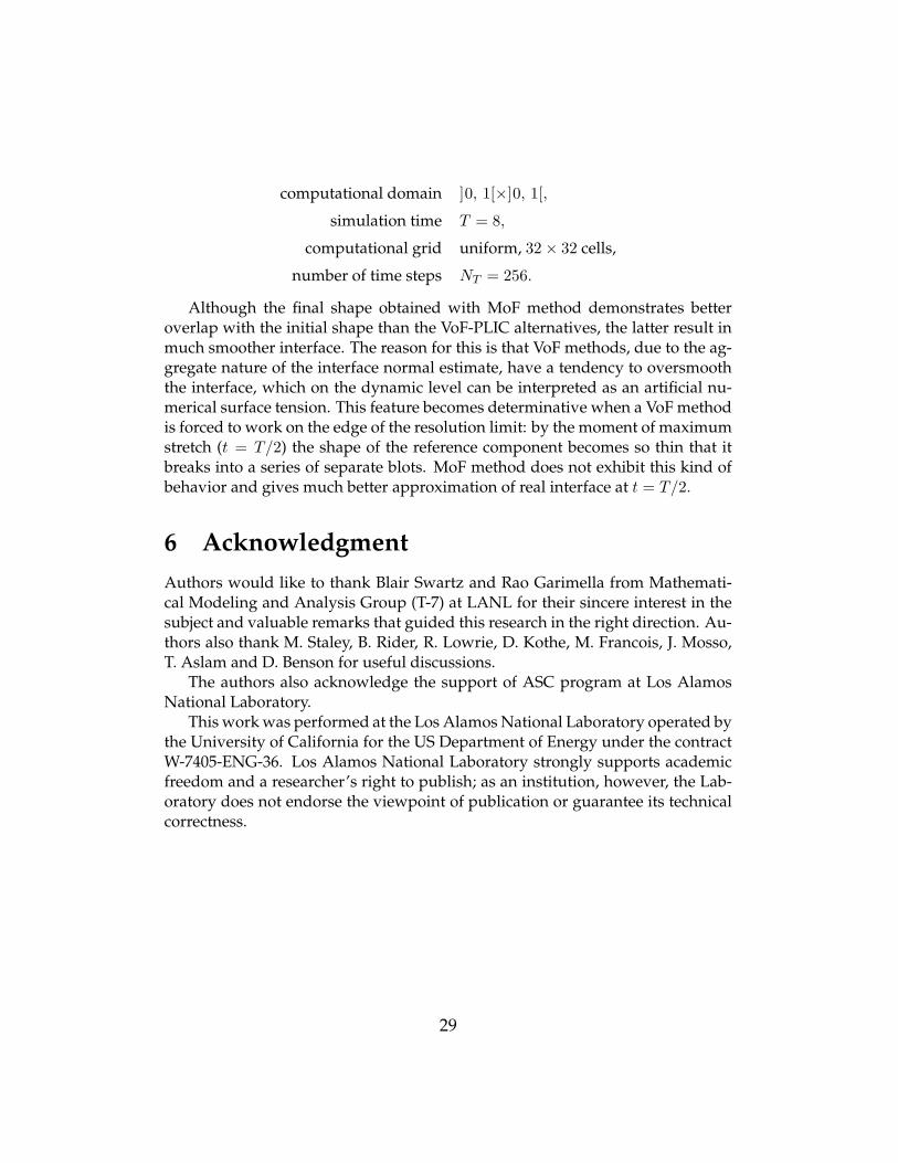
computational domain ]0, 1[×]0, 1[,
simulation time T = 8,
computational grid uniform, 32 × 32 cells,number of time steps NT = 256.
Although the final shape obtained with MoF method demonstrates betteroverlap with the initial shape than the VoF-PLIC alternatives, the latter result inmuch smoother interface. The reason for this is that VoF methods, due to the ag-gregate nature of the interface normal estimate, have a tendency to oversmooththe interface, which on the dynamic level can be interpreted as an artificial nu-merical surface tension. This feature becomes determinative when a VoF methodis forced to work on the edge of the resolution limit: by the moment of maximumstretch (t = T/2) the shape of the reference component becomes so thin that itbreaks into a series of separate blots. MoF method does not exhibit this kind ofbehavior and gives much better approximation of real interface at t = T/2.
6 AcknowledgmentAuthors would like to thank Blair Swartz and Rao Garimella from Mathemati-cal Modeling and Analysis Group (T-7) at LANL for their sincere interest in thesubject and valuable remarks that guided this research in the right direction. Au-thors also thank M. Staley, B. Rider, R. Lowrie, D. Kothe, M. Francois, J. Mosso,T. Aslam and D. Benson for useful discussions.
The authors also acknowledge the support of ASC program at Los AlamosNational Laboratory.
This work was performed at the Los Alamos National Laboratory operated bythe University of California for the US Department of Energy under the contractW-7405-ENG-36. Los Alamos National Laboratory strongly supports academicfreedom and a researcher’s right to publish; as an institution, however, the Lab-oratory does not endorse the viewpoint of publication or guarantee its technicalcorrectness.
29

7 AppendixAll VoF-PLIC algorithms introduced above rely on the list of adjacent cells thatinvolved in evaluation of the interface normal in a mixed cell. We consider twocells to be adjacent if they share an edge or a vertex.
Implementations of LSGQ and LVIRA follow exactly the descriptions givenin [2] and [14] respectively. The minimum of LVIRA objective function is consid-ered to be localized when the polar angle of the outward normal iterate stabilizeswithin tolφ = 10−6 radians.
Our implementation of Swartz algorithm is somewhat different from the orig-inal description given in [10]. This is actually the reason why we call it Swartz,not Mosso-Swartz.
The idea of the method is based on the fact that for a pair of adjacent mixedcell there exists a common linear interface that satisfies given volume fractions4).This common linear interface can be found by means of the following iterativeprocedure. Given initial VoF-PLIC approximation in both mixed cells, one has to:
1) connect the medians of interfaces with a straight segment;2) use the normal of this segment as a new iterate for the normal of common
linear interface;3) build a new linear interface in each cell using this normal;4) repeat this cycle until the direction of the common interface normal estab-
lishes within some small tolerance (we used tolφ = 10−6).The direction on the interface normal in a given mixed cell is defined as an aver-age of common interface normals due to all possible mixed neighbours.
In addition to this procedure, Mosso-Swartz algorithm [10] specifies an exter-nal iterative process that runs through the list of mixed cell and repeats the pro-cedure above in Gauss-Seidel manner, updating the interface normal in a mixedcell with the new averaged one as soon as the latter is evaluated. We came toconclusion that such an external iterations result in excessive numerical surfacetension, oversmooth the interface and decrease the resolution of the algorithm.Therefore in our implementation we do not use external iterations and also up-date the interface normals in Jacobi manner, i.e. only after all the normals havebeen evaluated from the original initial guess.
There are several important details about internal iterations that were not dis-cussed in the original paper.
4) For essential prerequisites see [21].
30

• A common interface for a given pair of adjacent cells and respective volumefractions is not unique. The iterative process may converge to either of them,depending on initial guess and implementation strategy.
• There are two choices of the outward normal on the segment that connects themedians of adjacent interfaces. What would be a reasonable deterministicrule for the choice?
• Are the common interfaces due to different neighbours averaged with equalweights or not?
It is clear that different choices of initial guess and implementation strategy resultin different PLIC reconstructions for the same set of volume fractions. We resolvethe issues above as follows:
• Our implementation of Swartz algorithm is seeded with the interfaces givenby LSGQ method.
• We do not proceed with internal iterations for a pair of adjacent mixed cellsif the initial outward normals differ by more than 45 degrees. Between thetwo opposite normals of the segment connecting the interface medians wechoose the one that has a positive projection on both initial outward nor-mals. If neither of two possible normals satisfy this criterion, the iterationsare aborted with void result.The rationale of this strategy comes clear if we start to look at Swartz iter-ations as at a second order accurate “upgrade” of initial interface approxi-mation: if two initial normals already differ significantly, then the commonlinear interface is highly unlikely to give an adequate approximation to theoriginal one, and therefore should not contribute to the average. This waythe “upgrade” kicks in only for those pairs of adjacent cells that carry infor-mation about the same smooth segment of original interface.
• All common normals are averaged with equal weights.One may argue that our interpretation of Swartz algorithm is subjective and
the quality of interface reconstruction it provides is not superior to the originalMosso-Swartz version. We may assure the reader that we tested a lot of variationsof the algorithm and found the one described above to be the most robust.
31

References[1] E. Aulisa, S. Manservisi, and R. Scardovelli. A surface marker algorithm
coupled to an area-preserving marker redistribution method for three-dimensional interface tracking. Journal of Computational Physics, 197(2):555–584, Jul 2004.
[2] T. J. Barth and D. C. Jespersen. The design and application of upwindschemes on unstructured meshes. In Proceedings of the 27th Aeroscience Meet-ing, Reno, NV, Jan 1989. AIAA.
[3] David J. Benson. Eulerian finite element methods for micromechanics of het-erogeneous materials: Dynamic prioritization of material interfaces. Com-puter Methods in Applied Mechanics and Engineering, 151:343–360, 1998.
[4] David J. Benson. Volume of fluid interface reconstruction methods for multi-material problems. Appl. Mech. Rev., 55(2):151–165, March 2002.
[5] J. Frederic Bonnans, J. Charles Gilbert, Claude Lemarechal, and Clau-dia A. Sagastizabal. Numerical Optimization: Theoretical and Practical Aspects.Springer–Verlag, Berlin Heidelberg, 2003.
[6] R. DeBar. Fundamentals of the KRAKEN code. Technical Report UCID-17366, Lawrence Livermore National Laboratory, 1974.
[7] D. Enright, R. Fedkiw, J. Ferziger, and I. Mitchell. A hybrid particle level setmethod for improved interface capturing. Journal of Computational Physics,183:83–116, 2002.
[8] W. H. McMaster. Computer codes for fluid-structure interactions. TechnicalReport UCRL-89724, Lawrence Livermore National Laboratory, 1984.
[9] J. P. Morris. Simulating Surface Tension with Smoothed Particle Hydro-dynamics. International Journal for Numerical Methods in Fluids, 33:333–353,2000.
[10] S. J. Mosso, B. K. Swartz, D. B. Kothe, and R. C. Ferrell. A Parallel, Volume-Tracking Algorithm for Unstructured Meshes. In P. Schiano, A. Ecer, J. Pe-riaux, and N. Satofuka, editors, Parallel Computational Fluid Dynamics: Algo-rithms and Results Using Advanced Computers, pages 368–375. Elsevier ScienceB.V., 1997.
[11] Stewart Mosso and Sean Clancy. A Geometrically Derived Priority Systemfor Young’s Interface Reconstruction. Technical Report LA-CP-95-0081, LosAlamos National Laboratory, 1995.
[12] Jorge Nocedal and Stephen J. Wright. Numerical Optimization. Springer–Verlag, New York, 1999.
32

[13] S. Osher and R. P. Fedkiw. Level Set Methods: An Overview and SomeRecent Results. Journal of Computational Physics, 169(2):463–502, May 2001.
[14] J. E. Pilliod and E. G. Puckett. Second-order Accurate Volume-of-Fluid Al-gorithms for Tracking Material Interfaces. Journal of Computational Physics,199(2):465–502, Sep 2004.
[15] William H. Press, Saul A. Teukolsky, William T. Vetterling, and Brian T. Flan-nery. Numerical Recipes in C: the Art of Scientific Computing, Second Edition.Cambridge University Press, New York, 1992.
[16] W. J. Rider and D. B. Kothe. Reconstructing Volume Tracking. Journal ofComputational Physics, 141:112–152, 1998.
[17] Martin Staley. CORE: Conservarive Remapper. Technical Report LA-UR-04-8104, Los Alamos National Laboratory, 2004.
[18] M. Sussman, A. S. Almgren, J. B. Bell, P. Colella, L. H. Howell, and M. L.Welcome. An Adaptive Level Set Approach for Incompressible Two-PhaseFlows. Journal of Computational Physics, 148:81–124, 1999.
[19] M. Sussman, E. Fatemi, P. Smereka, and S. Osher. Improved Level SetMethod for Incompressible Two-Phase Flows. Computers & Fluids, 27(5-6):663–680, Jun-Jul 1998.
[20] M. Sussman and E. G. Puckett. A Coupled Level Set and Volume-of-FluidMethod for Computing 3D and Axisymmetric Incompressible Two-PhaseFlows. Journal of Computational Physics, 162(2):301–337, Aug 2000.
[21] B. Swartz. The Second-Order Sharpening of Blurred Smooth Borders. Math-ematics of Computation, 52(186):675–714, Apr 1989.
[22] H. S. Udaykumar and W. Shyy. Grid-Supported Marker Particle Scheme forInterface Tracking. Numerical Heat Transfer, Part B (Fundamentals), 27(2):127–153, Mar 1995.
[23] D. L. Youngs. Time-Dependent Multi-Material Flow with Large Fluid Dis-tortion. In K. W. Morton and M. J. Baines, editors, Numerical Methods forFluid Dynamics, pages 273–285. Academic Press, 1982.
[24] D. L. Youngs. An Interface Tracking Method for a 3D Eulerian Hydrody-namics Code. Technical Report 44/92/35, AWRE, 1984.
33