
MOMENT CONNECTION: DESIGN OF W-SHAPE...
34
MOMENT CONNECTION: DESIGN OF W-SHAPE MOMENT BEAM TO W-SHAPE COLUMN FLANGE (1WAY) WITH SHEAR PLATE CONNECTION CALCULATION FOR MOMENT CONNECTION 2.xmcd 1 of 34
Transcript of MOMENT CONNECTION: DESIGN OF W-SHAPE...

MOMENT CONNECTION: DESIGN OF W-SHAPE MOMENT BEAM TO
W-SHAPE COLUMN FLANGE (1WAY) WITH SHEAR PLATE
CONNECTION
CALCULATION FOR MOMENT CONNECTION 2.xmcd 1 of 34

I. DESIGN DATA AND LOAD ( ASD - AISC 14th Edition )
W14X193 - A992COLUMN PROPERTIES (col):
Fycol 50 ksi⋅= dcol 15.5 in⋅= twcol 0.89 in⋅= k1col 1.688 in⋅=
Fucol 65 ksi⋅= bfcol 15.7 in⋅= tfcol 1.44 in⋅= kcol 2.75 in⋅=
E 29000ksi:=
Fybm 50 ksi⋅= dbm 18.2 in⋅= twbm 0.415 in⋅= k1bm 0.813 in⋅=
Fubm 65 ksi⋅= bfbm 7.56 in⋅= tfbm 0.695 in⋅= kbm 1.375 in⋅=
Length of Beam, Lbm 20ft:=
A36SHEAR PLATE (pl):
Fypl 36 ksi⋅= Fupl 58 ksi⋅= Thickness of
Plate:tpl
3
4in:=
A572-50 (AS REQUIRED) (Full Depth)STIFFENER PLATE (st):
Fyst 50 ksi⋅= bstgiv 7.25 in⋅= tst 1in:= clip 1in:=
Fust 65 ksi⋅= Lstgiv 12.5 in⋅= nst 2:=
A36 (AS REQUIRED) (Extended)DOUBLER PLATE (dp):
Fydp 36 ksi⋅= Fudp 58 ksi⋅= tdp3
8in⋅= ndp 1:=
Length of Doubler Plate,
Ldp Ceil dbm 2tst−1
4in,
:=
Ldp 16.25 in⋅=
W18X60 - A992BEAM PROPERTIES (bm):
CALCULATION FOR MOMENT CONNECTION 2.xmcd 2 of 34

BOLTS:
For Shear Plate to Beam Connection:
Bolt Diameter, dbpl 1 in⋅= Bolt_Typepl "A490-SC-SSLT-CLASS_A"=
Bolt Shear Strength, Λrvpl 14.464 kips⋅= Conn_typepl "Slip Critical-type"=
w5 Ceil3
4tst⋅
1
16in,
:=
Gap between edge of
beam to edge of support,
gap1
2in:= Hole diameter:
Shear Plate,Beam Web Edge
Distance,
Lehbmw 1.5 in⋅=hdplv 1.125 in⋅= hdplh 1.375 in⋅=
Plate Vertical Edge
Distance,
Levpl 1.5 in⋅=Beam Web,
Plate Horizontal Edge
Distance,
Lehpl 1.5 in⋅= hdbmw 1.125 in⋅=
Bolt Vertical Spacing, spl 3 in⋅=
Bolt Horizontal Spacing
(For Multiple bolt
lines),
svpl 3 in⋅=
number of bolt rows: nrpl 5:=
number of vertical bolt lines: nvpl 2:=
total number of bolts: npl nrpl nvpl⋅:= npl 10=
Bolt First Down from top of beam, D1 3.25 in⋅=
WELDS: E70xx LH
Fuw 70 ksi⋅= Weld Size
Shear Plate to
Column,w1 Ceil
5
8tpl⋅
1
16in,
1
2in⋅=:=
Doubler Plate to Column
Flange (As Req'd),w2 Ceil
5
8tdp⋅
1
16in,
1
4in⋅=:=
Stiffener Plate to Column
Flange (As Req'd),w4 Ceil
3
4tst⋅
1
16in,
:=
Stiffener Plate to Column
Web (As Req'd),
Λrnpl 44.375 kips⋅=Bolt Tensile Strength,
CALCULATION FOR MOMENT CONNECTION 2.xmcd 3 of 34

SAFETY AND RESISTANCE FACTORS:
Safety Factor, Ω (ASD)
Resistance Factor, φ (LRFD)
Modification Factor, Λ1
Ω= (IF ASD) Λ ϕ= (IF LRFD)
safety factor resistance factor modification factor
For tension rupture, Ωtr 2.00= ϕtr 0.75= Λtr 0.50=
For tension yielding, Ωty 1.67= ϕty 0.90= Λty 0.60=
For compression, Ωc 1.67= ϕc 0.9= Λc 0.60=
For shear, Ωv 1.67= ϕv 0.90= Λv 0.60=
For fillet weld
(shear),
Ωvw 2.00= ϕvw 0.75= Λvw 0.50=
For shear rupture, Ωvr 2.00= ϕvr 0.75= Λvr 0.50=
For shear yielding, Ωvy 1.50= ϕvy 1.00= Λvy 0.67=
For bearing, Ωbrg 2.00= ϕbrg 0.75= Λbrg 0.50=
For web compression
buckling,
Ωcb 1.67= ϕcb 0.90= Λcb 0.60=
For web crippling, Ωcr 2.00= ϕcr 0.75= Λcr 0.50=
For web yielding, Ωwy 1.50= ϕwy 1.00= Λwy 0.67=
For flexural local
buckling,
Ωb 1.67= ϕb 0.9= Λb 0.60=
For partial penetration
weld(shear),
Ωvwp 2.00= ϕvwp 0.75= Λvwp 0.50=
For partial penetration
weld(tension),
Ωtwp 1.88= ϕtwp 0.8= Λtwp 0.53=
CALCULATION FOR MOMENT CONNECTION 2.xmcd 4 of 34

APPLIED LOADS:
BEAM
% UDL, UDL 0.5:=
Beam Shear Load, Vbm Vgiv
2 Λb⋅ Fybm⋅ Zxbm⋅
Lbm
+ 80.689 kip⋅=:=
Pgiv 0kips:=
Beam Axial Load, Pbm 0.00 kips⋅=
% Moment Capacity, Mcap 1:=
Given Moment Load, Mgiv 0kips ft⋅:=
100% M.cap Moment Load, Mbm 306.89 kips ft⋅⋅=
COLUMN
Axial Load, Pucol 0kips:=
Story Shear, Vs 0kips:=
Given Axial Load
(if any),
Given Shear Load
(if any),
Vgiv 50kips:=
CALCULATION FOR MOMENT CONNECTION 2.xmcd 5 of 34

II. CALCULATIONS:
A. BEAM TO COLUMN FLANGE CONNECTION
1. Forces acting on the Connection
@ Beam Flange,
Ff
Pbm
2
Mbm
dbm tfbm−+:=
Ff 210.376 kips⋅=
2. Beam Flange to Column Flange Connection
Length of connection,
Lwf min bfbm bfcol, ( ):=
Complete Penetration Groove Weld Capacity,
Rwcpb Λty min Fycol Fybm, ( )⋅ tfbm⋅ Lwf⋅:=
Rwcpb 157.311 kips⋅= Ff 210.376 kips⋅=
RESULT = CJP weld can still fully developed the flange force
B. BEAM WEB CHECK
1. Bolt Bearing Capacity on Beam
(AISC 13th Ed. Chapter J, Section J3.10, page 16.1-111)
Bearing Area,
Abrgbm dbpl twbm⋅:=
Abrgbm 0.415 in2⋅=
Bolt centerline distance from face of support,
ab gap Lehbmw+ 0.5 nv 1−( ) sv⋅+:=
ab 3.5 in⋅=
Eccentric Load Coefficient,
(Table 7-7, AISC 13th Ed.)
C 7.292=
CALCULATION FOR MOMENT CONNECTION 2.xmcd 6 of 34
Allowable Bearing Strength using edge distance,(J3-6a,J3-6c)
Fbe Fubm min 1.0 D1 0.5 hdbmw⋅−( )⋅ twbm⋅ 2.0 Abrgbm⋅, hdbmw hdls≥if
min 1.2 D1 0.5 hdbmw⋅−( )⋅ twbm⋅ 2.4 Abrgbm⋅, otherwise
⋅:=
Fbe 64.74 kips⋅=
Allowable Bearing Strength using bolt spacing,(J3-6a,J3-6c)
Fbs Fubm min 1.0 spl hdbmw−( )⋅ twbm⋅ 2.0 Abrgbm⋅, hdbmw hdls≥if
min 1.2 spl hdbmw−( )⋅ twbm⋅ 2.4 Abrgbm⋅, otherwise
⋅:=
Fbs 60.694 kips⋅=
Bolt Bearing Capacity,
Rbrgbm Λbrg
C
nr⋅ Fbe Fbs nr 1−( )+[ ]⋅
:=
Rbrgbm 224.252 kips⋅= Vbm 80.689 kips⋅=
RESULT = Bearing Capacity > Force Applied,OK
2. Shear Capacity of Beam
(AISC 14th Ed. Specifications, Chapter G, Section G2.1, pages 16.1-67 to
16.1-69)
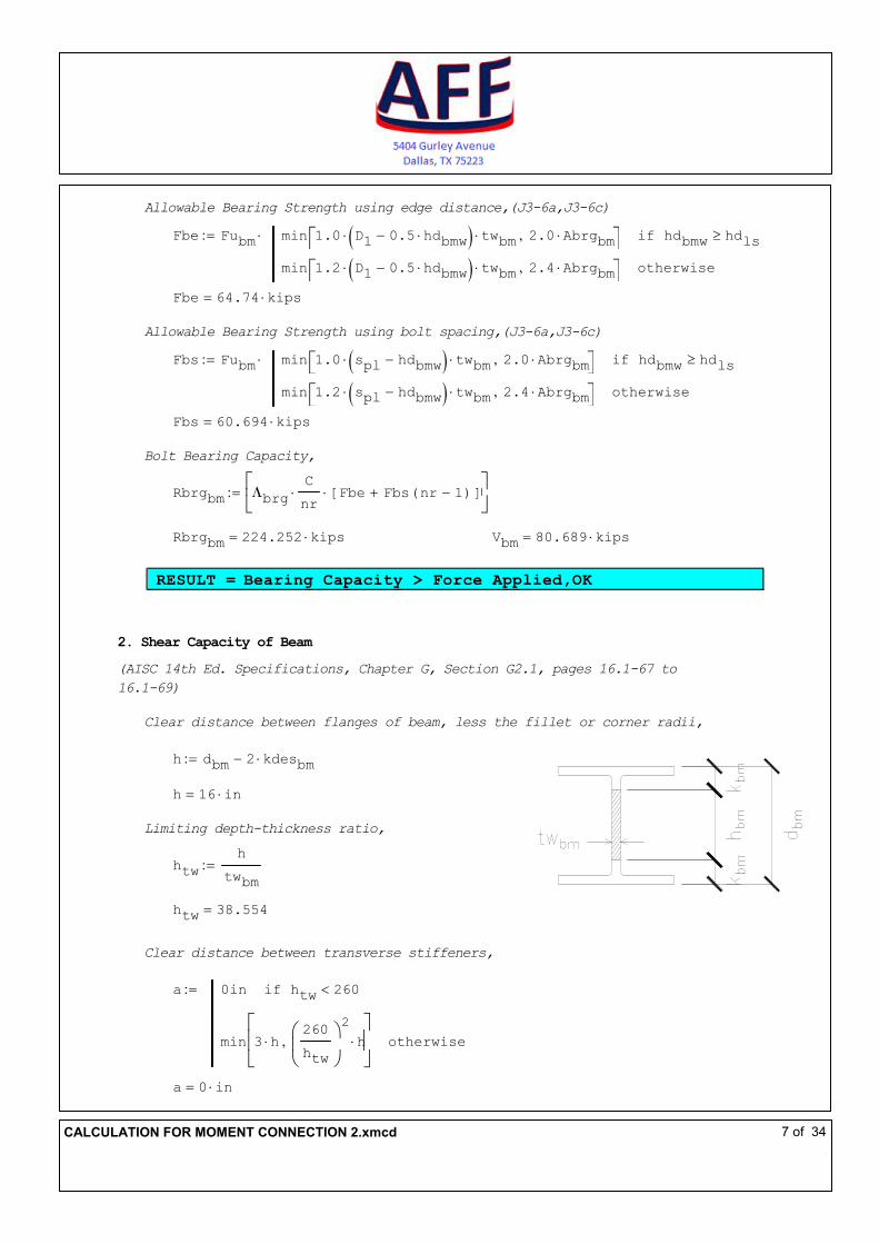
Clear distance between flanges of beam, less the fillet or corner radii,
h dbm 2 kdesbm⋅−:=
h 16 in⋅=
Limiting depth-thickness ratio,
htw
h
twbm
:=
htw 38.554=
Clear distance between transverse stiffeners,
a 0in htw 260<if
min 3 h⋅260
htw
2
h⋅,
otherwise
:=
a 0 in⋅=
CALCULATION FOR MOMENT CONNECTION 2.xmcd 7 of 34

Web plate buckling coefficient,
kv 5 htw 260<if
55
a
h
2+ otherwise
:=
(G2-6)
kv 5=
Web shear coefficient,
Cv 1 htw 1.1kv E⋅
Fybm
⋅≤if
1.1kv E⋅
Fybm
⋅
htw
1.1kv E⋅
Fybm
⋅ htw< 1.37kv E⋅
Fybm
⋅≤if
1.51 E⋅ kv⋅
htw2Fybm
1.37kv E⋅
Fybm
⋅ htw<if
:=(G2-3)
(G2-4)
(G2-5)
Cv 1=
Shear Capacity of Section,
Rvbm Λvbm 0.6⋅ Fybm⋅ dbm⋅ twbm⋅ Cv⋅:= (G2-1)
Rvbm 151.06 kips⋅= Vbm 80.689 kips⋅=
RESULT = Shear Capacity of Section > Force Applied, OK
C. BEAM TO SHEAR PLATE CHECK
1. Direct Bolt Shear Capacity
(AISC 13th Ed. Chapter J, Section J3.6, pages 16.1-108 to 16.1-109)
Shear Capacity per bolt,
Λrvpl 14.464 kips⋅=
Bolt Shear Capacity,
Rb C Λrvpl⋅:=
Rb 105.477 kips⋅= Vbm 80.689 kips⋅=
CALCULATION FOR MOMENT CONNECTION 2.xmcd 8 of 34

RESULT = Bolt Shear Capacity > Force Applied, OK
2. Check for Spacing
(AISC 13th Ed. Specifications Chapter J, Section J3.3 and J3.5, pages 16.1-106
to 16.1-108)
Vertical Spacing,
spl 3 in⋅=
smin 22
3dbpl⋅:=
smin 2.667 in⋅=
smax min 12in 24 min twbm tpl, ( )⋅, ( ):=
smax 9.960 in⋅=
RESULT = s > s.min & s < s.max, OK
Horizontal Spacing,
svpl 3 in⋅=
svmin 22
3dbpl⋅:=
svmin 2.667 in⋅=
svmax min 12in 24 min twbm tpl, ( )⋅, ( ):=
svmax 9.960 in⋅=
RESULT = sv > sv.min & sv < sv.max, OK
3. Check for Edge Distance
(AISC 13th Ed. Specifications Chapter J, Section J3.4 and J3.5, pages 16.1-106
to 16.1-108)
Vertical Edge Distance,
Levpl 1.5 in⋅=
Lemin 1.25 in⋅=
C2 0 in⋅=
CALCULATION FOR MOMENT CONNECTION 2.xmcd 9 of 34

Levmin Lemin C2+:=
Levmin 1.25 in⋅=
Levmax min 6in 12 tpl⋅, ( ):=
Levmax 6.000 in⋅=
RESULT = Lev > Lev.min & Lev < Lev.max, OK
Horizontal Edge Distance,
Lehpl 1.5 in⋅=
Lehbmw 1.5 in⋅=
Lemin 1.25 in⋅=
Lehminpl 1.375 in⋅=
Lehminbm 1.25 in⋅=
Lehmaxpl min 6in 12 tpl⋅, ( ):=
Lehmaxpl 6.000 in⋅=
Lehmaxbm min 6in 12 twbm⋅, ( ):=
Lehmaxbm 4.980 in⋅=
RESULT = Leh > Leh.min & Leh < Leh.max, OK
D. SHEAR PLATE CHECK
1. Check for Maximum Shear Plate Thickness
(AISC 13th Ed. Manual Part 10, page 10-103)
Exceptions for nv = 1 and nv = 2
tpldb
2
1
16+≤ twbm
db
2
1
16+≤
Lehpl 2 dbpl⋅≥ Lehbmw 2 dbpl⋅≥
RESULT = Check maximum thickness of plate
CALCULATION FOR MOMENT CONNECTION 2.xmcd 10 of 34

Coefficient for Eccentrically Loaded Bolts
(AISC 13th Ed. Manual Part 7, page 7-19)
C' 38.669 in⋅=
Area of Bolts
Abπ db
2⋅
4:=
Ab 0.785 in2⋅=
Length of Plate
Lpl nr 1−( ) s⋅ 2 Lev⋅+:=
Lpl 15 in⋅=
Maximum Thickness
tplmax
6 Fnv1 Ab⋅ C'⋅( )⋅
0.9 Fypl⋅ Lpl2⋅
:=
tplmax 0.691 in⋅= tpl 0.75 in⋅=
RESULT = Use the value of the maximum thickness of plate
Governing Shear Plate Thickness,
tplg
tpl tpl tplmax<if
tpl tpl tplmax=if
Floor tplmax
1
16in,
otherwise
Casepl 1=if
tpl otherwise
:=
tplg
11
16in⋅=
CALCULATION FOR MOMENT CONNECTION 2.xmcd 11 of 34
2. Bolt Bearing Capacity of Shear Plate
(AISC 13th Ed.Specifications Chapter J, Section J3.10,
page 16.1-111)
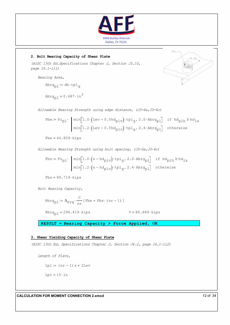
Bearing Area,
Abrgpl db tplg⋅:=
Abrgpl 0.687 in2⋅=
Allowable Bearing Strength using edge distance, (J3-6a,J3-6c)
Fbe Fupl min 1.0 Lev 0.5hdplv−( )⋅ tplg⋅ 2.0 Abrgpl⋅, hdplh hdls≥if
min 1.2 Lev 0.5hdplv−( )⋅ tplg⋅ 2.4 Abrgpl⋅, otherwise
⋅:=
Fbe 44.859 kips⋅=
Allowable Bearing Strength using bolt spacing, (J3-6a,J3-6c)
Fbs Fupl min 1.0 s hdplv−( )⋅ tplg⋅ 2.0 Abrgpl⋅, hdplh hdls≥if
min 1.2 s hdplv−( )⋅ tplg⋅ 2.4 Abrgpl⋅, otherwise
⋅:=
Fbs 89.719 kips⋅=
Bolt Bearing Capacity,
Rbrgpl Λbrg
C
nr⋅ Fbe Fbs nr 1−( )⋅+[ ]:=
Rbrgpl 294.419 kips⋅= V 80.689 kips⋅=
RESULT = Bearing Capacity > Force Applied, OK
3. Shear Yielding Capacity of Shear Plate
(AISC 13th Ed, Specifications Chapter J, Section J4.2, page 16.1-112)
Length of Plate,
Lpl nr 1−( )s 2Lev+:=
Lpl 15 in⋅=
CALCULATION FOR MOMENT CONNECTION 2.xmcd 12 of 34

Check if Length of Plate is acceptable,
(AISC 13th Ed, Manual Part 10, page 10-104)
Length "Plate Length is OK per AISC Requirements" Lpl 0.5 dbm 2kbm−( )≥if
"Increase Plate Length per AISC Requirements" otherwise
:=
Length "Plate Length is OK per AISC Requirements"=
Gross Shear Capacity,
Rvypl Λvy 0.6⋅ Fypl⋅ tplg⋅ Lpl⋅:= (J4-3)
Rvypl 148.5 kips⋅= V 80.689 kips⋅=
RESULT = Shear Yielding Capacity > Force Applied, OK
4. Shear Rupture Capacity of Shear Plate
(AISC 13th Ed, Specifications Chapter J, Section J4.2, page 16.1-112)
Net Area,
Anv Lpl nr hdplv⋅−( ) tplg⋅:=
Anv 6.445 in2⋅=
Shear Rupture Capacity,
Rvrpl Λvr 0.6⋅ Fupl⋅ Anv⋅:= (J4-4)
Rvrpl 112.148 kips⋅= V 80.689 kips⋅=
RESULT = Shear Rupture Capacity > Force Applied, OK
CALCULATION FOR MOMENT CONNECTION 2.xmcd 13 of 34

5. Block Shear Capacity of Shear Plate
(AISC 13th Ed. Specifications Chapter J, Section J4.3, pages 16.1-112 to
16.1-113 )
Reduction Factor, Ubs 1.0 nv 1=if
0.5 nv 1>if
:= (tension stress is uniform)
(tension stress is non-uniform)
Ubs 0.5=
Gross Shear Area
Agv nr 1−( ) s⋅ Lev+[ ] tplg⋅:=
Agv 9.281 in2⋅=
Net Tension Area
Ant Leh nv 1−( ) sv⋅+ nv 0.5−( ) hdplh⋅− tplg⋅:=
Ant 1.676 in2⋅=
Net Shear Area
Anv nr 1−( ) s⋅ Lev+ nr 0.5−( ) hdplv⋅− tplg⋅:=
Anv 5.801 in2⋅=
Block Shear Capacity of Plate, (J4-5)
Rbspl Λbs min 0.6Fupl Anv⋅ Ubs Fupl⋅ Ant⋅+ 0.6 Fypl⋅ Agv⋅ Ubs Fupl⋅ Ant⋅+, ( ):=
Rbspl 124.536 kips⋅= V 80.689 kips⋅=
RESULT = Block Shear Capacity > Force Applied, OK
CALCULATION FOR MOMENT CONNECTION 2.xmcd 14 of 34

6. Local Buckling Capacity of Shear Plate
(AISC 13th Ed., Manual Part 9, page 9-8 to 9-9)
Distance of bolt line to support,
ab gap Lehbm+:=
ab 2 in⋅=
Coefficient,
λ
Lpl Fypl⋅
10 tplg⋅ 475 280Lpl
ab
2
+⋅
1
ksi
⋅:=
λ 0.103=
Q 1 λ 0.7≤if
1.34 0.486 λ⋅− 0.7 λ< 1.41≤if
1.30
λ2
otherwise
:=
Q 1=
Allowable Buckling Stress,
Fcr Fypl Q⋅:=
Fcr 36 ksi⋅=
Gross Plastic Section Modulus,
Zxpl
tplg Lpl2⋅
4
:=
Zxpl 38.672 in3⋅=
CALCULATION FOR MOMENT CONNECTION 2.xmcd 15 of 34

Eccentricity,
epl ab:=
epl 2 in⋅=
Buckling Capacity,
Rbcpl Λb
Fcr Zxpl⋅
epl
⋅:=
Rbcpl 416.823 kips⋅= V 80.689 kips⋅=
RESULT = Local Buckling Capacity of plate > Applied Force, OK
7. Flexural Yielding Capacity with von-Mises shear reduction
(AISC 13th Ed., Manual Part 10, page 10-103/Muir, Larry and Hewitt,Christopher,
"Design of Unstiffened Extended Single-Plate Shear Connections", Engineering
Journal, 2nd Quarter 2009, page 69.)
Flexural Capacity,
Rfcpl
Λb Fypl⋅ Lpl⋅ tplg⋅
2.25 16
epl
Lpl
2
⋅+
:=
Rfcpl 139.64 kips⋅= V 80.689 kips⋅=
RESULT = This limit state is not applicable.
8. Flexural Rupture Capacity
(AISC 13th Ed., Steel Construction Manual Design Examples page IIA-84)
Net Plastic Section Modulus,
Znetpl
tpl Lpl2⋅
4
hdplv s⋅ tpl⋅ nr2
1−( )⋅
4−
tpl hdplv( )2⋅
4−
mod nr 2, ( ) 0>if
tpl Lpl2⋅
4
hdplv nr2⋅ s⋅ tpl⋅
4− mod nr 2, ( ) 0=if
:=
CALCULATION FOR MOMENT CONNECTION 2.xmcd 16 of 34

Znetpl 26.763 in3⋅=
Flexural Rupture Capacity,
(AISC 13th Ed., Manual Part 15, page 15-4)
Rfrpl
Λfr Fupl⋅ Znetpl⋅
epl
:=
Rfrpl 388.059 kips⋅= V 80.689 kips⋅=
RESULT = This limit state is not applicable.
9. Interaction of Shear Yielding, Shear Buckling, and Flexural Yielding of Plate
(AISC 14th Ed. Manual Part 10, page 10-104 to 10-105)
From AISC Manual Equation 10-5,
Vr
Vc
2Mr
Mc
2
+ 1.0≤
epl gap Lehbmw+ 0.5 nv 1−( ) sv⋅+:=
Vr V:=
Vr 80.689 kips⋅=
Mr Vr epl⋅:=
Mr 282.41 kips in⋅⋅=
Shear yielding,
Vc Λvy 0.6⋅ Fypl⋅ tplg⋅ Lpl⋅:=
Vc 148.5 kips⋅=
CALCULATION FOR MOMENT CONNECTION 2.xmcd 17 of 34

Flexural yielding,
Mc Λb Fypl⋅ Zxpl⋅:=
Mc 833.645 kips in⋅⋅=
Interaction,
Vr
Vc
2Mr
Mc
2
+ 0.41=
RESULT = Interaction < 1.0, OK
E. SHEAR PLATE TO COLUMN CHECK
1. Rupture Strength at Weld for Column
Rupture Strength at Weld,
Rvcol Λvr 0.6⋅ Fucol⋅ tfcol⋅ 2⋅ Lpl⋅:=
Rvcol 842.4 kips⋅= Vbm 80.689 kips⋅=
RESULT = Girder Web Capacity > Force Applied, OK.
F. COLUMN LOCAL CHECKS
1. Flange Local Bending
(AISC 14th Ed. Chapter J, Specifications Section J10.1, page 16.1-133)
Flange Force,
Ff 210.376 kips⋅=
Distance of Force to Column End,
Decol 36in:=
Local Bending Capacity,
Rfb Λfb 6.25⋅ tfcol2⋅ Fycol⋅ Decol 10 tfcol⋅≥if
0.5 Λfb⋅ 6.25⋅ tfcol2⋅ Fycol⋅ otherwise
:= (J10-1)
Rfb 388.024 kips⋅= Ff 210.376 kips⋅=
RESULT = Local Flange Bending Capacity > Force Applied, OK
CALCULATION FOR MOMENT CONNECTION 2.xmcd 18 of 34

2. Web Local Yielding
(AISC 14th Ed. Specifications, Chapter J, Section J10.2, page 16.1-134)
Bearing Length,
N tfbm:=
N 0.695 in⋅=
Web Yielding capacity,
Rwy Λwy Fycol twcol⋅ N 5 kdescol⋅+( )⋅ Decol dcol>if
Fycol twcol⋅ N 2.5 kdescol⋅+( )⋅ otherwise
:= (J10-2)
(J10-3)
Rwy 323.218 kips⋅= Ff 210.376 kips⋅=
RESULT = Web Yielding Capacity > Force Applied, OK
3. Column Web Crippling
(AISC 14th Ed. Specifications, Chapter J, Section J10.3, pages 16.1-134 to
16.1-135)
Web Crippling capacity,
Esq
E Fycol⋅ tfcol⋅
twcol
:=
N1 1 3N
dcol
⋅twcol
tfcol
1.5
⋅+:=
N2 14N
dcol
0.2−
twcol
tfcol
1.5
⋅+:=
Rwc Λcr 0.8twcol2N1⋅ Esq⋅ Decol
dcol
2≥if
0.4twcol2N1⋅ Esq⋅ Decol
dcol
2<
N
dcol
0.2≤∧if
0.4twcol2N2⋅ Esq⋅ Decol
dcol
2<
N
dcol
0.2>∧if
:= (J10-4)
(J10-5a)
(J10-5b)
Rwc 517.019 kips⋅= Ff 210.376 kips⋅=
RESULT = Web Crippling Capacity > Force Applied, OK
CALCULATION FOR MOMENT CONNECTION 2.xmcd 19 of 34

4. Web Panel Zone Shear
(AISC 14th Ed, Chapter J, Specifications Section J10.6, page 16.1-136 to 137)
Force Acting on the Web Panel Zone,
Vpz min
Mbm
dbm tfbm−
2Λb Fycol⋅ Zxcol⋅
dbm tfbm−,
Vs−:=
Vpz 210.376 kips⋅=
Column Strength,
Pc Fycol Agcol⋅ Code "LRFD"=if
0.60 Fycol⋅ Agcol⋅ Code "ASD"=if
:=
Pc 1704 kips⋅=
Web Panel Zone Shear Capacity,
Rvzcol Λv 0.6⋅ Fycol⋅ dcol⋅ twcol⋅ Pucol 0.40 Pc⋅≤if
Λv 0.6⋅ Fycol⋅ dcol⋅ twcol⋅ 1.4
Pucol
Pc
−
⋅ otherwise
:= J10 9−( )
J10 10−( )
Rvzcol 247.814 kips⋅= Vpz 210.376 kips⋅=
RESULT : Web Panel Zone Shear Capacity > Force Applied, OK
5. Shear Buckling of Column Web
(AISC 14th Ed, Chapter G, Section G2.1, page 16.1-67 to 16.1-69)
Minimum Thickness of Column Web based on shear buckling,
G2 1−( )twcolm
dcol 2 kdescol⋅−
2.24
Fycol
E⋅:=
twcolm 0.212 in⋅= twcol 0.89 in⋅=
h dcol 2kdescol−:=
htw
h
twcol
:=
CALCULATION FOR MOMENT CONNECTION 2.xmcd 20 of 34

a 0in htw 260<if
min 3 h⋅260
h
twcol
2
h⋅,
otherwise
:=
a 0 in⋅=
kv 5 htw 260≤if
55
a
h
2+ otherwise
:=
kv 5=
Cv 1h
twcol
1.1kv E⋅
Fycol
⋅≤if
1.1kv E⋅
Fycol
⋅
h
twcol
1.1kv E⋅
Fycol
⋅h
twcol
< 1.37kv E⋅
Fycol
⋅≤if
1.51 E⋅ kv⋅
h
twcol
2
Fycol
1.37kv E⋅
Fycol
⋅h
twcol
<if
:=
Cv 1=
Λvcol Λvy
h
twcol
2.24E
Fycol
⋅≤if
Λv otherwise
:=
Λvcol 0.667=
Shear Buckling Capacity,
Rvcol Λvcol 0.6⋅ Fycol⋅ Cv⋅ twcol⋅ dcol⋅:=
Rvcol 275.9 kips⋅= Vpz 210.376 kips⋅=
RESULT = Shear Buckling will not control, OK
CALCULATION FOR MOMENT CONNECTION 2.xmcd 21 of 34

G. REINFORCEMENT DESIGN FORCES
1. Required Strength for Doubler Plate
Vudp max Vpz min Rvzcol Rvcol, ( )− 0kips, ( ) twcol twcolm<if
max Vpz Rvzcol− 0kips, ( ) otherwise
:=
Vudp 0 kips⋅=
2. Stiffener Plate Design Force
Stiffener Plate Design Force,
Fstt max Ff min Rwy Rfb, ( )− 0kips, ( ) Lwf 0.15 bfcol⋅≥if
max Ff Rwy− 0kips, ( ) otherwise
:=
Fstt 0 kips⋅=
Fstc max Ff min Rwy Rwc, ( )− 0kips, ( ):=
Fstc 0 kips⋅=
Fst max Fstt Fstc, ( ):=
Fst 0 kips⋅=
Design Shear Force @ Column Web,
Fstw Fst:=
Fstw 0 kips⋅=
3. Column Web Thickness Check Due to Forces From Stiffener Plates
(Steel Design Guide Series 13, Chapter 4, Section 4.4.2, page 30)
CALCULATION FOR MOMENT CONNECTION 2.xmcd 22 of 34
twcolreq1
Fstw
Λvy 0.6⋅ Fycol⋅ dcol 2 kcol⋅−( )⋅ 4⋅:=
twcolreq1 0 in⋅=
twcolreq2
Fstw
Λvy 0.6⋅ Fycol⋅ dcol⋅ 2⋅:=
twcolreq2 0 in⋅=
twcolreq3
Fstw
Λvy 0.6⋅ Fycol⋅ dcol 2 kcol⋅−( )⋅ 2⋅:=
twcolreq3 0 in⋅=
twcolreq4
Fstw
Λvy 0.6⋅ Fycol⋅ dcol⋅:=
twcolreq4 0 in⋅=
Required Thickness of Column Web,
twcolreq max twcolreq3 twcolreq4, ( ) Vudp 0=if
max twcolreq1 twcolreq2, ( ) ndp 1=if
0 otherwise
otherwise
:=
twcolreq 0 in⋅= twcol 0.89 in⋅=
RESULT = NOT APPLICABLE, Stiffener Plate Not Required.
H. DOUBLER PLATE DESIGN
1. Required Doubler Plate Thickness
Thickness of Doubler Plate,
tdp 0in Vudp 0kips=if
tdp otherwise
:=
tdp 0 in⋅=
CALCULATION FOR MOMENT CONNECTION 2.xmcd 23 of 34
Based on Shear Buckling of Column Web,
tdpreq1 max
twcolm twcol−
ndp0in,
ndp 1≥if
0 otherwise
:=
tdpreq1 0 in⋅=
Based on Shear Yielding of Doubler Plate,
tdpreq2
Vudp
Λvy 0.6⋅ Fydp⋅ dcol⋅ ndp⋅:=
tdpreq2 0 in⋅=
Based on Shear Buckling of Doubler Plate,
tdpreq3
dcol 2 kdescol⋅−( )in
Fydp
ksi⋅
418in⋅:=
tdpreq3 0.164 in⋅=
Due to Forces at Stiffener Plate,
tdpreq4
Fstw
Λvy 0.6⋅ Fydp⋅ Lstgiv 2clip−( )⋅ 4⋅:=
tdpreq4 0 in⋅=
tdpreq5
Fstw
Λvy 0.6⋅ Fydp⋅ dcol⋅ 2⋅:=
tdpreq5 0 in⋅=
Required Thickness of Doubler Plate,
tdpreq max tdpreq1 tdpreq2, tdpreq3, tdpreq4, tdpreq5, ( ):=
tdpreq 0.164 in⋅= tdp 0 in⋅=
RESULT = NOT APPLICABLE, Doubler Plate Not Required.
CALCULATION FOR MOMENT CONNECTION 2.xmcd 24 of 34

2. Weld Check for Each Doubler Plate Connection to Column Flange
a. Doubler Plate to Column Flange Connection Using Fillet Weld
Minimum Thickness of Doubler Plate for Fillet Welding,
tdpminw kcol tfcol−:=
tdpminw 1.31 in⋅= tdp 0 in⋅=
RESULT = NOT APPLICABLE, Doubler Plate Not Required.
No. of Weld side, nws 1:=
Minimum weld size,
(AISC 14th Ed, Chapter J, Specifications Section J2.2b, Table J2.4)
wmin 0 in⋅= w2
1
4in⋅=
RESULT = NOT APPLICABLE, Doubler Plate Not Required.
Shear Strength,
For Column:
Rvcol Λvr 0.6⋅ Fucol⋅ tfcol⋅ nws⋅:=
Rvcol 28.08kips
in⋅=
For Doubler Plate:
Rvdp Λvr 0.6⋅ Fudp⋅ tdp⋅:=
Rvdp 0kips
in⋅=
For Weld:
Rvw Λvw 0.6⋅ Fuw⋅ sin 45deg( )⋅ nws⋅:=
Rvw 14.849 ksi⋅=
Maximum effective weld size,
weff
min Rvcol Rvdp, ( )Rvw
:=
weff 0 in⋅=
CALCULATION FOR MOMENT CONNECTION 2.xmcd 25 of 34
Length of Weld,
Lwdp Ldp:=
Weld Capacity,
Rwdp Λvw 0.6⋅ Fuw⋅ sin 45deg( )⋅ nws⋅ min w2 weff, ( )⋅ Lwdp⋅:=
Rwdp 0 kips⋅= Vudp 0 kips⋅=
RESULT = NOT APPLICABLE, Doubler Plate Not Required.
b. Doubler Plate to Column Flange Connection Using Complete Pen
Complete Penetration Groove Weld Capacity,
Rwcps Λvy min Fycol Fydp, ( )⋅ 0.60⋅ Ldp⋅ tdp⋅ ndp⋅:=
Rwcps 0 kips⋅= Vudp 0 kips⋅=
RESULT = NOT APPLICABLE, Doubler Plate Not Required.
I. STIFFENER PLATE DESIGN
1. Width of Stiffeners
Maximum Width of Stiffener Plates
bstmax Floor 0.5 bfcol twcol−( )⋅ tdp−1
4in,
:=
bstmax 7.25 in⋅=
Minimum Width of Stiffener Plates
(AISC 14th Ed, Specifications Chapter J, Section J10.8, page 16.1-138)
bstmin
Lwf
3
twcol
2tdp+
−:=
bstmin 2.075 in⋅=
Width of Stiffener Plates
bst min Floor max bstmin bstgiv, ( )1
4in,
bstmax,
:=
bst 7.25 in⋅=
CALCULATION FOR MOMENT CONNECTION 2.xmcd 26 of 34

2. Length of Stiffeners
Minimum Length of Stiffener Plates,
(Steel Design Guide Series 13, Chapter 4, Section 4.3.3, page 24)
Lstmin
dcol
2:=
Lstmin 7.75 in⋅=
Maximum Length of Stiffener Plates
Lstmax Floor dcol 2tfcol−1
4in,
:=
Lstmax 12.5 in⋅=
Length of Stiffener Plates
Lst min Floor max Lstmin Lstgiv, ( )1
4in,
Lstmax,
:=
Lst 12.5 in⋅=
3. Thickness of Stiffeners
Thickness of Stiffener Plate,
tst 1 in⋅=
Minimum Thickness of Stiffener Plate,
(AISC Specifications 14th Ed, Chapter J, Section J10.8, page 16.1-138)
(Steel Design Guide Series 13, Chapter 4, Section 4.3.2, page 23)
tstmin max
tfbm
2
bst
16,
:=
tstmin 0.453 in⋅= tst 1 in⋅=
RESULT = NOT APPLICABLE, Stiffener Plate Not Required
4. Tension Capacity of Stiffener Plate
(AISC 14th Ed. Specifications, Chapter J, Section J4.1, page 16.1-128)
Tension Capacity,
Rtyst Λty Fyst⋅ 2⋅ bst clip−( ) tst⋅:=
Rtyst 374.251 kips⋅= Fstt 0 kips⋅=
RESULT = NOT APPLICABLE, Stiffener Plate Not Required
CALCULATION FOR MOMENT CONNECTION 2.xmcd 27 of 34

5. Bearing Capacity of Stiffener Plate
(AISC 14th Ed. Chapter J, Specifications Section J7, page 16.1-131)
Bearing Capacity,
Rcbst 1.8Λbrg Fyst⋅ 2⋅ bst clip−( ) tst⋅:=
Rcbst 562.5 kips⋅= Fstc 0 kips⋅=
RESULT = NOT APPLICABLE, Stiffener Plate Not Required
6. Shear Yielding Capacity of Stiffener Plate
(AISC 14th Ed. Specifications, Chapter J, Section J4.2, page 16.1-129)
Shear Yielding,
Rvyst Λvy 0.6⋅ Fyst⋅ tst⋅ 2⋅ Lst 2clip−( )⋅:=
Rvyst 420 kips⋅= Fstw 0 kips⋅=
RESULT = NOT APPLICABLE, Stiffener Plate Not Required
7. Weld Check for Stiffener Plate to Column Flange
a. Forces Acting on the Connection
Fst 0 kips⋅=
b. Stiffener Plate to Column Flange Connection Using Fillet Weld
No. of Weld side, nws 2:=
Minimum weld size,
(AISC 14th Ed, Chapter J, Specifications Section J2.2b, Table J2.4)
wmin
5
16in⋅= w4
3
4in⋅=
RESULT = NOT APPLICABLE, Stiffener Plate Not Required
Shear Strength,
For Column:
Rvcol Λvr 0.6⋅ Fucol⋅ tfcol⋅ nws⋅:=
Rvcol 56.16kips
in⋅=
CALCULATION FOR MOMENT CONNECTION 2.xmcd 28 of 34

For Stiffener Plate:
Rvst Λtr Fust⋅ tst⋅:=
Rvst 32.5kips
in⋅=
For Weld:
Rvw Λvw 1.5⋅ 0.6⋅ Fuw⋅ sin 45deg( )⋅ nws⋅:=
Rvw 44.548 ksi⋅=
Maximum effective weld size,
weff
min Rvcol Rvst, ( )Rvw
:=
weff 0.73 in⋅=
Length of Weld,
Lwf max bst clip− 0, ( ):=
Lwf 6.25 in⋅=
Weld Capacity,
Rwf Λvw 1.5⋅ 0.6⋅ Fuw⋅ sin 45deg( )⋅ nws⋅ min w4 weff, ( )⋅ Lwf⋅ nst⋅:=
Rwf 406.25 kips⋅= Fst 0 kips⋅=
RESULT = NOT APPLICABLE, Stiffener Plate Not Required
c. Stiffener Plate to Column Flange Connection Using Partial Pen
Root Face,
f1
8in:=
End Preparation
tfpS tst f−:=
tfpS
7
8in⋅=
CALCULATION FOR MOMENT CONNECTION 2.xmcd 29 of 34

Effective Weld Thickness
tfpE tfpS 0−:=
tfpE
7
8in⋅= tfpmin
5
16in⋅=
RESULT = NOT APPLICABLE, Stiffener Plate Not Required
Partial Penetration Groove Weld Capacity,
Rwpps min ΛtrFust ΛvrFucol nws⋅ 0.6⋅, Λtwp Fuw 0.60⋅, ( ) Lwf⋅ tfpE⋅ nst⋅:=
Rwpps 244.348 kips⋅= Fst 0 kips⋅=
RESULT = NOT APPLICABLE, Stiffener Plate Not Required
d. Stiffener Plate to Column Flange Connection Using Complete Pen
Complete Penetration Groove Weld Capacity,
Rwcps Λty min Fycol Fyst, ( )⋅ Lwf⋅ tst⋅ nst⋅:=
Rwcps 374.251 kips⋅= Fst 0 kips⋅=
RESULT = NOT APPLICABLE, Stiffener Plate Not Required
8. Weld Check for Stiffener Plate to Column Web
a. Force Acting on the Connection
Fstw 0 kips⋅=
b. Stiffener Plate to Column Web Connection Using Fillet Weld
No. of Weld side, nws 2:=
Minimum weld size,
(AISC 14th Ed, Chapter J, Specifications Section J2.2b, Table J2.4)
wmin
5
16in⋅= w5
3
4in⋅=
RESULT = NOT APPLICABLE, Stiffener Plate Not Required
CALCULATION FOR MOMENT CONNECTION 2.xmcd 30 of 34

Shear Strength,
For Column:
Rvcol Λvr 0.6⋅ Fucol⋅twcol
2⋅ nws⋅:=
Rvcol 17.355kips
in⋅=
For Stiffener Plate:
Rvst Λvr 0.6⋅ Fust⋅ tst⋅:=
Rvst 19.5kips
in⋅=
For Weld:
Rvw Λvw 0.6⋅ Fuw⋅ sin 45deg( )⋅ nws⋅:=
Rvw 29.698 ksi⋅=
Maximum effective weld size,
weff
min Rvcol Rvst, ( )Rvw
:=
weff 0.584 in⋅=
Length of weld,
Lww Lst 2 clip⋅−:=
Lww 10.5 in⋅=
Weld Capacity,
Rww Λvw 0.6⋅ Fuw⋅ sin 45deg( )⋅ min weff w5, ( )⋅ Lww⋅ nws⋅ nst⋅:=
Rww 364.455 kips⋅= Fstw 0 kips⋅=
RESULT = NOT APPLICABLE, Stiffener Plate Not Required
c. Stiffener Plate to Column Web Connection Using Partial Pen
Root Face,
f1
8in:=
CALCULATION FOR MOMENT CONNECTION 2.xmcd 31 of 34

End Preparation
tfpS tst f−:=
tfpS
7
8in⋅=
Effective Weld Thickness
tfpE tfpS 0−:=
tfpE
7
8in⋅= tfpmin
5
16in⋅=
RESULT = NOT APPLICABLE, Stiffener Plate Not Required
Partial Penetration Groove Weld Capacity,
Rwpps2 min ΛvrFust Λvr Fucol, Λvwp Fuw, ( ) 0.6⋅ Lww⋅ tfpE⋅ nst⋅:=
Rwpps2 358.312 kips⋅= Fstw 0 kips⋅=
RESULT = NOT APPLICABLE, Stiffener Plate Not Required
d. Stiffener Plate to Column Web Connection Using Complete Pen
Complete Penetration Groove Weld Capacity,
Rwcps2 Λvy min Fycol Fyst, ( )⋅ 0.60⋅ Lww⋅ tst⋅ nst⋅:=
Rwcps2 420 kips⋅= Fstw 0 kips⋅=
RESULT = NOT APPLICABLE, Stiffener Plate Not Required
CALCULATION FOR MOMENT CONNECTION 2.xmcd 32 of 34

III. DETAILS
A. SKETCH
MOMENT CONNECTION: DETAIL OF W-SHAPE MOMENT BEAM TO
W-SHAPE COLUMN FLANGE (1WAY) WITH SHEAR PLATE
CONNECTION
CALCULATION FOR MOMENT CONNECTION 2.xmcd 33 of 34

B. TABLE: MOMENT CONNECTION SCHEDULE:
Size Grade
W18X60 A992 306 39/44 0 80 42/61 0 0
Beam
Moment
Load, Mbm
(kip-ft)
Beam Axial
Load, Pbm
(kips)
Beam
Shear
Load, Vbm
(kips)
Column
Axial Load,
Pucol (kips)
Beam Story
Shear,
Vs
(kips)
Size Gradetdp
(in)Grade
w2
(in)ndp
tst
(in)Grade
w4
(in)
w5
(in)
W14X193 A992 NR NR NR NR NR NR NR NR
Remarks
Stiffener Plate Conn.Doubler Plate Conn.Column
Note:
1. All Welds are E70XX LH
2. NR - Not Required
IV. REFERENCES
Steel Construction Manual ( 14th )- ASD American Institute of Steel
Construction, Inc. 2010
tpl
(in)Gradepl w1 (in)
dbpl
(in)Type nrpl nvpl
3/4 A36 1/2 1 A490-SC-SSLT-
CLASS_A5 2 1 1/2 1 1/2 1 1/2 3 1/4 1/2
D1
(in)
Shear Plate Bolts at Shear PlateWeldLehbmw
(in)
gap
(in)
Levpl
(in)
Levpl
(in)
CALCULATION FOR MOMENT CONNECTION 2.xmcd 34 of 34