Dr. mohamad nor bin mohamad taib pemasaran antarabangsa ipgm (vietnam)

MICROSTRIP PATCH ANTENNA
MOHAMAD AIMAN BIN MD KASSIM
UNIVERSITI TEKNIKAL MALAYSIA MELAKA

i
MICROSTRIP PATCH ANTENNA
MOHAMAD AIMAN BIN MD KASSIM
This Report Is Submitted In Partial Fulfillment of Requirements for the Bachelor
Degree of Electronic Engineering (Wireless Communication) With Honours
Fakulti Kejuruteraan Elektronik dan Kejuruteraan Komputer
Universiti Teknikal Malaysia Melaka
June 2012

ii

iii

iv

v
Specially dedicated to
My beloved parents, brother, sister, friend and my lover who have encouraged,
guided and inspired me throughout my journey of education

vi
ACKNOWLEDGEMENT
First of all, I would like to take this opportunity to express my deepest
gratitude to my beloved project supervisor, Pn. Mawarni Binti Mohamed Yunus for
her guidance in correcting my mistakes, encouragement and endurance during the
whole course of this project. It is indeed my pleasure for her undivided support,
invaluable advices and enthusiastic support to make my project a successfully done. I
would like to extend my gratitude is to my beloved family, especially my parents for
their fullest support throughout 4 year study in Universiti Teknikal Malaysia Melaka
(UTeM). It is because of them, I am the person who I am today, for all their moral
support all these while so that I will be able to complete my project successfully. My
appreciation also to my friends especially to my course mates, for their technical
advice and material aid. To all the people that are assisting me directly and indirectly
in this project, once again I would like to say a big thank you. Thank you.

vii
ABSTRACT
This project is about to design of a microstrip patch antenna on the non-
conductive textile substrates at the operating frequency 2.45 GHz which is for
wireless local area network (WLAN) application. There are certain fabric materials
in the market that can be use to patch the microstrip antenna such as Nora, felt, fleece
and etc. Those fabric materials have relative permittivity characteristics that make it
suitable for wearable antenna. The main objective of this project is to design,
simulate, fabricate and analyze the microstrip patch antenna at frequency 2.45 GHz
using textile as the substrate. The proposed fabric material for this project is felt
fabric. The felt fabric is selected because it has constant thickness and stable relative
permittivity. The 2.45 GHz unlicensed band is utilized for the development of this
wearable antennas. The used of FR4 as the substrate in conventional antenna is not
suitable for wearable system because of limited body movement problem. To
overcome this problem is by changing FR4 substrate with textile substrate. The
measurement results for fabricated antenna have a slightly different with the
simulation result. The frequency of the simulation result is 2.45 GHz, but the
frequency of measured result has shifted to 2.6 GHz. However, some
recommendation was made in order to improve the performance of the antenna.
.

viii
ABSTRAK
Projek ini adalah untuk merekabentuk Antena Tompok Jalur Mikro yang
menggunakan tekstil bukan pengalir sebagai substrat. Antena ini beroperasi pada
frekuensi 2.45 GHz yang mana bertujuan untuk aplikasi WLAN. Terdapat beberapa
jenis kain tertentu yang berada di pasaran yang boleh digunakan sebagai substrat
untuk Antena Tompok Jalur Mikro. Contohnya ialah Nora, felt fleece dan lain-lain.
Tekstil ini mempunyai ciri-ciri ketelusan relatif (𝜀𝑟 ) yang menjadikan ia sesuai
untuk antena boleh dipakai. Objektif yang utama dalam projek ini adalah untuk
merekabentuk, simulasi, fabrikasi dan analisis Antena Tompok Jalur Mikro pada
frekuensi 2.45 GHz yang menggunakan tekstil sebagai substrat. Kain yang
dicadangkan dalam projek ini adalah kain felt. Kain ini dipilih kerana mempunyai
ketebalan dan ketelusan relatif yang stabil. Penggunaan FR4 sebagai substrat pada
antenna yang sedia ada tidak sesuai untuk sistem yang boleh dipakai kerana
menyebabkan masalah pergerakan badan terhad. Langkah untuk mengatasi masalah
ini adalah dengan menggantikan FR4 dengan tekstil sebagai substrat. Terdapat
sedikit perbezaan diantara hasil ujian untuk fabrikasi antena dengan hasil untuk
simulasi antena. Frekuensi yang diperoleh dari hasil simulasi ialah 2.45 GHz, tetapi
frekuensi yang diperoleh dari hasil ujian untuk fabrikasi antenna ialah 2.6 GHz.
Walaubagaimanapun, cadangan telah dibuat untuk penambahbaikan prestasi Antena
Tompok Jalur Mikro ini.

ix
TABLE OF CONTENT
CHAPTER TITLE PAGE
PROJECT TITLE i
REPORT STATUS FORM ii
DECLARATION iii
DEDICATION v
ACKOWLEDGEMENT vi
ABSTRACT vii
ABSTRAK viii
TABLE OF CONTENT ix
LIST OF TABLE xii
LIST OF FIGURE xiii
I INTRODUCTION 1
1.1 Project Background 1
1.2 Problem Statement 2
1.3 Objectives Project 2
1.4 Scope of work 3
1.5 Report Structure 3
1.6 Methodology 4
II LITERATURE REVIEW 5
2.1 Introduction 5
2.2 Microstrip Patch Antenna Basic 6
2.3 Microstrip Patch Antenna Properties 8

x
2.3.1 Radiation Pattern 8
2.3.2 Half-power Beamwidth (HPBW) 10
2.3.3 Bandwidth 11
2.3.4 Return Loss and VSWR 11
2.3.5 Gain and Directivity 12
2.3.6 Polarization 12
2.4 Microstrip Antenna Design Analysis 13
2.4.1 Transmission-Line Model 13
2.4.1.1 Fringing Effects 14
2.4.1.2 Effective length, Resonant Frequency, and
Effective Width 14
2.4.2 Cavity Model 15
2.5 Microstrip Patch Feeding Techniques 17
2.5.1 Microstrip Line Feed 17
2.5.2 Coaxial Feed 18
2.5.3 Aperture Coupled Feed 19
2.5.4 Proximity Coupled Feed 19
2.6 Microstrip Patch Textile Antenna 21
2.7 Previous Work 22
2.7.1 Dual-band Wearable Textile Antenna 22
2.7.2 Wearable Textile Antenna: Fabric Investigations 24
2.7.3 A Review of Wearable Antenna 25
III METHODOLOGY 27
3.1 Methodology 27
3.2 Flow Chart of Project 28
3.3 Microstrip Patch Textile Antenna Design 29
3.3.1 Design Specification 29
3.3.2 Design Process 29
3.3.3 Fabric Material Selection 32
3.4 Calculation 33
3.4.1 Determination of Side Length and Wavelength 33

xi
3.4.2 Determination of Width and Length for 𝑍0 34
3.5 Project Planning 35
IV RESULT AND ANALYSIS 36
4.1 Introduction 36
4.2 Design Equilateral Triangular Microstrip Patch Antenna 37
4.3 Simulation Results 38
4.3.1 Return Loss 38
4.3.2 Radiation Pattern 40
4.4 Measurement Results 42
4.4.1 Return Loss 42
4.4.2 Radiation Pattern 44
4.5 Result Analysis 45
V CONCLUSION AND RECOMMENDATION 46
5.1 Conclusion 46
5.2 Recommendation 47
REFERENCES 48

xii
LIST OF TABLE
NO TITLE PAGE
2.1 Comparing the Different Feed Techniques 21
2.2 Properties of Dielectric Constant for Each Fabric Material 23
2.3 Specifications of the Substrate Textile Materials 24
3.1 Design Specification 29
3.2 Properties of Felt Fabric Material for 2.45GHz 32
3.3 Gantt Chart for PSM I and PSM II 35
4.1 Simulation Results for Microstrip Patch Antenna 42

xiii
LIST OF FIGURE
NO TITLE PAGE
2.1 Common Shape of Microstrip Patch Antenna 6
2.2 Structure of Microstrip Patch Antenna 7
2.3 3D and 2D Antenna Radiation Pattern 9
2.4 Microstrip Line 13
2.5 Physical and Effective Length of Rectangular Microstrip Patch 14
2.6 Magnetic Wall Model of a Microstrip Patch Antenna 15
2.7 Charge Distributions and Current Density Creation on Microstrip Patch. 16
2.8 Microstrip Line Feed 17
2.9 Probe-Fed Microstrip Patch Antennas 18
2.10 Aperture Coupling Feed Method 19
2.11 Proximity Coupling Feed Method 20
2.12 Microstrip Antennas with Different Type of Substrate 25
2.13 Antenna with 50Ω Line Feed Fabricated On a PCB 26
3.1 Flow chart of whole project 28
3.2 Geometry of Equilateral Microstrip Patch Antenna 30
3.3 𝜆/4 Transformers 31
3.4 Prototype of Microstrip patch antenna with fabric substrate 33
4.1 Relative Permittivity Setting and Loss Tangent Setting 37
4.2 Microstrip Patch Antenna Design 38
4.3 The Return Loss Graph for Microstrip Patch Antenna 39
4.4 The Return Loss Graph for Parametric Study 39
4.5 Simulated Radiation Pattern 40

xiv
4.6 Simulated Result for Gain, Realized Gain and Directivity 41
4.7 Measurement Process using Vector Network Analyzer (VNA) 43
4.8 Measurement Result for Fabricated Antenna 43
4.9 Radiation Pattern for H-plane`` 44
5.0 Radiation Pattern for E-plane 45

1
CHAPTER I
INTRODUCTION
1.1 Introduction
This project discussed the design of microstrip patch antenna using the textile
substrates for mobile wireless communications which is wireless local area network
(WLAN). The 2.45 GHz unlicensed band is utilized for the development of this
wearable antennas. In the last decade, electronic devices have become gradually
more mobile, portable, and accessible, both in their physical form and in their
application scenarios. This has produced the potential for constant or pervasive
computing access for the user, mostly through handy technologies like pocket-sized
phones, palm-top computers, clip-on radios and music players. Nowadays, academic
researchers as well as commercial developers of technology have begun to explore
the design of wearable devices, technologies which are integrated directly into a
garment (smart clothing)[1], or body-worn accessories which are intended for
constant or situation-appropriate accessibility and use.

2
Therefore, antennas play a paramount role in an optimal design of the
wearable or hand-held units used in these services. There are various types of
antenna that can be used for wearable system, but the primary concern type in this
project is microstrip patch antenna. The microstrip antenna is one of the fastest
growing segments in the telecommunication industry. Microstrip antennas are low
profiles, conformable to planar and non-planar surfaces, simple and inexpensive to
manufacture using modern printed-circuit technology. This type of antenna consists
of dielectric substrate, radiated patch and the ground plane. However, microstrip
antenna also has disadvantages which narrow bandwidth and low gain.
1.2 Problem Statement
The textile-based antenna will be able to monitor the wearer’s vital signs and
activity and also capable of observing environmental conditions, in a comfortable
and unobtrusive way while supporting the operability. Antenna parameter like
directivity, gain, radiation patterns, and efficiency must be optimized. The used of
FR4 as the substrate in conventional antenna is not suitable for wearable system
because of the limited body movement problem. To overcome this problem is by
changing FR4 substrate with textile substrate.
1.3 Objectives
The objective of this project is to design, simulate, fabricate and analyze the
microstrip patch antenna at frequency 2.45 GHz using textile material as the
substrate. This project involved the study on the how the microstrip antenna can be
implement into wearable system, measurement of textile relative permittivity and
also fabrication technique for textile antenna. In order to design textile-based

3
antennas, the dielectric properties and performance characteristics of the materials
must be known at the operational frequency bands.
1.4 Scope of Work
This project will cover the review on antenna like characteristic, application,
previous work regarding antenna design. Design antenna and analyze the simulated
result will be done by using software like CST simulation tools in terms of antenna
properties such as return loss in 2.45 GHz frequency range, radiation pattern, gain
and bandwidth. Design and simulation, do performance and characteristic analysis
for the fabric materials and parameter of the antenna. Lastly, this project will cover
the fabrication and measurement of the antenna and comparison between simulation
and measurement.
1.5 Report Structure
This report consists of five chapters. These chapters will explain and discuss
more details about this project. The first chapter gives a brief explanation about
Microstrip Patch Antenna. This chapter also gives an introduction about the overall
process of project.
Then, for the second chapter is about the literature review of the project. The
literature review covers the background knowledge of Microstrip Patch Antenna and
the previous work of the patch antenna with textile substrate. The literature review
helps to understand the basic fundamental of this project.

4
The third chapter will explain about the project methodology. In this chapter,
the details about the methods used and all the process involved in this project are
explained.
The fourth chapter is about the result and discussion of this project, finding
the analysis throughout the research and also the progress of project. All the data and
results that obtained during this project will be documented in this chapter.
Lastly, fifth chapter is about the conclusion and recommendation of this
project. This chapter rounds up the attained achievement of the whole project and
reserves suggestions for possible future research and improvement.
1.6 Methodology
At the beginning, deep researches about the microstrip patch antenna and
fabric materials will be required to get this project well done. A work flow will be
made from the beginning to make sure the project is done on time. The research via
internet, books, and IEEE paper will be done on properties of antenna and the fabric.
This is to further understanding about fundamental, theory and properties of
the antenna and the fabric. An experimental study will be required in order to
investigate the antenna on its performance characteristics like resonant frequency,
return loss, impedance bandwidth, gain and the radiation patterns.

5
CHAPTER II
LITERATURE REVIEW
2.1 Introduction
Antenna is basic component of any electronic system which depends on free
space as a propagation medium. Antenna is a means to transfer the electrical signal at
a certain operating frequency to electromagnetic waves into the air. Then, a guiding
device or transmission line may take the form of a coaxial line or the waveguide, and
it is used to transport electromagnetic energy from the transmitting source to the
antenna or from the antenna to the receiver. According to [2], this antenna can be
mounted on the surface of high performance aircraft, spacecraft, and also the
satellites. There are several types of antenna that popularly used:
i. Wire antenna
ii. Aperture antenna
iii. Microstrip antenna
6
iv. Reflector antenna
v. Lens antenna
Among all these types of antenna, microstrip antenna has been one of the most
variations design in term of feeding method, shapes and architectures.
2.2 Microstrip Patch Antenna Basic
Since the development of the first practical antenna by Howell and Munson,
the extensive research and development of microstrip patch antennas which aimed at
exploiting its numerous advantages have led to diversified applications and to the
establishment of the topic as a separate entity within the broad field of microwave
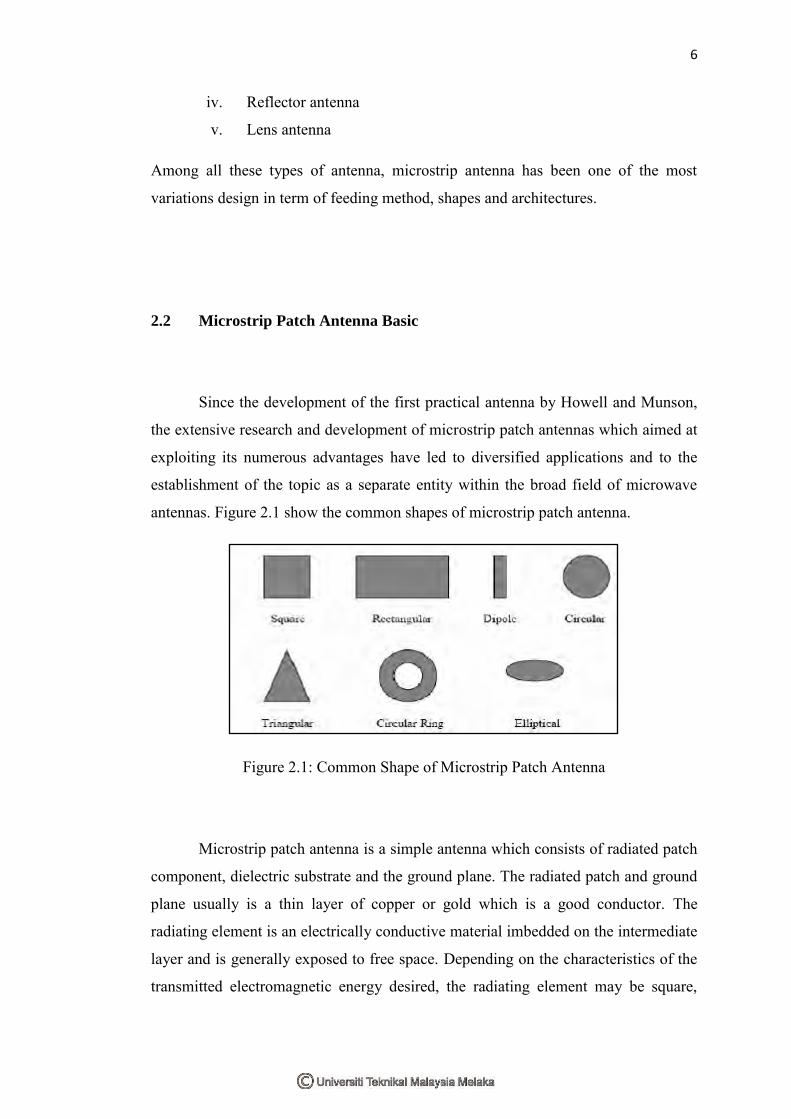
antennas. Figure 2.1 show the common shapes of microstrip patch antenna.
Figure 2.1: Common Shape of Microstrip Patch Antenna
Microstrip patch antenna is a simple antenna which consists of radiated patch
component, dielectric substrate and the ground plane. The radiated patch and ground
plane usually is a thin layer of copper or gold which is a good conductor. The
radiating element is an electrically conductive material imbedded on the intermediate
layer and is generally exposed to free space. Depending on the characteristics of the
transmitted electromagnetic energy desired, the radiating element may be square,

7
rectangular, triangular, or circular and is separated from the ground plane layer as
shown in figure 2.2.
Figure 2.2: Structure of Microstrip Patch Antenna
Each dielectric substrate has its own dielectric permittivity value. This value
is very important in designing antenna and also has great influence to the size of the
antenna. Besides, the thickness of substrate also can influence the antenna
performance. It can increase the bandwidth and efficiency if the antenna, but
unfortunately it will generate surface wave with low propagation that cause lost of
power. Microstrip antenna is a low profile antenna, conformable to planar and non-
planar surfaces, simple and inexpensive to manufacture. In term of wearable system,
the crumpling of fabric material is does not affect much on performance of the
microstrip patch antenna[3].
Microstrip patch antennas have several advantages compared to conventional
microwave antennas, and therefore many applications cover the broad frequency
range from 100MHz to 100GHz. A few principal advantages of microstrip patch
antennas compared to conventional microwave antennas are light weight, thin profile
configurations, robust nature, low fabrication cost, dual-frequency and dual-
polarization antennas can be easily made and can be easily integrated with
microwave integrated circuits. However, microstrip patch antenna also have some
limitations compared to conventional microwave antennas which is narrow
bandwidth, lower gain, lower power handling capability, excitations of surfaces

8
waves, and also difficult to achieve the purity of polarization. As the primary concern
of this project is it conformability, low cost and integration with microwave
integrated circuits, microstrip patch is chosen despite the inherent limitations
possessed by this technology.
2.3 Microstrip Patch Antenna Properties
Performance of an antenna can be described based on the definitions of
various parameters like return loss, radiation pattern, bandwidth, and polarization.
There are some parameters are interrelated and not at all of parameters need to be
specified for complete description of the antenna performance.
2.3.1 Radiation Pattern
Radiation pattern is defined as a mathematical function or a graphical
representation of the radiation properties of the antenna as a function of space
coordinates[2]. The radiation pattern usually is determined in the far-field region and
represented as a function of the directional coordinates. Antenna radiations consist of
several properties such as power flux density, radiation intensity, field strength, and
directivity phase or polarization. Patterns must be observed in the far field region as
it is considered by the independence of the relative angular distribution of the field
with varying distance consequently making the pattern is essentially independent of
distance.
An important parameter of the radiation pattern is the two (2D) or three
dimensional (3D) spatial distribution of radiated energy as a function of observed
position. There are two pattern in antenna radiation which is power pattern and

9
amplitude field pattern. Power pattern is define as a trace of the power received at a
constant radius while an amplitude field pattern is the trace of the variation of
electric or magnetic field along a constant radius. Most antennas have certain
symmetrical features, thus in reality, the most important patterns are the radiation
patterns in the two main planes: the E-plane and the H-plane. The E-plane is the
plane that the electric field E lies on, while the H-plane is the plane that the magnetic
field H is on. For the ideal current element case, the electric field is 𝐸𝜃 and the
magnetic field is 𝐻𝜑 , thus the E-plane pattern is the field 𝐸𝜃 measured as a function
of θ when the angle φ and the distance are fixed, while the H-plane pattern is the
field 𝐸𝜃 measured as a function of φ when the angle θ and the distance are fixed.
There are various part of a radiation pattern which is called as lobes. These
lobes can be sub classified into major or main, minor, side and back lobes. A
radiation lobe is portion of the radiation pattern bounded by regions of relatively
weak radiation intensity[2]. Radiation patterns may be plotted in a symmetrical three
dimensional (3D) polar patterns and linear two-dimensional pattern where the same
patterns characteristics are indicated. The plotted radiation patterns are as illustrated
in Figure 2.3.
Figure 2.3: (a) 3D and (b) 2D Antenna Radiation Pattern[2].