Module 7 (Lecture 24 to 28) RETAINING WALLS … · nptel - advanced foundation engineering-1 module...
17
NPTEL - ADVANCED FOUNDATION ENGINEERING-1 Module 7 (Lecture 24 to 28) RETAINING WALLS Topics 24.1 INTRODUCTION 24.2 GRAVITY AND CANTILEVER WALLS 24.3 PROPORTIONING RETAINING WALLS 24.4 APPLICATION OF LATERAL EARTH PRESSURE THEORIES TO DESIGN 24.5 STABILITY CHECKS Check for Overturning’ Check for Sliding Along the Base Check for Bearing Capacity Failure Example Factor of Safety Against Overturning Factor of Safety Against Sliding Factor of Safety Against Bearing Capacity Failure 25.1 OTHER TYPES OF POSSIBLE RETAINING WALL FAILURE 26.1 COMMENTS RELATING TO STABILITY 26.2 DRAINAGE FROM THE BACKFILL OF THE RETAINING WALL 26.3 PROVISION OF JOINTS IN RETAINING-WALL CONSTRUCTION
Transcript of Module 7 (Lecture 24 to 28) RETAINING WALLS … · nptel - advanced foundation engineering-1 module...
NPTEL - ADVANCED FOUNDATION ENGINEERING-1
Module 7
(Lecture 24 to 28)
RETAINING WALLS
Topics
24.1 INTRODUCTION 24.2 GRAVITY AND CANTILEVER WALLS 24.3 PROPORTIONING RETAINING WALLS 24.4 APPLICATION OF LATERAL EARTH PRESSURE
THEORIES TO DESIGN 24.5 STABILITY CHECKS
Check for Overturning’ Check for Sliding Along the Base
Check for Bearing Capacity Failure Example Factor of Safety Against Overturning Factor of Safety Against Sliding Factor of Safety Against Bearing Capacity Failure
25.1 OTHER TYPES OF POSSIBLE RETAINING WALL FAILURE
26.1 COMMENTS RELATING TO STABILITY 26.2 DRAINAGE FROM THE BACKFILL OF THE
RETAINING WALL 26.3 PROVISION OF JOINTS IN RETAINING-WALL
CONSTRUCTION

NPTEL - ADVANCED FOUNDATION ENGINEERING-1
26.4 GRAVITY RETAINING-WALL DESIGN FOR
EARTHQUAKE CONDITIONS
26.5 MECHANICALLY STABILIZED RETAINING
WALLS
26.6 GENERAL DESIGN CONSIDERATIONS
27.1 RETAINING WALLS WITH METALLIC STRIP REINFORCEMENT
Calculation of Active Horizontal and vertical Pressure Tie Force Factor of Safety Against Tie Failure Total Length of Tie
27.2 STEP-BY-STEP DESIGN PROCEDURE (METALLIC STRIP REINFORCEMENT
Internal Stability External Stability Internal Stability Check Tie thickness Tie length External Stability Check Check for overturning Check for sliding Check for bearing capacity
28.1 RETAINING WALLS WITH METALLIC STRIP
REINFORCEMENT 28.2 Calculation of Active Horizontal and vertical Pressure Tie Force

NPTEL - ADVANCED FOUNDATION ENGINEERING-1
Factor of Safety Against Tie Failure Total Length of Tie
28.3 STEP-BY-STEP DESIGN PROCEDURE (METALLIC STRIP REINFORCEMENT
General: Internal Stability: Internal Stability Check Check for overturning: Check for sliding Check for bearing capacity
PROBLEMS
REFERENCE

NPTEL - ADVANCED FOUNDATION ENGINEERING-1
Module 7
(Lecture 24)
RETAINING WALLS
Topics
1.1 INTRODUCTION 1.2 GRAVITY AND CANTILEVER WALLS
PROPORTIONING RETAINING WALLS
1.3 APPLICATION OF LATERAL EARTH PRESSURE THEORIES TO DESIGN
1.4 STABILITY CHECKS
Check for Overturning’ Check for Sliding Along the Base
INTRODUCTION
In chapter 6 you were introduced to various types of lateral earth pressure. Those theories will be used in this chapter to design various types of retaining walls. In general, retaining walls can be divided into two major categories: (a) conventional retaining walls, and (b) mechanically stabilized earth walls.
Conventional retaining walls can generally be classified as
1. Gravity retaining walls 2. Semigravity retaining walls 3. Cantilever retaining walls 4. Counterfort retaining walls

NPTEL - ADVANCED FOUNDATION ENGINEERING-1
Gravity retaining walls (figure 7.1a) are constructed with plain concrete or stone masonry. They depend on their own weight and any soil resting on the masonry for stability. This type of construction is not economical for high walls.
Figure 7.1 Types of retaining wall
In many cases, a small amount of steel may be used for the construction of gravity walls, thereby minimizing the size of wall sections. Such walls are generally referred to as semigravity walls (figure 7.1b).
Cantilever retaining walls (figure 7.1c) are made of reinforced concrete that consists of a thin stem and a base slab. This type of wall is economical to a height of about 25 ft (8 m).
Counterfort retaining walls (figure 7.1d) are similar to cantilever walls. At regular intervals, however, they have thin vertical concrete slabs known as counterforts that tie the wall and the base slab together. The purpose of the counterforts is to reduce the shear and the bending moments.
To design retaining walls properly, an engineer must know the basic soil parameters-that is, the unit weight, angle of friction, and cohesion-for the soil retained behind the wall and the soil below the base slab. Knowing the properties of the soil behind the wall enables the engineer to determine the lateral pressure distribution that has to be designed for.
There are two phases in the design of conventional retaining walls. First, with the lateral earth pressure known, the structure as a whole is checked for stability. That includes checking for possible overturning, sliding, and bearing capacity failures.

NPTEL - ADVANCED FOUNDATION ENGINEERING-1
Second, each component of the structure is checked for adequate strength, and the steel reinforcement of each component is determined.
This chapter presents the procedures for determining retaining wall stability. Checks for adequate strength of each component of the structures can be found in any textbook on reinforced concrete.
Mechanically stabilized retaining walls have their backfills stabilized by inclusion of reinforcing elements such as metal strips, bars, welded wire mats, geotextiles, and geogrids. These walls are relatively flexible and can sustain large horizontal and vertical displacement without much damage.
In this chapter the gravity and cantilever retaining walls will be described first, followed by mechanically stabilized walls with metal strips, geotextiles, and geogrids reinforced backfills.
GRAVITY AND CANTILEVER WALLS
PROPORTIONING RETAINING WALLS
When designing retaining walls, an engineer must assume some of the dimensions, called proportioning, which allows the engineer to check trial sections for stability. If the stability checks yield undesirable results, the sections can be changed and rechecked. Figure 7. 2 shows the general proportions of various retaining walls components that can be used for initial checks.
Figure 7.2 Approximate dimensions for various components of retaining wall for initial stability checks: (a) gravity wall; (b) cantilever wall [note: minimum dimension of 𝐷𝐷 is 2 ft (≈ 0.6 m)]

NPTEL - ADVANCED FOUNDATION ENGINEERING-1
Note that the top of the stem of any retaining wall should not be less than about 12 in. (≈0.3 m) for proper placement of concrete. The depth, D, to the bottom of the base slab should be a minimum of 2 ft (≈ 0.6 m). However, the bottom of the base slab should be positioned below the seasonal frost line.
For counterfort retaining walls, the general proportion of the stem and the base slab is the same as for cantilever walls. However, the counterfort slabs may be about 12 in. (≈0.3 m) thick and spaced at center-to-center distances of 0.3𝐻𝐻 to 0.7 𝐻𝐻.
APPLICATION OF LATERAL EARTH PRESSURE THEORIES TO DESIGN
The fundamental theories for calculating lateral earth pressure have been presented in chapter 6. To use these theories in design, an engineer must make several simple assumptions. In the case of cantilever walls, use of the Rankine earth pressure theory for stability checks involves drawing a vertical line 𝐴𝐴𝐴𝐴 through point A, as shown in figure 7. 3a, (which is located at the edge of the heel of the base slab. The Rankine active condition is assumed to exist along the vertical plane 𝐴𝐴𝐴𝐴. Rankine active earth pressure equations may then be used to calculate the lateral pressure on the face 𝐴𝐴𝐴𝐴. In the analysis of stability for the wall, the force 𝑃𝑃𝑎𝑎(Rankine ), the weight of soil above the heel, 𝑊𝑊𝑠𝑠, and the weight of the concrete, 𝑊𝑊𝑐𝑐 , all should be taken into consideration. The assumption for the development of Rankine active pressure along the soil face 𝐴𝐴𝐴𝐴 is theoretically concrete if the shear zone bounded by the line 𝐴𝐴𝐴𝐴 is not obstructed by the stem of the wall. The angle, 𝜂𝜂, that the line 𝐴𝐴𝐴𝐴 makes with the vertical is
𝜂𝜂 = 45 + 𝛼𝛼2− 𝜙𝜙
2− sin−1 �sin 𝛼𝛼
sin 𝜙𝜙� [7.1]
Figure 7.3 Assumption for the determination of lateral earth pressure: (a) cantilever wall; (b) and (c) gravity wall

NPTEL - ADVANCED FOUNDATION ENGINEERING-1
Figure 7. 3 Continued
A similar type of analysis may be used for gravity walls, as shown in figure 7. 3b. However, Coulomb’s theory also may be used, as shown in figure 7. 3c. If Coulomb’s active pressure theory is used, the only forces to be considered are 𝑃𝑃𝑎𝑎(Coulomb ) and the weight of the wall, 𝑊𝑊𝑐𝑐 .
If Coulomb’s earth pressure theory is used, it will be necessary to know the range of the wall friction angle 𝛿𝛿 with various types of backfill material. Following are some ranges of wall friction angle for masonry or mass concrete walls:
Backfill material Range of 𝛿𝛿(deg)
Gravel 27-30
Coarse sand 20-28
Fine sand 15-25
Stiff clay 15-20
NPTEL - ADVANCED FOUNDATION ENGINEERING-1
Silty clay 12-16
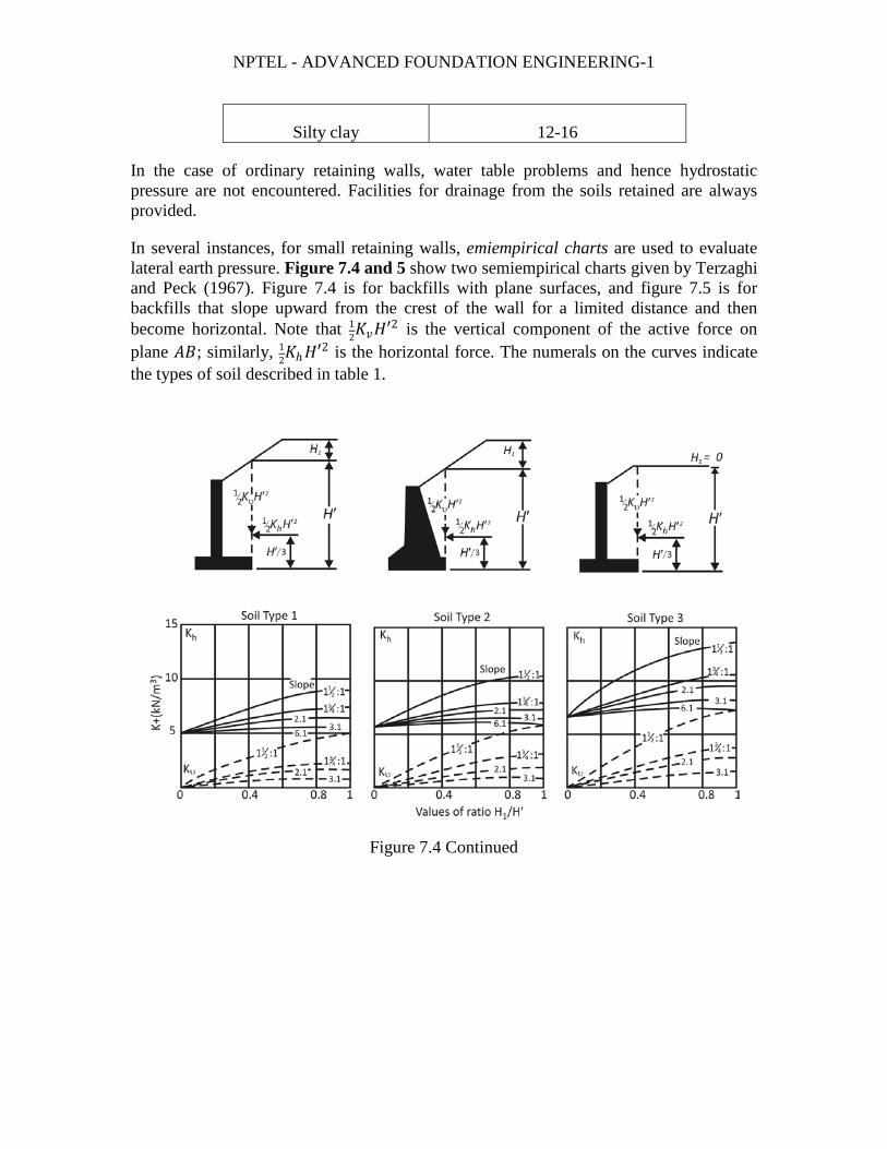
In the case of ordinary retaining walls, water table problems and hence hydrostatic pressure are not encountered. Facilities for drainage from the soils retained are always provided.
In several instances, for small retaining walls, emiempirical charts are used to evaluate lateral earth pressure. Figure 7.4 and 5 show two semiempirical charts given by Terzaghi and Peck (1967). Figure 7.4 is for backfills with plane surfaces, and figure 7.5 is for backfills that slope upward from the crest of the wall for a limited distance and then become horizontal. Note that 1
2𝐾𝐾𝑣𝑣𝐻𝐻′2 is the vertical component of the active force on
plane 𝐴𝐴𝐴𝐴; similarly, 12𝐾𝐾ℎ𝐻𝐻′
2 is the horizontal force. The numerals on the curves indicate the types of soil described in table 1.
Figure 7.4 Continued

NPTEL - ADVANCED FOUNDATION ENGINEERING-1
Figure 7.5 Chart for estimating pressure of backfill against retaining walls supporting backfills with surface that slopes upward from crest of wall for limited distance and then becomes horizontal (after Soil Mechanics in Engineering Practice, Second Edition, by K. Terzaghi and R. B. Peck. Copyright 1967 by John Wiley and Sons. Reprinted with permission) (note: 1 kN/m3 = 6.361 lb/ft3)
Chart for estimating pressure of backfill against retaining walls supporting backfills with surface that slopes upward from crest of wall for limited distance and then becomes horizontal (after Soil Mechanics in Engineering Practice, Second Edition, by K. Terzaghi and R. B. Peck. Copyright 1967 by John Wiley and Sons. Reprinted with permission) (note: 1 kN/m3 = 6.361 lb/ft3)
STABILITY CHECKS
To check the stability of a retaining wall, the following steps are necessary:
1. Check for overturning about its toe 2. Check for sliding along its base 3. Check for bearing capacity failure of the base 4. Check for settlement 5. Check for overall stability
This section describes the procedure for checking for overturning and sliding and bearing capacity failure. The principles of investigation for settlement were covered in chapter 4 and will not be repeated here. Some problems regarding the overall stability of retaining walls are discussed in section 5.

NPTEL - ADVANCED FOUNDATION ENGINEERING-1
Check for Overturning’
Figure 7. 6 shows the forces acting on a cantilever and a gravity retaining wall, based on the assumption that the Rankine active pressure is acting along a vertical plane 𝐴𝐴𝐴𝐴 drawn through the heel. 𝑃𝑃𝑝𝑝 is the Rankine passive pressure; recall that its magnitude is
𝑃𝑃𝑝𝑝 = 12𝐾𝐾𝑝𝑝𝛾𝛾2𝐷𝐷2 + 2𝑐𝑐2�𝐾𝐾𝑝𝑝𝐷𝐷 (Chapter 6 equation 58)
Figure 7.6 Check for overturning: assume that Rankine pressure is valid:
Table 1 types of Backfill for Retaining Walls

NPTEL - ADVANCED FOUNDATION ENGINEERING-1
1. Coarse-grained soil without admixture of fine soil particles, very permeable
(clean sand or gravel). 2. Coarse-grained soil of low permeability due to admixture of particles of silt size. 3. Residual soil with stones, fine silty sand, and granular materials with conspicuous
clay content. 4. Very soft or soft clay, organic silts, or silty clay. 5. Medium or stiff clay, deposited in chunks and protected in such a way that a
negligible amount of water enters the spaces between the chunks during floods or heavy rains. If this condition of protection cannot be satisfied, the clay should not be used as backfill material. With increasing stiffness of the clay, danger to the wall due to infiltration of water increases rapidly.
From Soil Mechanics in Engineering Practice, Second Edition, by K. Terzaghi and R. B. Peck. Copyright 1967 by John Wiley and Sons. Reprinted with permission.
Where
𝛾𝛾2 = unit weight of soil in front of the heel and under the base slab
𝐾𝐾𝑝𝑝 = Rankine passive earth pressure coefficient = tan2(45 + 𝜙𝜙2/2)
𝑐𝑐2,𝜙𝜙2 = cohesion and soil friction angle, respectively
The factor of safety against overturning about the toe-that is, about point C in figure 7. 6-may be expressed as
𝐹𝐹𝐹𝐹(overturning ) = Σ 𝑀𝑀𝑅𝑅Σ 𝑀𝑀𝑂𝑂
[7.2]
Where
Σ 𝑀𝑀𝑂𝑂 = sum of the moments of forces tending to overturn about point 𝐴𝐴
Σ 𝑀𝑀𝑅𝑅 = sum of the moments of forces tending to resist overturning about point 𝐴𝐴
The overturning moment is
Σ 𝑀𝑀𝑂𝑂 = 𝑃𝑃ℎ �𝐻𝐻′3� [7.3]
Where 𝑃𝑃ℎ = 𝑃𝑃𝑎𝑎 cos𝛼𝛼
For calculation of the resisting moment, Σ 𝑀𝑀𝑅𝑅 (neglecting𝑃𝑃𝑃𝑃), a table (such as table 2) can he prepared. The weight of the soil above the heel and the weight of the concrete (or masonry) are both forces that contribute to the resisting moment. Note that the force 𝑃𝑃𝑣𝑣

NPTEL - ADVANCED FOUNDATION ENGINEERING-1
also contributes to the resisting moment. 𝑃𝑃𝑣𝑣 is the vertical component of the active force 𝑃𝑃𝑎𝑎 , or
𝑃𝑃𝑣𝑣 = 𝑃𝑃𝑎𝑎 sin𝛼𝛼 [7.4]
The moment of the force 𝑃𝑃𝑣𝑣 about C is
𝑀𝑀𝑣𝑣 = 𝑃𝑃𝑣𝑣𝐴𝐴 = 𝑃𝑃𝑎𝑎 sin𝛼𝛼 𝐴𝐴 [7.5]
Where
𝐴𝐴 = width of the base slab
Table 2 Procedure for Calculation of Σ 𝑀𝑀𝑅𝑅
Section (1)
Area (2)
Weight/unit length of wall (3)
Moment arm measured from C (4)
Moment about C (5)
1 𝐴𝐴1 𝑊𝑊1 = 𝛾𝛾1 × 𝐴𝐴1 𝑋𝑋1 𝑀𝑀1
2 𝐴𝐴2 𝑊𝑊2 = 𝛾𝛾2 × 𝐴𝐴2 𝑋𝑋2 𝑀𝑀2
3 𝐴𝐴3 𝑊𝑊3 = 𝛾𝛾𝑐𝑐 × 𝐴𝐴3 𝑋𝑋3 𝑀𝑀3
4 𝐴𝐴4 𝑊𝑊4 = 𝛾𝛾𝑐𝑐 × 𝐴𝐴4 𝑋𝑋4 𝑀𝑀4
5 𝐴𝐴5 𝑊𝑊5 = 𝛾𝛾𝑐𝑐 × 𝐴𝐴5 𝑋𝑋5 𝑀𝑀5
6 𝐴𝐴6 𝑊𝑊6 = 𝛾𝛾𝑐𝑐 × 𝐴𝐴6 𝑋𝑋6 𝑀𝑀6
𝑃𝑃𝑣𝑣 𝐴𝐴 𝑀𝑀𝑣𝑣
Σ 𝑉𝑉 Σ 𝑀𝑀𝑅𝑅
Note: 𝛾𝛾1 = unit weight of backfill
𝛾𝛾2 = unit weight of concrete
Once Σ 𝑀𝑀𝑅𝑅 is known, the factor of safety can be calculated as
𝐹𝐹𝐹𝐹(overturning ) = 𝑀𝑀1+𝑀𝑀2+𝑀𝑀3+𝑀𝑀4+𝑀𝑀5+𝑀𝑀6 𝑃𝑃𝑎𝑎 cos 𝛼𝛼(𝐻𝐻′ /3)−𝑀𝑀𝑣𝑣
[7.6]

NPTEL - ADVANCED FOUNDATION ENGINEERING-1
Check for Sliding Along the Base
The factor of safety against sliding may be expressed by the equation
𝐹𝐹𝐹𝐹(sliding ) = Σ 𝐹𝐹𝑅𝑅Σ 𝐹𝐹𝑑𝑑
[7.7]
Where
Σ 𝐹𝐹𝑅𝑅 = sum of the horizontal resisting forces
Σ 𝐹𝐹𝑑𝑑 = sum of the horizontal driving forces
Figure 7. 7 indicates that the shear strength of the soil immediately below the base slab may be represented as
𝑠𝑠 = 𝜎𝜎 tan 𝛿𝛿 + 𝑐𝑐𝑎𝑎
Where
𝛿𝛿 = angle of friction between the soil and the base slab
𝑐𝑐𝑎𝑎 = adhesion between the soil and the base slab
Figure 7.7 Check for sliding along the base

NPTEL - ADVANCED FOUNDATION ENGINEERING-1
Thus the maximum resisting force that can be derived from the soil per unit length of the wall along the bottom of the base slab is
𝑅𝑅′ = 𝑠𝑠(area of cross section) = 𝑠𝑠(𝐴𝐴 × 1) = 𝐴𝐴𝜎𝜎 tan 𝛿𝛿 + 𝐴𝐴𝑐𝑐𝑎𝑎
However,
𝐴𝐴𝜎𝜎 = sum of the vertical force = Σ 𝑉𝑉 (see table 2)
So
𝑅𝑅′ = (Σ 𝑉𝑉) tan 𝛿𝛿 + 𝐴𝐴𝑐𝑐𝑎𝑎 + 𝑃𝑃𝑝𝑝 [7.8]
The only horizontal force that will tend to cause the wall to slide (driving force) is the horizontal component of the active force 𝑃𝑃𝑎𝑎 , so
Σ 𝐹𝐹𝑑𝑑 = 𝑃𝑃𝑎𝑎 cos𝛼𝛼 [7.9]
Combings equations (7, 8, and 9) yields
𝐹𝐹𝐹𝐹(sliding ) =(Σ 𝑉𝑉) tan 𝛿𝛿+𝐴𝐴𝑐𝑐𝑎𝑎+𝑃𝑃𝑝𝑝
𝑃𝑃𝑎𝑎 cos 𝛼𝛼 [7.10]
A minimum factor of safety of 1.5 against sliding is generally required.
In many cases, the passive force 𝑃𝑃𝑝𝑝 is ignored for calculation of the factor of safety with respect to sliding. In general, we can write 𝛿𝛿 = 𝑘𝑘1𝜙𝜙2 and 𝑐𝑐𝑎𝑎 = 𝑘𝑘2𝑐𝑐2. In most cases, 𝑘𝑘1 and 𝑘𝑘2 are in the range of 1
2 to 23. Thus
𝐹𝐹𝐹𝐹(sliding ) =(Σ 𝑉𝑉) tan (𝑘𝑘1𝜙𝜙2)+𝐴𝐴𝑘𝑘2𝑐𝑐2+𝑃𝑃𝑝𝑝
𝑃𝑃𝑎𝑎 cos 𝛼𝛼 [7.11]
In some instances, certain walls may not yield a desired factor of safety of 1.5. To increase their resistance to sliding, a base key may be used. Base keys are illustrated by broken lines in figure 7. 7. It indicates that the passive force at the toe without the key is
𝑃𝑃𝑝𝑝 = 12𝛾𝛾2𝐷𝐷2𝐾𝐾𝑝𝑝 + 2𝑐𝑐2𝐷𝐷�𝐾𝐾𝑝𝑝
However, it a key is included, the passive force per unit length of the wall becomes
𝑃𝑃𝑝𝑝 = 12𝛾𝛾2𝐷𝐷
12𝐾𝐾𝑝𝑝 + 2𝑐𝑐2𝐷𝐷1�𝐾𝐾𝑝𝑝
Where
𝐾𝐾𝑝𝑝 = tan2(45 + 𝜙𝜙2/2)

NPTEL - ADVANCED FOUNDATION ENGINEERING-1
Because 𝐷𝐷1 > 𝐷𝐷, a key obviously will help increase the passive resistance at the toe and hence the factor of safety against sliding. Usually the base key is constructed below the stem and some main steel is run into the key.
Another possible way to increase the value of 𝐹𝐹𝐹𝐹(sliding ) is to consider reducing the value of 𝑃𝑃𝑎𝑎 [see equation (11)]. One possible way to do so is to use the method, developed by Elman and Terry (1988). The discussion here is limited to the case in which the retaining wall has to horizontal granular backfill (figure 7. 8). In figure 7. 8, the active force, 𝑃𝑃𝑎𝑎 , is horizontal (𝛼𝛼 = 0) so that
Figure 7.8 Retaining wall with sloped heel
𝑃𝑃𝑎𝑎 cos𝛼𝛼 = 𝑃𝑃ℎ = 𝑃𝑃𝑎𝑎
And
𝑃𝑃𝑎𝑎 sin𝛼𝛼 = 𝑃𝑃𝑣𝑣 = 0
However,
𝑃𝑃𝑎𝑎 = 𝑃𝑃𝑎𝑎(1) + 𝑃𝑃𝑎𝑎(2) [7.12]
The magnitudes of 𝑃𝑃𝑎𝑎(2) can be reduced if the heel of the retaining wall is sloped as shown in figure 7. 8b. For this case,
𝑃𝑃𝑎𝑎 = 𝑃𝑃𝑎𝑎(1) + 𝐴𝐴𝑃𝑃𝑎𝑎(2) [7.13]
The magnitude of A, as shown in figure 7. 9, is valid for 𝛼𝛼′ = 45°. However, note that in figure 7. 8a

NPTEL - ADVANCED FOUNDATION ENGINEERING-1
Figure 7.9 Variation of A with friction angle of backfill [equation (14)]
𝑃𝑃𝑎𝑎(1) = 12𝛾𝛾1𝐾𝐾𝑎𝑎(𝐻𝐻′ − 𝐷𝐷′)2
And
𝑃𝑃𝑎𝑎 = 12𝛾𝛾1𝐾𝐾𝑎𝑎𝐻𝐻′2
Hence
𝑃𝑃𝑎𝑎(2) = 12𝛾𝛾1𝐾𝐾𝑎𝑎[𝐻𝐻′2 − (𝐻𝐻′ − 𝐷𝐷′)2]
So, for the active pressure diagram shown in figure 7. 8b,
𝑃𝑃𝑎𝑎 = 12𝛾𝛾1𝐾𝐾𝑎𝑎(𝐻𝐻′ − 𝐷𝐷′)2 + 𝐴𝐴
2𝛾𝛾1𝐾𝐾𝑎𝑎[𝐻𝐻′2 − (𝐻𝐻′ − 𝐷𝐷′)2] [7.14]
Sloping the heel of a retaining wall can thus be extremely helpful in some cases.