MODULE 5: Ground improvement of soils prone to · PDF file4 PerformanCe requIrements 16 ......
62
Earthquake geotechnical engineering practice MODULE 5: Ground improvement of soils prone to liquefaction
-
Upload
truongthuan -
Category
Documents
-
view
222 -
download
4
Transcript of MODULE 5: Ground improvement of soils prone to · PDF file4 PerformanCe requIrements 16 ......
Earthquake geotechnical engineering practice
MODULE 5: Ground improvement of soils prone to liquefaction

DATE: junE 2017
MoDulE 5: Ground ImprovEmEnt of SoIlS pronE to lIquEfactIon
paGE b
2Acknowledgements
lead Authors
• campbell Keepa – opus International consultants ltd
• dr alexei murashev – opus International ltd
Contributing Authors
• prof r orense – university of auckland
• prof misko cubrinovski – university of canterbury
• dr Kevin j mcmanus – mcmanus Geotech ltd
• charlie price – mWH Global – StantEc, nZGS chair
• john Scott – ministry of business, Innovation & Employment
• dr Gilles Seve – ministry of business, Innovation & Employment
• mike Stannard – ministry of business, Innovation & Employment
• nick traylen – Geotech consulting ltd
• rick Wentz – Wentz pacific ltd
Reviewers
• phil clayton – beca Infrastructure
• tony fairclough – tonkin & taylor
• nick Wharmby – march construction ltd
• Stuart palmer – tonkin & taylor
International reviewers
• prof jonathon bray – university of california, berkeley
• dr Geoffrey martin – professor Emeritus, university of Southern california
• prof Susumu Yasuda – tokyo denki university, japan
Funding organisations
• ministry of business, Innovation & Employment (mbIE)
• Earthquake commision (Eqc)
• new Zealand Geotechnical Society (nZGS)
Document status
ISbn (print) 978-1-98-851736-0 ISbn (online) 978-1-98-851735-3
new Zealand Geotechnical Society (nZGS) and ministry of business, Innovation & Employment (mbIE) Earthquake Geotechnical Engineering practice in new Zealand
Issue date may 2017 amended june 2017
this document is issued as guidance under section 175 of the building act 2004 to assist parties to comply with their obligations under the building act 2004.
It is not mandatory to follow the guidance, but if followed:
• it does not relieve any person of the obligation to consider any matter to which that information relates according to the circumstances of the particular case
• the building consent authority may have regard to the guidance, but is not bound to accept the guidance as demonstrating compliance with the building code
• users should consider taking appropriate professional advice prior to entering into a construction contract which incorporates all or parts of this document.
While the ministry of business, Innovation and Employment and the new Zealand Geotechnical Society have taken care in preparing this document, it is only a guide and, if used, does not relieve any person of the obligation to consider any matter to which that information relates, according to the circumstances of the case. all users should satisfy themselves as to the applicability of the content and should not act on the basis of any matter contained in this document without considering, and if necessary, taking appropriate professional advice.
the document may be updated from time to time and the latest version is available from the ministry’s website: www.building.govt.nz or the new Zealand Geotechnical Society’s website: www.nzgs.org/publications/guidelines.htm.
Disclaimer
the material contained in this document is intended as a guideline only.
all readers should satisfy themselves as to the applicability of the recommendations made and should not act on the basis of any matter contained in this document without considering, and if necessary taking appropriate professional advice on, the particular circumstances to which they wish it to be applied.
the publishers, editor and contributors expressly disclaim all and any liability to any person in respect of anything to be done or omitted by any such person in reliance upon the whole or any part of the contents of this document.
Important notice
this document is preliminary and the contents should be treated as draft guidelines. Submissions by the geotechnical community to the Society are encouraged, after which a further review will be undertaken. the contents may be subject to further changes, additions, and deletions.
© Copyright
the copyright owner authorises reproduction of this work, in whole or in part, so long as no charge is made for the supply of copies, and the integrity and attribution of the contributors and publishers of the document is not interfered with in any way.

DATE: junE 2017
MoDulE 5: Ground ImprovEmEnt of SoIlS pronE to lIquEfactIon
paGE 1
5 contents
Contents
PrefaCe 4
1 IntroduCtIon 5
1.1 objective 5
1.2 Scope 6
2 sIte and LIquefaCtIon ConsIderatIons 7
2.1 Site characterisation 7
2.2 liquefaction considerations 8
liquefaction evaluation 8
Effects of liquefaction on buildings 8
3 Ground ImProvement PrInCIPLes 9
3.1 methods of ground improvement 9
replacement 10
densification 10
Solidification 10
reinforcement 10
drainage 10
3.2 Seismic response of buildings supported on improved ground 11
Effects on structural response 11
deformation modes 11
4 PerformanCe requIrements 16
4.1 regulatory requirements 16
4.2 Ground improvement performance objectives 17
5 Ground ImProvement desIGn 18
5.1 design process 18
5.2 Selection of ground improvement method 19
5.3 Extent of ground improvement below buildings with shallow footings 19
depth of treatment 19
lateral extent of treatment 21
mitigation of lateral spreading effects on buildings 21
5.4 drainage blankets 22
5.5 other considerations 23

DATE: junE 2017
MoDulE 5: Ground ImprovEmEnt of SoIlS pronE to lIquEfactIon
paGE 2
5contents
6 rePLaCement methods 24
6.1 outline 24
6.2 Site conditions suitable for replacement 24
6.3 design considerations 24
7 densIfICatIon methods 25
7.1 outline 25
7.2 Site conditions suitable for densification 26
7.3 design considerations 27
7.4 design verification 28
7.5 dynamic compaction 29
7.6 vibro-compaction 31
7.7 Stone columns 33
7.8 compaction piles 34
7.9 compaction grouting 34
7.10 resin injection 35
8 soLIdIfICatIon methods 37
8.1 outline 37
8.2 techniques for solidification 37
8.3 Site conditions suitable for solidification 38
8.4 design considerations 38
8.5 design verification and quality control 39
8.6 Soil mixing 39
8.7 jet grouting 40
8.8 permeation grouting 40
9 reInforCement methods 41
9.1 outline 41
9.2 techniques for reinforcement 42
9.3 Site conditions suitable for reinforcement 42
9.4 design considerations 42
9.5 design verification 43
9.6 lattice reinforcement 43
9.7 Stiff columnar reinforcement grids 44

DATE: junE 2017
MoDulE 5: Ground ImprovEmEnt of SoIlS pronE to lIquEfactIon
paGE 3
5 contents
10 draInaGe methods 45
10.1 outline 45
10.2 permanent dewatering 46
10.3 vertical drains 47
11 Ground ImProvement for resIdentIaL ConstruCtIon 48
11.1 applicability 49
11.2 design philosophy 49
11.3 liquefaction mitigation strategies 50
11.4 Ground improvement mechanisms 50
11.5 Selection criteria 53
11.6 Specification, construction and quality control 53
12 ProCurement for desIGn and ConstruCtIon 54
13 BIBLIoGraPhy 55
DATE: junE 2017
MoDulE 5: Ground ImprovEmEnt of SoIlS pronE to lIquEfactIon
paGE 4
5preface
PrefaCethis document is part of a series of guidance modules developed jointly by the ministry of business, Innovation & Employment (mbIE) and the new Zealand Geotechnical Society (nZGS).
the guidance series along with an education programme aims to lift the level and improve consistency of earthquake geotechnical engineering practice in new Zealand, to address lessons from the canterbury earthquake sequence and canterbury Earthquakes royal commission recommendations. It is aimed at experienced geotechnical professionals, bringing up to date international research and practice.
this document should be read in conjunction with the other modules published to date in the series:
• module 1: overview of the Guidelines
• module 2: Geotechnical investigations for earthquake engineering
• module 3: Identification, assessment and mitigation of liquefaction hazards
• module 4: Earthquake resistant foundation design
• module 5a: Specification of ground improvement for residential properties in the canterbury region
• module 6: Earthquake resistant retaining wall design.
online training material in support of the series is available on the mbIE and nZGS websites: www.building.govt.nz and www.nzgs.org.
this module covers the design of ground improvement and supports the canterbury Earthquakes royal commission recommendations to prepare national guidelines specifying design procedures for ground improvement, to provide more uniformity in approach and outcomes.
this ground improvement module is supported by module 5a of the series, a specification dedicated to ground improvement for residential properties in the canterbury region. Ground improvement options and design for residential properties have also been addressed in Section 15.3 and appendix c of the mbIE document Repairing and rebuilding houses affected by the Canterbury earthquakes. although these two latter documents were written with the canterbury recovery in mind, their usefulness as guides for other liquefaction prone areas within new Zealand is recognised, with appropriate modifications being made to suit local conditions. module 5 addresses this issue.
We would encourage you to make yourselves familiar with the guidance and apply it appropriately in practice.
Charlie Price Mike Stannard chair chief Engineer new Zealand ministry of business, Geotechnical Society Innovation & Employment
DATE: junE 2017
MoDulE 5: Ground ImprovEmEnt of SoIlS pronE to lIquEfactIon
paGE 5
5 introduction
1 IntroduCtIon
1.1 objective
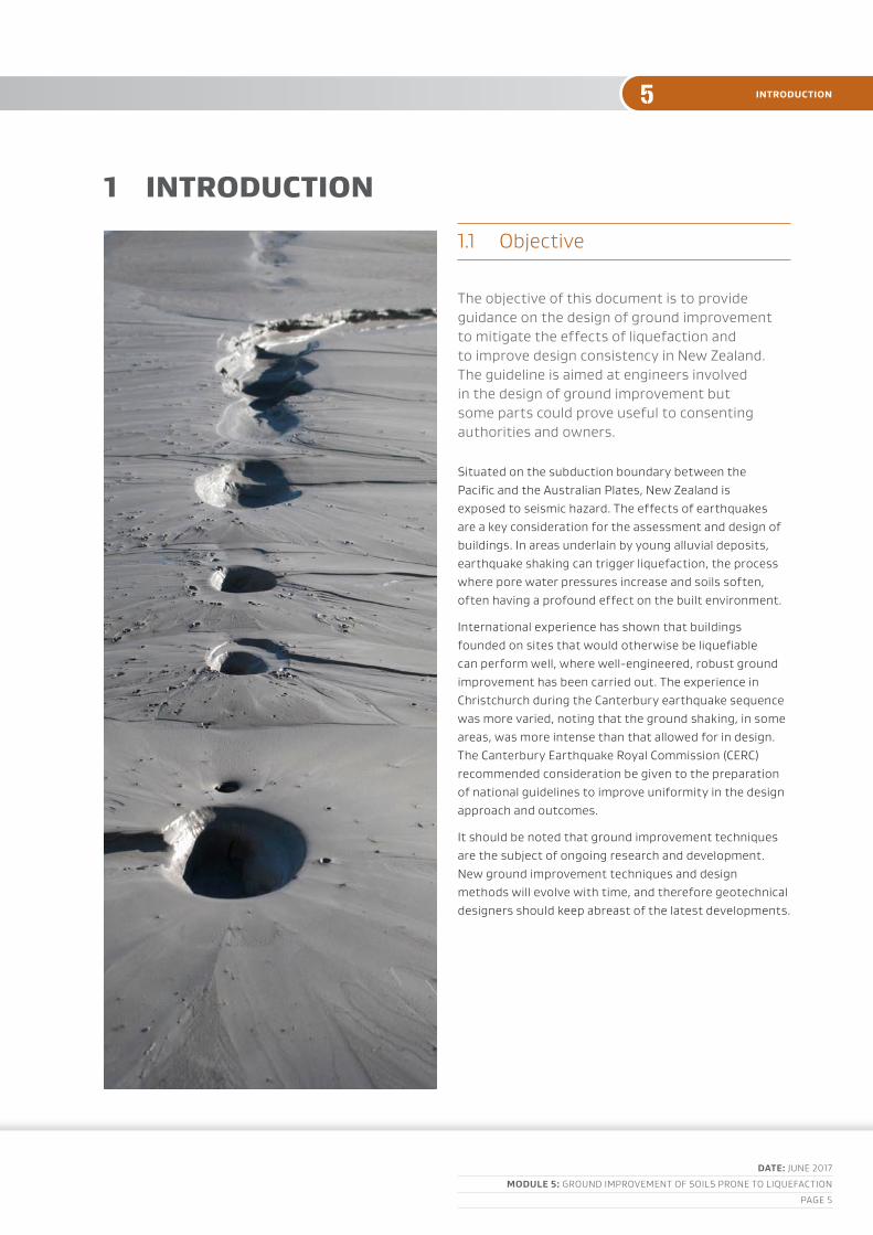
the objective of this document is to provide guidance on the design of ground improvement to mitigate the effects of liquefaction and to improve design consistency in new Zealand. the guideline is aimed at engineers involved in the design of ground improvement but some parts could prove useful to consenting authorities and owners.
Situated on the subduction boundary between the pacific and the australian plates, new Zealand is exposed to seismic hazard. the effects of earthquakes are a key consideration for the assessment and design of buildings. In areas underlain by young alluvial deposits, earthquake shaking can trigger liquefaction, the process where pore water pressures increase and soils soften, often having a profound effect on the built environment.
International experience has shown that buildings founded on sites that would otherwise be liquefiable can perform well, where well-engineered, robust ground improvement has been carried out. the experience in christchurch during the canterbury earthquake sequence was more varied, noting that the ground shaking, in some areas, was more intense than that allowed for in design. the canterbury Earthquake royal commission (cErc) recommended consideration be given to the preparation of national guidelines to improve uniformity in the design approach and outcomes.
It should be noted that ground improvement techniques are the subject of ongoing research and development. new ground improvement techniques and design methods will evolve with time, and therefore geotechnical designers should keep abreast of the latest developments.

DATE: junE 2017
MoDulE 5: Ground ImprovEmEnt of SoIlS pronE to lIquEfactIon
paGE 6
5introduction
1.2 Scope
this document identifies the key issues that need to be addressed in the design and construction of ground improvement to mitigate the effects of liquefaction, cyclic softening and lateral spreading effects on buildings and provides a framework for resolving these issues through design and construction. the objective is to provide concise, practical advice and simplified procedures for the design of ground improvement by qualified, experienced engineers based on the latest research and observations of the performance of ground improvement in earthquakes in new Zealand and internationally.
a wide range of ground improvement techniques are available to mitigate the effects of liquefaction and many of these are briefly described including techniques that have not been used extensively in new Zealand to date. there is no attempt to provide a comprehensive discussion of all available liquefaction countermeasures in this guideline; rather, only commonly used methods in new Zealand are outlined in detail. a bibliography is provided that gives greater depth on specific topics and aspects of ground improvement and practitioners and constructors are encouraged to read these where relevant. useful general references for the assessment and design of ground improvement to mitigate liquefaction include:
• Elias et al, 2006 Ground improvement methods, fHWa-nHI-06-19 and fHWa-nHI-06-020
• jie Han, 2015 principles and practices of ground improvement
• japanese Geotechnical Society 1998, remedial measures against liquefaction
• Kirsch and bell, 2012, Ground improvement.
because ground improvement technologies change rapidly and as new techniques are developed and existing techniques are refined and tested by actual earthquakes, the relevant geotechnical literature should be periodically reviewed.
the setting of seismic performance criteria for the building, the investigation and characterisation of a site, the evaluation of the liquefaction and lateral spreading hazard and design of foundation systems are discussed briefly here. more detailed discussion on these topics is presented in modules 1 to 4. these modules contain advice that is important to the successful design and construction of any ground improvement system and should be read in conjunction with this module. module 5a provides specifications for ground improvement for residential developments.
a number of ground improvement solutions have been developed for the rebuild of the housing stock in canterbury following the canterbury earthquake sequence. these solutions and how these can be applied to residential construction on liquefiable sites across the remainder of new Zealand is discussed in Section 11.
Ground improvement is part of a larger system that includes the buildings foundation elements, the superstructure and the surrounding environment. understanding and making due consideration of the interaction of all of these components is essential to obtaining the desired overall performance outcomes. this implies close collaboration between developers, architects, structural engineers and geotechnical engineers.
DATE: junE 2017
MoDulE 5: Ground ImprovEmEnt of SoIlS pronE to lIquEfactIon
paGE 7
5 site and liquefaction considerations
2 sIte and LIquefaCtIon ConsIderatIons
2.1 Site characterisation
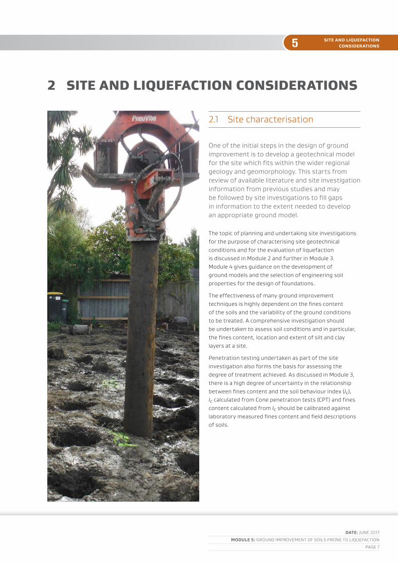
one of the initial steps in the design of ground improvement is to develop a geotechnical model for the site which fits within the wider regional geology and geomorphology. this starts from review of available literature and site investigation information from previous studies and may be followed by site investigations to fill gaps in information to the extent needed to develop an appropriate ground model.
the topic of planning and undertaking site investigations for the purpose of characterising site geotechnical conditions and for the evaluation of liquefaction is discussed in module 2 and further in module 3. module 4 gives guidance on the development of ground models and the selection of engineering soil properties for the design of foundations.
the effectiveness of many ground improvement techniques is highly dependent on the fines content of the soils and the variability of the ground conditions to be treated. a comprehensive investigation should be undertaken to assess soil conditions and in particular, the fines content, location and extent of silt and clay layers at a site.
penetration testing undertaken as part of the site investigation also forms the basis for assessing the degree of treatment achieved. as discussed in module 3, there is a high degree of uncertainty in the relationship between fines content and the soil behaviour index (Ic), Ic calculated from cone penetration tests (cpt) and fines content calculated from Ic should be calibrated against laboratory measured fines content and field descriptions of soils.
DATE: junE 2017
MoDulE 5: Ground ImprovEmEnt of SoIlS pronE to lIquEfactIon
paGE 8
5site and liquefaction considerations
2.2 liquefaction considerations
liquefaction evaluationliquefaction is associated with significant loss of soil stiffness and strength. the associated softening can result in large cyclic ground movements during shaking followed by subsidence and lateral spreads. these effects, either individually or as a combination, can be particularly damaging to the built environment.
Evaluation of the liquefaction hazard at a site involves three steps:
1 assessment of the susceptibility of the site soils to liquefaction
2 for soils that are susceptible to liquefaction, assessing the level of shaking that would trigger liquefaction or the development of significant excess pore water pressure
3 Evaluating the effects liquefaction will have on the building if liquefaction is triggered.
detailed recommendations on site investigations for assessment of liquefaction are given in module 2. Guidance on the identification and assessment of liquefaction, and liquefaction induced ground deformation is provided in module 3.
Effects of liquefaction on buildingsthe seismic behaviour of a building on liquefiable ground is affected by the depth and stiffness of the structural foundation, magnitude of contact pressure, seismic response of the structure and soil, the thickness and properties of liquefiable soil layers and the non-liquefiable crust, the intensity of ground motion and many other factors.
there are a number of ways liquefaction can affect a building and its connecting infrastructure, including:
• reduced bearing capacity due to the associated reduction in soil strength
• Subsidence associated with shear deformation, cyclic ratcheting, lateral spreading and ground re-levelling, and reconsolidation
• Surface ejection of soil and water (sand boils) from beneath or around foundations
• Heave of ground bearing floor slabs and buoyancy of buried pipes, tanks, chambers and basements
• Horizontal displacement and stretching of the footprint and foundation with lateral spreading.
• Kinematic bending of piles with horizontal ground displacements and
• pile down-drag (negative skin friction) caused by ground subsidence.
the degree to which these effects relate to a particular site and structure, depends on the site specific ground conditions and the details of the structural system. detailed discussion on the effects of liquefaction on buildings is given in module 4.

DATE: junE 2017
MoDulE 5: Ground ImprovEmEnt of SoIlS pronE to lIquEfactIon
paGE 9
5 ground improvement principles
3 Ground ImProvement PrInCIPLesthe objective of ground improvement, in this context, is to mitigate the effects of liquefaction and lateral spreading to the extent needed to meet the design performance criteria for the structure. performance requirements for ground improvement are discussed further in Section 7. Guidance on performance criteria for foundations is given in module 4.
3.1 methods of ground improvement
there are generally five principle methods employed to improve the ground and increase its resistance to liquefaction, these are:
• replacement
• densification
• Solidification
• reinforcement
• drainage.
Ground improvement methods utilise one or a combination of these mechanisms to improve the ground’s resistance to liquefaction and improve seismic performance. Ground improvement mechanisms are briefly described here and summarised in table 1. design issues pertaining to the most common techniques used in new Zealand are discussed further in Sections 6 to 10.

DATE: junE 2017
MoDulE 5: Ground ImprovEmEnt of SoIlS pronE to lIquEfactIon
paGE 10
5ground improvement principles
Note
a secondary mechanism of some techniques is the potential improvement of the soil’s resistance to liquefaction triggering by an increase in the lateral stress within the soil and thus changing its initial state. this mechanism cannot be easily verified in the field and may not greatly reduce the effects of liquefaction should it be triggered. until further research gives a better understanding of its effectiveness at mitigating liquefaction and ways to confidently verify that the increase in lateral stress is achieved in the field, this mechanism should not be depended on in design.
Replacementthe replacement method involves the removal of the insitu liquefiable soil, and replacement with a non-liquefiable material. It is useful for treatment of shallow liquefiable layers or creating a mat of dense uniform ground to support lightweight structures. the engineered replacement fill can be cement treated soil from the excavation or well graded dense gravel.
Densificationdensification is the most common mechanism of ground improvement and involves rearranging the soil particles into a tighter configuration, resulting in increased density. this increases the shear strength, stiffness and liquefaction resistance of the soil.
there are a variety of techniques available (refer to table 1). compaction techniques are most suited to sandy soils with low fines and can treat soils to depths of 4–12 m and deeper depending on the ground conditions, technique and plant. one of the major disadvantages is the noise and vibration produced during construction.
SolidificationSolidification involves either insitu mixing of cementitious or other additives into the soil or filling the voids with a reagent resulting in the soil particles being bound together. this will prevent the development of excess pore water pressure, preventing the occurrence of liquefaction.
Solidification techniques are typically expensive compared to other methods. Solidification techniques can be used to treat the full range of soils susceptible to liquefaction, including low plasticity silts to depths
of 30 m or more although there are some limitations with specific techniques. the advantages are: high confidence in the end product when the entire depth of liquefiable soil is treated, low vibration and noise during construction and the ability to treat beneath existing structures.
ReinforcementWhen saturated sand deposits are sheared during seismic loading, excess pore water pressure is generated reducing the stiffness and strength of the soil and increasing strains. the aim of reinforcement is to reduce shear deformation in the ground during an earthquake to mitigate the development of excess porewater pressures. the increased composite strength of the reinforced ground also mitigates ground deformation and subsidence of the structure if liquefaction were to occur.
reinforcement typically involves the construction of underground walls which usually intersect to form a lattice. the subterranean walls can be formed using ground solidification techniques or contiguous concrete piles. the advantages and disadvantages are similar to those for solidification except that it is less expensive and there is not the same level of confidence in prevention of development of excess porewater pressures in the soil contained within the lattice walls.
Grids of stiff isolated piles have been used to improve liquefiable soils by reinforcement. open grid systems are relatively flexible and do not offer the same degree of confinement as a lattice. they are less reliable than other methods of improvement and generally only applicable for lightweight structures and where the piles extend to a competent non-liquefiable stratum.
Drainagedrainage to mitigate liquefaction potential typically requires either:
• installation of vertical drains typically installed at 1–2 m intervals to allow the rapid dissipation of excess pore pressures generated during earthquakes to prevent liquefaction development, or
• desaturating potentially liquefiable soil, by permanently lowering groundwater or gas entrainment.
drainage methods are not widely used in new Zealand. vertical drains can be installed with relatively low vibration and noise compared to compaction methods and are typically cheaper than solidification.

geotechnical investigations for earthquake engineering
DATE: junE 2017
MoDulE 5: Ground ImprovEmEnt of SoIlS pronE to lIquEfactIon
paGE 11
5
However, the required drain spacing is sensitive to the soil permeability which is difficult to measure, their effectiveness cannot be verified and if liquefaction is triggered, they do not constrain ground movement.
permanent dewatering can be a useful means of treatment when pumping is not involved and the water can easily be disposed of. If continuous pumping is necessary, there can be substantial ongoing running and maintenance costs and there is a risk of failure in aftershocks if the dewatering system is damaged in the initial earthquake.
3.2 Seismic response of buildings supported on improved ground
Effects on structural responseGround improvement can greatly increase the stiffness of the soil profile. It is well understood that the stiffness of the soil has a marked effect on seismic ground motions at the surface. Stiffening the soil can amplify accelerations at the surface but decrease displacements.
Deformation modesWell engineered improved ground has proven to perform well in previous earthquakes (mitchell & Wentz, 1991). the following paragraphs discuss deformation mechanisms and behavioural characteristics that need to be considered in the well engineered design of ground improvement to mitigate liquefaction.
In many cases, ground improvement will not eliminate the effects of liquefaction. Settlement of buildings with shallow foundations supported on improved ground will result from shear and volumetric changes within the improved zone and in the soils surrounding or underlying the improved zone. module 4 discusses foundation performance in detail.
the prevalent mode of deformation depends on the ground improvement method adopted, its size and stiffness; the size, weight and stiffness of the structure (and the distribution of weight and stiffness) and the extent of the liquefiable soil beneath the improved zone.
Except for methods that completely solidify or replace the liquefiable soils with stiff (cemented) low permeability materials, subsidence, can develop from shear deformation in the improved ground under loading from the building. this is often more pronounced at the perimeter of structures, particularly for tall and heavy structures that can exert large loads on perimeter foundations. the magnitude of subsidence can be exacerbated by softening of the improved soils with cyclic shearing, the associated development of excess porewater pressure and the migration of excess porewater pressures from the surrounding liquefied soil into the improved zone. reconsolidation of soils in the improved zone as excess pore-pressures dissipate will cause additional subsidence.
lattice and columnar reinforcement elements can be subjected to considerable bending, shear and axial stress.
With partial depth of improvement, settlement and tilting of the improved ground overall can develop from shear induced deformation in the liquefied soil beneath the improved zone, reconsolidation of the liquefied soils as porewater pressures dissipate and ratcheting effects during earthquakes, similar to the mechanisms of settlement for shallow foundations on liquefaction prone sites as described in module 4.
Ground improvement in areas of lateral spreading can experience large compression and tension stresses from dynamic and kinematic forces imposed on it by the surrounding spreading ground. this can cause horizontal displacement, stretching and shear deformation of the zone of ground improvement.

DATE: JUNE 2017
MODULE 5: GROUND IMPROVEMENT OF SOILS PRONE TO LIQUEFACTION
PAGE 13
DATE: JUNE 2017
MODULE 5: GROUND IMPROVEMENT OF SOILS PRONE TO LIQUEFACTION
PAGE 12
55 ground improvement principles
ground improvement principles
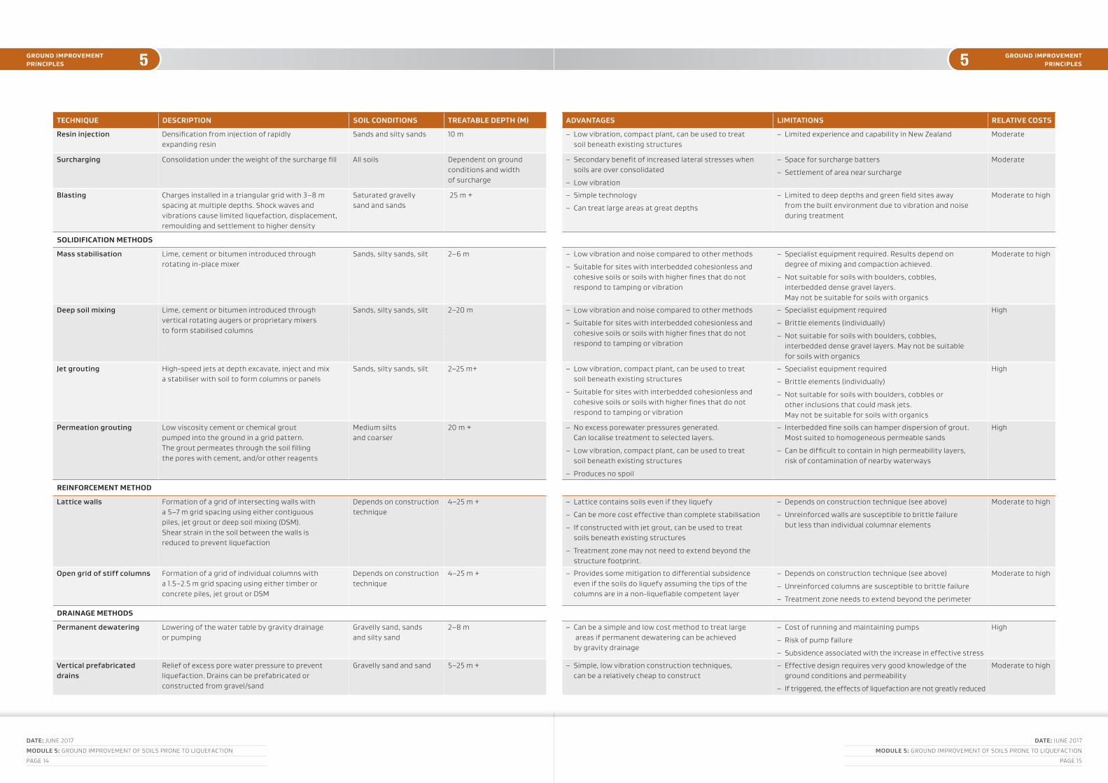
Table 1: Ground improvement techniques
TECHNIQUE DESCRIPTION SOIL CONDITIONS TREATABLE DEPTH (M) ADVANTAGES LIMITATIONS RELATIVE COSTS
REPLACEMENT
Dense gravel replacement Excavation of liquefiable soils and replacement with dense gravel
All soils 2–6 m – Uses conventional construction equipment and methods
– High confidence in level of treatment
– Dewatering and temporary shoring may be necessary
– Subsidence of neighbouring properties associated with dewatering
– Moderate vibration and noise with compaction of replacement materials
Low
Stabilised soil replacement Excavation of liquefiable soils and replacement with stabilised soil
All soils 2–6 m – Can treat the excavated soil and return to excavation (no cut to waste or fill import)
– High confidence in level of treatment
Low to moderate
DENSIFICATION METHODS
Dynamic compaction Compaction of soils by repeated dropping of a 5–20 T tamper from a crane in a 2–6 m grid
Gravels, sand and silty sand
4–7 m – Fast and economic
– Moderate experience in NZ, extensive experience overseas. Proven effectiveness in earthquakes
– Easily verifiable
– High vibration and noise, not suitable in built up areas
– Clearance for crane
– Full scale trial typically required to confirm effectiveness and refine the design
Low
Dynamic replacement Construction of 2–3 m diameter gravel piers in a 6–12 m grid with dynamic compaction equipment
Sands, silty sands and silt
4–7 m
Impact roller compaction Compaction of near surface soils with a square sided high energy roller pulled behind a tractor
Gravels sands and silty sand
2–4 m – Fast and economic
– Easily verifiable
– Specialist equipment required
– Limited depth of improvement, especially for sites with interbedded layers of silt
– High vibration, not suitable in built up areas
Low
Vibro-compaction Densification by vibration with a vibroflot hung from a crane in a 1.8–3.0 m square or triangular grid
Gravelly sand, sand and sand with minor silt
6–25 m + – Secondary benefits of increased lateral stress
– High level of construction quality control available
– Can treat to large depths
– Easily verifiable, proven effectiveness in earthquakes
– Requires specialist equipment
– Moderate vibration, not suitable near existing structures
– Containment and treatment of sediment produced during construction
– Clearance for crane
Moderate
Vibro-replacement Construction of dense granular columns using a vibroflot in a 1.8–3.0 m square or triangular grid
Gravelly sand, sands, silty sand, silt
6–25 m + – Secondary benefits of reinforcement, drainage and increased lateral stress
– High level of construction quality control available
– Extensive experience in NZ and overseas
– Proven effectiveness in earthquakes
– Can treat to large depths
– Easily verifiable
– Requires specialist equipment
– Moderate vibration, not suitable near existing structures
– Containment and treatment of sediment produced during construction
– Clearance for crane
– Not suitable for soils containing cobbles, boulders or other large inclusions
Moderate
Granular compaction piles Densification by vibration and displacement with gravel to form columns in a 1.5–2.5 m grid
Sands, silty sand, silt Up to 16 m – Secondary benefits of reinforcement, drainage and increased lateral stress
– Extensive experience in NZ and overseas. Proven effectiveness in earthquakes
– Can be constructed using conventional equipment
– Dry method, less sediment to manage compared to wet vibro-replacement
– Moderate vibration, not suitable near existing structures
– Clearance for equipment
Moderate
Displacement auger piles Construction of granular or concrete columns in a 1.5–2.5 m grid with a displacement auger
Sands, silty sand, silt Up to 16 m – Secondary benefits of reinforcement, drainage (for granular columns) and increased lateral stress
– Low vibration construction
– Can be used near existing structures when allowance is made for heave around columns
– Requires specialist equipment
– Not as effective at compacting sands as compaction piles
– Clearance for equipment
Moderate
Driven compaction piles Densification by displacement and vibration with driven (timber or precast concrete) piles in a 1.2–1.6 m grid
Sands, sand with some silt
Up to 16 m – Secondary benefits of increased lateral stress. Some reinforcement possible but typically low friction between piles and soil limits reinforcement effects
– Heave of ground near improvement piles
– Moderate vibration and noise, not suitable immediately adjacent existing structures
Moderate
Compaction grouting Highly viscous grout acts as radial hydraulic jack when pumped in under high pressure
Sands and silty sand 25 m – Low vibration, compact plant, can be used to treat soil beneath existing structures
– Not suitable for treatment at shallow depths where there are low confining pressures.
Moderate
DATE: JUNE 2017
MODULE 5: GROUND IMPROVEMENT OF SOILS PRONE TO LIQUEFACTION
PAGE 15
DATE: JUNE 2017
MODULE 5: GROUND IMPROVEMENT OF SOILS PRONE TO LIQUEFACTION
PAGE 14
55ground improvement principles
ground improvement principles
TECHNIQUE DESCRIPTION SOIL CONDITIONS TREATABLE DEPTH (M) ADVANTAGES LIMITATIONS RELATIVE COSTS
Resin injection Densification from injection of rapidly expanding resin
Sands and silty sands 10 m – Low vibration, compact plant, can be used to treat soil beneath existing structures
– Limited experience and capability in New Zealand Moderate
Surcharging Consolidation under the weight of the surcharge fill All soils Dependent on ground conditions and width of surcharge
– Secondary benefit of increased lateral stresses when soils are over consolidated
– Low vibration
– Space for surcharge batters
– Settlement of area near surcharge
Moderate
Blasting Charges installed in a triangular grid with 3–8 m spacing at multiple depths. Shock waves and vibrations cause limited liquefaction, displacement, remoulding and settlement to higher density
Saturated gravelly sand and sands
25 m + – Simple technology
– Can treat large areas at great depths
– Limited to deep depths and green field sites away from the built environment due to vibration and noise during treatment
Moderate to high
SOLIDIFICATION METHODS
Mass stabilisation Lime, cement or bitumen introduced through rotating in-place mixer
Sands, silty sands, silt 2–6 m – Low vibration and noise compared to other methods
– Suitable for sites with interbedded cohesionless and cohesive soils or soils with higher fines that do not respond to tamping or vibration
– Specialist equipment required. Results depend on degree of mixing and compaction achieved.
– Not suitable for soils with boulders, cobbles, interbedded dense gravel layers. May not be suitable for soils with organics
Moderate to high
Deep soil mixing Lime, cement or bitumen introduced through vertical rotating augers or proprietary mixers to form stabilised columns
Sands, silty sands, silt 2–20 m – Low vibration and noise compared to other methods
– Suitable for sites with interbedded cohesionless and cohesive soils or soils with higher fines that do not respond to tamping or vibration
– Specialist equipment required
– Brittle elements (individually)
– Not suitable for soils with boulders, cobbles, interbedded dense gravel layers. May not be suitable for soils with organics
High
Jet grouting High-speed jets at depth excavate, inject and mix a stabiliser with soil to form columns or panels
Sands, silty sands, silt 2–25 m+ – Low vibration, compact plant, can be used to treat soil beneath existing structures
– Suitable for sites with interbedded cohesionless and cohesive soils or soils with higher fines that do not respond to tamping or vibration
– Specialist equipment required
– Brittle elements (individually)
– Not suitable for soils with boulders, cobbles or other inclusions that could mask jets. May not be suitable for soils with organics
High
Permeation grouting Low viscosity cement or chemical grout pumped into the ground in a grid pattern. The grout permeates through the soil filling the pores with cement, and/or other reagents
Medium silts and coarser
20 m + – No excess porewater pressures generated. Can localise treatment to selected layers.
– Low vibration, compact plant, can be used to treat soil beneath existing structures
– Produces no spoil
– Interbedded fine soils can hamper dispersion of grout. Most suited to homogeneous permeable sands
– Can be difficult to contain in high permeability layers, risk of contamination of nearby waterways
High
REINFORCEMENT METHOD
Lattice walls Formation of a grid of intersecting walls with a 5–7 m grid spacing using either contiguous piles, jet grout or deep soil mixing (DSM). Shear strain in the soil between the walls is reduced to prevent liquefaction
Depends on construction technique
4–25 m + – Lattice contains soils even if they liquefy
– Can be more cost effective than complete stabilisation
– If constructed with jet grout, can be used to treat soils beneath existing structures
– Treatment zone may not need to extend beyond the structure footprint.
– Depends on construction technique (see above)
– Unreinforced walls are susceptible to brittle failure but less than individual columnar elements
Moderate to high
Open grid of stiff columns Formation of a grid of individual columns with a 1.5–2.5 m grid spacing using either timber or concrete piles, jet grout or DSM
Depends on construction technique
4–25 m + – Provides some mitigation to differential subsidence even if the soils do liquefy assuming the tips of the columns are in a non-liquefiable competent layer
– Depends on construction technique (see above)
– Unreinforced columns are susceptible to brittle failure
– Treatment zone needs to extend beyond the perimeter
Moderate to high
DRAINAGE METHODS
Permanent dewatering Lowering of the water table by gravity drainage or pumping
Gravelly sand, sands and silty sand
2–8 m – Can be a simple and low cost method to treat large areas if permanent dewatering can be achieved by gravity drainage
– Cost of running and maintaining pumps
– Risk of pump failure
– Subsidence associated with the increase in effective stress
High
Vertical prefabricated drains
Relief of excess pore water pressure to prevent liquefaction. Drains can be prefabricated or constructed from gravel/sand
Gravelly sand and sand 5–25 m + – Simple, low vibration construction techniques, can be a relatively cheap to construct
– Effective design requires very good knowledge of the ground conditions and permeability
– If triggered, the effects of liquefaction are not greatly reduced
Moderate to high

DATE: junE 2017
MoDulE 5: Ground ImprovEmEnt of SoIlS pronE to lIquEfactIon
paGE 16
5performance requirements
4 PerformanCe requIrements
before selecting and designing a ground improvement system to mitigate liquefaction effects at a site, it is necessary to understand the performance requirements of the improved ground and the structural system.
this section briefly discusses the minimum regulatory performance requirements for building work in new Zealand, the elements and interactions between elements that affect the performance of structures on sites with ground improvement to mitigate liquefaction and the performance criteria for ground improvement.
4.1 regulatory requirements
the new Zealand building code specifies the minimum requirements for performance of new buildings in new Zealand. new buildings are typically designed for two limit (or damage) states, the serviceability limit state (SlS) and the ultimate limit state (ulS). more important buildings are also designed for a third limit state, SlS 2.
the ulS is concerned with avoiding instability and collapse in rare events throughout the life of the building. the SlSs are concerned with maintaining amenity and restricting damage in relatively more frequent and smaller events in the life of a structure. module 4 gives more detailed discussion of the legislative requirements.
currently in new Zealand differences arise in the performance requirements between new and existing structures. for existing structures, the minimum legal requirement, specified in the redbook, (assessment and Improvement of the Structural performance of buildings in Earthquakes, 2006) is less than the new building standard.

DATE: junE 2017
MoDulE 5: Ground ImprovEmEnt of SoIlS pronE to lIquEfactIon
paGE 17
5 performance requirements
4.2 Ground improvement performance objectives
the general philosophy for the design of ground improvement is to eliminate liquefaction and lateral spreading or mitigate their effects to the extent needed to meet the design performance criteria for the structure. In this context, the effectiveness of ground improvement should be assessed within the performance-based design framework by estimating the reduction of effects of liquefaction in relation to a no-improvement case, and by assessing the seismic response in relation to specific performance objectives for earthquake loads associated with different return periods. qualitative effects of ground improvement on the dynamic response of foundation soils, structure and soil-structure system should be also considered in this evaluation. Such relatively rigorous performance requirements imply the need for adequate standards for design, construction control and verification of the effectiveness of ground improvement.
performance criteria for the acceptable damage, settlement and differential settlement for each damage state should be developed collaboratively between the owner/developer, structural engineer and geotechnical specialist to get an overall system that meets regulatory (minimum) requirements and the expectations of the owner/developer.
It is often not economic, nor required in a regulatory sense, to completely eliminate liquefaction beneath buildings with ground improvement. apart from methods that completely solidify or replace all liquefiable soils with non-liquefiable material, excess pore water pressures can develop within the zone of improvement. the frequency of earthquake at which these aspects start to have a significant effect on the amenity of the structure should be discussed and agreed with the owner/developer.
consideration should be given to the resilience of the ground treatment and the overall response should be ductile. the weight and stiffness of the structure and its foundations; the type, extent, and stiffness of the ground improvement; the ground conditions, characteristics of earthquake shaking and the extent of liquefaction triggered in an earthquake, all affect seismic performance. In assessing seismic performance and resilience, the uncertainties in these parameters and the interaction between the superstructure, connecting infrastructure, foundation, improved ground and native soil need to be considered holistically. the high degree of uncertainty in many of the parameters affecting seismic response implies the need to assess the sensitivity of the system response to each parameter
and apply an appropriate level of redundancy in the design. Sensitivity assessment should be undertaken as part of any ground improvement design and discussed within the foundation options and design reports.
Improved structural measures that can be incorporated to reduce damage susceptibility due to liquefaction, improve resilience and reduce or eliminate the need for ground improvement. these can comprise:
• use of robust matts or a stiff grid of intersecting ground beams instead of standalone footings.
• making above ground structural elements or connections between structures flexible and ductile to cope with total and differential settlements or lateral spread.
• constructing foundation systems that seismically isolate the building from the ground and allow it to be relevelled.
• pile foundations to competent ground that is not underlain by liquefiable soils to prevent bearing failure and mitigate settlement and uplift (buoyancy).
• control of ground deformation and structural performance by structural measures (rigidity of the structure, rigid rafts, sheet piles to confine liquefiable material, geogrids, base isolation of structures).
consideration also needs to be given to the performance requirements for auxiliary facilities, emergency egress facilities and connecting utilities. utilities are susceptible to damage at the margins of ground improved zones due to the discontinuity in soil properties and stiffness.

DATE: junE 2017
MoDulE 5: Ground ImprovEmEnt of SoIlS pronE to lIquEfactIon
paGE 18
5ground improvement design
5 Ground ImProvement desIGn
5.1 design process
Engineering assessment, consideration and design process for ground improvement can be summarised as follows:
• determine performance requirements for the building and its foundation system (refer to the nZ building code, nZS1170, module 1 and module 4 and nZSEE assessment and Improvement of the Structural performance of buildings in Earthquakes).
• assess site conditions, ground conditions and geohazards (geologic hazards) including seismicity and susceptibility to liquefaction and lateral spreading (refer to modules 1, 2 and 3). Where existing geotechnical information is insufficient, a geotechnical investigation should be carried out (refer to module 2).
• assess if liquefaction will be triggered, severity of liquefaction and the free field effects of liquefaction at the site (refer to module 3).
• assess the lateral spreading hazard at the site and the potential for differential lateral displacement across the building footprint.
• assess the effects of liquefaction on the structure (with shallow or pile foundations and no ground improvement) and compare with the performance criteria. consider whether there are readily available structural options to reduce susceptibility to damage from liquefaction. Where reasonable structural options alone are not sufficient to satisfy the performance requirements, consider ground improvement options.
• Select suitable methods for ground improvement (refer to Section 5.2).
• design the extent (depth and size in plan) of improvement needed to meet design objectives. consider soil-ground improvement-structure interaction. Early engagement between the structural and geotechnical engineers, and where practicable contractors, will enable a more efficient and holistic assessment of ground improvement and foundation options (also refer to module 4).

DATE: junE 2017
MoDulE 5: Ground ImprovEmEnt of SoIlS pronE to lIquEfactIon
paGE 19
5 ground improvement design
• design the size and arrangement of the ground improvement; determine material requirements, eg unconfined compressive strength of soil-cement mixture.
the usual goal of ground improvement is to eliminate liquefaction. However ground improvement does not necessarily need to eliminate liquefaction within the improved zone but should control and mitigate the effects of liquefaction, and meet the performance criteria.
• determine quality control (qc) and quality assurance (qa) requirements.
In many cases a ground improvement trial will be required to confirm design assumptions and qa methods and optimise the design.
5.2 Selection of ground improvement method
the following factors should be considered when selecting an appropriate remediation technique:
• the required performance of the ground improvement system, its durability, reliability and resilience within the context of the overall structure-foundation-ground improvement-ground system.
• the effectiveness of each method to treat the site soil conditions and meet the performance requirements. further guidance on the suitability of techniques to treat different soil types is presented in table 1 and discussed in Sections 6–10.
• Site constraints (space to boundary, etc).
• construction constraints (noise, vibration, contamination, resources and specialist plant and labour availability).
• field verifiability.
• Environmental impact eg settlement from permanent drainage and effects on neighbouring infrastructure.
• cost.
• Safety in design.
5.3 Extent of ground improvement below buildings with shallow footings
Generally, even when the soil undergoes liquefaction over a wide area and considerable depth, the region requiring improvement is limited to the zone which controls the stability and structural performance of the structure.
In principle, the minimum depth and lateral extent of improvement required is dependent on many factors, such as ground conditions, type of ground improvement, purpose of ground improvement (ie to mitigate lateral spreading or settlement, or both), performance requirements, foundation type, depth of liquefaction, and interaction between structure, improved ground and natural ground at the perimeter of the improved section. moreover, the extent of improvement is dependent on the stiffness of the improved ground, generally set to meet performance requirements.
this section presents simple approaches for determining the extents of ground improvement for normal importance, small to medium buildings and as a first stage of design for higher importance, heavy or complex structures.
Effective stress dynamic numerical analysis of the structure, its foundations, the improved ground and the surrounding natural soils is a useful and sometimes necessary tool for design from the perspective of understanding the complex system interactions and its capacity to predict strains and displacements. However, dynamic effective stress numerical analyses techniques are not appropriate for all situations and are typically only viable for large complex projects. modules 3 and 4 discuss numerical analysis in more detail.
Depth of treatmentIdeally, the full depth of liquefiable soils should be treated beneath a structure. this eliminates subsidence from cyclic ratcheting, shear deformation and reconsolidation of liquefied soils that otherwise underlie the improved zone. It also eliminates softening of the improved zone with the upward dissipation of excess porewater pressures from the liquefied soils beneath and the potential for seepage erosion of soil under the improvement zone.

DATE: junE 2017
MoDulE 5: Ground ImprovEmEnt of SoIlS pronE to lIquEfactIon
paGE 20
5ground improvement design
full depth improvement is unlikely to be economic for sites underlain by deep liquefiable deposits and partial depth improvement can often give acceptable performance by reducing the magnitude of settlement. assessment of nearly 60,000 lightweight single family dwellings in christchurch following the canterbury Earthquake Sequence clearly showed that less structural damage occurred in liquefaction prone areas containing an intact relatively stiff non-liquefying crust that was at least 3 m thick (Wansbone and van ballegooy, 2015)
from case history studies, Hausler and Sitar (2001) noted that one of the reasons why unacceptable performance was noted in the majority of ground improvement cases they investigated was due to inadequate remediation zone depth. centrifuge studies on this topic (liu and dorby, 1997; Hausler 2002) came to a similar conclusion.
figure 1 summarises measured settlement (normalised against the thickness of the liquefiable layer) vs portion of depth of liquefiable soils treated from case studies and centrifuge tests. the case studies and centrifuge tests indicate a marked increase in settlement for treatment depths that are less than 50% of the thickness of the liquefiable layer.
note that for the two outlier cases, the magnitude of settlement at these sites were compounded by lateral spreading.
the case histories and centrifuge testing highlights the importance of taking a cautious approach and due account of the increased performance uncertainty when designing solutions with partial depth of treatment.
In a simplified approach, the bearing capacity of the improved ground (considering it to be a rigid body) should be assessed using conventional bearing capacity theory (see module 4) with reduced strengths and stiffness for liquefiable soils to establish a minimum depth of improvement.
the improved zone needs to be stiff enough to bridge liquefiable soils. the overall stiffness of the improved zone is a function of both the modulus of the improved zone and its depth. psuedo-static numerical analysis can be used to give some insight into the deformation characteristics and adequacy of the depth of improvement to mitigate differential settlement of the structure. In this analysis, the stiffness of the improved zone may need to be reduced for the effects of excess porewater pressure developed from cyclic loading during earthquake shaking and migration from adjacent and underlying liquefied soils.
Figure 1: Normalised improvement depth vs normalised building settlement (Liu and Dorby 1997, Hausler 2001, 2002)
foun
dati
on s
ettl
emen
t/to
tal t
hick
ness
(%) 5
Key
EaH small port island
pWrI small port island
liu and dobry 0.2 Sine
pGa greater than 0.3 g
pGa less than 0.3 g
4
3
2
1
00 0.2 0.4 0.6 0.8 1.0
Improved thickness/total liquefiable thickness
DATE: junE 2017
MoDulE 5: Ground ImprovEmEnt of SoIlS pronE to lIquEfactIon
paGE 21
5
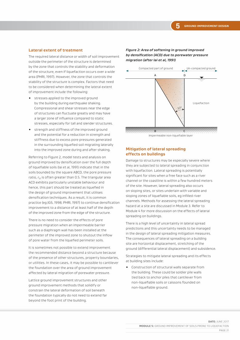
lateral extent of treatmentthe required lateral distance or width of soil improvement outside the perimeter of the structure is determined by the zone that controls the stability and deformation of the structure, even if liquefaction occurs over a wide area (pHrI, 1997). However, the zone that controls the stability of the structure is complex. factors that need to be considered when determining the lateral extent of improvement include the following:
• stresses applied to the improved ground by the building during earthquake shaking. compressional and shear stresses near the edge of structures can fluctuate greatly and may have a larger zone of influence compared to static stresses, especially for tall and slender structures.
• strength and stiffness of the improved ground and the potential for a reduction in strength and stiffness due to excess pore pressures generated in the surrounding liquefied soil migrating laterally into the improved zone during and after shaking.
referring to figure 2, model tests and analysis on ground improved by densification over the full depth of liquefiable soils (Iai et al, 1991) indicate that in the soils bounded by the square abcd, the pore pressure ratio, ru is often greater than 0.5. the triangular area acd exhibits particularly unstable behaviour and hence, this part should be treated as liquefied in the design of ground improvement that utilises densification techniques. as a result, it is common practice (eg jGS, 1998; pHrI, 1997) to continue densification improvement to a distance of at least half of the depth of the improved zone from the edge of the structure.
there is no need to consider the effects of pore pressure migration when an impermeable barrier such as a diaphragm wall has been installed at the perimeter of the improved zone to shutout the inflow of pore water from the liquefied perimeter soils.
It is sometimes not possible to extend improvement the recommended distance beyond a structure because of the presence of other structures, property boundaries, or utilities. In these cases, it may be possible to cantilever the foundation over the area of ground improvement affected by lateral migration of porewater pressure.
lattice ground improvement structures and other ground improvement methods that solidify or constrain the lateral deformation of soil beneath the foundation typically do not need to extend far beyond the foot print of the building.
Figure 2: Area of softening in ground improved by densification (ACD) due to porewater pressure migration (after Iai et al, 1991)
Mitigation of lateral spreading effects on buildingsdamage to structures may be especially severe where they are subjected to lateral spreading in conjunction with liquefaction. lateral spreading is potentially significant for sites when a free face such as a river channel or the coastline is within a few hundred meters of the site. However, lateral spreading also occurs on sloping sites, or sites underlain with variable and sloping zones of liquefiable soils, eg infilled river channels. methods for assessing the lateral spreading hazard at a site are discussed in module 3. refer to module 4 for more discussion on the effects of lateral spreading on buildings.
there is a high level of uncertainty in lateral spread predictions and this uncertainty needs to be managed in the design of lateral spreading mitigation measures. the consequences of lateral spreading on a building site are horizontal displacement, stretching of the ground (differential lateral displacement) and subsidence.
Strategies to mitigate lateral spreading and its effects at building sites include:
• construction of structural walls separate from the building. these could be soldier pile walls tied back to anchor piles that cantilever from non-liquefiable soils or caissons founded on non-liquefiable ground.
ground improvement design
compacted part of ground un-compacted ground
liquefaction
Impermeable non-liquefiable layer
30°
A D
B C

DATE: junE 2017
MoDulE 5: Ground ImprovEmEnt of SoIlS pronE to lIquEfactIon
paGE 22
5ground improvement design
• using a buttress of ground improvement on the down slope side of the building but separate from the building foundations. this may be desirable for piled structures in laterally spreading zones as the greater stiffness and strength of the improved soils could place larger kinematic loads on the piles and increase structural inertia.
• Improving the ground under the structure to mitigate lateral spreading as well as provide a suitable platform for the building.
• a combination of these treatments except that ground improvement should extend under the entire footprint of the building or not at all to avoid high contrasts in stiffness beneath the building that could cause differential subsidence and increase torsional response.
currently, field case histories and research to support guidelines on the extent of the treatment zone to guard against lateral spreading are scarce, and if available, they are not comprehensive. It is known that the area that controls the stability and deformation of the structure when subjected to lateral spreading is complex and the size of zone that is necessary to protect the structure from significant lateral deformation and subsidence associated with lateral spreading requires careful consideration.
a simplified approach to determine the extent of the treatment zone is by calculating the extent of improvement needed to get a factor of safety of 1.1 with post-earthquake strengths for the native and improved ground. Satisfaction of this criteria should mean that the ground does not spread substantially after the earthquake has passed but will not entirely prevent horizontal displacement and deformation beneath the structure.
lateral deformation of the improved zone can be estimated by applying horizontal pressure to the upslope side of the improved zone and frictional loads along the sides of the improved zone parallel to the direction of spreading, using an average shear modulus for the improved ground, reduced for stress strain non-linearity and any anticipated excess pore pressure. Some recommendations for calculation of the applied horizontal loads is given in pHrI (1997) and jGS (1998).
the front of the improved zone will practically be unsupported by the spreading ground and the associated drag friction on the sides of the zone will vary spatially, reducing with depth and increasing distance from the front of the improved block inducing tension in the front of the improved zone.
at sites where there is potential for lateral spreading, foundation elements should be well tied together to reduce the risk of elongation between supports. a slip layer beneath shallow foundations, constructed from two layers of HdpE sheet for example, can also be used to isolate the structure from stretching. When selecting the method of improvement to mitigate lateral spreading, consideration needs to be given to differential lateral displacement and stretching within the improved zone.
5.4 drainage blankets
apart from methods that solidify the ground or replace it with cemented non-liquefiable materials, some development of excess porewater pressure is almost inevitable within the improved zone in strong earthquake shaking. potential migration of excess porewater pressures from liquefiable soil below or around the improved zone may further exacerbate porewater pressures in the improved ground beneath structures.
Except for ground treatment involving replacement with clean granular fill or full depth solidification, a filtered drainage blanket should be installed over the improved zone for all new builds and where there is suitable access. the drainage blanket should be designed to allow relief of excess pore pressures without ejecting soil on the surface or causing uplift on the base of ground bearing floors or shallow foundations. Gravel drainage blankets also improve the distribution of loads from shallow foundations across the stiff inclusions (piles for example) within the improved zone. bS8006 describes load transfer mechanisms and gives design recommendations.

DATE: junE 2017
MoDulE 5: Ground ImprovEmEnt of SoIlS pronE to lIquEfactIon
paGE 23
5 ground improvement design
Where only partial depth of liquefied soils are solidified or replaced with stabilised soil, the drainage blanket protects against ejecta penetrating through cracks and alleviates the effects abrupt differential movement at cracks. a perimeter subsoil drain installed around the outside of the improved area to relieve water pressure and prevent soil seepage erosion at the edges of solidified zones or lattice structures is prudent where the improved zone does not extend beyond the perimeter of the structure.
drainage blankets should be a minimum of 300 mm thick and consist of clean aggregate either placed on a filter fabric or with a grading designed to filter the subgrade.
5.5 other considerations
quality control and quality assurance
the effectiveness of ground improvement is highly dependent on the skill of the constructors and the construction equipment used. the importance of post improvement testing to verify the required level of treatment has been achieved, where possible cannot be over emphasised.
a range of construction quality control methods have been developed and continue to be developed. these include, for example, automatic measurement of probe depth and compaction time between lifts for vibro-compaction or the quantity of stone placed per metre depth of stone column. construction quality control is essential for the production of a consistent product and understanding issues that may arise from quality assurance testing to verify the treatment effectiveness. construction quality control should not be seen as a substitute for quality assurance with post treatment verification of improvement.
all construction quality control and quality assurance records should be supplied to the consenting authority together with the relevant producer statements on completion of the ground treatment.
Environmental constraints
the following environmental constraints need to be considered in the design of ground improvement:
• the space available for construction
• noise and vibration effects on adjacent properties during construction
• the potential for temporary and permanent changes to the groundwater regime
• whether there is a ground or groundwater contamination hazard at the site
• the archaeological significance of the site.
most ground improvement techniques use relatively inert materials and in themselves do not contaminate the ground. the exceptions are some non-cementitious grouts and, to a lesser extent, some treated timber piles.
on the other hand, ground improvement can increase the dispersion of pre-existing ground contaminants either through the construction process (eg with the excavation of contaminated soil) or while in service (eg cross contamination of aquifers) and can be a health and safety hazard. a ground contamination hazard assessment may be carried out during the design phase. Even if site investigations and assessment indicate a low contamination hazard, protocols should be put in place for the management of contaminated soils if they are encountered during construction.
It is important to note that it will be necessary to comply with various requirements relating to hours of work, erosion and sediment control, contamination of groundwater, rivers, lakes and the sea, construction noise and vibration.
Ground improvement can damage tree roots and underground services. this should also be taken into account while considering the ground improvement options and footprint.
for geothermal sites, the effect of ground improvement on the geothermal regime of the site and potential hazards (geothermal chemicals in groundwater, stream and other gases under pressure, potential for hydrothermal eruption, geothermally altered ground etc.) should be considered in the design process.

DATE: junE 2017
MoDulE 5: Ground ImprovEmEnt of SoIlS pronE to lIquEfactIon
paGE 24
5replacement method
6 rePLaCement methods
6.1 outline
the replacement method involves the removal of the insitu liquefiable material, and replacement with a non-liquefiable material. the replacement material may be non-liquefiable by composition or by density/stress state. Well compacted, well graded gravel or soil mixed with cement or other additives are commonly used for replacement in liquefaction remediation.
Where ground conditions are suitable it may be possible to remove and recompact the same material to a higher density.
replacement with dense granular fill has been a common method of ground improvement in the rebuild of christchurch following the 2011 christchurch earthquake. the method was proven effective at mitigating differential subsidence for lightweight structures in the ground improvement trials undertaken by Eqc in 2013.
there is a high degree of confidence in the ability of the replacement soil to resist liquefaction and it uses construction equipment and practices that are widely available and easily tested.
6.2 Site conditions suitable for replacement
the replacement method is most suited for areas with a shallow liquefiable layer but replacement can also be used to form a uniform stiff platform for new structures where acceptable structural performance can be achieved by only partial replacement of the depth of liquefiable soils. the replacement method can be used to treat both sands and silts.
the depth of treatment is typically limited by the feasibility of excavating and dewatering for placement and compaction of materials below the water table and, where the site is near existing structures, the cost of temporary excavation support to protect neighbouring structures from damage.
6.3 design considerations
module 5a includes specifications for the construction of dense gravel mats for lightweight residential structures. these can be adapted for use with larger structures.
placement of a limited depth of clean, open graded granular fill or tremied stabilised flowable fill could be used for construction of replacement fill below water level. Where compaction of backfill below water level is required design should consider the risk and potential consequences of the required density not being achieved.
dewatering can affect a wide area beyond the site and the associated increase in effective stress can cause subsidence at the site and in neighbouring buildings. the risk of subsidence is greatest when there are organics and soft soils. powers et al (2007) gives guidance on practical solutions and design methods for dewatering.
It is good practice to place a layer of filter fabric and geogrid below granular replacement fill. these facilitate compaction of the initial fill layers, mitigate migration of fines from underlying layers with dissipation of excess porewater pressures and provide some protection against lateral stretch. because of their low axial stiffness, a single layer of geogrid typically does little to increase the overall flexural stiffness of a granular raft.
cement stabilised soils are brittle and have low strength in tension. the replacement dimensions and modulus should be designed to avoid concentration of strains at large widely spaced cracks that could cause abrupt differential settlement of the structure. this is especially important where only partial depth of soils prone to liquefaction are treated. a granular layer placed over the cemented fill can smooth out abrupt changes in level or grade beneath shallow foundations.
the compaction of replacement materials can involve moderate levels of noise and vibration that could be a nuisance or damaging to neighbouring properties. nZS 6803 provides guideline noise limits and management practices for construction works. the State Highway construction and maintenance noise and vibration guide provides practical information and advice on prediction, management and mitigation measures.
DATE: junE 2017
MoDulE 5: Ground ImprovEmEnt of SoIlS pronE to lIquEfactIon
paGE 25
5 densification methods
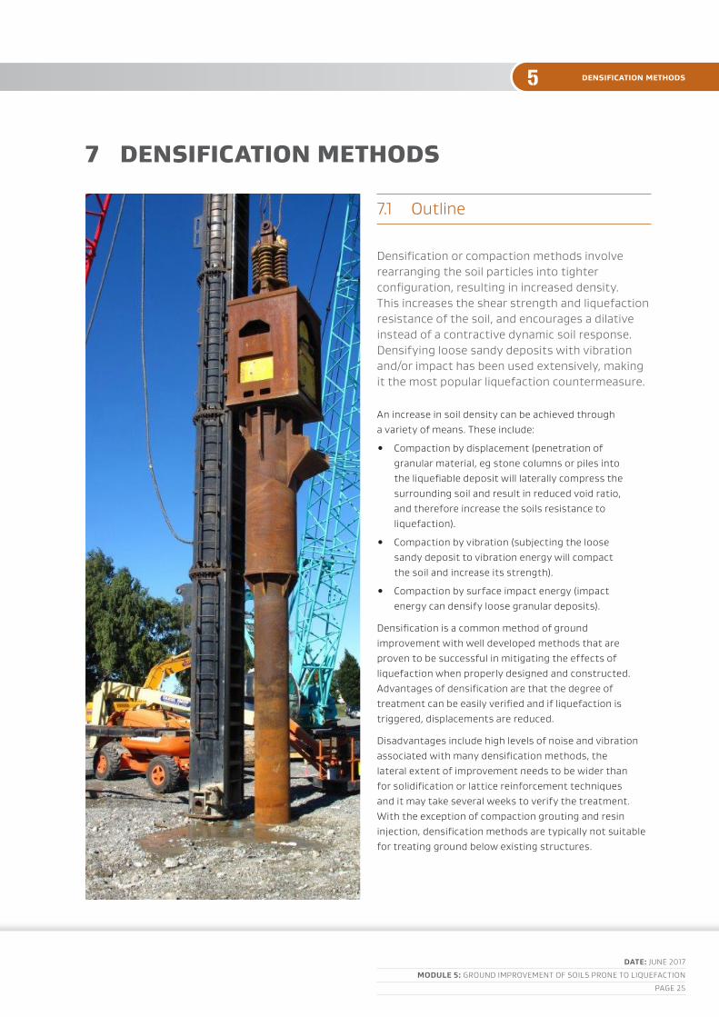
7 densIfICatIon methods
7.1 outline
densification or compaction methods involve rearranging the soil particles into tighter configuration, resulting in increased density. this increases the shear strength and liquefaction resistance of the soil, and encourages a dilative instead of a contractive dynamic soil response. densifying loose sandy deposits with vibration and/or impact has been used extensively, making it the most popular liquefaction countermeasure.
an increase in soil density can be achieved through a variety of means. these include:
• compaction by displacement (penetration of granular material, eg stone columns or piles into the liquefiable deposit will laterally compress the surrounding soil and result in reduced void ratio, and therefore increase the soils resistance to liquefaction).
• compaction by vibration (subjecting the loose sandy deposit to vibration energy will compact the soil and increase its strength).
• compaction by surface impact energy (impact energy can densify loose granular deposits).
densification is a common method of ground improvement with well developed methods that are proven to be successful in mitigating the effects of liquefaction when properly designed and constructed. advantages of densification are that the degree of treatment can be easily verified and if liquefaction is triggered, displacements are reduced.
disadvantages include high levels of noise and vibration associated with many densification methods, the lateral extent of improvement needs to be wider than for solidification or lattice reinforcement techniques and it may take several weeks to verify the treatment. With the exception of compaction grouting and resin injection, densification methods are typically not suitable for treating ground below existing structures.
DATE: junE 2017
MoDulE 5: Ground ImprovEmEnt of SoIlS pronE to lIquEfactIon
paGE 26
5densification methods
densification is a key improvement method in:
• rapid impact compaction
• dynamic compaction and dynamic replacement
• deep vibro-compaction
• Stone columns
• compaction piling
• compaction grouting
• resin injection.
7.2 Site conditions suitable for densification
densification methods, with the exception of compaction grouting and resin injection, are most suited to free field sites that are not in close proximity to other buildings, infrastructure or amenities that are sensitive to vibration or noise.
densification techniques are most suited to treating soils with less than 15% fines and less than 3% clay with a corresponding cpt soil behaviour index, ic < 1.8. Some techniques can be used to treat silty soils but densification methods are generally less effective at treating silty soils. the inclusion of wick drains between treatment points can be used to aid in the densification of silty soils (Shenthan et al 2004; theranayagam et al, 2006). Ground condition constraints specific to each technique are discussed in more detail in the following sections.
densification methods, except injection methods like resin, can involve moderate to high levels of noise and vibration that could be a nuisance or damage to neighbouring properties. nZS 6803 provides guideline noise limits and management practices for construction works. the nZta State Highway construction and maintenance noise and vibration guide also provides practical information and advice on prediction, management and mitigation measures for both noise and vibration.
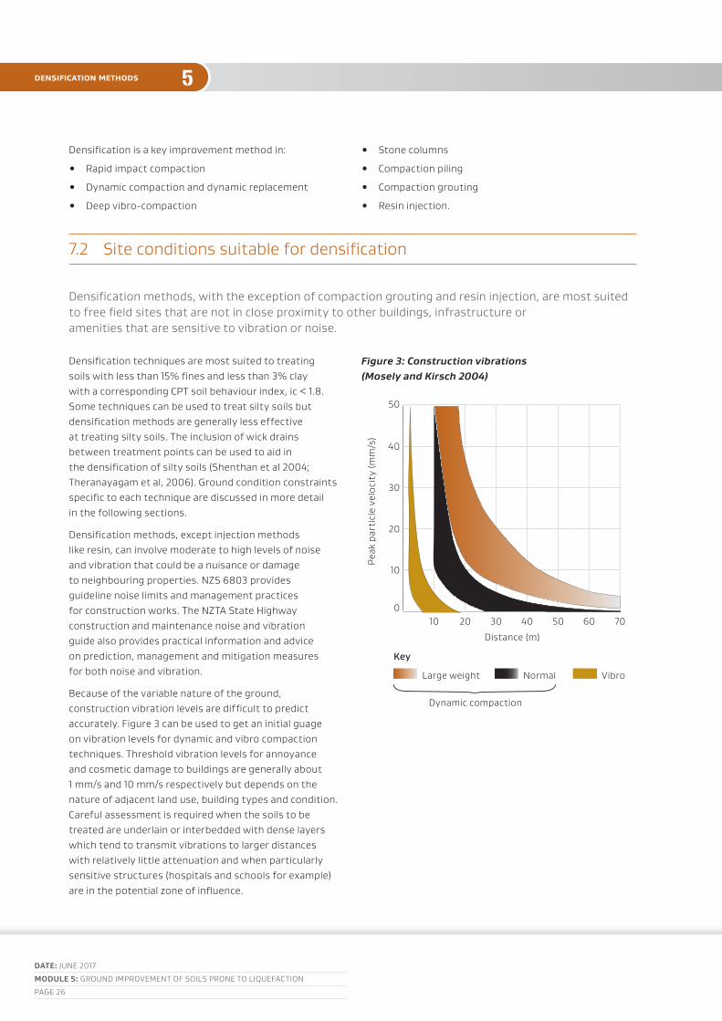
because of the variable nature of the ground, construction vibration levels are difficult to predict accurately. figure 3 can be used to get an initial guage on vibration levels for dynamic and vibro compaction techniques. threshold vibration levels for annoyance and cosmetic damage to buildings are generally about 1 mm/s and 10 mm/s respectively but depends on the nature of adjacent land use, building types and condition. careful assessment is required when the soils to be treated are underlain or interbedded with dense layers which tend to transmit vibrations to larger distances with relatively little attenuation and when particularly sensitive structures (hospitals and schools for example) are in the potential zone of influence.
Figure 3: Construction vibrations (Mosely and Kirsch 2004)
pea
k pa
rtic
le v
eloc
ity
(mm
/s)
50
40
30
20
10
010 20 30 40 50 60 70
distance (m)
Key large weight normal vibro
dynamic compaction
DATE: junE 2017
MoDulE 5: Ground ImprovEmEnt of SoIlS pronE to lIquEfactIon
paGE 27
5 densification methods
7.3 design considerations
the effectiveness of densification techniques is highly dependent on the fines content of the soils and the variability of the ground conditions to be treated. a comprehensive investigation should be undertaken to assess soil conditions and in particular, the fines content, location and extent of silt and clay layers at a site. the cpt should not be relied upon as the sole method for assessing the fines content of the soil.
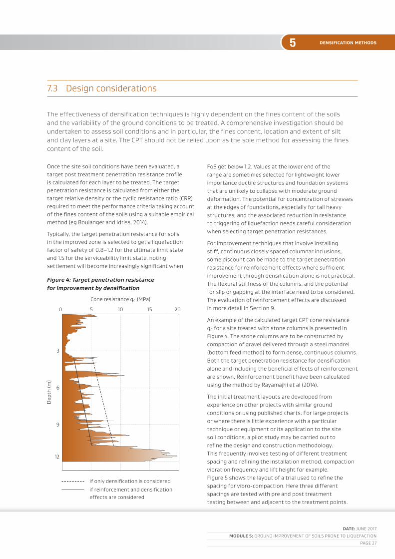
once the site soil conditions have been evaluated, a target post treatment penetration resistance profile is calculated for each layer to be treated. the target penetration resistance is calculated from either the target relative density or the cyclic resistance ratio (crr) required to meet the performance criteria taking account of the fines content of the soils using a suitable empirical method (eg boulanger and Idriss, 2014).
typically, the target penetration resistance for soils in the improved zone is selected to get a liquefaction factor of safety of 0.8–1.2 for the ultimate limit state and 1.5 for the serviceability limit state, noting settlement will become increasingly significant when
foS get below 1.2. values at the lower end of the range are sometimes selected for lightweight lower importance ductile structures and foundation systems that are unlikely to collapse with moderate ground deformation. the potential for concentration of stresses at the edges of foundations, especially for tall heavy structures, and the associated reduction in resistance to triggering of liquefaction needs careful consideration when selecting target penetration resistances.
for improvement techniques that involve installing stiff, continuous closely spaced columnar inclusions, some discount can be made to the target penetration resistance for reinforcement effects where sufficient improvement through densification alone is not practical. the flexural stiffness of the columns, and the potential for slip or gapping at the interface need to be considered. the evaluation of reinforcement effects are discussed in more detail in Section 9.
an example of the calculated target cpt cone resistance qc for a site treated with stone columns is presented in figure 4. the stone columns are to be constructed by compaction of gravel delivered through a steel mandrel (bottom feed method) to form dense, continuous columns. both the target penetration resistance for densification alone and including the beneficial effects of reinforcement are shown. reinforcement benefit have been calculated using the method by rayamajhi et al (2014).
the initial treatment layouts are developed from experience on other projects with similar ground conditions or using published charts. for large projects or where there is little experience with a particular technique or equipment or its application to the site soil conditions, a pilot study may be carried out to refine the design and construction methodology. this frequently involves testing of different treatment spacing and refining the installation method, compaction vibration frequency and lift height for example. figure 5 shows the layout of a trial used to refine the spacing for vibro-compaction. Here three different spacings are tested with pre and post treatment testing between and adjacent to the treatment points.
Figure 4: Target penetration resistance for improvement by densification
cone resistance qc (mpa)
0 5 10 15 20
dep
th (m
)
3
6
9
12
if only densification is considered
if reinforcement and densification effects are considered

DATE: junE 2017
MoDulE 5: Ground ImprovEmEnt of SoIlS pronE to lIquEfactIon
paGE 28
5densification methods
Figure 5: Example of a stone column field trial
cone
res
ista
nce
q s (m
pa)
25
20
15
10
5
500 1 2 3 4 5 6 7 8 9 10
Grid area a (m2)
7.4 design verification
verification testing involves carrying out penetration testing of the soil equidistant between treatment points and comparison with measurements before treatment and against target penetration values. the factor of safety against liquefaction may be calculated directly using the measured post treatment penetration resistance.
the importance of the overall stiffness of the ground improvement system was evident in the christchurch Ground Improvement trials (Eqc, in press). In these trials, cross-hole shearwave velocity measurements were taken to assess the improved stiffness from ground improvement. one of the advantages with cross-hole shearwave velocity measurement is that it can measure the overall stiffness of the improved zone accounting for both the stiffness of the inclusions and the natural ground. cross-hole shearwave velocity measurement is a specialist skill and needs further development before it can be used as routine verification of ground improvement but is a promising method for verification of the reinforcing effects of ground improvement.
there can be some delay between treatment and the dissipation of excess pore pressures generated during construction so verification of effectiveness may not be confirmed for some weeks after treatment. Experience in christchurch has shown that the full degree of improvement is often not realised for at least a week after treatment and sometimes up to three weeks after treatment.
the compaction process can affect the ratio of cpt sleeve friction to cone resistance. Where the cpt is used to verify treatment, pre-treatment values of the soil behaviour index should be used in the evaluation of the liquefaction factor of safety for the improved ground.
Sand
0.06 2.0
Key
b=0.2 – 0.4
compaction probe pre-penetration test post-penetration test
a
(1+b)=a
(1+2b)-a
a/si
n60
°
3 x
a/3
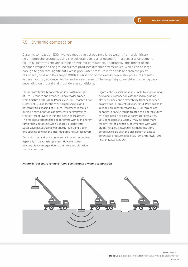
DATE: junE 2017
MoDulE 5: Ground ImprovEmEnt of SoIlS pronE to lIquEfactIon
paGE 29
5 densification methods
7.5 dynamic compaction
dynamic compaction (dc) involves repetitively dropping a large weight from a significant height onto the ground causing the soil grains to rearrange and form a denser arrangement. figure 6 illustrates the application of dynamic compaction. additionally, the impact of the dropped weight on the ground surface produces dynamic stress waves, which can be large enough to generate significant excess porewater pressure in the soils beneath the point of impact (Idriss and boulanger 2008). dissipation of the excess porewater pressures results in densification, accompanied by surface settlement. the drop height, weight and spacing vary depending on ground and groundwater conditions.
tampers are typically concrete or steel with a weight of 5 to 35 tonnes and dropped using crawler cranes from heights of 10–40 m. (moseley, 2004; Schaefer, 1997; lukas, 1995). drop locations are organised in a grid pattern with a spacing of 4–15 m. treatment is carried out in a series of passes of different energy levels to treat different layers within the depth of treatment. the first pass targets the deeper layers with high energy tamping in a relatively widely spaced grid pattern. Successive passes use lower energy levels and closer grid spacing to treat the intermediate and surface layers.
dynamic compaction is known to be fast and economic, especially in treating large areas. However, it has obvious disadvantages due to the noise and vibration that are produced.
figure 7 shows soils most amenable to improvement by dynamic compaction categorised by grading, plasticity index and permeability from experience on previous dc projects (lukas, 1995). pervious soils in Zone 1 are most treatable by dc. Intermediate deposits in Zone 2 can be treated to a limited extent with dissipation of excess porewater pressures. Silty sand deposits (Zone 2) may be made more readily treatable when supplemented with wick drains installed between treatment locations before dc to aid with the dissipation of excess porewater pressure (dise et al, 1994; andrews, 1998; thevanayagam, 2006).
Figure 6: Procedure for densifying soil through dynamic compaction

DATE: junE 2017
MoDulE 5: Ground ImprovEmEnt of SoIlS pronE to lIquEfactIon
paGE 30
5densification methods
treatment is usually effective only in the upper 5–7 m of the deposit for 8–15 t weights, but treatment to greater depth is possible with heavier weights. It is less effective for soils with fines content greater than about 15% or granular deposits interbedded with layers of silt and may be ineffective for soils with more than 25% fines Grading limits for soils suitable, marginally suitable and unsuitable are given in figure 7.
the effective depth of treatment is related to the ground conditions and the energy input and is often expressed as d = 2(WH)0.5, where d is the effective depth of treatment, W is the weight of the tamper, H is the drop height and α is an efficiency factor that typically ranges between 0.4 and 0.6.
there are no detailed analytical procedures available to analyse the effects of field dynamic compaction operational parameters and soil conditions to determine the densification and the degree of improvement achievable in the field. current practice relies mainly on field pilot tests, and past experience based on case histories. Initial estimates of fall height, spacing between drop locations, number of drops and wait times between drops can be estimated using the methods described in Elias et al (2006), thevanayagam et al (2006), jGS (1998), and lukas (1995).
It is common practice to provide a layer of free draining granular material on the ground surface, 600–2000 mm thick. this layer acts as an ‘anvil’ to help transfer the high stresses imparted by the drop weight into the insitu soils. In weak saturated soils, the granular material can be driven to depths of up to about four metres to form large diameter columns of stone. Strictly speaking, this is termed dynamic replacement but the principle and equipment used for construction are similar to dc.
for dynamic compaction, measurement of the energy being delivered to the ground, the sequence and timing of drops, as well as ground response in the form of crater depth and heave of the surrounding ground are important quality control parameters. Similarly, the location of the water table and presence of surface ‘hard pans’ could greatly affect the quality and outcome of the densification process. Groundwater pressures should be monitored throughout the process and compared to baseline data.
dynamic compaction was used to treat potentially liquefiable soils beneath the te papa museum, Hutt valley Wastewater treatment plant and mobil oil tank farm in Wellington and for the improvement of liquefiable soil at bridge sites along SH1 between mcKays crossing and peka-peka north of Wellington.
Figure 7: Soils suitable for dynamic compaction
% r
etai
ned
by w
eigh
t
0
u.S. sieve numbers
4 40 200
Key
Zone 1 Soils suitable for improvementt withd dynamic compaction. pervious soils pI = 0 k > 10-5 m/s
Zone 2 maybe improved with multiple passes. Semi-pervious soils 0 < pI < 8 10-5 > k > 10-8 m/s
Zone 3 dynamic compaction not recommended. Imervious soils pI > 8 k < 10-5 m/s
20
40
60
80
1001 0.1 0.01 0.001
Grain size (mm)
Gravelcourse medium fine
Silt or claySand
Zone 1 Zone 2 Zone 3

DATE: junE 2017
MoDulE 5: Ground ImprovEmEnt of SoIlS pronE to lIquEfactIon
paGE 31
5
7.6 vibro-compaction
treatment by deep vibro-compaction involves inserting a probe into the ground to apply primarily horizontal vibrations in a square or triangular grid across the site. the vibratory energy reduces the inter-granular forces between the soil particles, allowing them to move into a denser configuration, typically achieving a relative density of 70 to 85%. the treated soils have increased density, uniformity, friction angle and stiffness.
various methods and plant have been developed for vibro compaction to suit different site conditions. the most common type of probe is the vibroflot, a cylindrical steel tube with a diameter typically between 300 and 500 mm containing an eccentric weight linked to a motor. the length and weight of vibroflots typically vary between 3 and 4.5 m and 1500–4500 kg respectively.
figure 9 shows the vibro-compaction process. the vibrator is typically suspended from a crawler crane and lowered vertically into the soil under its own weight. penetration is usually aided by water jets (wet method) and compressed air. after reaching the bottom of the treatment zone, the soils are densified in lifts as the probe is extracted. the probe is installed and then retracted in a square or triangular grid pattern with a grid spacing typically between 1.2 and 2.5 m. conical depressions that form at the surface as the ground is densified are filled with imported aggregate that is added around the probe at the surface during treatment. typical treatment depths range between 5–15 m, but vibro compaction has been performed to depths as great as 35 m.
densification by vibro-compaction relies on the soil particles rearranging under vibraton and gravity into a more dense state. the degree of compaction attainable depends on the grain shape, soil grading and the probes vibration intensity. vibro compaction is most suited for the treatment of sands with low fines content, typically less than 12% fines and less than 2% clay. figure 8 shows the particle size distribution limits that are most suitable to vibro-compaction. very hard or cemented layers within the soil profile may need to be pre-bored to allow penetration of the vibrator to treat loose layers.
vibrations may be a nuisance to neighbouring properties but are generally less than those from impact methods like dynamic compaction. turbid water from the wet vibro-compaction method of installation needs to be contained and sediment removed before being disposed of. vibro compaction can disperse ground or groundwater contaminants and alternative methods of treatment should be found if there is a contamination hazard at the site.
Figure 8: Ground conditions suitable vibro-compaction (Elias et al 2006)
% r
etai
ned
by w
eigh
t
100Key
Gravel
Sand
Silt
clay
vibro replacement
vibro compaction
80
60
40
20
0100 000 10 000 1 000 0 100 0.010 0 002 0 001
Grain size (mm)
densification methods
Soils suitable for vibro-compaction
Soils suitable for vibro-replacement

DATE: junE 2017
MoDulE 5: Ground ImprovEmEnt of SoIlS pronE to lIquEfactIon
paGE 32
5
Figure 9: Vibro-compaction using a vibroflot
the degree of compaction generally decreases with increasing distance from the probe. Establishment of the treatment spacing, frequency of the vibrator and advancement and withdrawal rates is based on past experience or a field pilot study. Spacing of the treatment grid can initially be estimated from figure 10. other useful charts for determining a treatment spacing are in jGS 1998.
the supplementary aggregate added to fill the cavity and depression formed at each treatment point needs to fall freely in water to the base of the probe. particle size recommendations based on settling rate and experience are given by Elias et al (2006).
vibro-replacement rigs can be fully instrumented with an on-board computer to monitor specific parameters. monitoring these parameters allows the operator to correct any deviations in real-time during the construction process to keep the stone column within project specifications. data from the data acquisition (daq) system such as amperage and lift rate are recorded and displayed in real-time alongside specified target values on an in-cab monitor. the ‘free hanging’ amperage as well as the amperage developed during construction are strong indicators of the likely success of the densification effort. on some rigs it is possible to monitor the pressure and quantity of the flushing media with time for each treatment location.
the imported aggregate should be sampled randomly and the particle size distribution measured and compared to the specified envelope. the quantity of aggregate used at each treatment point should also be recorded.
densification methods
Figure 10: Level of improvement vs area replacement ratio (Barksdale and Bachus 1983)
area replacement ratio (%)
rel
ativ
e de
nsit
y (%
)
29.5 14.5 9.8 7.3 5.9 4.9 4.2
(n1)
60 in
san
d co
rrel
atio
n
afte
r tok
imat
su a
nd S
eed
(198
7)
90 40
80 30
70 22
60 16
50 111.9 3.7 5.6 7.4 9.3 11.2 13.0
area per compaction probe (m2)
Key
Silty sand (5–15% silt) uniform, fine to medium sand (clean) Well-graded clean sand
ar=ac a
a tributary
ac Stone column

DATE: junE 2017
MoDulE 5: Ground ImprovEmEnt of SoIlS pronE to lIquEfactIon
paGE 33
5 densification methods
7.7 Stone columns
In the stone column ground improvement, columns of dense stone are compacted into the ground in either a triangular or square grid across the site. the columns are typically spaced 1.5 m–4 m apart and have a diameter of 0.6 m–1.2 m. the depth of improvement is typically 4 m–15 m but soils as deep as 30 m have been treated using this method. Generally the fill material consists of crushed coarse aggregates of various sizes, with the particle size distribution prescribed. crushed recycled concrete can also be used to construct the columns.
a variety of granular column construction methods have been developed out of the need to adapt the method to different site and ground conditions and to make use of locally available plant. In new Zealand, stone columns have been constructed using the vibro-replacement method (using a vibroflot), by driving a casing and compacting gravels out of the base of the casing and with displacement augers, modified to compact aggregate delivered to the bottom of the column through the casing. construction of stone columns using the driven casing method is depicted in figure 11.
Stone columns are most effective at treating sands with less than 20% fines but can be used effectively to treat silty sands and sandy silts. Wick drains pre-installed between the stone columns improve the densification of silty soils (thevanayagam et al. 2006, rollins et al 2009).
the primary mechanism for improvement is densification of the soil between the columns by displacement and compaction. depending on the construction method, installation of a grid of granular columns can also improve liquefiable soil deposits by increasing the insitu lateral stress, replacing the liquefiable insitu soil with non-liquefiable material, reinforcing the original ground with stiffer columns of fill material and providing drainage paths for the relief of excess porewater pressure (munfakh et al, 1987; Sondermann and Wehr, 2004).
the maximum spacing between columns to obtain the required improvement depends strongly on the method of installation. Spacing of columns are based on past experience with similar construction techniques and ground conditions or published relationships between degree of improvement and area of treatment per column, see figure 10 and jGS (1998). pilot studies can be used to optimise column spacing and construction method.
because of the uncertainty regarding the effectiveness of drainage and increased lateral stress, these mechanisms are usually ignored in the design of stone columns. the benefit of improved overall stiffness of the improved zone was evident in the Eqc ground
improvement trials. for bottom feed methods that form continuous dense and stiff stone columns, account can be made for the benefit of reinforcement where it proves impractical to densify the ground to the extent needed to meet the performance requirements. from numerical simulations, rayamajhi et al (2016) concluded that the reinforcement effects of stone columns can be greatly over estimated by methods based on the assumption of shear strain compatibility (eg baez and martin, 1993). the method proposed by rayamajhi et al (2014) can be used to assess the benefits of reinforcement. Shear stress relief from reinforcement effects of stiff columnar inclusions are discussed further in Section 12.
to avoid the migration of fines into the columns with the dissipation of excess porewater pressure during or after an earthquake and the resulting subsidence and reduction in stiffness and permeability of the column, the grading of the aggregate should be designed to filter the surrounding soil. criteria for filtration are provided in nYSdot (2013). the stone should be well graded, angular sound stone. although drainage is not depended on, the fines content of the aggregate should be less than 8%.
Figure 11: Stone column construction using the driven casing method
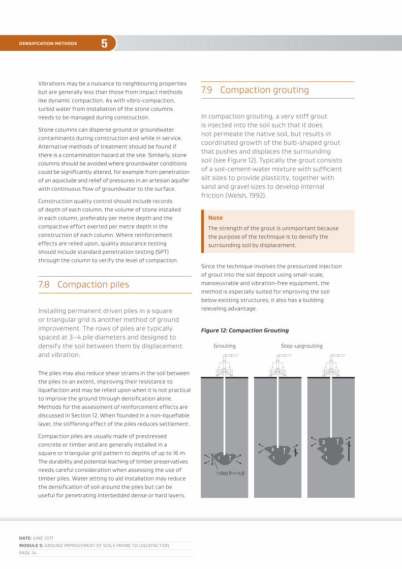
DATE: junE 2017
MoDulE 5: Ground ImprovEmEnt of SoIlS pronE to lIquEfactIon
paGE 34
5
vibrations may be a nuisance to neighbouring properties but are generally less than those from impact methods like dynamic compaction. as with vibro-compaction, turbid water from installation of the stone columns needs to be managed during construction.
Stone columns can disperse ground or groundwater contaminants during construction and while in service. alternative methods of treatment should be found if there is a contamination hazard at the site. Similarly, stone columns should be avoided where groundwater conditions could be significantly altered, for example from penetration of an aquiclude and relief of pressures in an artesian aquifer with continuous flow of groundwater to the surface.
construction quality control should include records of depth of each column, the volume of stone installed in each column, preferably per metre depth and the compactive effort exerted per metre depth in the construction of each column. Where reinforcement effects are relied upon, quality assurance testing should include standard penetration testing (Spt) through the column to verify the level of compaction.
7.8 compaction piles
Installing permanent driven piles in a square or triangular grid is another method of ground improvement. the rows of piles are typically spaced at 3–4 pile diameters and designed to densify the soil between them by displacement and vibration.
the piles may also reduce shear strains in the soil between the piles to an extent, improving their resistance to liquefaction and may be relied upon when it is not practical to improve the ground through densification alone. methods for the assessment of reinforcement effects are discussed in Section 12. When founded in a non-liquefiable layer, the stiffening effect of the piles reduces settlement .
compaction piles are usually made of prestressed concrete or timber and are generally installed in a square or triangular grid pattern to depths of up to 16 m. the durability and potential leaching of timber preservatives needs careful consideration when assessing the use of timber piles. Water jetting to aid installation may reduce the densification of soil around the piles but can be useful for penetrating interbedded dense or hard layers.
7.9 compaction grouting
In compaction grouting, a very stiff grout is injected into the soil such that it does not permeate the native soil, but results in coordinated growth of the bulb-shaped grout that pushes and displaces the surrounding soil (see figure 12). typically the grout consists of a soil-cement-water mixture with sufficient silt sizes to provide plasticity, together with sand and gravel sizes to develop internal friction (Welsh, 1992).
Note
the strength of the grout is unimportant because the purpose of the technique is to densify the surrounding soil by displacement.
Since the technique involves the pressurized injection of grout into the soil deposit using small-scale, manoeuvrable and vibration-free equipment, the method is especially suited for improving the soil below existing structures; it also has a building releveling advantage.
Figure 12: Compaction Grouting
Grouting Step-upgrouting
1
1 step (h = 0.3)
1
2
1
23
densification methods

DATE: junE 2017
MoDulE 5: Ground ImprovEmEnt of SoIlS pronE to lIquEfactIon
paGE 35
5 densification methods
However, it has some disadvantages; for example, stabilisation of near surface soils is generally ineffective due to the fact that the overlying restraint is small (ie low confining pressures) and the grouting pressures can heave the ground surface rather than densify the soil. results from the Eqc ground improvement trials indicated that shallow treatment using low mobility grout tended to dilate soils for ground profiles with interbedded sand and silty soils as the grout tended to spread through soft layers because of the low confining pressures, actually increasing the potential for liquefaction.
because grout is typically injected in stages from the bottom up, at each stage a stopping criteria of grout volume, pressure, or heave is followed before proceeding with the next stage. usage of grout casing with less than 50 mm in internal diameter should be avoided as it could cause detection of high back pressures before sufficient grout is injected. over injection of grout in a primary phase may lead to early ground heave and may diminish densification effectiveness. Spacing and sequence of the grout points may also affect the quality of densification or ground movement achieved.
compaction grouting requires the verification of slump and consistency of the mix, as well as careful monitoring of grout volumes, injection pressures, and ground movement at the surface or next to sensitive structures. critical projects also monitor porewater pressure and deep ground heave (borros points) that develop during the compaction grouting procedures.
7.10 resin injection
resin injection primarily provides liquefaction mitigation as a result of densification of the soil from an aggressively expanding polyurethane resin. Secondary mechanisms of improvement from increased composite stiffness and horizontal stress increases may also be present (traylen et al, 2017).
Injection tubes are driven into the ground at regular intervals, through which low viscosity resin materials (which have been mixed at specific pressures and temperatures) are pumped at controlled pressures into the soil matrix. Either ‘top down’ or ‘bottom up’ methods can be employed. In a typical ‘bottom up’ installation the tube is withdrawn either in set stages with set volumes of material injected at each stage, or it is slowly withdrawn at a uniform rate, with set volumes of material being injected per unit length of withdrawal.
the resin penetrates the soil mass along pre-existing planes of weakness or through fracturing of the soil mass (it also permeates the soil mass to a limited extent; depending on the porosity of the soil). the resin mix chemically reacts soon after injection, rapidly expanding to many times its original volume, and changing from a fluid form to a solid one. this expansion of the injected material in the soil matrix results in densification of the adjacent soils.
Figure 13: Hand-exhumed resin veins (left) and hydro-exhumed resin veins (right)

DATE: junE 2017
MoDulE 5: Ground ImprovEmEnt of SoIlS pronE to lIquEfactIon
paGE 36
5densification methods
unlike compaction grouting (which uses a high viscosity medium), the low viscosity expanding resin injection process typically results in a ‘veining’ of expanded material distributed through the soil mass as dykes, sills or networks of sheets or plates, typically tens of millimetres thick (refer to figure 13).
research trials and also commercial application of this technology have shown increases in cpt cone resistance of 25–100% being achieved, depending
on the soil type being treated. as with most densification methods, the best results are achieved in clean sands (ie Ic<1.8) but good results are also achieved in silty sands up to an Ic of at least 2.0, and densification is still noted in soils with even higher silt contents.
although applicable to cleared sites, the particular advantage of resin injection is its suitability for use beneath existing structures (see figure 14).
Figure 14: Installing injection tubes, injecting resin inside a supermarket

DATE: junE 2017
MoDulE 5: Ground ImprovEmEnt of SoIlS pronE to lIquEfactIon
paGE 37
5 solidification methods
8 soLIdIfICatIon methods
8.1 outline
Solidification involves either insitu mixing of cementitious or other additives into the soil or filling the voids with a reagent resulting in the soil particles being bound together. this will prevent the development of excess porewater pressure, preventing the occurrence of liquefaction. the strength and stiffness of the soil are increased by the stabiliser, and thus the solidified ground can mitigate differential subsidence.
Solidification methods are advantageous because installation is relatively quiet and the techniques induce relatively small vibrations as compared to compaction methods. these are important considerations for the improvement of sites with adjacent infrastructure or inhabitants that could be affected by noise and vibration from densification techniques. their disadvantage is the relatively high cost as compared to compaction methods.
there is a high degree of confidence that liquefaction will be prevented within the zone of solidification and when the full depth of liquefiable soil is treated, liquefaction effects can be eliminated entirely. another advantage of solidification is that the soils usually do not need to be treated outside the perimeter of the building although this is not easy to control for permeation grouting. this can be an important issue for buildings near to the section legal boundary.
8.2 techniques for solidification
typical methods include:
• Soil mixing
• jet grouting
• permeation grouting.
With jet grouting and columnar deep soil mixing techniques, either the entire footprint can be solidified by overlapping the columns or the improved area can be partially solidified in a grid of individual columns or to form a lattice of intersecting walls that reinforce the ground. partial solidification to mitigate liquefaction by reinforcement is discussed in Section 12.
DATE: junE 2017
MoDulE 5: Ground ImprovEmEnt of SoIlS pronE to lIquEfactIon
paGE 38
5
8.3 Site conditions suitable for solidification
Solidification techniques, in general, can be used to treat a wide range of soil types. Some organic soils may not gain appreciable strength from mixing with cement and soils containing large inclusions such as gravels or even large shell are not readily treatable with jet grouting. figure 15 shows the soils suitable for different solidificaiton techniques.
jet grouting and permeation grouting use comparatively compact and low vibration equipment and are suitable methods for treating the ground below existing structures or on sites with limited space where remediation is difficult using other methods. deep soil mixing is limited to use on open sites with access for drilling machinery.
permeation grouting is more suited to moderately permeable soil and relatively homogeneous ground profiles. With layered soil profiles there can be a tendency for the grout to spread through more permeable or weaker layers although this is can be combated with multiple grouting phases. It may be possible to treat some silty soils with permeation grouting with expensive silicate grouts.
near waterways there is a risk of contamination with permeation grouting a loss of lateral confinement with jet grouting. this risk can be mitigated with sheet piles or other measures to protect waterways.
8.4 design considerations
the soil-cement materials can have a wide range of unconfined compressive strengths, depending on the homogeneity of the mixing or grouting process, the degree of compaction imparted by the solidification technique, the amount of cementitious material used and the insitu soil characteristics (Kitazume and terashi, 2013; porhaba, 2000). the unconfined compressive strength (ucS) of the overall block needs to be characterised using past experience and laboratory testing and a design value adopted.
In the early stages of the project, laboratory tests are undertaken to ascertain the constraints that the soil characteristics may have on the ground treatment and to characterise the level of treatment that can be expected from application of different binders or different binder rates. for soil mixing and jet grouting, each layer to be treated can be mixed with a range of binders and dosages in the laboratory to ascertain the soils reactivity and strength gain with different volumes of additive.
laboratory scale tests do not always reflect field experience as the nature and efficiency of mixing in the field will affect the stiffness and strength of the solidified material. porhaba (2000) discusses selection of a ucS for design.
consistency of column diameter, tolerances on drilling position and verticality and the strength gain between installation of successive jet grout or dSm columns needs to be considered when selecting a column spacing and
Figure 15: Range of applicability of soil grouting techniques
pass
ing
by w
eigh
t (%
)
100Gravel Sand Silt clay
60
20
60 2.0 0.06 0.002
particle size (mm)
solidification methods
permeation grouting/
chemical grounting
jet grouting
cement slurry grouting
deep soil mixing

DATE: junE 2017
MoDulE 5: Ground ImprovEmEnt of SoIlS pronE to lIquEfactIon
paGE 39
5 solidification methods
planning the timing of installation of each column. this is especially important for jet grouting as the columns effectively cannot be formed if the drill head penetrates into an adjacent hardened column.
for permeation grouting the permeability of the soils in the horizontal and vertical directions needs to be assessed in detail as this has the greatest impact on the effectiveness of permeation grouting. permeability of the ground profile as a whole can be investigated with pumping tests and individual layers can be tested with down hole testing or in the laboratory on undisturbed samples.
jet grouting and soil mixing loosen the ground or temporarily turn it into a slurry during construction. this can destabilise, or cause subsidence of existing building foundations if they are near to the area of treatment. the location of columns and the timing between different stages of the construction works need to be planned to avoid instability or unacceptable subsidence of existing foundations. permeation grouting is done under high pressure and can heave the ground and foundations above.
underground utilities may need to be relocated or protected prior to treatment. permeation grouting and jet grout can fill sewer and stormwater pipes through any open joints or cracks. there can be large differential movements at the interface between the solidified ground and surrounding liquefied soils that can severely damage underground services
cement stabilised soils are brittle and have low strength in tension. the solidified ground should be designed to avoid concentration of strains at large widely spaced cracks that could cause abrupt differential settlement of the structure. this is especially important where only partial depth of soils prone to liquefaction are treated. a granular layer placed over the cemented fill can smooth out abrupt changes in level or grade beneath shallow foundations.
Figure 16: Deep soil mixing process
8.5 design verification and quality control
verification of solidification methods involves coring of the treated area and undertaking unconfined compression tests on samples of the core to confirm the extent and homogeneity of improvement and the strength and stiffness of the solidified soil. areas of overlap and the zone equidistant between columns as well the centre of columns should be sampled.
the binders are controlled for quality by checking consistency as measured by specific gravity. this is generally checked with mud balance or hydrometer devices. pumping pressures and rates are designed to achieve production and strength requirements of the product.
8.6 Soil mixing
Soil mixing involves agitating and mixing stabilizing material such as cement in sandy soil and solidifying the soil. a variety of plant has been developed for soil mixing.
for mass stabilisation, a rotating drum cutter attached to an excavator arm can be used to mix the soil with the stabilising agent. this method is generally limited to treatment depths of about 6 m.
other methods use rotating augers or blades attached to rods to mix soils in vertical columns up to depths of 30 m or more. this technique is commonly referred to as deep soil mixing (dSm) or deep mixing method (see figure 16).
cutting heads have also been attached to directional drilling plant to mix soils in horizontal beams below existing structures (Wansbone and van ballegooy, 2015).

DATE: junE 2017
MoDulE 5: Ground ImprovEmEnt of SoIlS pronE to lIquEfactIon
paGE 40
5solidification methods
8.7 jet grouting
In jet grouting, high-pressure jets of air and/or water and grout are injected into the native soil in order to break up and loosen the ground and mix it with thin slurry of cementitious materials.
In essence, it is not truly grouting but rather a mix-in-place technique to produce a soil-cement material. depending on the application and soils to be improved, different kinds of jet are combined by using single fluid system (slurry grout jet), double fluid system (slurry grout jet surrounded by an air jet) and triple fluid system (water jet surrounded by an air jet, with a lower grout jet). the process can construct grout panels, full columns or anything in between (partial columns) with a specified strength and permeability.
construction of jet grout columns involves drilling to the base of the column then mixing a cement slurry into the soil insitu with rotating high pressure jets that are located just above the drill head as the drill string is brought to the surface. the process is illustrated in figure 17. the double and triple fluid processes are capable of producing larger diameter but generally weaker columns compared to the single fluid process. column diameters of up to 8 m are possible in dispersive soils with specialist equipment other advantages of jet grouting are that treatment can be for targeted layers only and the ability to treat multiple depths at any location.
Figure 17: Jet grout construction process
8.8 permeation grouting
permeation grouting, sometimes called chemical grouting, is a technique that transforms clean gravel and sands into hardened soil mass by injecting cement or other grouting materials that permeate and fill the pore space. the hardened grout improves the native soil by cementing the soil particles together and filling the voids in between (minimising the tendency of the soil to contract during shearing). the treated soil has increased stiffness and strength, and decreased permeability.
because of its minimal disturbance to the insitu soil, it is an effective method in treating liquefiable deposits adjacent to existing foundations or buried structures. this method is most suited to treating moderate permeability liquefiable gravels and sands. Some grouts are toxic in their liquid form and the spread of the grout is not easily controlled. the risk of contamination groundwater and nearby waterways needs careful consideration.
permeation grouting is typically expensive compared to other methods and therefore it is not discussed in detail here. further information can be found in the reference texts.

DATE: junE 2017
MoDulE 5: Ground ImprovEmEnt of SoIlS pronE to lIquEfactIon
paGE 41
5 reinforcement methods
9 reInforCement methods
9.1 outline
When saturated sand deposits are sheared during seismic loading, excess porewater pressure is generated reducing the stiffness and strength of the soil and increasing strains. the aim of reinforcement is to reduce shear deformation in the ground during an earthquake to mitigate the development of excess porewater pressures. the increased composite strength of the reinforced ground also mitigates ground deformation and subsidence of the structure if liquefaction were to occur. these principles are illustrated in figure 18 and 19.
reinforcement of the ground involves either construction of a:
• lattice of intersecting walls to form containment cells, or
• a grid of closely spaced stiff vertical columns.
typical layouts for lattice and isolated pile reinforcement arrangements are shown in figure 19.
open grid systems are relatively flexible compared to lattice systems and do not offer the same
protection against the migration of excess pore water pressures or confinement of liquefied soils as a lattice with continuous perimeter walls. because of the greater redundancy of lattice structures, they are a much more reliable method of reinforcement than grids of isolated piles.
Soil reinforcement is typically used to treat soils up to a depth of 20 m but greater depths are possible with some methods of construction and specialised equipment.
Figure 18: Principle of reinforcement and containment:
a) suppression of shear deformation in ground during earthquake
b) suppression of lateral flow of ground after liquefaction (after JGS 1998)
large deformation
Small deformation
Suppression of lateral deformation of the ground
Earthquake motion Earthquake motion
Wall
DATE: junE 2017
MoDulE 5: Ground ImprovEmEnt of SoIlS pronE to lIquEfactIon
paGE 42
5
Figure 19: General arrangements of structural elements for lattice and isolate pile reinforcement
Lattice Pile
the advantages of reinforcement are that it can be used for a range of ground conditions, including sites with silty soils and variable soils, construction vibration is typically small and, with the use of jet grouting, ground beneath existing structures and on sites with limited space can be treated to improve their seismic performance.
With lattice reinforcement, the lattice perimeter wall can often be placed below the perimeter of the building unlike most densification and drainage methods. this is advantageous for ground improvement beneath buildings constructed close to the legal boundary.
one disadvantage of reinforcement techniques is that there are no simple methods to verify the effectiveness of the reinforcement at mitigating shear strain in the soil between the reinforcement elements. compared with densification and drainage techniques, reinforcement methods are typically more costly.
9.2 techniques for reinforcement
the lattice structures can be formed using overlapping dSm or jet grout columns, overlapping continuous flight auger (cfa) piles or other contiguous pile and diaphragm wall techniques.
piles within an isolated grid can be constructed using dSm or jet grout techniques, driven timber or precast concrete piles, or with conventional bored concrete piles, cfa or displacement auger concrete piles. With displacement auger piles and driven piles, there is added benefit of densification of soils between the columns. jet grout columns can be reinforced by plunging a cage into the wet slurry similar to the reinforcement of cfa piles.
9.3 Site conditions suitable for reinforcement
reinforcement can be used to treat most soil types including the treatment of sites with cohesive soils interbedded within liquefiable layers.
methods that involve the mixing of additives with insitu soils (dSm and jet grouting) may not be suitable for sites with organic layers that are thicker than the diameter of the reinforcing elements, particularly layers of fibrous peat. the treatment of gravels or soils containing dense layers, cobbles and other large inclusions can also be problematic. further guidance on the suitability of ground conditions for dSm and jet grouting is provided in Section 11.
9.4 design considerations
the spacing and sizing of reinforcement elements are typically based on methods developed from the results of numerical and centrifuge simulations of simplified soil profiles (nguyen, 2013; rayamajhi, 2014) or, for larger projects, numerical analysis with the site specific conditions.
Early methods to calculate the layout of soil reinforcement elements, by baez and martin (1993) for example, assumed that the soil and reinforcement elements deform purely in shear and that the shear strain in the soil is equal to the shear strain in the reinforcement (commonly referred to as shear strain compatibility). numerical and centrifuge studies (Goughnour and pestana, 1998; Green, 2008; oglan and martin, 2008; nguyen, 2013; rayamajhi, 2014, 2015) have since found that the assumption of shear strain compatibility may greatly overestimate the magnitude of strain relief in the soil between reinforcement elements.
reinforcement methods

DATE: junE 2017
MoDulE 5: Ground ImprovEmEnt of SoIlS pronE to lIquEfactIon
paGE 43
5 reinforcement methods
When designing the spacing of reinforcement elements, consideration needs to be given to the location of shallow foundations relative to the reinforcement elements. there may be some development of excess porewater pressure in soils between the reinforcement and having some footings directly supported on the reinforcement elements and others on the soil between the reinforcement should be avoided.
unreinforced concrete, dSm and jet grout columns are susceptible to brittle failure. the tension stresses and shear stress in structural elements for both static and earthquake loads including loads transferred from the building above need to be evaluated during design, especially for individual columns that rely on some degree of fixity in soils above or below liquefied layers. lattice structures have greater structural redundancy and limited cracking may be acceptable where the overall system remains ductile and structural integrity is not greatly reduced. refer to discussion on damage modelled in grid walls by namikawa et al (2007).
9.5 design verification
verification for deep soil mixing and jet grouting include confirmation of the consistency of mixing and pile diameter, the strength and stiffness of the columns.
for the construction of lattice structures using overlapping piles, the bond between adjacent piles needs to be verified. joints where one day’s work ends and another starts should be located in low stress areas.
9.6 lattice reinforcement
lattice reinforcement limits the horizontal squeeze of soils beneath shallow footings and prevents the migration of excess porewater pressures from adjacent liquefied soils. In many cases, the lattice need not extend far beyond the footprint of the building.
the effectiveness of lattice-type improvement to mitigate the development of excess porewater pressures in the soils contained within the cells of the lattice have been shown in numerical studies and centrifuge tests to be strongly dependent upon the grid spacing and the thickness and stiffness of the walls (bradley et al, 2013; Kitazume and takahashi, 2010; funahara et al 2012).
nguyen (2013) describes a simplified approach that can be used to calculate panel spacing and thickness for a given wall shear modulus. It is important to remember that this simplified approach is based on numerical simulations using a simplified model with lattice walls that fully penetrate the liquefiable layer. It does not consider the influence of external loads (eg from the building). project specific numerical analysis should be considered for projects with important, heavy or irregular structures.
Stresses within the walls and the potential for cracking can be assessed using the simplified methods proposed by nguyen (2013) or orouke and Goh (1997).
Installing a drainage blanket over the improved area and a perimeter subsoil drain through the crust around the outside of the improved area to intercept and relieve water pressure and prevent soil seepage erosion is prudent where the improved zone does not fully penetrate liquefied layers. this layer will also give a more even transfer of loads from the footings to the improved ground.

DATE: junE 2017
MoDulE 5: Ground ImprovEmEnt of SoIlS pronE to lIquEfactIon
paGE 44
5reinforcement methods
9.7 Stiff columnar reinforcement grids
the degree of strain relief and liquefaction mitigation from a grid of isolated reinforcement columns depends on:
• the spacing of the columns
• the stiffness and strength of the columns
• the degree of rotational fixity of the columns above and below potentially liquefiable soils
• the surface roughness of the reinforcing elements and magnitude of interface adhesion.
the reinforcement effect increases with increasing area replacement, increasing flexural stiffness of the individual columns, rotational fixity at the top or bottom of the columns, especially if the columns work in double bending, and a rough interface between the reinforcement columns and the surrounding soil.
With the relatively high uncertainty in the ability of grids of stiff individual columns to supress liquefaction or the development of significant excess porewater pressures, to give some redundancy to the system, columns should extend down to a competent non-liquefiable layer and the area of treatment should extend beyond the perimeter of the building a suitable distance to protect against lateral deformation of the ground near the edge of the building. a granular load transfer platform
and drainage blanket should be constructed across the top of the stiff pile reinforcement to relieve excess porewater pressures that develop in the soils between the piles during shaking and to distribute load between the building and the piles.
a grid of stiff columns are typically not suitable for mitigating lateral spreading unless the liquefiable layer is relatively thin, the piles are designed to cantilever from the underlying non-liquefiable layer and suitably reinforced for the bending and shear stress that will develop from the kinematic loading of the piles.
the simplified method based on dynamic numerical analysis of a pile through liquefied soil by rayamajhi (2014) can be used to design the pile grid layout and estimate tension stress in the piles. a more detailed assessment of the bending and shear in the piles can be made by calculating the profile of horizontal ground displacements for the improved ground by integration of the soil shear strains over its depth and applying these to a pile in a beam on spring analysis together with a contribution of building inertia. the procedure is described in module 4.

DATE: junE 2017
MoDulE 5: Ground ImprovEmEnt of SoIlS pronE to lIquEfactIon
paGE 45
5 drainage methods
10 draInaGe methods
10.1 outline
drainage can mitigate liquefaction potential in two respects:
1 drainage can desaturate potentially liquefiable soil, either by draw down of groundwater or gas entrainment.
2 alternatively, vertical gravel or prefabricated drains typically installed at 1–2 m intervals can be installed to allow the rapid dissipation of excess pore pressures generated during shearing preventing the condition of ru=1 or liquefaction developing. Excess porewater pressure generated by cyclic loading is dissipated by installing permeable drains within the deposit. these methods rely on two mechanisms to reduce damage due to liquefaction:
– delaying the development of excess pore water pressure due to earthquake shaking
– preventing the migration of high excess pore water pressure from untreated liquefied zones into non-liquefied areas (say underneath the structure) to prevent secondary liquefaction caused by porewater pressure re-distribution.
disadvantages of this method are that there is no easy way to verify the effectiveness of the drains in the field and, should liquefaction be triggered in an earthquake, the damage may be just as severe as if no drains were installed. furthermore, the spacing of the drains is sensitive to the permeability of the soil which is not readily measureable and often highly variable.

DATE: junE 2017
MoDulE 5: Ground ImprovEmEnt of SoIlS pronE to lIquEfactIon
paGE 46
5drainage methods
10.2 permanent dewatering
lowering the groundwater table increases the thickness of the non-liquefiable crust, and increases the effective stress for soils below the water table. If the water table is reduced to a level below the liquefiable soil layer, liquefaction is prevented because the absence of water makes the buildup of excess porewater pressure impossible (cox and Griffiths, 2010).
clearly, in order to retain effectiveness, it is necessary to maintain the low groundwater level in applying this method. therefore, at sites with virtually unlimited recharge areas and those requiring large estimated improvement, the use of this technique is typically too costly due to the maintenance associated with continual pumping and the deterioration of pumping efficiency over time.
However, at some sites where it is possible to lower the water table to a designated depth over a long period of time, ie permanent dewatering, this technique can be a good method to prevent liquefaction-induced damage to structures. for example, Yasuda (2015) reported the application of this technique to several sites in japan to improve the liquefiable soil of a large residential area. the studies indicated that the appropriate water table to prevent liquefaction damage to wooden houses is about 3 m below ground level. for this purpose, drain pipes and shallow wells were installed under roads and these were able to lower the water level under the houses.
Subsequent investigations indicated that porewater pressure decreased due to dewatering only at shallow depths. based on these studies in 2014, the japanese ministry of land, Infrastructure and transport (mlIt) published a guideline on how to apply this remediation concept (Yasuda, 2015). Koseki et al (2015) also reported a case study in japan where permanent dewatering was adopted as countermeasure against future liquefaction following the 2011 tohoku earthquake. using a network of drainage ditches constructed along the roads in the target area, plus installation of supplementary wells, the water table was lowered to 2.1 m below ground level.
Note
as a consequence of the increased effective stress due to dewatering, excessive settlement may occur due to consolidation of soft or loose layers at the site. therefore, to supplement the application, insitu monitoring and numerical analyses are recommended to predict the associated long-term ground settlement.

DATE: junE 2017
MoDulE 5: Ground ImprovEmEnt of SoIlS pronE to lIquEfactIon
paGE 47
5 drainage methods
10.3 vertical drains
vertical drains are typically installed either as column-like drains in a closely-spaced grid pattern or as backfill around underground structures to control the levels of maximum excess porewater pressure ratio during earthquake shaking. they can also be installed as wall-like or column-like perimeter drains around the perimeter of densified (treated) zones to isolate the migration of high excess porewater pressure from liquefied areas. In the installation of gravel drains, a casing with an auger inside is drilled into the ground down to the specified depth. crushed stone is then discharged into the casing and the gravel drain is formed by lifting the casing pipe.
artificial drains can be made of geosynthetic composites or piles with drainage functions. plastic drain consists of a plastic perforated pipe wrapped in geofabric to prevent clogging from soil particles. these can be easily installed; however, close spacing is usually required due to the limited capacity of each drain. the installation of prefabricated drains is illustrated in figure 20.
design charts for drains were initially developed by Seed and booker (1977) to control the maximum excess porewater pressure levels, but more recent design charts and analytical methods (eg Iai and Koizumi, 1986; pestana et al, 1997) provide better methods of taking into account various factors affecting the drain performance, such as the hydraulic properties of the drain and permeability and volumetric compressibility of the native soil.
drainage remediation methods are most suitable for use in sands with less than 5% fines. one of the greatest advantages of drains is that they induce relatively small horizontal earth pressures and can be installed with relatively low vibration during installation. therefore, they are suitable for use adjacent to sensitive structures. In the design of drains, it is necessary to select a suitable drain material that has a coefficient of permeability substantially larger than the insitu soils.
Since the insitu soils improved by this method remain in a loose condition, the method has obvious disadvantages when compared to compacted deposits, such as negligible ductility and significant residual settlement of the treated soils should liquefaction be triggered. It is effective only if it successfully promotes sufficiently rapid dissipation of pore pressures as to prevent the occurrence of liquefaction; if pore pressure dissipation is not sufficiently rapid during the relatively few critical seconds of the earthquake, this method does relatively little to improve post-liquefaction performance (Seed at al, 2003). thus, the method is usually combined with densification methods, ie the surrounding ground is compacted to some extent during the drain installation.
Where drainage is the primary mechanism of treatment, both the aggregate and geosynthetics (geotextiles, geofabrics, and geocomposites) must have the appropriate permeability to dissipate the build-up of porewater pressures induced during shaking. verification of the materials should be undertaken prior to construction. drainage aggregate should have particle size distribution (pSd) tests undertaken to confirm the grading of the material is suitable in terms of filtration and permeability. Similarly, geosynthetics need to be tested to confirm they have an appropriate porosity, which will allow the egress of water and retention of soils, strength and filtration properties.
Figure 20: Prefabricated vertical drains to mitigate liquefaction

DATE: junE 2017
MoDulE 5: Ground ImprovEmEnt of SoIlS pronE to lIquEfactIon
paGE 48
5ground improvement for residential construction
11 Ground ImProvement for resIdentIaL ConstruCtIon
In response to the 2010–2011 canterbury earthquake sequence, mbIE produced a series of guidelines to assist in the recovery and rebuild of houses affected by those events. the main document in that series is ‘repairing and rebuilding houses affected by the canterbury earthquakes’ (mbIE 2012–2015).
parts of that document (specifically Section 15.3, and appendix c) provide ground improvement design solutions for the rebuilding of houses on liquefiable ‘tc3’ ground. the design solutions presented in that document are based upon the results of the 2013 Eqc ground improvement trials (residential Ground Improvement: findings from trials to manage liquefaction vulnerability), which were carried out to examine adapting ground improvement methods to residential house construction, on a scale that becomes affordable for that size of project. the nZGS/mbIE module 5a was subsequently published to supplement the residential guidance document.
the mbIE residential guidance document should be referred to for in-depth information (both Section 15.3, as well as appendix c4, and module 5a). Some of the key points are presented below.
DATE: junE 2017
MoDulE 5: Ground ImprovEmEnt of SoIlS pronE to lIquEfactIon
paGE 49
5 ground improvement for residential construction
11.1 applicability
the ground improvement methods in the residential guidance document are applicable to conventional one- to two-storey residential construction (see Section 1.4.3 of the residential guidance), for sites that fit the characteristics of canterbury ‘tc3’ land. outside the canterbury region, this will need to be assessed based on local seismicity and expected performance during SlS and ulS design events.
Section 3.1 of the guidance document can be used to aid in this land assessment. In canterbury however, ‘red Zone’ land (ie land that is likely to be more vulnerable than tc3 land to the effects of liquefaction and particularly lateral spread) has been eliminated from the building stock, and this needs to be taken into consideration. It is suggested therefore that if the site is likely to be subject to severe area-wide lateral spread, or if land damage is likely to be severe (lSn>30) at 100-year return periods of shaking, then specific engineering design will need to be undertaken in lieu of simply selecting one of the guidance document solutions.
In all cases a cpEng geotechnical engineer with appropriate earthquake engineering knowledge is required to determine the applicability of each ground improvement method for the site in question, and to carry out any necessary design work. Some of the methods may have a relatively prescribed specification but they are only applicable where soil conditions are appropriate. other methods will require a degree of design effort.
11.2 design philosophy
Inherent in the design philosophy for the residential guidance document is the concept that the ground improvement works are part of an integrated foundation solution, comprising both the ground improvement works and either an overlying stiff foundation mat or raft slab, or a relevellable timber subfloor system (depending on the ground improvement option selected).
the design intent is not necessarily to eliminate liquefaction triggering in all the foundation soils – instead it is a performance based design philosophy, where the objective is to reduce damaging differential deformations (particularly flexural distortions) to tolerable levels in the overlying superstructure. this is achieved through control of deformations through both the stiffening or densification of the ground itself, as well as the stiffness provided by the overlying foundation raft slab (or in some cases the relevellability provided by the timber subfloor system).
the desired outcome at SlS levels of shaking is a low level of damage that is readily repairable. at ulS, a low probability of rupture of the structure is a requirement of the building code. an integrated foundation solution selected from the residential guidance should result in a foundation system that is unlikely to be the weak link in the total building system (an undesirable situation which caused considerable repair and rebuild cost in the canterbury earthquake sequence). the performance at ulS will be such that recovery of the foundations will likely be feasible in most cases following such a design event.

DATE: junE 2017
MoDulE 5: Ground ImprovEmEnt of SoIlS pronE to lIquEfactIon
paGE 50
5ground improvement for residential construction
11.3 liquefaction mitigation strategies
a number of residential-scale ground improvement options are presented in the residential guidance document. the liquefaction mitigation strategy associated with the improvement methods comprises either:
• shallow ground improvement (Figure 21 and 22) – accepting that liquefaction will occur, and reducing the potential for damaging differential settlement and flexure of the house superstructure by constructing a non-liquefiable surface ‘crust’ in combination with a robust, stiffened foundation system; or
• deep ground improvement (Figure 23) – eliminating or greatly reducing the liquefaction potential (at design levels of shaking) throughout the depth of the soil profile expected to contribute to ground surface settlement (eg 8–10 m for lightweight residential structures). again, this would be in combination with a suitable surface stiff foundation system.
the shallow options are further divided into those types which form a ‘raft’ of stabilised or densified materials, and those which rely on reinforcement with ‘inclusions’ (ie shallow stone columns, shallow columns of highly compacted aggregate (eg ‘rap’) or driven timber piles).
11.4 Ground improvement mechanisms
the mechanisms of ground improvement for the methods presented in the residential guidance can be grouped as follows (noting that some methods can perform more than one of these functions, depending on soil conditions):
• densification of the insitu soils to eliminate or reduce triggering of liquefaction at design levels of ground shaking. most effective in clean or low fines content sands.
• replacement of near surface weak soils with a stronger non-liquefiable soil to form a stiff crust. Effective in both sandy and silty soils.
• stiffening of the liquefiable soils to improve the integrated foundation system performance through a reduction of cyclic strains; sometimes in combination with increasing liquefaction resistance through densification. this can be effective in both sandy and silty soils – however in sandy soils densification is typically more effective than stiffening. In silty soils the stiffening effects may be primarily due to increases in lateral stresses (which can be lost if large lateral strains occur, eg during a lateral spread event).
although rarely used due to cost implications, deeper ground improvement options are included in the residential guidance document. this is for those cases where there is a need to reduce liquefaction-induced deformations at greater depths (for example, where the site also had a potential flooding issue with regard to finished floor levels if it were to settle excessively post-liquefaction).

DATE: junE 2017
MoDulE 5: Ground ImprovEmEnt of SoIlS pronE to lIquEfactIon
paGE 51
5 ground improvement for residential construction
Figure 21: Shallow raft-type residential ground improvement options
The shallow ‘raft type’ options comprise:
Excavate and recompact (2 m) Rapid impact compaction/dynamic compaction
Cement stabilised raft (1.2 m) Reinforced gravel raft (1.2 m)
Cement stabilised raft (insitu mixing) (2 m)
DATE: junE 2017
MoDulE 5: Ground ImprovEmEnt of SoIlS pronE to lIquEfactIon
paGE 52
5ground improvement for residential construction
Figure 22: ‘Crust reinforced with inclusions’ residential ground improvement options
The shallow ‘inclusion-reinforced’ options comprise:
Shallow stone columns, RAP (4 m)
Driven timber piles (4 m)
Figure 23: ‘Deep’ residential ground improvement options
The ‘deep’ options comprise:
Deep soil mixing, jet grouting (8 m)
Deep stone columns (8 m)
DATE: junE 2017
MoDulE 5: Ground ImprovEmEnt of SoIlS pronE to lIquEfactIon
paGE 53
5 ground improvement for residential construction
11.5 Selection criteria
Each method in the residential guidance is limited to some extent in the scope of its applicability, and the surface foundation components that are suitable for use in conjunction with that method. this is outlined in table 15.4 in the guidance document. the selection of an appropriate solution depends on several site considerations and constraints, including:
• Soil type (eg fines content)
• lateral spread potential for the site
• likely post-treatment ground settlements at SlS and ulS
• location within the soil column of the liquefiable layers
• depth to groundwater (ie if dewatering might be required or not)
• Site access (for the necessary plant and equipment)
• Stockpile areas available
• proximity to structures that might be affected by vibrations or batter instability
• contractor availability.
as an example, with regard to soil types, in sandier materials the 2013 Eqc trials found that columns of highly compacted aggregate (eg rap) performed better than most other methods tested in eliminating or reducing the onset of liquefaction at design levels of ground shaking. However, as the fines content of the soil increased, the effectiveness of this method to densify the soil decreased. nonetheless, it was noted that the installation of the columns still acted to stiffen the overall soil mass which resulted in a reduction in triggering of liquefaction up to moderate levels of ground shaking.
on a site containing silty soils discretely layered with clean sands, columns of highly compacted aggregate or conventional stone columns may be effective in both densifying the sandy layers and stiffening the siltier soils, and thereby adequately reduce the liquefaction hazard. However, during construction in some cases, the lower permeability layers may impede pore pressure dissipation and therefore reduce the effectiveness of the improvement of the sands. for a predominantly silty sand site, a replacement method such as a cement stabilised raft or reinforced crushed gravel raft would be a preferred option if total settlement is not a concern.
11.6 Specification, construction and quality control
appendix c4 of the residential guidance provides a simplified method statement for the construction of each of the ground improvement options. It also provides some useful information on construction quality control. module 5a provides a detailed standard construction specification for the ground improvement options – this specification can be directly incorporated into construction contracts.

DATE: junE 2017
MoDulE 5: Ground ImprovEmEnt of SoIlS pronE to lIquEfactIon
paGE 54
5procurement for design and construction
12 ProCurement for desIGn and ConstruCtIon
a holistic approach that considers the ground and the structure together when building on liquefaction vulnerable land will provide more options and better outcomes. Selection of an appropriate procurement strategy for design and construction is key to the success of any project involving ground improvement. consideration needs to be given to the scale and complexity of the project, the proportioning of risk between owner and contractor and the overall procurement strategy for the building.
close interaction between the geotechnical and the structural designers and the ground improvement contractors is required through the design and construction process. on some past projects, the design of ground improvement was carried out in separation from the structural design. In such cases the geotechnical designers were required to provide an improved building platform with bearing capacity and maximum settlement/differential settlement and lateral displacements specified by the structural designers. this approach may not result in cost-effective design and should be avoided where possible. Where this approach is used, ground improvement can be carried out under a stand-alone contract and not be part of the main construction contract.
Where the structural and the geotechnical designers work together, the integration of structural and geotechnical design solutions to meet the performance requirements for the building in mitigating the effects of liquefaction and lateral spreading normally results in the most cost-effective design outcomes. the interaction between the structural and the geotechnical designers should also continue through the construction phase, as some adjustments to the structural design may be required depending on the archieved level of ground improvement.
Ground improvement can be procured separately from (as part of the early works or site preparation) or together with other parts of the building projects under a ‘design-bid-build’, design-build (where a specialist ground improvement contractor undertakes most of the detailed design) or engineering, procurement, and construction management contracting arrangements. for techniques such as stone or sand columns, soil mixing,
grouting, bio-improvement and compaction methods, the specific equipment used for construction and the skill and experience of the contractor can have a profound impact on the effectiveness of the ground improvement. the capability of the contractor is therefore a key aspect to getting quality end product with these methods.
the cost of ground improvement is substantial and for many projects can be comparable to the cost of the structure. Early ground improvement contractor’s involvement should be considered to confirm that availability of equipment, efficiency of a particular ground improvement method, local experience, project programme and cost of ground improvement can be confirmed at an early stage of the project. Where there is substantial uncertainty with respect the applicability of a particular ground improvement technique (with respect to level of improvement that can be achieved or effect on environment such as vibration level, effect on ground water, ground heave, etc), ground improvement trials can be required. Ground improvement trials should be specified under a stand-alone contract or as part of the main construction contract.
undertaking ground improvement as part of a design and build project requires clear communication and coordination among parties, including the client, neighbouring property owners, consenting officials, contractors and designers and the client’s requirements about performance need to be clearly specified.
pre-construction building condition surveys on close neighbouring properties are encouraged for ground construction works to verify or mitigate concerns about potential vibration damage and provide evidence should there be complaints about damage.

DATE: junE 2017
MoDulE 5: Ground ImprovEmEnt of SoIlS pronE to lIquEfactIon
paGE 55
5 bibliography
13 BIBLIoGraPhy
adalier, K., and Elgamal, a. (2004). ‘mitigation of liquefaction and associated Ground deformations by Stone columns.’ journal of Engineering Geology, 72(3–4), 275–291.
adalier, K., Elgamal, a., meneses, j., and baez, j. I. ‘Stone columns as liquefaction counter-measure in non-plastic silty soils’. Soil. dyn. Earthquake Eng. 2003, 23(7), 571–584.
andrews dca (1998), ‘liquefaction of Silty Soils: Susceptibility, deformation, and remediation,’ ph.d. dissertation, dept. of civil Eng., uSc, ca.
andrus, r. d. and chung, r. m.: ‘Ground Improvement techniques for liquefaction remediation near Existing lifelines.’ national Institute of Standards and technology report nIStIr 5714, Gaithersburg, md, 74pp (1995).
ashford, S. a., boulanger, r. W., and brandenberg, S. j. (2011). ‘recommended design practice for pile foundations in laterally spreading ground’. pacific Earthquake Engineering centre. berkeley, california.
ashford, S. a., rollins, K. m., and baez, j. I. (2000a). ‘comparison of deep foundation performance in Improved and nonimproved Ground using blast Induced liquefaction.’ proc., Geo-denver 2000, Soil dynamics and liquefaction, aScE Geotech. Special publ., 107, 20–34.
ashford, S. a., rollins, K. m., bradford, S. c., Weaver, t. j., and baez, j. I. (2000b). ‘liquefaction mitigation using Stone columns around deep foundations: full Scale test results.’ proc., transportation research board meeting, transportation research board, Washington, d.c., p. 110–118.
ashford, S.a., Scott, m.H., rayamajhi, d., ‘reducing seismic risk to Highway mobility: assessment and design Examples for pile foundations affected by lateral Spreading’, otrEc-rr-13-05 (2013).
baez, j. I. (1995) ‘a design model for the reduction of soil liquefaction by using vibro-stone columns’. ph.d. thesis, univ. of Southern california, los angeles.
baez, j. I., and martin, G. r. (1995). ‘permeability and Shear Wave velocity of vibro replacement Stone columns.’ Soil Improvement for Earthquake Hazard mitigation. aScE Geotech. Special publ., 49, 66–81.
baez, j.I. (1997). ‘vibro-stone columns, Soil Improvement – a 20 Year update.’ proc., Ground Improvement, Ground reinforcement, Ground treatment 1987 – 1997, logan, ut. aScE Geotechnical Special publication, vol. 69.
baez, j.I. and martin, G.r. (1992). ‘quantitative Evaluation of Stone column techniques for Earthquake liquefaction mitigation.’ proc., 10th World conference on Earthquake Engineering, madrid, Spain.
baez, j.I., and martin, G. r. (1994) ‘advances in the design of vibro systems for the improvement of liquefaction resistance’, Ground Improvement 7th annual Symposium, vancover b.c (Superseeded).
barksdale, r. d. and bachus, r. c. (1983). ‘design and construction of Stone columns volume I. report no: fHWa/rd-83/026.’ federal Highway administration, office of Engineering and Highway operations, research and development, Washington d.c.
bell a. l., 2004, ‘the development and importance of construction technique in deep vibratory ground improvement’, Ground and Soil Improvement, 1 jan 2004 (101–111).
boulanger, r. W., Idriss, I. m., Stewart, d. p., Hashash, Y., and Schmidt, b. (1998). ‘drainage capacity of Stone columns or Gravel drains for mitigating liquefaction’. Geotechnical Earthquake Engineering and Soil dynamics lll, 678–690.
boulanger, r., Idriss, I., Steward, d., Hashash, Y., and Schmidt, b. (1998). ‘drainage capacity of Stone columns or Gravel drains for mitigating liquefaction.’ proc., Geotechnical Earthquake Engineering and Soil dynamics III, aScE Geotech Special publ., no. 75, 678–690.
boulanger, r.W. and Hayden, r.f. (1995). ‘aspects of compaction Grouting of liquefiable Soil.’ journal of Geotechnical Engineering 121(12):844–855. 125.
boulnger and Idriss. (2014). ‘cpt and Spt based liquefaction triggering procedures’, report no. ucd/cGm-14/01, dept of civil and Environmental Engineering, universtiy of california davis.
bowen, H.j. and cubrinovski, m.: ‘Effective stress analysis of piles in liquefiable soil: a case study of a bridge foundation,’ bulletin of the nZ Society for Earthquake Engineering, 41(4): 247–262 (2008).
bradley ba, araki K, Ishii t, Saitoh K. 2013 Effect of ground improvement geometry on seismic response of liquefiable soils via 3-d seismic effective stress analysis. Soil dynamics and Earthquake Engineering, vol. 48, pp 35–47.
bray, j., & dashti, S. (2014). liquefaction-Induced building movements. bulletin of Earthquake Engineering, Springer, vol 12 p 1129–1156.

DATE: junE 2017
MoDulE 5: Ground ImprovEmEnt of SoIlS pronE to lIquEfactIon
paGE 56
5bibliography
british Standards Institution, (2011), bS 8006, code of practice for strengthened / reinforced soils and other fills.
bruce, d.a. (2000). ‘an Introduction to the deep Soil mixing methods as used in Geotechnical applications’, volume I. fHWa-rd-99-138.
california department of transportation (2014) caltrans Geotechnical manual.
cooke, H. G. and mitchell, j. K. (1999) Guide to remedial measures for liquefaction mitigation at Existing Highway bridge Sites, technical report mcEEr-99-015, multidisciplinary center for Earthquake Engineering research, buffalo, nY, 176 pp.
cox, b.r. and Griffiths, S.c. (2010) practical recommendations for Evaluation and mitigation of Soil liquefaction in arkansas, project report mbtc 3017, 175pp.
dejong, j., Soga, K., Kavazanjian, E., burns, S., van paassen, l., qabany, a., aydilek, a., bang, S., burbank, m., caslake, l., chen, c., cheng, X., chu, j., ciurli, S., Esnault-filet, a., fauriel, S., Hamdan, n., Hata, t., Inagaki, Y., jefferis, S., Kuo, m., laloui, l., larrahondo, j., manning, d., martinez, b., montoya, b., nelson, d., palomino, a., renforth, p., Santamarina, j., Seagren, E., tanyu, b., tsearsky, m., Weaver, t. (2013) biogeochemical processes and geotechnical applications: progress, opportunities and challenges. Geotechnique 63, no. 4, 287–301.
dise, K., Stevens, m.,G., and von thun, j.l. (1994) uSbr Experiences using ddc
Elgamal, a., lu, j., and forcellini, d. (2009). ‘mitigation of liquefaction-Induced lateral deformation in a Sloping Stratum: three-dimensional numerical Simulation.’ journal of Geotechnical and Geoenvironmental Engineering, aScE 135(11), 1672–1682.
Elias et al (2006) Ground Improvement methods, fHWa-nHI-06-019 & fHWa-nHI-06-020.
Earthquake commission (2015) residential Ground Improvement, findings from trials to manage liquefaction vulnerability.
Etl 1110-1-185, Engineering and design Guidelines on Ground Improvement for Structures and facilities, department of the army u.S. army corps of Engineers Washington, dc, 20314-1000, 1 feb. 1999, Expires on 31 dec. 2003.
fHWa-Sa-95-037, dynamic compaction, Geotecnical Engineering circular no. 1. october 1995.
francis, m.a. and Gorski, G.a. (1998). ‘In Situ Soil mixing for the mitigation of Seismic lateral Spreading: a case History,’ proc. of the deep foundation Institute annual meeting, Seattle, Washington.
funahara, H., Shibata, K., nagao, t. and Kobayashi H., centrifuge tests on liquefaction Suppression Effect of overburden pressure from Shallow foundations, 9th International conference on urban Earthquake Engineering & 4th asia conference on Earthquake Engineering, 2012.
Gadeikis, S., dundulis, K., Zarzojus, G.,Gadeikyte, S., urbaitis, d., Gribulis, d., and Sliaupa, S. (2012). correlation of shear-wave velocities and cone resistance of quarternary glacial sandy soils defined by seismic cone penetration test (Scpt). journal of vibroengineering, june 2012, 14, 715–722.
Goughnour, r.r. and pastena, j.m. (1998). ‘mechanical behavior of Stone columns under Seismic loading.’ proc., 2nd Int. conf. on Ground Improvement techniques, Singapore, 157– 162.
Green r.a., olgun, c.G, and Wissmann, K.j. (2008). ‘Shear Stress redistribution as a mechanism to mitigate the risk of liquefaction.’ journal of Geotechnical Earthquake Engineering and Soil dynamics Iv, aScE, GSp 18.
Han, j., (2015), principles and practice of ground improvement, Wiley.
Harada, K., ohbayashi, j., taguchi, Y., and Yasuda, S. (2012). ‘verification on improvement effectiveness during the 2011 off the pacific coast of tohoku Earthquake’, proceedings, 10th Symposium for Ground Improvement, 83–90 (in japanese).
Hausler, E. a. (2002) Influence of Ground Improvement on Settlement and liquefaction: a Study based on field case History Evidence and dynamic Geotechnical centrifuge tests. university of california, berkley, 364.
Hausler, E.a. and Sitar, n. (2001) performance of soil improvement techniques in earthquakes, fourth International conference on recent advances in Geotechnical Earthquake Engineering and Soil dynamics, San diego, ca, paper 10.15.
Hausmann, m. r.: Engineering principles of Ground modification, mcGraw-Hill publishing co., new York, 632 pp (1990).
He, j., chu, j. and Ivanov, v. mitigation of liquefaction of saturated sands using biogas, bio- and chemo-mechanical Engineering, IcE.
Holzer, t.l., toprak, S., and bennett, m.j. (2002) liquefaction potential index and seismic hazard mapping in the San francisco bay area, california, proceedings of urban Earthquake risk, national conference on Earthquake Engineering, v. II, p. 1699–1706. boston.
DATE: junE 2017
MoDulE 5: Ground ImprovEmEnt of SoIlS pronE to lIquEfactIon
paGE 57
5 bibliography
Hussin, j. d. (2006). chapter 12: methods of Soft Ground Improvement. In m. Gunaratne, the foundation Engineering Handbook (pp. 529–566). miami: taylor and francis Group.
Iai, S., & Koizumi, K. (1986). ‘Estimation of earthquake-induced excess pore water pressure for gravel drains.’ proc., 7th japan Earthquake Engineering Symposium, tokyo, japan, 679–684.
Iai, S., Ichii, K., li, H., and morita, t. (1998): Effective stress analyses of port structures, Soils and foundations, Special Issue on Geotechnical aspects of the january 17 1995 Hyogoken-nambu earthquake no.2, pp.97–114.
Iai, S., matsunaga, Y., (1991) analysis by flIp, japanese Society of Soil mechanics and foundation engineering, Symposium on liquefaction remediation of Soil, p 135–144.
Iai, S., matsunaga, Y., morita, t., Sakurai, H., oishi, H., ogura, H., ando, Y., tanaka, Y., and Kato, m. (1994). ‘Effects of remedial measures against liquefaction at 1993 Kushiro-oki Earthquake.’ proceedings of the fifth uS-japan Workshop on Earthquake resistant design of lifeline facilities and countermeasures against Site liquefaction. t.d. o.rourke and m. Hamada (eds.). national center for Earthquake Engineering research. ncEEr-94-0026. State university of new York, buffalo, 135–152.
Idriss, I. m., and boulanger, r. W. (2008).Soil liquefaction during earthquakes. monograph mno-12, Earthquake Engineering research Institute, oakland, ca, 261 pp.
Ishihara, K. (1985). Stability of natural deposits during earthquakes, theme lecture, proc. 11th Int. conf. on Soil mechanics and foundation Engineering, San francisco, 2, 321–376pp.
Ishii, H. funahara, H., matsui, H. and Horikoshi, K.: ‘Effectiveness of liquefaction countermeasures in the 2011 m = 9 Gigantic Earthquake, and an Innovative Soil Improvement method,’ Indian Geotechnical journal, vol. 43, Issue 2, pp 153–160 (2013).
japanese Geotechnical Society, jGS. (1998). remedial measures against Soil liquefaction from Investigation and design to Implementation. rotterdam: a. a. balkema.
Kimmerling, r. E. (1994). blast densification for mitigation of dynamic Settlement and liquefaction. Washington State department of transportation.
Kirsch, K., bell, a., (2012), Ground Improvement, 3rd ed., crc press.
Kitazume, m., and takahashi, H. (2010) centrifuge model tests on effect of deep mixing wall spacing on liquefaction mitigation.’ proc., 7th Int. conf. on urban Earthquake Engineering and 5th Int. conf. on Earthquake Engineering, tokyo Institute of technology, tokyo, 473–478.
Kitazume, m. (2005) the Sand compaction pile method, a. a. balkema, london.
Kitazume, m. and terashi, m. (2013) the deep mixing method, crc press/balkema, leiden.
Koseki, j., K. Wakamatsu, S. Sawada, and K. matsushita (2015) liquefaction-induced damage to houses and its countermeasures at minami-Kurihashi in Kuki city during the 2011 tohoku Earthquake, japan. Soil dynamics and Earthquake Engineering 79: 391–400.
Kramer, S. (1996). Geotechnical Earthquake Engineering. upper Saddle river: prentice Hall.
Kramer, S. l., mayfield, r. t. and Huang, Y. m. (2006). ‘performance-based liquefaction potential: a step toward more uniform design requirements,’ proceedings of u.S.-japan Workshop on Seismic design of bridges, bellevue, Wa.
Kramer, S. l., mayfield, r. t. and Huang, Y. m. (2008) performance-based liquefaction potential evaluation. uSGS project no. 06HqGr0041, u.S Geological Survey, reston, virginia, uSa.
Krishna, a. m., & madhan, m. r. (2009). Engineering of Ground for liquefaction mitigation using Granular columnar Inclusions: recent developments. american journal of Engineering and applied Sciences, 526–536.
liu, l and dobry, r. (1997) Seismic response of Shallow foundation on liquefiable Sand, journal of Geotechnical and Geoenvironmental Engineering, 123(6): 557–567.
luehring, r.,Snorteland, n., mejia, l., and Stevens, m. (2001). ‘liquefaction mitigation of a Silty dam foundation using vibro-stone columns and drainage Wicks: a case History at Salmon lake dam.’ proc. 21st uSSd annual meeting and lecture, denver, colorado.
lukas, r. G. (1995) Geotechnical engineering circular no. 1: dynamic compaction, publication no. fHWa-Sa-95-037. federal Highway administration.
madabhushi, S. p. G., Ground improvement methods for liquefaction remediation, proceedings of the Institution of civil Engineers – Ground Improvement, volume 11, Issue 4, 1 oct 2007 (195–206).
maeda, S., nagao, K. and tsujino, S.: ‘Shock wave densification method – countermeasures against soil liquefaction by controlled blasting,’ report of Satokogyo Engineering research Institute, no. 31, pp. 21–27 (in japanese) (2006).
mahoney, d. p., and Kupec, j., 2013. comparison of liquefaction mitigation option a christchurch case Study, in proc. 2013 nZSEE annual technical conference, 8 pp.

DATE: junE 2017
MoDulE 5: Ground ImprovEmEnt of SoIlS pronE to lIquEfactIon
paGE 58
5bibliography
martin, j. r., and olgun, c. G. (2007). ‘liquefaction mitigation using jet-grout columns – 1999 Kocaeli Earthquake case history and numerical modelling.’ proc., 4th International conferenceon Earthquake Geotechnical Engineering, thessaloniki, Greece, 349–358.
martin, j. r., II, olgun, c. G., mitchell, j. K., and durgunoglu, H. t. High-modulus columns for liquefaction mitigation. journal of . Geotech. Geoenviron. Eng. 2004; 130(6): 561–571.
masaki Kitazume & masaaki terashi, the deep mixing method, published by crc press/balkema, the netherlands, 2013.
massarsch, K. r. (1991). deep Soil compaction using vibratory probes, deep foundation Improvements: design, construction, and testing, Standard technical publication no. 1089, aStm, 297–319.
mcmanus, K. j., Skinner, r. I., and charters, n. (2005). ‘use of micropiles for remediation of liquefaction prone sites and retro-fitting of small structures: final report, october 2005.’ Eqc 01/477. department of civil Engineering, the university of canterbury, christchurch, new Zealand.
megson, t. H. G. (2005). Structural and stress analysis (2nd ed.). Elsevier butterworth-Heinemann, Great britain.
meneses, j., baez, I.j. (2003). ‘Stone columns as liquefaction counter-measure in non-plastic Silty Soils.’ journal of Soil dynamics and Earthquake Engineering 23 (7), 571–584.
millea, m. t. (1990). ‘liquefaction mitigation technology.’ final report, february 1988–june 1989.
ministry of building Innovation and Employment, (2012), repairing and rebuilding houses affected by the canterbury earthquakes, version 3.
mitchell jK. ‘In place treatment of foundation soils,’ placement and Improvement of Soil to Support Structures, aScE, 1968: 93–134.
mitchell, j. K. and Wentz, f.l. (1991). ‘performance of Improved Ground during the loma preita Earthquake, report no. ucb/EErc-91/12.’ E. E. r. center, university of california, berkeley.
mitchell, j. K., baxter, c.d.p, and munson, t.c. (1995). ‘performance of Improved Ground during Earthquakes.’ aScE Geotechnical Special publ. no. 49 – Soil Improvement for Earthquake Hazard mitigation: 1–36.
mitchell, j.K. (2008). ‘mitigation of liquefaction potential of Silty Sands.’ from research to practice in Geotechnical Engineering congress 2008, 453–451.
mitchell, j.K., cooke, H.G., and Schaeffer, j.a. (1998). ‘design considerations in Ground Improvement for Seismic risk mitigation,’ proc. of the Geotechnical Earthquake Engineering and Soil dynamics III, aScE Geotechnical Special publication 75(1):580–613.
moseley m.p. and priebe, H.j. (1993). vibro techniques, In m.p. moseley (ed.), Ground Improvement: 1–19.Glasgow: blackie.
mosely, m.p., and Kirsch, K., (2004) Ground Improvement, 2nd Ed, Spon press.
munfakh, G. a., abramson, l. W., barksdale, r. d., and juran, I. (1987). In-Situ Ground reinforcement, Soil Improvement – a ten Year update, aScE Geotechnical Special publication no. 12,reston,va pp. 1–17.
nakai, S., Sekiguchi, t. and mano, H., (2015) a study on dewatering effect as a liquefaction countermeasure for existing residential areas by centrifuge shaking table tests, 6th International conference on Earthquake Geotechnical Engineering, christchurch new Zealand.
namikawa, t., Koseki, j. and Suzuki, Y., (2007) finite element analysis of latice-shaped ground improvement by cement-mixing for liquefaction mitigation.
narin van court, W. and mitchell, j.K.: ‘Explosive compaction: densification of loose, Saturated cohesionless Soils by blasting,’ in Geotechnical Engineering report ucb/Gt/94-03, university of california, berkeley, (1994).
new York State department of transportation (nYSdot). (2013). chapter 14: Ground Improvement technology. In G. E. bureau, Geotechnical design manual (pp. 14.1–14.112). new York: Geotechnical Engineering bureau.
new Zealand Society for Earthquake Engineering, nZSEE (2006) assessment and Improvement of the Structural performance of buildings in Earthquakes.
nZS 6803:1999, acoustics – construction noise.
nZta (2013) State Highway construction and maintenance noise and vibration guide.
nguyen, t.v., rayamajhi, d., ashford, S.a., boulanger, r.W., lu, j., Elgamal, a., and Shao, l. (2012). ‘Effect of dSm grids on shear stress distribution in liquefiable soil.’ aScE Geo congress conference, oakland, california, march 25–29.
numata a., miwa S., tsutsui m., Hara t., mimura K. and Ikeda H. use of wood for countermeasure against liquefaction. World conference on timber Engineering, 2014.
numata a., motoyama H., Kubo H. and Yoshida m, log piling method to mitigate liquefaction damage. 15th World conference on Earthquake Engineeing, 2012.

DATE: junE 2017
MoDulE 5: Ground ImprovEmEnt of SoIlS pronE to lIquEfactIon
paGE 59
5 bibliography
o’rourke, t.d., and Goh, S.H. (1997) reduction of liquefaction hazards by deep soil mixing, proceedings of the ncEEr-IncEdE Workshop, march 10–11, buffalo, nY.
office of Geotechnical Engineering. (2008). design procedures for Soil modification or Stabilization. Indianapolis.
olgun, c. G. and martin, j.r. (2008). ‘numerical modeling of the Seismic response of columnar reinforced Ground.’ journal of Geotechnical Earthquake Engineering and Soil dynamics Iv, aScE, GSp 181.
onoue, a. (1988). ‘diagrams considering Well resistance for designing Spacing ratio of Gravel drains.’ Soils and foundations, 28 (3), 160–168.
oregon State department of transportation (2010) Geotechnical design manual – chapter 6 seismic design. oregon State department of transportation. Salem, oregon, uSa.
palermo, a., Wotherspoon, l., Wood, j., chapman, H., Scott, a., Hogan, l., Kivell, a., camniso, E., Yashinsky, m., bruneau, m. and chouw, n. (2011). lessons learnt from 2011 christchurch earthquakes: analysis and assessment of bridges. bulletin of the new Zealand Society for Earthquake Engineering, 44, no. 4: 319–333.
pdH online course c195 (3 pdH), Ground Improvement methods – Grouting, john poullain, 2012, fairfax, va.
pestana, j.m., Hunt, c.E. and Goughnour, r.r.: ‘fEqdrain: a finite Element computer program for the analysis of the Earthquake Generation and dissipation of pore Water pressure in layered Sand deposits with vertical drains,’ report no. EErc 97-17, Earthquake Engineering res. ctr., uc-berkeley, ca (1997).
petros p. Xanthakos, lee W. abramson and donald a. bruce, Ground control and Improvement, a Wiley –Interscience publication, 1994.
porbaha, a. (2000) State of the art in deep mixing technology. part Iv: design considerations, Ground Improvement p111–12.
port and Harbour research Institute, pHrI: Handbook on liquefaction remediation of reclaimed land, a.a. balkema: rotterdam (1997).
powers, j.p., corwin, a.b., Schmall, p.c., Kaeck, W.E., (2007)construction dewatering and Groundwater control: new methods and applications, 3rd Ed., Wiley.
priebe, H, j., (1995), the design of vibro replacement. Ground Engineering: Getec, 17 p.
priebe, H. j. and Grundbau, K. (1998) ‘vibro replacement to prevent Earthquake Induced liquefaction’, technical paper 12-57E, proceedings of the Geotechnique-colloquium, darmstadt, Germany.
rayamajhi, d., nguyen, t.v., Scott, a.a., boulanger, r.W., jinch, lu., Elgamal, a., Shao, l. (2014) numerical study of shear stress distribution for discrete columns in liquefiable soils, journal of Geotechnical and Geoenvironmental Engineering.
rayamajhi, d., tamura, S., Khosravi, m., boulanger, r.W., Wilson, d.W., ashford, S.a., oglun, c.G. (2015) dynamic centrifuge tests to Evaluate reinforcing mechanisms of Soil cement column in liquefiable Sand.
riaz S., numata a., mimura K., Ikeda H. and Hori t. the Effect of log piling on liquefaction. journal of jScE, vol.2, 144–158, 2014.
rollins K.m., quimby, m., johnson, S.r., price, b., (2009) Effectiveness of stone columns for liquefaction mitigation of silty sands with and without wick drains, uS china workshop on ground improvement technologies 2009.
rollins, K. m., anderson, j., mccain, a.K., & Goughnour, r.r. (2003). vertical composite drains for mitigating liquefaction Hazard. paper presented at the 13th Intl. conference on offshore and polar Engineering, Intl. Society for offshore and polar Engineering, paper 2003-SaK-01.
Sasaki, Y. (1991). ‘Strategy for remediation of liquefiable soil – a proposal of basic concept,’ proceedings, International Workshop for remedial treatment of liquefiable Soil, 1–11.
Schaefer, vr, lW abramson, jc drumheller, Hussin jd and Kd Sharp (1997) Ground Improvement, Ground reinforcement, Ground treatment: developments 1987–1997. Geotechnical Special publication no. 69, Geo Institute , published by aScE, new York.
Seed, H.b. and booker, j.r. (1977). ‘Stabilization of potentially liquefiable Sand deposits using Gravel drains.’ journal of Geotechnical Engineering division, 103(7), 757–768.
Seed, r.b., cetin, K.o., moss, r.E.S., Kammerer, a., Wu, j., pestana, j., riemer, m., Sancio, r.b., bray, j.d., Kayen, r.E. and faris, a.: ‘recent advances in soil liquefaction engineering: a unified and consistent framework,’ Geotechnical report no. ucb/EErc-2003/06, Earthquake Engineering research center, university of california, berkeley (2003).
Shenthan, t., nashed, r., thevanayagam, S., and martin, G. r. (2004a). ‘liquefaction. mitigation in Silty soils using composite Stone columns and dynamic compaction.’ journal of Earthquake Engineering and vibrations, 3(1).

DATE: junE 2017
MoDulE 5: Ground ImprovEmEnt of SoIlS pronE to lIquEfactIon
paGE 60
5bibliography
Slocombe b. c. , bell a. l., baez j. I., the densification of granular soils using vibro methods, Géotechnique, volume 50, Issue 6, 1 dec 2000 (715–725).
Soil and foundation Engineering Sectional committee. (2003 ). Indian Standard: design and constructiuon for Ground Imporvement – Guidelines. new delhi: bureau of Indian Standards.
Sondermann, W. and Wehr, W. (2004), chapter 2: deep vibro techniques, In Ground Improvement (moseley, m.p. and Kirsch, K., eds), 2nd ed., Spon press, taylor and francis Group, london, uK.
Sonu, c.j., Ito, K., oishi, H., (1993). Harry Seed, liquefaction and gravel drain. civil Engineering aScE 63 (12), 58– 60.
Stewart, d.p., boulanger, r.W., Idriss, I.m., Hashash, Y. , and Schmidt, b. (1997). ‘Ground Improvement Issues for posey & Webster St. tubes Seismic retrofit project: lessons from physical modeling Studies,’ report no. ucd/cGm-97/04, center for Geotechnical modeling, dept. of civil and Environmental Engineering, univ. of california, davis.
Stokoe, K. H., II, roberts, j. n., Hwang, S., cox, b., menq, f. Y., and ballegooy, S. v. (2014). Effectiveness of inhibiting liquefaction triggering by shallow ground improvement methods: Initial field shaking trials with t-rex at one site in christchurch, new Zealand. In orense, towhata and chouw (Eds.), Soil liquefaction during recent large-Scale Earthquakes (pp. 193–202). london: taylor and francis Group.
thevanayagam, S., martin, G., nashed, r., Shenthan, t., Kanagalingam, t., Ecemis, n. (2006), liquefaction remediation of silty soils using dynamic compaction, mcEEr technical report 06-0009.
tokimatsu, K. and H.b. Seed (1987) Evaluation of settlements in sands due to earthquake shaking, j. Geot. Engrg., 113 (8), 861–878.
traylen n.j., Wentz r., van ballegooy S. (2017) research results from a Study into resin Injection for liquefaction mitigation, proc of the 2017 nZSEE conference, Wellington.
van paassen, l. a., Harkes, m. p., van Zwieten, G. a., van der Zon, W. H., van der Star, W. r. l. & van loosdrecht, m. c. m. (2009). Scale up of bioGrout: a biological ground reinforcement method. proc. 17th Int. conf. Soil mech. Geotechn. Engng, alexandria, 2328–2333.
vucetic, m. (1994). cyclic threshold shear strains in soils, j. Geotech. Eng. 120, 2208–2228.
Wansbone and van balgoey (2015) Horizontal soil sixed ground improvement as a liquefaction mitigation method beneath existing houses, 6th International confrerence on earthquake geotechnical engineering, christchurch new Zealand.
Washington State department of transportation (2010) Geotechnical design manual – chapter 6 seismic design. Washington State department of transportation. Washington d.c.
Welsh, j.p. (1992) Grouting techniques for excavation support, Excavation Support for the urban Infrastructure, aScE, new York, n.Y. 240–261.
Willis, m.l., 2012 the use of vertical timber piles as a liquefaction countermeasure. university of auckland masters of Engineering thesis.
Wotherspoon, l., orense, r., jacka, m., Green, r., cox, b., and Wood, c. (2014). Seismic performance of Improved Ground Sites during the 2010–2011 canterbury Earthquake Sequence, Earthquake Spectra, vol. 30, no. 1: 111–129.
Xanthakos, p. p., abramson, l. W. and bruce, d. a.: Ground control and Improvement, john Wiley and Sons, Inc., new York, 910 pp (1994).
Yasuda, S. (2007). remediation methods against liquefaction which can be applied to Existing Structures. In K. d. pitilakis, Earthquake Geotechnical Engineering (pp. 385–406). Springer.
Yasuda, S., Ishihara, K., Harada, K., and Shinkawa, n. (1996). ‘Effect of Soil Improvement on Ground Subsidence due to liquefaction,’ Soils and foundations. Special Issue on Geotechnical aspects of the january 17, 1995 Hyogoken-nambu Earthquake, japanese Geotechnical Society. pp. 99–107.
Yoshida m., miyajima m. and numata a. Experimental Study on liquefaction countermeasure technique by log piling for residential Houses. 15WcEE, 2012.
Zen, K., Katoh, H., miyama, S., adachi, m. and osawa, K. (2001). ‘liquefaction countermeasures of compaction Grouting – part 2,’ proceedings, 36th japan national conference on Geotechnical Engineering, 2223–2224 (in japanese).
Zhao, m. (2011) ‘response of bridges to lateral spreading and earthquake shaking’, phd thesis, university of california, los angeles, california.


MODULE 5: Ground improvement of soils prone to liquefaction