
Module - NPTELnptel.ac.in/courses/105105104/pdf/m5l11.pdf · Module 5 Flanged Beams – Theory and...
18
Module 5 Flanged Beams – Theory and Numerical Problems Version 2 CE IIT, Kharagpur
-
Upload
vuongxuyen -
Category
Documents
-
view
229 -
download
3
Transcript of Module - NPTELnptel.ac.in/courses/105105104/pdf/m5l11.pdf · Module 5 Flanged Beams – Theory and...

Module 5
Flanged Beams – Theory and Numerical
Problems
Version 2 CE IIT, Kharagpur

Lesson 11
Flanged Beams – Numerical Problems
Version 2 CE IIT, Kharagpur

Instructional Objectives:
At the end of this lesson, the student should be able to:
• identify the two types of numerical problems – analysis and design types, • apply the formulations to analyse the capacity of a flanged beam, • determine the limiting moment of resistance quickly with the help of tables
of SP-16.
5.11.1 Introduction Lesson 10 illustrates the governing equations of flanged beams. It is now necessary to apply them for the solution of numerical problems. Two types of numerical problems are possible: (i) Analysis and (ii) Design types. This lesson explains the application of the theory of flanged beams for the analysis type of problems. Moreover, use of tables of SP-16 has been illustrated to determine the limiting moment of resistance of sections quickly for the three grades of steel. Besides mentioning the different steps of the solution, numerical examples are also taken up to explain their step-by-step solutions. 5.11.2 Analysis Type of Problems The dimensions of the beam bf, bw, Df, d, D, grades of concrete and steel and the amount of steel Ast are given. It is required to determine the moment of resistance of the beam. Step 1: To determine the depth of the neutral axis xu The depth of the neutral axis is determined from the equation of equilibrium C = T. However, the expression of C depends on the location of neutral axis, Df /d and Df /xu parameters. Therefore, it is required to assume first that the xu is in the flange. If this is not the case, the next step is to assume xu in the web and the computed value of xu will indicate if the beam is under-reinforced, balanced or over-reinforced.
Version 2 CE IIT, Kharagpur

Other steps:
After knowing if the section is under-reinforced, balanced or over-reinforced, the respective parameter Df/d or Df/xu is computed for the under-reinforced, balanced or over-reinforced beam. The respective expressions of C, T and Mu, as established in Lesson 10, are then employed to determine their values. Figure 5.11.1 illustrates the steps to be followed.
Version 2 CE IIT, Kharagpur

5.11.3 Numerical Problems (Analysis Type)
Ex.1: Determine the moment of resistance of the T-beam of Fig. 5.11.2. Given data: bf = 1000 mm, Df = 100 mm, bw = 300 mm, cover = 50 mm, d = 450 mm and Ast = 1963 mm2 (4- 25 T). Use M 20 and Fe 415. Step 1: To determine the depth of the neutral axis xu Assuming xu in the flange and equating total compressive and tensile forces from the expressions of C and T (Eq. 3.16 of Lesson 5) as the T-beam can be treated as rectangular beam of width bf and effective depth d, we get:
mm 100 mm 98.44 (20) (1000) 0.36
(1963) (415) 0.87 36.0 0.87
<===ckf
styu fb
Afx
So, the assumption of xu in the flange is correct. xu, max for the balanced rectangular beam = 0.48 d = 0.48 (450) = 216 mm. It is under-reinforced since xu < xu,max. Step 2: To determine C, T and Mu From Eqs. 3.9 (using b = bf) and 3.14 of Lesson 4 for C and T and Eq. 3.23 of Lesson 5 for Mu, we have:
Version 2 CE IIT, Kharagpur

C = 0.36 bf xu fck (3.9) = 0.36 (1000) (98.44) (20) = 708.77 kN T = 0.87 fy Ast (3.14) = 0.87 (415) (1963) = 708.74 kN
0.87 (1 - ) (3.23)
(1963) (415) 0.87 (415) (1963) (450) {1 - } = 290.06 kNm(20) (1000) (450)
st yu y st
ck f
A fM f A d
f b d=
=
This problem belongs to the case (i) and is explained in sec. 5.10.4.1 of Lesson 10.
Ex.2: Determine Ast,lim and Mu,lim of the flanged beam of Fig. 5.11.3. Given data are: bf = 1000 mm, Df = 100 mm, bw = 300 mm, cover = 50 mm and d = 450 mm. Use M 20 and Fe 415. Step 1: To determine Df/d ratio For the limiting case xu = xu,max = 0.48 (450) = 216 mm > Df. The ratio Df/d is computed.
Version 2 CE IIT, Kharagpur

Df/d = 100/450 = 0.222 > 0.2 Hence, it is a problem of case (ii b) and discussed in sec. 5.10.4.2 b of Lesson 10. Step 2: Computations of yf , C and T First, we have to compute yf from Eq.5.8 of Lesson 10 and then employ Eqs. 5.9, 10 and 11 of Lesson 10 to determine C, T and Mu, respectively. yf = 0.15 xu,max + 0.65 Df = 0.15 (216) + 0.65 (100) = 97.4 mm. (from Eq. 5.8) C = 0.36 fck bw xu,max + 0.45 fck (bf - bw) yf (5.9) = 0.36 (20) (300) (216) + 0.45 (20) (1000 - 300) (97.4) = 1,080.18 kN. T = 0.87 fy Ast = 0.87 (415) Ast (5.10) Equating C and T, we have
22 mm 2,991.77
N/mm (415) 0.87N (1000) (1080.18) ==stA
Provide 4-28 T (2463 mm2) + 3-16 T (603 mm2) = 3,066 mm2
Step 3: Computation of Mu
2 0.36( ) {1 - 0.42( )}
+ 0.45 ( ) ( /2) (5.11)
u, max u, maxu, lim ck w
ck f w f f
x xM f b d
d df b - b y d - y
=
2
0.36 (0.48) {1 - 0.42 (0.48)} (20) (300) (450) + 0.45 (20) (1000 - 300) (97.4) (450 - 97.4/2) = 413.87 kNm
=
Version 2 CE IIT, Kharagpur

Ex.3: Determine the moment of resistance of the beam of Fig. 5.11.4 when Ast = 2,591 mm2 (4- 25 T and 2- 20 T). Other parameters are the same as those of Ex.1: bf = 1,000 mm, Df = 100 mm, bw = 300 mm, cover = 50 mm and d = 450 mm. Use M 20 and Fe 415. Step 1: To determine xu Assuming xu to be in the flange and the beam is under-reinforced, we have from Eq. 3.16 of Lesson 5:
mm 100 mm 129.93 (20) (1000) 0.36
(2591) (415) 0.87 36.0 0.87
>===ckf
styu fb
Afx
Since xu > Df, the neutral axis is in web. Here, Df/d = 100/450 = 0.222 > 0.2. So, we have to substitute the term yf from Eq. 5.15 of Lesson 10, assuming Df / xu > 0.43 in the equation of C = T from Eqs. 5.16 and 17 of sec. 5.10.4.3 b of Lesson 10. Accordingly, we get:
0.36 fck bw xu + 0.45 fck (bf - bw) yf = 0.87 fy Ast or 0.36 (20) (300) (xu) + 0.45 (20) (1000 - 300) {0.15 xu + 0.65 (100)}
= 0.87 (415) (2591) or xu = 169.398 mm < 216 mm (xu,max = 0.48 xu = 216 mm)
Version 2 CE IIT, Kharagpur

So, the section is under-reinforced. Step 2: To determine Mu Df /xu = 100/169.398 = 0.590 > 0.43 This is the problem of case (iii b) of sec. 5.10.4.3 b. The corresponding equations are Eq. 5.15 of Lesson 10 for yf and Eqs. 5.16 to 18 of Lesson 10 for C, T and Mu, respectively. From Eq. 5.15 of Lesson 10, we have: yf = 0.15 xu + 0.65 Df = 0.15 (169.398) + 0.65 (100) = 90.409 mm From Eq. 5.18 of Lesson 10, we have Mu = 0.36(xu /d){1 - 0.42( xu /d)} fck bw d2 + 0.45 fck(bf - bw) yf (d - yf /2) or Mu = 0.36 (169.398/450) {1 - 0.42 (169.398/450)} (20) (300) (450) (450) + 0.45 (20) (1000 - 300) (90.409) (450 - 90.409/2) = 138.62 + 230.56 = 369.18 kNm.
Ex.4: Determine the moment of resistance of the flanged beam of Fig. 5.11.5 with Ast = 4,825 mm2 (6- 32 T). Other parameters and data are the same as those of Ex.1: bf = 1000 mm, Df = 100 mm, bw = 300 mm, cover = 50 mm and d = 450 mm. Use M 20 and Fe 415.
Version 2 CE IIT, Kharagpur

Step 1: To determine xu Assuming xu in the flange of under-reinforced rectangular beam we have from Eq. 3.16 of Lesson 5:
fckf
styu D
fb Af
x mm 241.95 (20) (1000) 0.36
(4825) (415) 0.87 36.0 0.87
>===
Here, Df/d = 100/450 = 0.222 > 0.2. So, we have to determine yf from Eq. 5.15 and equating C and T from Eqs. 5.16 and 17 of Lesson 10. yf = 0.15 xu + 0.65 Df (5.15)
0.36 fck bw xu + 0.45 fck (bf - bw) yf = 0.87 fy Ast (5.16 and 5.17)
or 0.36 (20) (300) (xu) + 0.45 (20) (1000 - 300) {0.15 xu + 0.65 (100)}
= 0.87 (415) (4825) or 2160 xu + 945 xu = - 409500 + 1742066 or xu = 1332566/3105 = 429.17 mm
xu,max = 0.48 (450) = 216 mm Since xu > xu,max, the beam is over-reinforced. Accordingly.
xu = xu, max = 216 mm. Step 2: To determine Mu This problem belongs to case (iv b), explained in sec.5.10.4.4 b of Lesson 10. So, we can determine Mu from Eq. 5.11 of Lesson 10. Mu = 0.36(xu, max /d){1 - 0.42(xu, max /d)} fck bw d2 + 0.45 fck(bf - bw) yf (d - yf /2) (5.11) where yf = 0.15 xu, max + 0.65 Df = 97.4 mm (5.8) From Eq. 5.11, employing the value of yf = 97.4 mm, we get: Mu = 0.36 (0.48) {1 - 0.42 (0.48)} (20) (300) (450) (450)
Version 2 CE IIT, Kharagpur

+ 0.45 (20) (1000 - 300) (97.4) (450 - 97.4/2) = 167.63 + 246.24 = 413.87 kNm It is seen that this over-reinforced beam has the same Mu as that of the balanced beam of Example 2. 5.11.4 Summary of Results of Examples 1-4
The results of four problems (Exs. 1-4) are given in Table 5.1 below. All
the examples are having the common data except Ast. Table 5.1 Results of Examples 1-4 (Figs. 5.11.2 – 5.11.5) Ex. No.
Ast(mm2)
Case Section No.
Mu(kNm)
Remarks
1 1,963 (i) 5.10.4.1 290.06 xu = 98.44 mm < xu, max (= 216 mm), xu < Df (= 100 mm), Under-reinforced, (NA in the flange).
2 3,066 (ii b) 5.10.4.2 (b)
413.87 xu = xu, max = 216 mm, Df /d = 0.222 > 0.2, Balanced, (NA in web).
3 2,591 (iii b) 5.10.4.3 (b)
369.18 xu = 169.398 mm < xu, max(= 216 mm), Df /xu = 0.59 > 0.43, Under-reinforced, (NA in the web).
4 4,825 (iv b) 5.10.4.4 (b)
413.87 xu = 241.95 mm > xu, max (= 216 mm), Df /d = 0.222 > 0.2, Over-reinforced, (NA in web).
It is clear from the above table (Table 5.1), that Ex.4 is an over-reinforced flanged beam. The moment of resistance of this beam is the same as that of balanced beam of Ex.2. Additional reinforcement of 1,759 mm2 (= 4,825 mm2 – 3,066 mm2) does not improve the Mu of the over-reinforced beam. It rather prevents the beam from tension failure. That is why over-reinforced beams are to be avoided. However, if the Mu has to be increased beyond 413.87 kNm, the flanged beam may be doubly reinforced. 5.11.5 Use of SP-16 for the Analysis Type of Problems Using the two governing parameters (bf /bw) and (Df /d), the Mu,lim of balanced flanged beams can be determined from Tables 57-59 of SP-16 for the
Version 2 CE IIT, Kharagpur

three grades of steel (250, 415 and 500). The value of the moment coefficient Mu,lim /bwd2fck of Ex.2, as obtained from SP-16, is presented in Table 5.2 making linear interpolation for both the parameters, wherever needed. Mu,lim is then calculated from the moment coefficient. Table 5.2 Mu,lim of Example 2 using Table 58 of SP-16 Parameters: (i) bf /bw = 1000/300 = 3.33 (ii) Df /d = 100/450 = 0.222
(Mu,lim /bw d2 fck) in N/mm2
bf /bwDf /d 3 4 3.33
0.22 0.309 0.395 0.23 0.314 0.402
0.222 0.31* 0.3964* 0.339* * by linear interpolation
So, from Table 5.2, 0.339 2lim , =
ckw
u
f dbM
Mu,lim = 0.339 bw d2 fck = 0.339 (300) (450) (450) (20) 10-6 = 411.88 kNm Mu,lim as obtained from SP-16 is close to the earlier computed value of Mu,lim = 413.87 kNm (see Table 5.1). 5.11.6 Practice Questions and Problems with Answers
Version 2 CE IIT, Kharagpur

Q.1: Determine the moment of resistance of the simply supported doubly reinforced flanged beam (isolated) of span 9 m as shown in Fig. 5.11.6. Assume M 30 concrete and Fe 500 steel.
A.1: Solution of Q.1:
Effective width bf = mm 1200 300 4 )(9000/1500
9000 4 )(
=++
=++ w
o
o b/bll
Step 1: To determine the depth of the neutral axis Assuming neutral axis to be in the flange and writing the equation C = T, we have: 0.87 fy Ast = 0.36 fck bf xu + (fsc Asc – fcc Asc) Here, = 65/600 = 0.108 = 0.1 (say). We, therefore, have fdd /'
sc = 353 N/mm2 . From the above equation, we have:
mm 120 mm 191.48 )1200( )30( 36.0
(1030)} (30) 0.446 - (1030) {(353) - (6509) (500) 0.87 >==ux
So, the neutral axis is in web. Df /d = 120/600 = 0.2 Assuming Df /xu < 0.43, and Equating C = T 0.87 fy Ast = 0.36 fck bw xu + 0.446 fck (bf – bw) Df + (fsc – fcc) Asc
0.87 (500) (6509) - 1030{353 - 0.446 (30)}- 0.446 (30) (1200 - 300) (120) 0 36 30 300
= 319.92 276 mm ( = 276 mm)
u
u ,max
x. ( ) ( )
x
=
>
So, xu = xu,max = 276 mm (over-reinforced beam). Df /xu = 120/276 = 0.4347 > 0.43 Let us assume Df /xu > 0.43. Now, equating C = T with yf as the depth of flange having constant stress of 0.446 fck. So, we have: yf = 0.15 xu + 0.65 Df = 0.15 xu + 78 0.36 fck bw xu + 0.446 fck (bf – bw) yf + Asc (fsc – fcc) = 0.87 fy Ast
Version 2 CE IIT, Kharagpur

0.36 (30) (300) xu + 0.446 (30) (900) (0.15 xu + 78) = 0.87 (500) (6509) – 1030 {353 – 0.446 (30)} or xu = 305.63 mm > xu,max. (xu,max = 276 mm) The beam is over-reinforced. Hence, xu = xu,max = 276 mm. This is a problem of case (iv), and we, therefore, consider the case (ii) to find out the moment of resistance in two parts: first for the balanced singly reinforced beam and then for the additional moment due to compression steel. Step 2: Determination of xu,lim for singly reinforced flanged beam Here, Df /d = 120/600 = 0.2, so yf is not needed. This is a problem of case (ii a) of sec. 5.10.4.2 of Lesson 10. Employing Eq. 5.7 of Lesson 10, we have: Mu,lim = 0.36 (xu,max /d) {1 – 0.42 (xu,max /d)} fck bw d2
+ 0.45 fck (bf – bw) Df (d – Df /2) = 0.36(0.46) {1 – 0.42(0.46)} (30) (300) (600) (600) + 0.45(30) (900) (120) (540) = 1,220.20 kNm
mm
62
0.87 {1 - 0.42 (
(1220.20) (10 5,794.6152 mm0 87 500 600 0 8068
u ,list ,li
y u,max
MA
f d x / d )}
)( . ) ( ) ( ) ( . )
=
= =
Step 3: Determination of Mu2 Total Ast = 6,509 mm2, Ast,lim = 5,794.62 mm2
Ast2 = 714.38 mm2 and Asc = 1,030 mm2
It is important to find out how much of the total Asc and Ast2 are required effectively. From the equilibrium of C and T forces due to additional steel (compressive and tensile), we have: (Ast2) (0.87) (fy) = (Asc) (fsc) If we assume Asc = 1,030 mm2
Version 2 CE IIT, Kharagpur
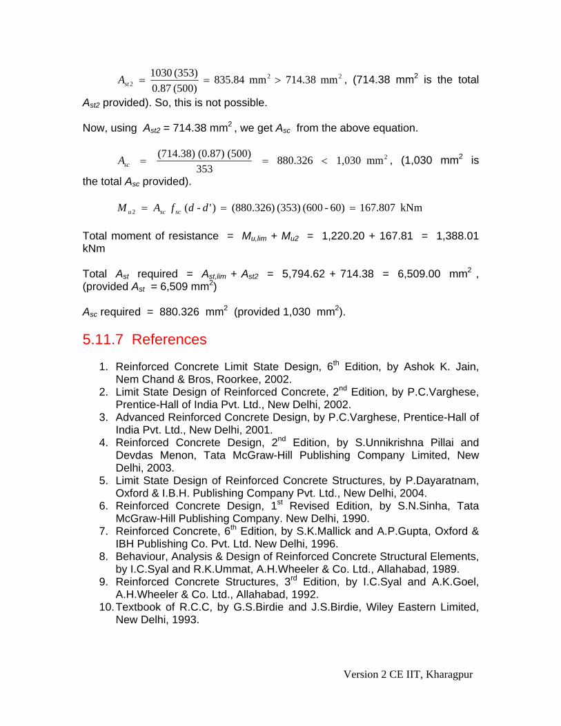
222 mm 714.38 mm 835.84
)500( 87.0(353) 1030 >==stA , (714.38 mm2 is the total
Ast2 provided). So, this is not possible. Now, using Ast2 = 714.38 mm2 , we get Asc from the above equation.
2(714.38) (0.87) (500) 880.326 1,030 mm353scA = = < , (1,030 mm2 is
the total Asc provided). kNm 167.807 60) - (600 (353) (880.326) )' - ( 2 === ddfAM scscu Total moment of resistance = Mu,lim + Mu2 = 1,220.20 + 167.81 = 1,388.01 kNm Total Ast required = Ast,lim + Ast2 = 5,794.62 + 714.38 = 6,509.00 mm2 , (provided Ast = 6,509 mm2) Asc required = 880.326 mm2 (provided 1,030 mm2). 5.11.7 References
1. Reinforced Concrete Limit State Design, 6th Edition, by Ashok K. Jain, Nem Chand & Bros, Roorkee, 2002.
2. Limit State Design of Reinforced Concrete, 2nd Edition, by P.C.Varghese, Prentice-Hall of India Pvt. Ltd., New Delhi, 2002.
3. Advanced Reinforced Concrete Design, by P.C.Varghese, Prentice-Hall of India Pvt. Ltd., New Delhi, 2001.
4. Reinforced Concrete Design, 2nd Edition, by S.Unnikrishna Pillai and Devdas Menon, Tata McGraw-Hill Publishing Company Limited, New Delhi, 2003.
5. Limit State Design of Reinforced Concrete Structures, by P.Dayaratnam, Oxford & I.B.H. Publishing Company Pvt. Ltd., New Delhi, 2004.
6. Reinforced Concrete Design, 1st Revised Edition, by S.N.Sinha, Tata McGraw-Hill Publishing Company. New Delhi, 1990.
7. Reinforced Concrete, 6th Edition, by S.K.Mallick and A.P.Gupta, Oxford & IBH Publishing Co. Pvt. Ltd. New Delhi, 1996.
8. Behaviour, Analysis & Design of Reinforced Concrete Structural Elements, by I.C.Syal and R.K.Ummat, A.H.Wheeler & Co. Ltd., Allahabad, 1989.
9. Reinforced Concrete Structures, 3rd Edition, by I.C.Syal and A.K.Goel, A.H.Wheeler & Co. Ltd., Allahabad, 1992.
10. Textbook of R.C.C, by G.S.Birdie and J.S.Birdie, Wiley Eastern Limited, New Delhi, 1993.
Version 2 CE IIT, Kharagpur

11. Design of Concrete Structures, 13th Edition, by Arthur H. Nilson, David Darwin and Charles W. Dolan, Tata McGraw-Hill Publishing Company Limited, New Delhi, 2004.
12. Concrete Technology, by A.M.Neville and J.J.Brooks, ELBS with Longman, 1994.
13. Properties of Concrete, 4th Edition, 1st Indian reprint, by A.M.Neville, Longman, 2000.
14. Reinforced Concrete Designer’s Handbook, 10th Edition, by C.E.Reynolds and J.C.Steedman, E & FN SPON, London, 1997.
15. Indian Standard Plain and Reinforced Concrete – Code of Practice (4th Revision), IS 456: 2000, BIS, New Delhi.
16. Design Aids for Reinforced Concrete to IS: 456 – 1978, BIS, New Delhi. 5.11.8 Test 11 with Solutions Maximum Marks = 50, Maximum Time = 30 minutes Answer all questions. TQ.1: Determine Mu,lim of the flanged beam of Ex. 2 (Fig. 5.11.3) with the help of SP-16 using (a) M 20 and Fe 250, (b) M 20 and Fe 500 and (c) compare the results with the Mu,lim of Ex. 2 from Table 5.2 when grades of concrete and steel are M 20 and Fe 415, respectively. Other data are: bf = 1000 mm, Df = 100 mm, bw = 300 mm, cover = 50 mm and d = 450 mm.
(10 X 3 = 30 marks) A.TQ.1: From the results of Ex. 2 of sec. 5.11.5 (Table 5.2), we have: Parameters: (i) bf /bw = 1000/300 = 3.33 (ii) Df /d = 100/450 = 0.222 For part (a): When Fe 250 is used, the corresponding table is Table 57 of SP-16. The computations are presented in Table 5.3 below: Table 5.3 (Mu,lim /bw d2 fck) in N/mm2 Of TQ.1 (PART a for M 20 and Fe 250)
(Mu,lim /bw d2 fck) in N/mm2
bf /bwDf /d 3 4 3.33
0.22 0.324 0.411 0.23 0.330 0.421
0.222 0.3252* 0.413* 0.354174* • by linear interpolation Mu,lim /bw d2 fck = 0.354174 = 0.354 (say)
Version 2 CE IIT, Kharagpur
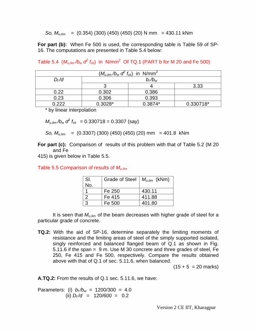
So, Mu,lim = (0.354) (300) (450) (450) (20) N mm = 430.11 kNm For part (b): When Fe 500 is used, the corresponding table is Table 59 of SP-16. The computations are presented in Table 5.4 below: Table 5.4 (Mu,lim /bw d2 fck) in N/mm2 Of TQ.1 (PART b for M 20 and Fe 500)
(Mu,lim /bw d2 fck) in N/mm2
bf /bwDf /d 3 4 3.33
0.22 0.302 0.386 0.23 0.306 0.393
0.222 0.3028* 0.3874* 0.330718* * by linear interpolation Mu,lim /bw d2 fck = 0.330718 = 0.3307 (say) So, Mu,lim = (0.3307) (300) (450) (450) (20) mm = 401.8 kNm
For part (c): Comparison of results of this problem with that of Table 5.2 (M 20
and Fe 415) is given below in Table 5.5. Table 5.5 Comparison of results of Mu,lim
Sl. No.
Grade of Steel
Mu,lim (kNm)
1 Fe 250 430.11 2 Fe 415 411.88 3 Fe 500 401.80
It is seen that Mu,lim of the beam decreases with higher grade of steel for a particular grade of concrete. TQ.2: With the aid of SP-16, determine separately the limiting moments of
resistance and the limiting areas of steel of the simply supported isolated, singly reinforced and balanced flanged beam of Q.1 as shown in Fig. 5.11.6 if the span = 9 m. Use M 30 concrete and three grades of steel, Fe 250, Fe 415 and Fe 500, respectively. Compare the results obtained above with that of Q.1 of sec. 5.11.6, when balanced.
(15 + 5 = 20 marks) A.TQ.2: From the results of Q.1 sec. 5.11.6, we have: Parameters: (i) bf /bw = 1200/300 = 4.0 (ii) Df /d = 120/600 = 0.2
Version 2 CE IIT, Kharagpur

For Fe 250, Fe 415 and Fe 500, corresponding tables are Table 57, 58 and 59, respectively of SP-16. The computations are done accordingly. After computing the limiting moments of resistance, the limiting areas of steel are determined as explained below. Finally, the results are presented in Table 5.6 below:
mm
0.87 {1 - 0.42 (
u ,list ,li
y u,max
MA
f d x / d=
)}
Table 5.6 Values of Mu,lim in N/mm2 Of TQ.2 Grade of Fe / Q.1 of sec. 5.11.6
(Mu,lim/bw d2 fck) (N/mm2 )
Mu,lim (kNm) Ast,lim (mm2)
Fe 250 0.39 1, 263.60 12,455.32 Fe 415 0.379 1, 227.96 7,099.78 Fe 500 0.372 1, 205.28 5,723.76 Q.1 of sec. 5.11.6 (Fe 415)
1, 220.20 5,794.62
The maximum area of steel allowed is .04 b D = (.04) (300) (660) = 7,920 mm2 . Hence, Fe 250 is not possible in this case. 5.11.9 Summary of this Lesson This lesson mentions about the two types of numerical problems (i) analysis and (ii) design types. In addition to explaining the steps involved in solving the analysis type of numerical problems, several examples of analysis type of problems are illustrated explaining all steps of the solutions both by direct computation method and employing SP-16. Solutions of practice and test problems will give readers the confidence in applying the theory explained in Lesson 10 in solving the numerical problems.
Version 2 CE IIT, Kharagpur