Module 4 - Theresa Christina 568825
20
MODULE FOUR Theresa Christina, 568825 Semester 1/2012 Group 8
-
Upload
theresa-christina -
Category
Documents
-
view
213 -
download
0
description
Virtual Environment
Transcript of Module 4 - Theresa Christina 568825

MODULE FOUR Theresa Christina, 568825
Semester 1/2012 Group 8

ideation natural process I began my research by looking into various natural processes including growth of fungi and the pattern formation and venation on a butterfly’s wings, but the process that can be broadly explored and analyzed was the movement of a butterfly’s wings during flight. By observing a slow motion video capture of a butterfly flying (Fig. 1), I realized that when flying, the wings of a butterfly move in a wave-like motion. Hence, I decided to investigate this process further and through the creation of butterfly wing bionics for the thesis project of Silviya Ilieva, I discovered that the wings of a butterfly would alternately and regularly move forward and backward (Stage 1-3, 4-6) to create a flap-like movement which helps in its process of aviation.
Fig 1 – Slow motion video snapshots of a butterfly about to take flight.
Stage 1 Stage 2 Stage 3
Stage 4 Stage 5 Stage 6
This form was derived by trying to combine, sequence, and overlap the process of the back-and-forth movement of the wings during flight.

ideation abstraction At the initial stages of the project, coming up with a form that is not a literal representation of a process was difficult since a process is not something that is tangible and sometimes even not visible. Hence, the initial struggle was to put this intangible, invisible concept to a concept that can be materialized.
However, I gained inspiration from using Infographics as means of deriving a form from an abstract process, since Infographics can be an accurate representation of a process without having the form that closely resembles the process/form itself (e.g. Fig 1). They are also graphically interesting and very pleasing to the eye; hence, for each natural process observed, connections between different points of data relating to the natural process are then sketched to derive a formalized, abstracted form which still relate back to the process directly yet not in the literal sense (Fig 2)
Fig 1 : Infographics showing global corporate connections. Infographics proved that connections can be represented visually without having to show the direct physical form of something, in this case, corporations.
Fig 2 : Form derived from overlaping infographics relating to butterfly migration and the movement graph from a butterfly during flight.
Fig 3: Form derived from sketching and connecting a series of timelapse photograph of a butterfly’s wing movement during flight on a vertical timeline.

ideation form elaboration Based on a precedent by AeroVironment, I discovered that the form I came up with using Infographics as an abstraction method can be further elaborated based on my selected natural process, which is butterfly wing movement (during flight). AeroVironment’s creation of a completely automated butterfly ornithopter (Fig. 1) was guided using 3 basic concepts that butterfly’s wings use to fly: 1. Has wings larger than its body, and each forewing overlap its rear wings. 2. Has a restricted movement
I had much struggle to convey the concept of ‘restrictedness’ in terms of my model’s design. But after seeing NCAD’s poster design promoting their restrictedness-themed collaborative performance (Fig. 2), now I realized that my perception of restriction has been majorly influenced by the idea of something being ‘boxed in’ or ‘caged. Hence, from my initial horizontally-spanning model, which if put into a ‘virtual box’, would produce a long rectangular box, I got the inspiration to compress that virtual box encompassing the model to further develop the model to convey the concept of ‘restriction’. The outcome is, as that virtual box gets compressed into squarer, more compact box, the form would have to follow that frame context and also gets compressed – resulting in a different form (Fig. 3).
Fig 2 Fig 3
Fig 1

ideation context & form Ball, Philip (2011): The Man Who Loved Fluids, In Flow: Nature’s Patterns, Oxford University Press, pp. 1-18
This reading by Phillip Ball is an outstanding demonstration of how context and form influence each other . Leonardo DaVinci’s analytical drawing of water flow shows how form is heavily influenced by context, which in this case can be viewed as an individual’s perspective on a natural process. DaVinci’s form of swirls and eddies– the sketch- is derived from what he thinks the invisible running water movement would be like when it reaches still water. Relating to this reading, it was apparent that all the design-related decisions relating to the natural concept is also heavily reliant on the individual perspective context , as it is the main factor influencing the context of use and resources; The individual is the one gathering all the reachable and obtainable data and resources to support his/her view on a certain matter/process.
This evokes a challenging question that can justify every design decisions taken by a designer – is there any design process and design outcome that can be completely objective rather than subjective to one’s personal views at all?
Timelapse of the movement of bionic butterfly wings by Silviya Ilieva.
Model derived from sequencing the timelapse on a ‘vertical timeline’
Concept of restriction supported by the notion of being boxed in
1. 2. 3. 4.
Derived form – end result from how the form (3) is influenced by the research and data I gathered to support the design context of movement and restriction; The context thus influence the form and is able to be incorporated within the form.
Design Process
Q: HOW DO FORM AND CONTEXT (OF USE AND RESOURCES) INFLUENCE EACH OTHER?

ideation relation to the body
Searching through interesting fashion designs which I could use to enhance the theme of “restrictedness” through the relationship of the lantern with the body , I stumbled onto this piece of work, named ‘Addiction’ featured in a fashion blog called ACQUIRED:KNOWLEDGE. This piece of work is entirely made of couscous, jelly and gold leaf, so in my opinion it perhaps symbolize gluttony, an addiction for food. In many ways, addiction can be related back to “restriction”, because addiction usually limits someone’s potential to be healthy, socially active, and productive at work. Therefore something like this is pretty much spot-on on how I want my lantern to be worn: around the neck, choking and restricting.

design digitization
Fig 1 : Model
Fig 2 : Stretching the model horizontally to simplify section cuts. Fig 3 : Section Cuts
Fig 4 : The digital traced slices arranged linearly
Fig 5 : Awkward, problematic surface outcome.
First trial of the contouring process Because of the geometry of my model, I thought that the appropriate contouring method would be the tracing sectional slices method, which involved slicing the models and tracing it digitally with rhino and arranging it into the correct position. I also ‘opened up’ my model into the original horizontal form so that tracing the contour lines would be easier. However, there were a lot of problems I encountered while using this method to digitize my model because my model is long and thin. It was hard to skewer it so there is no reference point I can follow to arrange the slices in. Hence, the result was quite disastrous since the alignment s are not exact and I reckoned that I should use a different contouring method for my form.

Second trial of the contouring process Since the tracing sectional method did not turn out so well, I tried another contouring method, called tracing profile curves. It involves tracing the profile of the geometry, and then combining it using the Crv2View command. I think this method’s accuracy of forming digital model of my form was not reliable enough, because I only traced the front and top view profile of my model. Also, since the model was again stretched out horizontally, I still needed to use the bend and twist command to alter my model into its curved shape. However, I was having a lot of trouble curving it into the shape I want, since bending and twisting the model often distort the shape and reduce its thickness, greatly reducing its resemblance to the physical clay model. Hence, this technique of digitization does not work well either with my model.
design digitization
Fig 1 : Photograph of model with scale marker for the purpose of digitalization
Fig 2 : Combined traced profile curves
Fig 3: Original Surface Fig 4: Rebuilt Surface Fig 5: Bent surface with “Bend” and “Twist”
Fig 6: Distortion caused by using “PointsOn”

design digitization
Final attempt at digitalizing Going back to the tracing sectional slices method, I learnt that to translate my physical clay model successfully onto Rhinoceros I would not need to stretch out my model horizontally. Instead, I could just try to be more organized (i.e making sure I have sufficient ortographic photographs of my model and making sure I placed the slices in the right order and direction) and just rotate and locate it along the ortographic photographs which have been imported to Rhino using “PictureFrame” instead. Finally, I have a decent digitalized model that can be further developed and panel on.

design form manipulation
Fig 1: Original surface
2x Smooth: factor 0.2
3x Smooth: factor 0.2
4x Smooth: factor 0.2
5x Smooth: factor 0.2
1x Smooth: factor 0.5
2x Smooth: factor 0.5
Rebuilt.
1x Smooth: factor 0.2
The surface outcome from the contouring process needed to be further manipulated, the surface was lumpy and some edges has sharp folds which could create trouble during paneling. Hence, using the command “Smooth” and “Rebuild”, I experimented with various smooth factors and rebuild command to see whether I can further enhance the model so that it would turn out like the physical clay model I created.
Q: How do different media support different kinds of design inquiries and refinement? From this process, I learnt that both the physical media and the digital media has their own limitations in supporting design enquiries and refinement – the physical model is easier to manipulate for partial modifications, but is limited to one’s knowledge and capabilities in creating something hand-made while the digital media is able to facilitate design changes and alterations quickly and effectively and let the user explore all the available design alteration features to modify their model however they wish unconstrained to their own ability in creating something physically but the accuracy would often result in difficulty when altering the model since it will not be able to tolerate any irregularities and would often result in distortions.

design paneling Davide del Giudice With precedent from Davide del Giudice, a professional Rhino modeller from the AAST (Advanced Architecture Settimo Tokyo), I realized that parametric modelling can be used to integrate all aesthetic components together with data in one model. In the case of the Spaceframe (Fig 2 & 3), the parametric models were intended to integrate the architectural components and data into these Spaceframes. Inspired by the concept of linking data with aesthetical qualities within my form, I tried to incorporate the process of butterfly wing movement into the paneling design as well. Since the work of del Giudice represents space using parametric holes, the continuous alternate opening and closing of butterfly movement can also be represented using these holes. Hence, holes are made on every alternate faces to represent this continuous process. Moreover, the extruded faces border which del Giudice also used in one of his Spaceframes design were also applied to my model’s paneling meant to amplify the concept of restriction within the form since it separates one face from another; subsequently it will also function as a ‘restriction’ for the lights.
Fig 1. Fig 2.

fabrication reflection Q: How do different kinds of fabrication technologies make possible as well as constrain what can be constructed?
Module 2 Lectures by Paul Loh and Gerard Pinto gave me an insight of what the work in Module 3 would involve. From the lecture by Gerard Pinto, I learnt that semi-automated fabrication method such as cutting wood using the dimensions measured by digital tools can be extremely useful and helpful as it can measure curves and measurements that the human hand and physical tools will not be able to calculate/measure and in this case, produce needed dimensions of wood cuts and pieces to construct a final product (Fig 4). Without the help of digital modeling tools, such assembly (Fig 5) would be extremely difficult to achieve, nearing impossible since human error will not allow such precise production of curvilinear forms. However, from the design process, it is also apparent that although these technologies help speed up and make possible production process, what can be constructed still heavily relies on the human context since these pre-fabricated pieces would still need to be assembled manually using technical fixatives and supports (Fig 6) by hand; also, since the measurements are already fixed and calculated precisely, the construction process would be highly inflexible and would not tolerate much human error since a slight error would set the construction off. Similarly, the construction of the Times Eureka Pavilion made me realized that although digitally-generated structures and products might be precisely calculated and fabricated, the actual constructing process would be highly dependant on the manual construction techniques and materials used. That is to say, sometimes fabrication technologies limit flexibilities in the construction process and material choice, since the fabricated form might only be able to support certain types of materials structurally.
Fig 4
Fig 5
Fig 1 Fig 2
Fig 3
Fig 6

fabrication refinement Fig 1 Fig 2 Fig 3
Fig 4 Fig 5 Fig 6 Fig 7
To carry on with fabrication, I needed to re-adjust my final form. From module two, I carried a problem to module three. Some of the fins I created as part of my panel designs overlap/intersect each other, making them impossible to be fabricated. So begins my struggle to fix this problem.
There were several steps I took to ensure that the paneling lie smoothly on top of my surface. The first obvious step I took was to use the “Rebuild” command on the surface, but it left me with sharp turns and edges around the surface’s corners, hence, I still needed to resolve this issue to make sure that the paneling do not overlap each other around these edges. Subsequently, I tried using “PointsOn” to adjust the thickness of the model, making sure to retain the design integrity by still maintaining the original qualities and appearance I wanted from my form. After finding that the paneling still overlap each other in some parts, I tried to reduce the density of the panels in those areas by using Curve Attractors. Thankfully, it finally worked and I got my panels to run smoothly along my model, while still having the original appearance I wanted in the first place.

fabrication materialization
In order to manifest the digital model into a physical, tangible form, I needed to unroll the paneling pieces one by one. Moreover, since the panels needed to be unrolled one by one and the unrolling process itself was quite tedious, I decided that the quickest and most effective way of printing these pieces would be through the FabLab, since the card cutter would produce already-cut and etched pieces, saving a huge amount of time. Considering the wearability of the lantern, I also needed to make sure that my final product will come out the right size, big enough to be worn but not too big that it won’t be able to sit on top of my shoulders. Hence, I again used the PictureFrame method used to produce the model’s contours in Module 2 ensuring that it will fit (Fig 1). The scaling and the subsequent unrolling process (Fig 2,3 &4) also made me realize that fabrication technologies such as Rhino depend a lot on the Planarity of surfaces, hence surfaces that are irregular or non-planar will not be able to be fabricated since Rhino will have difficulty unrolling these surfaces and the users would not be able to fold irregular, non-planar surfaces . In other words, fabricating something that are non-planar or aren’t able to be constructed by human hand using a single surface of paper would need more recent fabricating technology such as 3D Printing.
Fig 1 Fig 2 Fig 3 Fig 4

fabrication precedents
The triangular bookshelf (Fig 1 & 2) and the TetraBox lamp (Fig 3 & 4) shows similar fabrication techniques that I can utilize for the construction process of my model. The triangular bookshelf is made in Los Angeles, utilizing a technology called 3D CNC. The design is similar and relevant to my fabrication process because instead of being a regular, rigid bookshelf with a fixed shape, its size grows with the surrounding environment and available space. Since it was produced by 3D technology, much like the project that we are doing now, it is interesting how seemingly precise each faces fit unto each other’s folds , indicating that it was designed and fabricated properly. On the other hand, the TetraBox lamp done by Ed Chew shows more of the manual construction process. The triangular components that make up this light is actually made of recycled drink packets which have been folded to triangles combined to form pentagons or hexagons. I find the lighting effect formed by this light extremely attractive and interesting, because it’s simple yet elegant. It also does not use extravagant materials, just recycled drink packets; hence, this project was very inspirational due to the striking similarity between this lamp design and my lantern design in terms of using triangles as channels to let lights out and the construction process which utilizes triangles which have sides complements the others’. Both of these precedents show the intended outcome of my lantern.
Fig 1
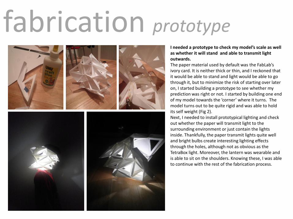
fabrication prototype I needed a prototype to check my model’s scale as well as whether it will stand and able to transmit light outwards. The paper material used by default was the FabLab’s ivory card. It is neither thick or thin, and I reckoned that it would be able to stand and light would be able to go through it, but to minimize the risk of starting over later on, I started building a prototype to see whether my prediction was right or not. I started by building one end of my model towards the ‘corner’ where it turns. The model turns out to be quite rigid and was able to hold its self weight (Fig 2). Next, I needed to install prototypical lighting and check out whether the paper will transmit light to the surrounding environment or just contain the lights inside. Thankfully, the paper transmit lights quite well and bright bulbs create interesting lighting effects through the holes, although not as obvious as the TetraBox light. Moreover, the lantern was wearable and is able to sit on the shoulders. Knowing these, I was able to continue with the rest of the fabrication process.

final model

fabrication final model

reflection Q: How do representations and their material realizations (or insights) may be mutually dependent?
In design processes, representations of inspirations and precedents cannot be avoided since they are the ones giving a form its shape and quality. On the other hand, material realizations show how one perceive things and how they come about representing something abstract and intangible. For instance, I chose to represent the concept of “restriction” in terms of my model’s design by utilizing research and resources, in this case, precedents (National College of Art & Design’s Re;Strict Poster, Fig 1) to support my reasoning that “restriction” should be represented in a way that the model becomes more folded inwards and closing on itself. This way, the representations that were initially subjective to a person’s view become justified through the use of context (use and resources) which is used to support that view. As I stated in Module One, the reading by Phillip Ball, The Man Who Loved Fluids (Fig 2), which mostly talks about how water was described and depicted by different artists and era such as Da Vinci and the Japanese civilization, can be a justification of why these views may sometimes be totally subjective, but with different supporting evidences and explanations, these views can be accepted rationally. Hence, representations affect material realizations in terms that it is the main shaping factor of material realizations and without representations, the material realization might be totally irrelevant or disconnected to the main source of inspiration. Likewise, material realizations can be a measurement of how well a source of inspiration is represented since sometimes people think that a good design must be able to convey the meaning it carries with just one glance. Hence, material realizations is extremely important in a way that the realization must be able to transmit these representations which have been made based on the intended meaning that it was meant to carry; telling the audience the story behind the end product and how the designer has interpreted a source of inspiration in his/her own personal way. The whole project itself has been about incorporating representations (of natural process) into its material realization (the final model). Hence, representations and material realizations are mutually dependent in a way that each of them cannot exist and will not be able to convey meaning on their own, since representation without tangible end products will not say much and material realization without direct representation from the inspiration is just a decorative item without any depth or meaning to it.
Fig 1
Fig 2

reflection Q: What are the learning outcomes of this subject and its relevance to your further studies and future?
I think that the outcome of this subject is highly relevant to my further studies and future. The first obvious positive outcome was that I got to learn to use a 3D modeling software, Rhino, which have been the main digital fabrication media throughout the semester. At the beginning of the semester, I had no clue on how to use any modeling software whatsoever, and I reckon that this new knowledge will play a role in my further studies and future, since I’m intending to major in Architecture, and an architect is a profession that requires a certain amount of knowledge in digital modeling in order to convey ideas and concepts. In addition, since I am going to pursue the path of architecture, this subject has greatly helped me design-wise, as it teaches me that the design process is extremely important, and that I should be able to explain the steps that I take to come up with a certain decisions regarding my design. Prior to taking this subject, I thought that design decisions should be made based on what I THINK would be aesthetically pleasing and attractive. Now, I realized that that type of mindset is extremely subjective to my own personal views, and I did not really have any purpose in doing it and my previous design experience(s) lack depth and meaning. Now that I’ve practiced in applying reasoning and supporting evidence and research in every design decisions I made in this project, I am quite confident that I will be more aware of the decisions I take in the process of subsequent design projects that I will be faced with in the near future. In time, hopefully I will be sensible enough to properly and constantly incorporate meaning in every decisions I make and to link representation to its material realizations and vice versa. Furthermore, the readings, lectures and classs discussions have also enriched my knowledge of the design world, letting me know about what is currently happening in the design world (e.g: 3D Printing becoming more and more prevalent), influential designers of our time and important fabrication techniques and technologies which I previously was not aware of (e.g: Laser Cutter and Card Cutter). I think that all these learning outcomes have broaden my vision and knowledge, and expanded my design standards since I have discovered some things that I didn’t even knew existed prior to enrolling in this subject. Hence, without doubt, this subject has taught me significant lessons which I can bring on to my further studies and future.