Making Surveillance Work Series Module 3 Logistics Management

Manual TABLE OF CONTENTS Module 3. TABLE OF CONTENTS
3-1
MODULE 3. SURVEILLANCE
TABLE OF CONTENTS
3.1 INTRODUCTION . . . . . . . . . . . . . . . . . . . . . . . . . . . . . . . . . . . . . . . . . . . . 3-5MODULE OBJECTIVES . . . . . . . . . . . . . . . . . . . . . . . . . . . . . . . . . . . . . . . . . . . . . 3-5MODULE SCOPE . . . . . . . . . . . . . . . . . . . . . . . . . . . . . . . . . . . . . . . . . . . . . . . . . . . 3-6
3.2 DESIGN PROCESS . . . . . . . . . . . . . . . . . . . . . . . . . . . . . . . . . . . . . . . . . . 3-6PROBLEM IDENTIFICATION . . . . . . . . . . . . . . . . . . . . . . . . . . . . . . . . . . . . . . . . 3-6
Identify and Locate Operational Problems . . . . . . . . . . . . . . . . . . . . . . . . . . . . . . 3-6Determine Functions of Surveillance System . . . . . . . . . . . . . . . . . . . . . . . . . . . . . 3-7
Type of Data . . . . . . . . . . . . . . . . . . . . . . . . . . . . . . . . . . . . . . . . . . . . . . . . . 3-8Traffic Measures. . . . . . . . . . . . . . . . . . . . . . . . . . . . . . . . . . . . . . . . . . . . 3-8Real-Time and Historical Data . . . . . . . . . . . . . . . . . . . . . . . . . . . . . . . . . 3-9
Importance of Data . . . . . . . . . . . . . . . . . . . . . . . . . . . . . . . . . . . . . . . . . . . . 3-9Inventory Existing Surveillance Capabilities . . . . . . . . . . . . . . . . . . . . . . . . . . . . 3-10
IDENTIFICATION OF PARTNERS . . . . . . . . . . . . . . . . . . . . . . . . . . . . . . . . . . . . 3-10Intra-agency . . . . . . . . . . . . . . . . . . . . . . . . . . . . . . . . . . . . . . . . . . . . . . . . . . . . 3-10Interagency (Information Exchange) . . . . . . . . . . . . . . . . . . . . . . . . . . . . . . . . . . 3-11Additional Resources . . . . . . . . . . . . . . . . . . . . . . . . . . . . . . . . . . . . . . . . . . . . . 3-12
ESTABLISH GOALS AND OBJECTIVES . . . . . . . . . . . . . . . . . . . . . . . . . . . . . . . 3-12ESTABLISH PERFORMANCE CRITERIA . . . . . . . . . . . . . . . . . . . . . . . . . . . . . . 3-13DEFINE FUNCTIONAL REQUIREMENTS . . . . . . . . . . . . . . . . . . . . . . . . . . . . . 3-13DEFINE FUNCTIONAL RELATIONSHIPS, DATA REQUIREMENTS, AND
INFORMATION FLOWS . . . . . . . . . . . . . . . . . . . . . . . . . . . . . . . . . . . . . . . . . 3-14IDENTIFY AND SCREEN TECHNOLOGIES . . . . . . . . . . . . . . . . . . . . . . . . . . . . 3-15
Identify Alternative Technologies . . . . . . . . . . . . . . . . . . . . . . . . . . . . . . . . . . . . 3-15Evaluate Alternative Technologies . . . . . . . . . . . . . . . . . . . . . . . . . . . . . . . . . . . 3-16Select Appropriate Technology . . . . . . . . . . . . . . . . . . . . . . . . . . . . . . . . . . . . . 3-16
PLAN DEVELOPMENT . . . . . . . . . . . . . . . . . . . . . . . . . . . . . . . . . . . . . . . . . . . . . 3-17Design Plans . . . . . . . . . . . . . . . . . . . . . . . . . . . . . . . . . . . . . . . . . . . . . . . . . . . . 3-17Specifications . . . . . . . . . . . . . . . . . . . . . . . . . . . . . . . . . . . . . . . . . . . . . . . . . . . 3-17
IDENTIFY FUNDING SOURCES . . . . . . . . . . . . . . . . . . . . . . . . . . . . . . . . . . . . . 3-17IMPLEMENTATION . . . . . . . . . . . . . . . . . . . . . . . . . . . . . . . . . . . . . . . . . . . . . . . 3-19EVALUATION . . . . . . . . . . . . . . . . . . . . . . . . . . . . . . . . . . . . . . . . . . . . . . . . . . . . 3-19
Monitoring Traffic Operations . . . . . . . . . . . . . . . . . . . . . . . . . . . . . . . . . . . . . . 3-20Detecting Incidents . . . . . . . . . . . . . . . . . . . . . . . . . . . . . . . . . . . . . . . . . . . . . . . 3-20Implementing Control Strategies . . . . . . . . . . . . . . . . . . . . . . . . . . . . . . . . . . . . 3-20Monitoring Environmental Conditions . . . . . . . . . . . . . . . . . . . . . . . . . . . . . . . . 3-21
3.3 TECHNIQUES AND TECHNOLOGIES . . . . . . . . . . . . . . . . . . . 3-21SYSTEM COMPONENTS . . . . . . . . . . . . . . . . . . . . . . . . . . . . . . . . . . . . . . . . . . . 3-21
Detection Methods . . . . . . . . . . . . . . . . . . . . . . . . . . . . . . . . . . . . . . . . . . . . . . . 3-22Hardware . . . . . . . . . . . . . . . . . . . . . . . . . . . . . . . . . . . . . . . . . . . . . . . . . . . . . . 3-24
Manual TABLE OF CONTENTS Module 3. TABLE OF CONTENTS
3-2
Software . . . . . . . . . . . . . . . . . . . . . . . . . . . . . . . . . . . . . . . . . . . . . . . . . . . . . . 3-25Incident Detection Algorithms . . . . . . . . . . . . . . . . . . . . . . . . . . . . . . . . . . . 3-25Real-Time Expert Systems . . . . . . . . . . . . . . . . . . . . . . . . . . . . . . . . . . . . . . 3-25
Communications . . . . . . . . . . . . . . . . . . . . . . . . . . . . . . . . . . . . . . . . . . . . . . . . 3-26SURVEILLANCE TECHNOLOGIES . . . . . . . . . . . . . . . . . . . . . . . . . . . . . . . . . . . 3-27EMBEDDED DETECTORS . . . . . . . . . . . . . . . . . . . . . . . . . . . . . . . . . . . . . . . . . . 3-27
Inductive Loop Detector . . . . . . . . . . . . . . . . . . . . . . . . . . . . . . . . . . . . . . . . . . 3-28Characteristics . . . . . . . . . . . . . . . . . . . . . . . . . . . . . . . . . . . . . . . . . . . . . . . 3-28Applications . . . . . . . . . . . . . . . . . . . . . . . . . . . . . . . . . . . . . . . . . . . . . . . . . 3-28Installation Requirements . . . . . . . . . . . . . . . . . . . . . . . . . . . . . . . . . . . . . . 3-32
Magnetometer . . . . . . . . . . . . . . . . . . . . . . . . . . . . . . . . . . . . . . . . . . . . . . . . . . 3-34Characteristics . . . . . . . . . . . . . . . . . . . . . . . . . . . . . . . . . . . . . . . . . . . . . . . 3-34Applications . . . . . . . . . . . . . . . . . . . . . . . . . . . . . . . . . . . . . . . . . . . . . . . . . 3-34Installation Requirements . . . . . . . . . . . . . . . . . . . . . . . . . . . . . . . . . . . . . . 3-34
NON-INTRUSIVE DETECTORS . . . . . . . . . . . . . . . . . . . . . . . . . . . . . . . . . . . . . 3-35Microwave Radar . . . . . . . . . . . . . . . . . . . . . . . . . . . . . . . . . . . . . . . . . . . . . . . . 3-37
Characteristics . . . . . . . . . . . . . . . . . . . . . . . . . . . . . . . . . . . . . . . . . . . . . . . 3-37Continuous Wave. . . . . . . . . . . . . . . . . . . . . . . . . . . . . . . . . . . . . . . . . . 3-37Frequency Modulated Continuous Wave (FMCW) . . . . . . . . . . . . . . . . . 3-37Pulsing Waveform . . . . . . . . . . . . . . . . . . . . . . . . . . . . . . . . . . . . . . . . . 3-37Wide Beam. . . . . . . . . . . . . . . . . . . . . . . . . . . . . . . . . . . . . . . . . . . . . . . 3-38Narrow Beam . . . . . . . . . . . . . . . . . . . . . . . . . . . . . . . . . . . . . . . . . . . . . 3-38Long-Range . . . . . . . . . . . . . . . . . . . . . . . . . . . . . . . . . . . . . . . . . . . . . . 3-38
Applications . . . . . . . . . . . . . . . . . . . . . . . . . . . . . . . . . . . . . . . . . . . . . . . . . 3-39Installation Requirements . . . . . . . . . . . . . . . . . . . . . . . . . . . . . . . . . . . . . . 3-39
Infrared . . . . . . . . . . . . . . . . . . . . . . . . . . . . . . . . . . . . . . . . . . . . . . . . . . . . . . . 3-40Characteristics . . . . . . . . . . . . . . . . . . . . . . . . . . . . . . . . . . . . . . . . . . . . . . . 3-40
Active. . . . . . . . . . . . . . . . . . . . . . . . . . . . . . . . . . . . . . . . . . . . . . . . . . . 3-40Passive . . . . . . . . . . . . . . . . . . . . . . . . . . . . . . . . . . . . . . . . . . . . . . . . . . 3-40
Applications . . . . . . . . . . . . . . . . . . . . . . . . . . . . . . . . . . . . . . . . . . . . . . . . . 3-40Active . . . . . . . . . . . . . . . . . . . . . . . . . . . . . . . . . . . . . . . . . . . . . . . . . . 3-40Passive . . . . . . . . . . . . . . . . . . . . . . . . . . . . . . . . . . . . . . . . . . . . . . . . . . 3-42
Installation Requirements . . . . . . . . . . . . . . . . . . . . . . . . . . . . . . . . . . . . . . 3-42Ultrasonic . . . . . . . . . . . . . . . . . . . . . . . . . . . . . . . . . . . . . . . . . . . . . . . . . . . . . 3-44
Characteristics . . . . . . . . . . . . . . . . . . . . . . . . . . . . . . . . . . . . . . . . . . . . . . . 3-44Applications . . . . . . . . . . . . . . . . . . . . . . . . . . . . . . . . . . . . . . . . . . . . . . . . . 3-44Installation Requirements . . . . . . . . . . . . . . . . . . . . . . . . . . . . . . . . . . . . . . 3-45
Acoustic . . . . . . . . . . . . . . . . . . . . . . . . . . . . . . . . . . . . . . . . . . . . . . . . . . . . . . 3-45Characteristics . . . . . . . . . . . . . . . . . . . . . . . . . . . . . . . . . . . . . . . . . . . . . . . 3-45Applications . . . . . . . . . . . . . . . . . . . . . . . . . . . . . . . . . . . . . . . . . . . . . . . . . 3-45Installation Requirements . . . . . . . . . . . . . . . . . . . . . . . . . . . . . . . . . . . . . . 3-45
Video Image Processing . . . . . . . . . . . . . . . . . . . . . . . . . . . . . . . . . . . . . . . . . . . 3-47Characteristics . . . . . . . . . . . . . . . . . . . . . . . . . . . . . . . . . . . . . . . . . . . . . . . 3-47
Classes of VIP Systems . . . . . . . . . . . . . . . . . . . . . . . . . . . . . . . . . . . . . 3-47VIP Detector Performance . . . . . . . . . . . . . . . . . . . . . . . . . . . . . . . . . . . 3-48Advantages of VIP Systems . . . . . . . . . . . . . . . . . . . . . . . . . . . . . . . . . . 3-49CCTV Applications . . . . . . . . . . . . . . . . . . . . . . . . . . . . . . . . . . . . . . . . 3-50
Manual TABLE OF CONTENTS Module 3. TABLE OF CONTENTS
3-3
Applications . . . . . . . . . . . . . . . . . . . . . . . . . . . . . . . . . . . . . . . . . . . . . . . . . 3-50Installation Requirements . . . . . . . . . . . . . . . . . . . . . . . . . . . . . . . . . . . . . . . 3-51
COMPARISON OF EMBEDDED AND NON-INTRUSIVE DETECTORS . . . . . . 3-51VEHICLE PROBES . . . . . . . . . . . . . . . . . . . . . . . . . . . . . . . . . . . . . . . . . . . . . . . . 3-51
Types of Vehicle Probes . . . . . . . . . . . . . . . . . . . . . . . . . . . . . . . . . . . . . . . . . . . 3-53Automatic Vehicle Identification (AVI) . . . . . . . . . . . . . . . . . . . . . . . . . . . . . 3-53
Active . . . . . . . . . . . . . . . . . . . . . . . . . . . . . . . . . . . . . . . . . . . . . . . . . . . 3-53Passive . . . . . . . . . . . . . . . . . . . . . . . . . . . . . . . . . . . . . . . . . . . . . . . . . . 3-54Semi-Active . . . . . . . . . . . . . . . . . . . . . . . . . . . . . . . . . . . . . . . . . . . . . . 3-54Type I . . . . . . . . . . . . . . . . . . . . . . . . . . . . . . . . . . . . . . . . . . . . . . . . . . . 3-54Type II . . . . . . . . . . . . . . . . . . . . . . . . . . . . . . . . . . . . . . . . . . . . . . . . . . 3-54Type III . . . . . . . . . . . . . . . . . . . . . . . . . . . . . . . . . . . . . . . . . . . . . . . . . 3-54
Automatic Vehicle Location (AVL) . . . . . . . . . . . . . . . . . . . . . . . . . . . . . . . . 3-54Dead-Reckoning and Map-Matching . . . . . . . . . . . . . . . . . . . . . . . . . . . . 3-55Signpost . . . . . . . . . . . . . . . . . . . . . . . . . . . . . . . . . . . . . . . . . . . . . . . . . 3-55Ground-Based Radio-Navigation . . . . . . . . . . . . . . . . . . . . . . . . . . . . . . 3-55LORAN-C . . . . . . . . . . . . . . . . . . . . . . . . . . . . . . . . . . . . . . . . . . . . . . . 3-56Global Positioning System . . . . . . . . . . . . . . . . . . . . . . . . . . . . . . . . . . . 3-56Differential GPS . . . . . . . . . . . . . . . . . . . . . . . . . . . . . . . . . . . . . . . . . . . 3-56
Cellular Telephones . . . . . . . . . . . . . . . . . . . . . . . . . . . . . . . . . . . . . . . . . . . 3-56MOBILE REPORTS . . . . . . . . . . . . . . . . . . . . . . . . . . . . . . . . . . . . . . . . . . . . . . . . 3-57
Cellular Telephones . . . . . . . . . . . . . . . . . . . . . . . . . . . . . . . . . . . . . . . . . . . . . . 3-57Freeway Service Patrols . . . . . . . . . . . . . . . . . . . . . . . . . . . . . . . . . . . . . . . . . . . 3-58Call Boxes/Emergency Telephones . . . . . . . . . . . . . . . . . . . . . . . . . . . . . . . . . . . 3-58
CLOSED-CIRCUIT TELEVISION (CCTV) . . . . . . . . . . . . . . . . . . . . . . . . . . . . . . 3-58Fixed Location . . . . . . . . . . . . . . . . . . . . . . . . . . . . . . . . . . . . . . . . . . . . . . . . . . 3-59
Full Motion Video . . . . . . . . . . . . . . . . . . . . . . . . . . . . . . . . . . . . . . . . . . . . 3-60Compressed Video . . . . . . . . . . . . . . . . . . . . . . . . . . . . . . . . . . . . . . . . . . . . 3-60
Portable . . . . . . . . . . . . . . . . . . . . . . . . . . . . . . . . . . . . . . . . . . . . . . . . . . . . . . . 3-61SUMMARY OF TRAFFIC SURVEILLANCE APPLICATIONS . . . . . . . . . . . . . . 3-61ENVIRONMENTAL DETECTORS . . . . . . . . . . . . . . . . . . . . . . . . . . . . . . . . . . . . 3-62
Freeways . . . . . . . . . . . . . . . . . . . . . . . . . . . . . . . . . . . . . . . . . . . . . . . . . . . . . . 3-62Tunnels . . . . . . . . . . . . . . . . . . . . . . . . . . . . . . . . . . . . . . . . . . . . . . . . . . . . . . . 3-65
3.4 LESSONS LEARNED . . . . . . . . . . . . . . . . . . . . . . . . . . . . . . . . . . . . . . . 3-65OPERATIONS AND MAINTENANCE . . . . . . . . . . . . . . . . . . . . . . . . . . . . . . . . . 3-65
Operations . . . . . . . . . . . . . . . . . . . . . . . . . . . . . . . . . . . . . . . . . . . . . . . . . . . . . 3-65Maintenance . . . . . . . . . . . . . . . . . . . . . . . . . . . . . . . . . . . . . . . . . . . . . . . . . . . . 3-66Operations and Maintenance Costs . . . . . . . . . . . . . . . . . . . . . . . . . . . . . . . . . . . 3-66
PRIVACY CONCERNS . . . . . . . . . . . . . . . . . . . . . . . . . . . . . . . . . . . . . . . . . . . . . 3-67SPACING AND PLACEMENT ISSUES . . . . . . . . . . . . . . . . . . . . . . . . . . . . . . . . 3-70
Mainline Traffic Detectors . . . . . . . . . . . . . . . . . . . . . . . . . . . . . . . . . . . . . . . . . 3-70Spacing . . . . . . . . . . . . . . . . . . . . . . . . . . . . . . . . . . . . . . . . . . . . . . . . . . . . 3-70Placement . . . . . . . . . . . . . . . . . . . . . . . . . . . . . . . . . . . . . . . . . . . . . . . . . . 3-70Non-Intrusive Detectors . . . . . . . . . . . . . . . . . . . . . . . . . . . . . . . . . . . . . . . . 3-71
CCTV Cameras . . . . . . . . . . . . . . . . . . . . . . . . . . . . . . . . . . . . . . . . . . . . . . . . . 3-71
Manual TABLE OF CONTENTS Module 3. TABLE OF CONTENTS
3-4
Site Selection Criteria . . . . . . . . . . . . . . . . . . . . . . . . . . . . . . . . . . . . . . . . . 3-71Preliminary Site Selection . . . . . . . . . . . . . . . . . . . . . . . . . . . . . . . . . . . . . . 3-72Final Site Selection . . . . . . . . . . . . . . . . . . . . . . . . . . . . . . . . . . . . . . . . . . . 3-72
3.5 EXAMPLES . . . . . . . . . . . . . . . . . . . . . . . . . . . . . . . . . . . . . . . . . . . . . . . . . 3-73MIAMI AUTOMATIC VEHICLE LOCATION (AVL) . . . . . . . . . . . . . . . . . . . . . 3-73TRANSCOM ELECTRONIC TOLL AND TRAFFIC
MANAGEMENT (ETTM) . . . . . . . . . . . . . . . . . . . . . . . . . . . . . . . . . . . . . . . . 3-74HOUSTON AUTOMATIC VEHICLE IDENTIFICATION (AVI) . . . . . . . . . . . . . 3-75CONNECTICUT MICROWAVE RADAR . . . . . . . . . . . . . . . . . . . . . . . . . . . . . . . 3-75
3.6 REFERENCES . . . . . . . . . . . . . . . . . . . . . . . . . . . . . . . . . . . . . . . . . . . . . . 3-77
Manual TABLE OF CONTENTS Module 3. TABLE OF CONTENTS
3-5
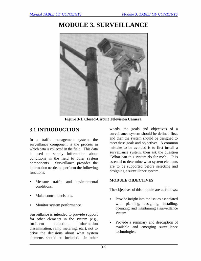
Figure 3-1. Closed-Circuit Television Camera.
MODULE 3. SURVEILLANCE
3.1 INTRODUCTION
In a traffic management system, thesurveillance component is the process inwhich data is collected in the field. This datais used to supply information aboutconditions in the field to other systemcomponents. Surveillance provides theinformation needed to perform the followingfunctions:
C Measure traffic and environmentalconditions.
C Make control decisions.
C Monitor system performance.
Surveillance is intended to provide supportfor other elements in the system (e.g.,incident detection, informationdissemination, ramp metering, etc.), not todrive the decisions about what systemelements should be included. In other
words, the goals and objectives of asurveillance system should be defined first,and then the system should be designed tomeet these goals and objectives. A commonmistake to be avoided is to first install asurveillance system, then ask the question“What can this system do for me?”. It isessential to determine what system elementsare to be supported before selecting anddesigning a surveillance system.
MODULE OBJECTIVES
The objectives of this module are as follows:
C Provide insight into the issues associatedwith planning, designing, installing,operating, and maintaining a surveillancesystem.
C Provide a summary and description ofavailable and emerging surveillancetechnologies.
Manual TABLE OF CONTENTS Module 3. TABLE OF CONTENTS
3-6
MODULE SCOPE
The intent of this module is to helpengineers/planners in the decision process C Inventorying existing surveillanceinvolved in implementing an appropriate capabilities.surveillance system. Included in this moduleare a description of the decision process, a Table 3-1 describes the objectives forsummary of the components of a surveillance conducting each of the above tasks.system, a discussion of available andemerging surveillance technologies, andexamples of existing traffic managementcenters that are using various surveillancetechnologies. In addition, special issues such This process involves identifying thoseas privacy concerns and spacing freeways that would greatly benefit from therequirements for sensors are addressed. use of surveillance and traffic management.
3.2 DESIGN PROCESS
This section describes the process forplanning, designing, and installing asurveillance system. Issues associated withoperations and maintenance are alsoaddressed. The focus of this section is onthe decision process involved inimplementing a surveillance system using asystems engineering approach. Instead offocusing on technological solutions toperceived problems, the system engineeringapproach described in this section involvesidentifying user needs and systemrequirements first, and then designing asystem to meet these needs andrequirements.
PROBLEM IDENTIFICATION
The first step in the decision process is toidentify the problems to be addressed by thesystem. Issues that should be addressed inthe problem identification stage include thefollowing:
C Identifying and locating operationaldeficiencies.
C Determining functions to be performedby surveillance system.
Identify and Locate OperationalProblems
Areas benefiting the most would be thosewith significant amounts of congestion.There are two types of congestion:
C Recurring. Typically predictable andoccurs at locations where demandexceeds capacity or at geometricbottlenecks (e.g., lane drops, high-volume entrance ramps, etc.).
C Nonrecurring. Caused by a randomevent (e.g., incident, maintenanceactivity, special event, etc.) and has theeffect of reducing the capacity on aspecific section of freeway.
Whether the congestion is recurring or non-recurring, the effects on traffic operationsinclude:(1)
C Increased delay.
C Slower and inconsistent travel speeds.
C Increased accident potential.
C Other undesirable characteristics.
Manual TABLE OF CONTENTS Module 3. TABLE OF CONTENTS
3-7
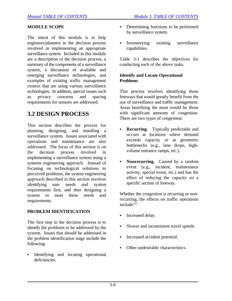
Table 3-1. Tasks Involved in Problem Identification.
Task Objective
Identify Operational C Identify freeway sections to receive surveillance systemProblems
Determine Functions of C Evaluate freeway system to determine surveillance needsSurveillance System C Determine type of data needed
C Determine importance of dataC Develop criteria for selecting detection technology
Inventory Existing C Determine if existing system needs to be replaced/expanded basedSurveillance on cost and needsCapabilities C Estimate how long the existing system will be able to meet the
needsC Identify advantages and disadvantages of existing system to aid in
the process of selecting new equipment
Other freeways that might be considered for C Detect incidents that have an impact onsurveillance include the following: traffic operations.
C Freeways in areas in which significant C Monitor incidence clearance.increases in traffic demand are expected.
C Freeways in areas with significant implementation of control strategies (e.g.,amounts of maintenance or construction lane control, ramp metering, etc.).activities.
C Freeways in areas with high frequencies of conditions (e.g., flood, ice, winds, fog,traffic incidents. etc.).
These areas can expect an increase in Table 3-2 lists several scenarios in whichcongestion, and surveillance in combination surveillance is used and typical methods thatwith traffic management may be used as an meet the surveillance needs.alternative to the very expensive solution ofbuilding additional lanes. The type of surveillance system needed
Determine Functions of SurveillanceSystem
A surveillance system can serve several collected through surveillance systems andpurposes, including the following: factors that should be considered when
C Monitor traffic operations and support the
C Monitor environmental and pavement
depends not only on the purpose(s) that itwill serve, but also the type and importanceof data to be collected. The followingsections discuss the types of data typically
determining the importance of the data.
Manual TABLE OF CONTENTS Module 3. TABLE OF CONTENTS
3-8
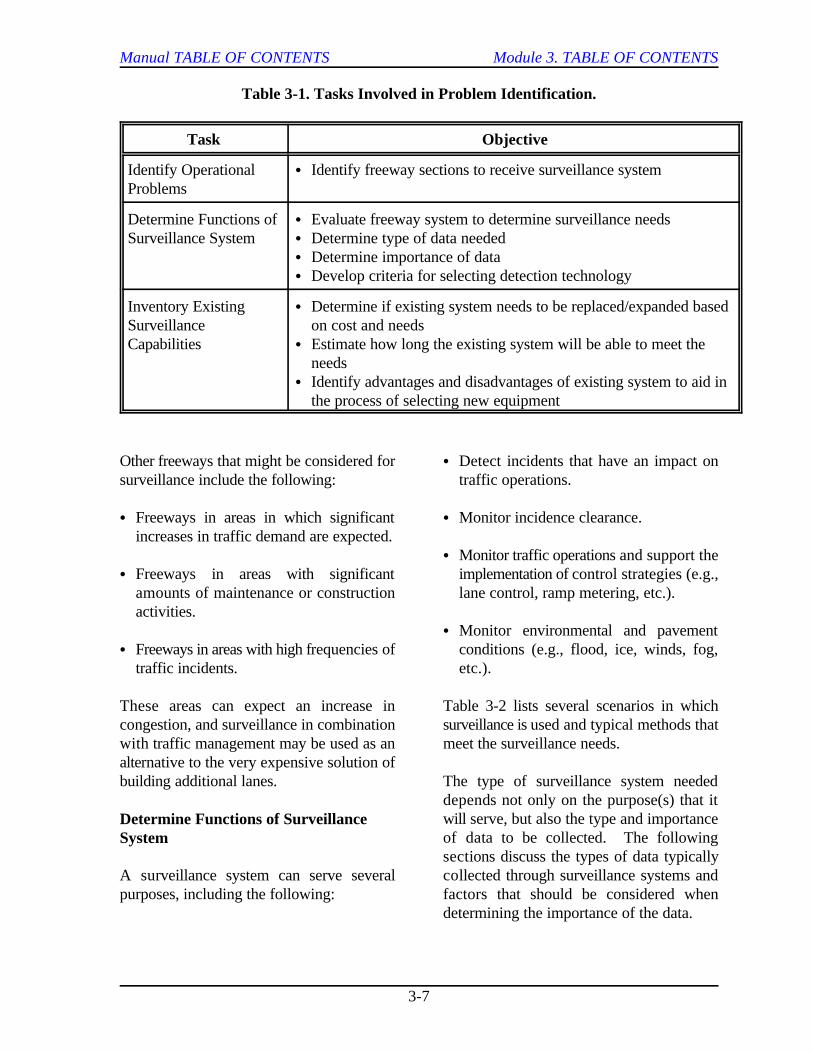
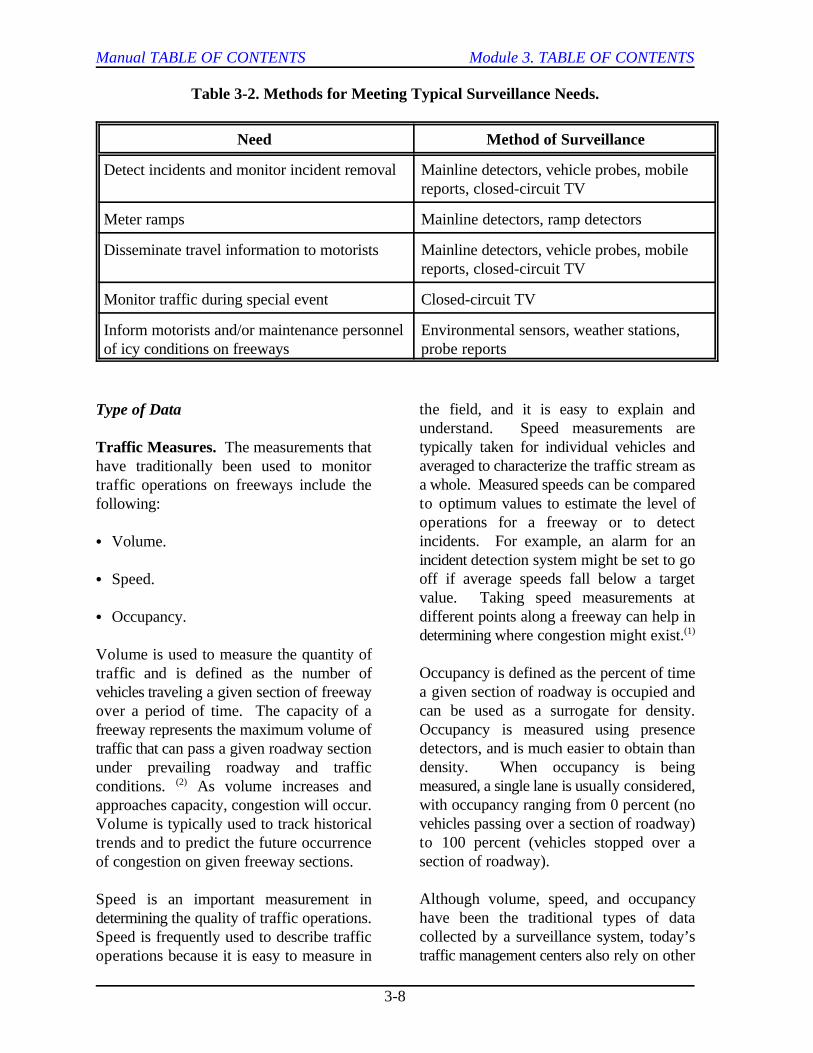
Table 3-2. Methods for Meeting Typical Surveillance Needs.
Need Method of Surveillance
Detect incidents and monitor incident removal Mainline detectors, vehicle probes, mobilereports, closed-circuit TV
Meter ramps Mainline detectors, ramp detectors
Disseminate travel information to motorists Mainline detectors, vehicle probes, mobilereports, closed-circuit TV
Monitor traffic during special event Closed-circuit TV
Inform motorists and/or maintenance personnel Environmental sensors, weather stations,of icy conditions on freeways probe reports
Type of Data
Traffic Measures. The measurements thathave traditionally been used to monitortraffic operations on freeways include thefollowing:
C Volume.
C Speed.
C Occupancy.
Volume is used to measure the quantity oftraffic and is defined as the number ofvehicles traveling a given section of freewayover a period of time. The capacity of afreeway represents the maximum volume oftraffic that can pass a given roadway sectionunder prevailing roadway and trafficconditions. As volume increases and(2)
approaches capacity, congestion will occur.Volume is typically used to track historicaltrends and to predict the future occurrenceof congestion on given freeway sections.
Speed is an important measurement indetermining the quality of traffic operations.Speed is frequently used to describe trafficoperations because it is easy to measure in
the field, and it is easy to explain andunderstand. Speed measurements aretypically taken for individual vehicles andaveraged to characterize the traffic stream asa whole. Measured speeds can be comparedto optimum values to estimate the level ofoperations for a freeway or to detectincidents. For example, an alarm for anincident detection system might be set to gooff if average speeds fall below a targetvalue. Taking speed measurements atdifferent points along a freeway can help indetermining where congestion might exist.(1)
Occupancy is defined as the percent of timea given section of roadway is occupied andcan be used as a surrogate for density.Occupancy is measured using presencedetectors, and is much easier to obtain thandensity. When occupancy is beingmeasured, a single lane is usually considered,with occupancy ranging from 0 percent (novehicles passing over a section of roadway)to 100 percent (vehicles stopped over asection of roadway).
Although volume, speed, and occupancyhave been the traditional types of datacollected by a surveillance system, today’straffic management centers also rely on other
Manual TABLE OF CONTENTS Module 3. TABLE OF CONTENTS
3-9
types of data for traffic management C To perform before/after analyses topurposes. Examples of other data include determine the effects of implementingthe following: certain traffic management techniques.
C Vehicle travel times. C To create simulation models for analyzing
C Bus location.
C Emergency vehicle location. priorities for deployment.
C Queue length.
C Pavement condition. In the decision process involved in selecting
Until recently, most of the data listed above importance of the data to be collected mustwas difficult to measure in the field; be identified to establish the datahowever, due to improvements in detector requirements. The following factors shouldtechnologies, these measurements can now be considered when determining the databe obtained. requirements:
Real-Time and Historical Data. Both real-time and historical data may be used fortraffic management purposes. Real-timedata is needed for the following purposes ina freeway management system:
C Monitoring current traffic operating andenvironmental conditions.
C Detecting incidents.
C Implementing control strategies.
Historical data refers to past trafficconditions on a given section of freeway.Historical data can be used for severalpurposes, including the following:
C To establish a record of past trafficconditions on a certain freeway section.
C To compare real-time data to historicaldata to determine irregular traffic patterns;results of this comparison can be used todetect traffic congestion and incidents.
potential improvements.
C To create planning models for establishing
Importance of Data
an appropriate surveillance system, the
C Speed.
C Accuracy.
C Cost.
The speed of a surveillance system relates tothe frequency in which information aboutfield conditions is relayed to the trafficmanagement center. Speed plays animportant role for some applications. Forexample, in order to minimize the effects ofan incident on freeway operations, it isimportant to minimize the detection time. Inaddition, the speed of data collection isimportant when the data is used toimplement a control strategy to reduce orprevent the formation of congestion.
Other factors must be considered whendetermining the speed of a surveillancesystem. The speed of the data collectiondetermines the amount of data to betransmitted to the traffic control center.Therefore, operator overload should betaken into consideration. In addition, theamount and speed of data collection affects

Manual TABLE OF CONTENTS Module 3. TABLE OF CONTENTS
3-10
the type of communication system required. The capabilities of the existingAs the amount of data to be transmitted communications system should be evaluated,increases, the communication requirements because the various detection technologiesincrease. available have different communications
Data accuracy requirements are also full-motion video requires a widedependent upon the elements that the communication bandwidth (such as thatsurveillance system is to support. For provided by fiber optic cable); however,example, the accuracy of the data is transmitting only data requires considerablyimportant for incident detection systems to less bandwidth than can be met by mostavoid false alarms. Accuracy, however, may communication media.not be as crucial when collecting traffic datafor traveler information systems. Typically, Existing infrastructure on which non-the faster and more accurate a surveillance intrusive detectors and CCTV cameras maysystem is, the more it is going to cost; be mounted should be identified at this stage.therefore, it is important to balance speed, In addition, existing conduit for theaccuracy, and cost when choosing a communication system should also be noted.system.(3)
Inventory Existing SurveillanceCapabilities
The existing surveillance resources should be partners to be involved. Partners should beidentified and evaluated to determine if they considered in the following three areas:are suitable for continued use. Theevaluation should include items such as the C Intra-agency (within agency).following: .(4)
C Detectors.
C Controllers.
C Communication media.
It is important to determine if these interested groups and individuals that will becomponents can meet existing needs and if involved in the surveillance system should bethey can accommodate changes in system identified and included in the decisionrequirements. The existing surveillance making process. The project team shouldsystem should be evaluated to determine if include representatives from the followingthe required speed and accuracy of data areas:collection are attainable. Other factors thatshould be considered are the reliability and C Management.required maintenance of the existing system.It may be more cost effective in the long run C Planning.to replace a system that requires extensivemaintenance with a more reliable, low C Design.maintenance system.
requirements. For example, transmitting
IDENTIFICATION OF PARTNERS
Another important step in implementing asuccessful surveillance system is to identify
C Interagency (between agencies).
C Additional resources.
Intra-agency
During the planning and design stages, all
(4)
Manual TABLE OF CONTENTS Module 3. TABLE OF CONTENTS
3-11
C Operations. take place between the following public
C Maintenance.
Including representatives from each of theseareas will help ensure the success of the C City.system. For example, it is important toinclude persons from management on the C County.team to help gain support for thesurveillance system. Since freeway C Transit.management systems often compete forfunding with other agency expenditures, the C MPO.support from top management is essential ifagency resources are to be allocated to the Sharing information about the occurrence ofoperation and maintenance of the system. incidents between agencies permits jointBy including representatives from operations incident management by two or moreand maintenance, the following issues may agencies. This allows more than onebe addressed: agency to be involved in responding to and
C Support staff required for surveillance place between public transportation agenciessystem. and the following enforcement and
C Number and qualifications of existingsupport staff. C Police.
C Training required to operate and maintain C Fire.specific surveillance systems.
Using this team approach, specific concernsand requirements from each area can be C Wrecker operators.addressed from the beginning. The teamshould then prioritize the requirements to Real-time traffic information may be relayeddetermine which are most important and to the motorists through traveler informationwhich are desirable but not needed. systems such as dynamic message signs,
Interagency (Information Exchange)
During the operation of a traffic providing real-time traffic data to themanagement system, it is important for following sources:public agencies to exchange certaininformation on a continual basis. C Media.Information to be exchanged includesscheduled maintenance activities and special C Cable television companies.events. This coordination between agencieswill ensure that proper measures are taken to C Public kiosks.minimize the effects of the event on overalltraffic operations. Data exchange should C Other traffic advisory services.
transportation agencies:
C State.
(4)
clearing incidents. Data exchange may take
emergency agencies and companies:
C Medical.
highway advisory radio, or in-vehicleinformation systems. In addition, motoristsmay be informed about traffic conditions by
Manual TABLE OF CONTENTS Module 3. TABLE OF CONTENTS
3-12
Another private sector entity that benefits strengths and weaknesses. In addition,from real-time traffic data is commercial researchers produce technological advancesvehicle operators. For example, dispatchers in surveillance systems.can use information about current trafficconditions to re-route commercial vehicles inan effort to minimize delay for thecommercial drivers. This not only benefitsoperators of the commercial vehicles, but it To establish the goals and objectives of aalso benefits other vehicles in areas of heavy system, it is important to identify what thecongestion by directing the commercial system is to accomplish. Goals are used tovehicles away from the congested areas. define the long-range desires for the system.
Additional Resources
During the process of selecting the objectives are defined in terms of whatappropriate equipment to be used in the services and functions the system is tosurveillance system, it is important to provide — not in terms of technology. Theidentify and evaluate all of the alternatives. focus should be on what the system is toBecause of the constant change in available achieve instead of on how it is to achieve it.systems, the following groups should beconsidered as resources during the planning As discussed earlier, the surveillance systemand design of a surveillance system: provides support for other elements of a(4)
C Manufacturers. management, information dissemination,. ramp control, etc.). Therefore, the goals andC Suppliers. objectives of the surveillance system must
C Users. elements that it is supporting. For example,
C Researchers. to reduce the impact of incidents on traffic
C Consultants. might be to detect an incident in less than
C Other interested groups or individuals. clearance time by five minutes. The
Manufacturers continually develop and determining the system’s ability to meetimprove system capabilities and therefore these established objectives.can provide information on the state-of-the-art in surveillance technology. Information Since the goals and objectives of aon the equipment specifications, functional surveillance system relate to those of theand design features, and costs may be element that the surveillance system isobtained from the manufacturers and supporting, the reader is referred to thesuppliers. Users of available systems specific modules within this report thatdevelop unique approaches for some systems address each element. Additional goals andand can provide evaluations for certain objectives of a surveillance system mighttechnologies. Researchers and consultants include those that relate to monitoring thetest the available technologies to determine performance of a certain system. For
(4)
ESTABLISH GOALS ANDOBJECTIVES
Objectives define the level of performancethat is to be expected in the future. At thisstage, it is important to note that system
traffic management system (such as incident
relate to the goals and objectives of the
a goal of an incident management system is
operations. The objectives of the system
two minutes and reduce the incident
surveillance system can be evaluated by
Manual TABLE OF CONTENTS Module 3. TABLE OF CONTENTS
3-13
example, a goal might be to ensure that the quantifiable measures. The measuresproper message is being displayed on a identified will be based on the elements ofdynamic message sign. Objectives would be the traffic management system that theto determine if the sign was operational and surveillance component will support. Into identify the message being displayed. addition, the established performanceOther goals and objectives of a surveillance measures will be based on local concerns andsystem might relate to the effects of policies. Table 3-3 provides some examplesimplementing certain control strategies. of performance measures that may be used
ESTABLISH PERFORMANCECRITERIA DEFINE FUNCTIONAL
There is currently a wide range of trafficdetectors from which to choose, and with The next step in the decision processadvancements in technology, the number of involves defining all of the functions of aalternatives is becoming even greater. It is system that are necessary to achieve theimportant, therefore, to establish established objectives. At this stage, theperformance criteria to aid in the selection of focus should still be on what the system willan optimum system. Establishing be designed to do, not how the system willperformance criteria allows alternative do it. Therefore, the functions should besystems to be compared against these criteria defined independent of the availablein a later task. technology.
The established performance criteria should Again, the surveillance system providesbe related to the ability of the system to meet support to other elements in a trafficthe pre-established goals and objectives. management system. Therefore, theCriteria that may be used to measure the functional requirements of a surveillanceperformance of a surveillance system include system are dependent upon the element thatthe following: it will support. For a surveillance system,
C Reliability of system. the type, frequency, and quantity of data
C Accuracy of data. freeway surveillance have included measures
C Timeliness of data. however, surveillance should not be limited
Each of the above criteria is important in might include travel time, queue length,measuring the performance of a system. For headway, origin/destination, vehicleexample, a system is not effective if it classification, etc. These measures haveprovides accurate data but produces it 30 been difficult to obtain in the past but canminutes after it is needed. now be measured because of improvements
The above criteria should be used toestablish parameters by which to evaluate the In the past, various surveillance conceptssystem. The desired performance of the have been investigated in an attempt to meetsystem together with a selected range of different functional requirements, and havetolerance should be used to develop failed. Some of these concepts failed
to evaluate a surveillance system.
REQUIREMENTS
the functional requirements typically relate to
required. The data typically used for
such as volume, speed, and occupancy;
to these measures only. Additional measures
in technology.
Manual TABLE OF CONTENTS Module 3. TABLE OF CONTENTS
3-14
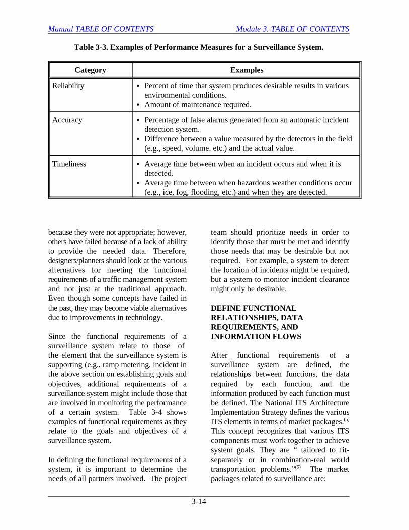
Table 3-3. Examples of Performance Measures for a Surveillance System.
Category Examples
Reliability C Percent of time that system produces desirable results in variousenvironmental conditions.
C Amount of maintenance required.
Accuracy C Percentage of false alarms generated from an automatic incidentdetection system.
C Difference between a value measured by the detectors in the field(e.g., speed, volume, etc.) and the actual value.
Timeliness C Average time between when an incident occurs and when it isdetected.
C Average time between when hazardous weather conditions occur(e.g., ice, fog, flooding, etc.) and when they are detected.
because they were not appropriate; however, team should prioritize needs in order toothers have failed because of a lack of ability identify those that must be met and identifyto provide the needed data. Therefore, those needs that may be desirable but notdesigners/planners should look at the various required. For example, a system to detectalternatives for meeting the functional the location of incidents might be required,requirements of a traffic management system but a system to monitor incident clearanceand not just at the traditional approach. might only be desirable.Even though some concepts have failed inthe past, they may become viable alternativesdue to improvements in technology.
Since the functional requirements of asurveillance system relate to those of the element that the surveillance system is After functional requirements of asupporting (e.g., ramp metering, incident in surveillance system are defined, thethe above section on establishing goals and relationships between functions, the dataobjectives, additional requirements of a required by each function, and thesurveillance system might include those that information produced by each function mustare involved in monitoring the performance be defined. The National ITS Architectureof a certain system. Table 3-4 shows Implementation Strategy defines the variousexamples of functional requirements as they ITS elements in terms of market packages.relate to the goals and objectives of a This concept recognizes that various ITSsurveillance system. components must work together to achieve
In defining the functional requirements of a separately or in combination-real worldsystem, it is important to determine the transportation problems.” The marketneeds of all partners involved. The project packages related to surveillance are:
DEFINE FUNCTIONALRELATIONSHIPS, DATAREQUIREMENTS, ANDINFORMATION FLOWS
(5)
system goals. They are “ tailored to fit-
(5)
Manual TABLE OF CONTENTS Module 3. TABLE OF CONTENTS
3-15
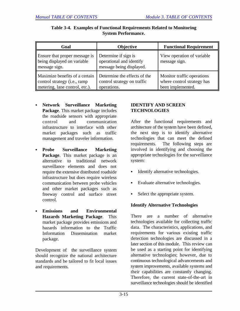
Table 3-4. Examples of Functional Requirements Related to MonitoringSystem Performance.
Goal Objective Functional Requirement
Ensure that proper message is Determine if sign is View operation of variablebeing displayed on variable operational and identify message sign.message sign. message being displayed.
Maximize benefits of a certain Determine the effects of the Monitor traffic operationscontrol strategy (i.e., ramp control strategy on traffic where control strategy hasmetering, lane control, etc.). operations. been implemented.
C Network Surveillance Marketing IDENTIFY AND SCREENPackage. This market package includesthe roadside sensors with appropriatecontrol and communicationinfrastructure to interface with othermarket packages such as trafficmanagement and traveler information.
C Probe Surveillance MarketingPackage. This market package is analternative to traditional networksurveillance elements and does notrequire the extensive distributed roadsideinfrastructure but does require wirelesscommunication between probe vehiclesand other market packages such asfreeway control and surface streetcontrol.
C Emissions and EnvironmentalHazards Marketing Package. Thismarket package provides emissions andhazards information to the TrafficInformation Dissemination marketpackage.
Development of the surveillance systemshould recognize the national architecturestandards and be tailored to fit local issuesand requirements.
TECHNOLOGIES
After the functional requirements andarchitecture of the system have been defined,the next step is to identify alternativetechnologies that can meet the definedrequirements. The following steps areinvolved in identifying and choosing theappropriate technologies for the surveillancesystem:
C Identify alternative technologies.
C Evaluate alternative technologies.
C Select the appropriate system.
Identify Alternative Technologies
There are a number of alternativetechnologies available for collecting trafficdata. The characteristics, applications, andrequirements for various existing trafficdetection technologies are discussed in alater section of this module. This review canbe used as a starting point for identifyingalternative technologies; however, due tocontinuous technological advancements andsystem improvements, available systems andtheir capabilities are constantly changing.Therefore, the current state-of-the-art insurveillance technologies should be identified
Manual TABLE OF CONTENTS Module 3. TABLE OF CONTENTS
3-16
in this stage. To identify available each type of surveillance technologytechnologies, it is important to continually included in the analysis:interface with the following groups andindividuals during the identification C Location of sensors (i.e., embedded orprocess: non-intrusive).(4)
C Manufacturers. C Installation, operation, and maintenance
C Suppliers.
C Users.
C Consultants.
C Researchers.
C Other interested individuals. available.
By keeping in contact with these groups and C Requirements for future expansion.individuals, the analyst can accomplish thefollowing: After the initial screening, the detailed
C Keep up with current trends in steps:technology.
C Identify the advantages and alternative.disadvantages of available systems.
C Obtain information on systemspecifications and costs. C Selecting the system offering the greatest
Evaluate Alternative Technologies
The first step in evaluating alternative evaluated. There are many techniquestechnologies is to identify the selection available to perform an analysis of the costscriteria (see previous section, EstablishPerformance Criteria). The next stepinvolves the following measures:
C Initial screening of all availabletechnologies.
C Detailed evaluation of the remainingalternatives.
During the initial screening process, thefollowing factors should be considered for
requirements.
C Reliability.
C Expected life.
C Life-cycle costs.
C Type of communications medium
evaluation typically includes the following(4)
C Estimating costs and benefits of each
C Performing comparative analyses.
potential.The advantages and disadvantages of thesystem must be quantified or weighted and
and benefits for each alternative. Module11 contains descriptions of procedures forperforming a benefit-cost analysis.
Select Appropriate Technology
Surveillance technologies that are viablealternatives should have benefits thatoutweigh the costs. The argument can bemade that the best system will have thegreatest benefit-cost ratio; however, this is
Manual TABLE OF CONTENTS Module 3. TABLE OF CONTENTS
3-17
not always the case. For example, a simple,low-cost system with fewer benefits mayhave the same benefit-cost ratio as a more Specifications contain detailed informationsophisticated, affordable system with more on the minimum acceptable standards for thebenefits. Therefore, the analysis should surveillance system’s equipment along withinclude allowable expenditures for the procedures on how the equipment should besystem and the net benefits of each installed. Detailed specifications arealternative. important to ensure that the proper(4)
PLAN DEVELOPMENT
After the technologies that will be used inthe system have been selected, the next step C Federal Highway Administration.is to develop a plan for implementation. TheImplementation Plan documents the results C Institute of Transportation Engineers.of the previous steps and identifies how thesystem will be implemented in the field. The C Other State transportation departments.Implementation Plan should also assess thephasing, procurement, staffing, and funding These specifications may be used as theyoptions available for implementing the exist or modified to fit particular needs.system. Module 2 contains a description ofelements that should be included in theImplementation Plan.
One of the tasks at this stage is to develop IDENTIFY FUNDING SOURCESthe design plans and specifications. Thistask involves transforming the needs and As described in Module 2, funding sourcesgoals of the surveillance system into design should be identified during the developmentdocuments and specifications suitable for of the Implementation Plan. Funding forcompetitive bids. The plans include surveillance systems may come from bothdrawings that show the physical layout of the Federal and State levels. On the Federalthe system, and the specifications define the level, funding is available through thequality and type of workmanship and Intermodal Surface Transportationmaterials. Efficiency Act (ISTEA) and continuing with(4)
Design Plans
The design plans provide information for the expenses for traffic management programscontractor and equipment supplier to are eligible for Federal aid. By includingprepare a project bid and for the projects in the Transportation Improvementconstruction manager to aid in controlling Program (a spending plan required by thethe construction. Table 3-5 shows typical Federal government), agencies can receiveinformation that should be provided on the federal funds. Under Title 23 of the Uniteddesign plans. States Code (as amended by the ISTEA of(4)
Specifications
equipment is obtained. Sources forequipment and materials specificationsinclude the following:(4)
Guidelines for specifications for the variouscomponents of a surveillance system areprovided in table 3-6.(4)
the proposed National Economic CrossroadsTransportation Efficiency Act (NEXTEA).Under the ISTEA act, capital and operating
1991) the following funding sources can beused to purchase and operate freewaymanagement surveillance systems:

Manual TABLE OF CONTENTS Module 3. TABLE OF CONTENTS
3-18
Table 3-5. Typical Information in Design Plan. (4)
Item Description
Title Sheet Shows name, location, and scope of project.
Summary of Shows material and equipment quantities.Quantities
General Notes Frequently call special attention to critical requirements to ensure theyare not overlooked; must avoid conflicts with specifications.
Site Schematics Scale drawings of each site showing the roadway geometry, locationof poles, conduit locations, and any other pertinent site information.
Construction Design Shows locations of detectors to be installed and minimumDrawings requirements for construction dimensions.
Traffic Control Plan Indicates handling of traffic during construction.
Details of Barricades Illustrates the construction phase of the project.and Signing
Diagram of Shows details of location.Underground Utilities
Standard Plans Possessed by each agency, generally provide numerous standarddrawings of frequently encountered details already approved for usein situations applicable to the project.
Table 3-6. Guidelines for Specifications. (4)
Specification Guidelines
Detectors Include physical properties, electricalproperties, environmental conditions underwhich the equipment must operate, controls,and methods of operation.
Computer Software Provide functional specifications for controlsoftware, compilers, assemblers, utilities, anddiagnostic programs.
Video Terminals Specify sample operator screens and controls,screen size, refresh rate, and colors.
CCTV Monitoring Specify monitors, cameras, and interfaceprotocols.
Manual TABLE OF CONTENTS Module 3. TABLE OF CONTENTS
3-19
C Surface Transportation Program (STP). process. Additional issues that should be
C National Highway System (NHS). system include the following:
C Congestion Mitigation and Air Quality C Phasing of installation.Program (CMAQ).
STP funds are available on eligible projectswith no time limit. NHS and CMAQ funds During the installation of a surveillancehave definite time limits, and cannot be used system, some disruptions to traffic are to befor maintenance. expected. To minimize delay to traffic,(6)
Although some Federal funds are available peak hours. In addition, the maximumfor operating costs, Title 23 funds are number of lanes that can be simultaneouslygenerally used for system deployment and closed should be specified. When possible,start-up assistance. Typically, funding for phasing of installation for the surveillanceboth operations and maintenance costs are system should be coordinated with otherprovided on the State and local levels freeway construction to minimize the overallthrough maintenance budgets. Funding delay to traffic.operations and maintenance costs forsurveillance systems through the Another area that must be addressed duringmaintenance budgets often causes problems the implementation of a system is thebecause of competition from other development of training programs fortraditional maintenance activities. operators and maintenance personnel.Therefore, it is crucial to identify the funding Training should provide the technical skillneeds and funding sources for operation and necessary to effectively operate and maintainmaintenance activities early in the decision the system. The amount of training requiredprocess. depends upon the qualifications and
Public/private partnership is an approach requirements of the new system. Forthat many agencies are using to increase the example, maintenance personnel that aresource of funding for traffic management familiar with an inductive loop detectionpurposes. For example, many cellular system will require extensive training totelephone companies offer free or reduced maintain a video image processing system.rates to agencies for incident detection Additional information concerning trainingpurposes. This approach allows other requirements is contained in reference 9.partners to get involved in a fair andequitable manner.
IMPLEMENTATION
The implementation process includes the its effectiveness in meeting the objectives.activities involved in installing the The objectives of a surveillance system maycomponents of the surveillance system to include any of the following:meet the established goal and objectives.Module 2 gives a description of issues to beaddressed during the implementation
considered when implementing a surveillance
C Training.
construction should take place during off-
(4)
knowledge of existing personnel and the
EVALUATION
After a surveillance system has beeninstalled, the system should be evaluated for
C Monitoring traffic operations.
Manual TABLE OF CONTENTS Module 3. TABLE OF CONTENTS
3-20
C Detecting incidents. speed, occupancy, etc.) measured upstream
C Supporting implementation of controlstrategies. After an incident detection system has been
C Monitoring environmental conditions. evaluated to calibrate the incident detection
Monitoring Traffic Operations
The goals of monitoring traffic operationsinclude: C CCTV.
C Providing measures of traffic operations C Mobile reports (cellular call-ins, call(e.g., speed, flow, density, etc.). boxes, service patrols, etc.).
C Identifying locations of congestion. C Emergency channels.
C Indicating the severity of congestion. The algorithm is calibrated by adjusting the
Records should be kept to track system effectiveness typically used for calibration isoperations and note any problems. An the false alarm rate. Threshold values areoverall evaluation of the equipment should adjusted until an acceptable false alarm rateinclude monitoring the following: is achieved. The acceptance level is
C System reliability. the incident. For example, if an incident can
C Ability to provide required data. acceptance level might be tolerated. The
C Timeliness of data. for major operational or geometric
C Accuracy of data.
C Ability to perform under variousenvironmental conditions. There are two types of control systems that
C Operational and maintenancerequirements and costs.
C Any other problems with system.
Detecting Incidents
Automatic incident detection systems applydata collected from the field equipment tocomputer algorithms. The algorithms aredesigned to detect incidents by identifyingdiscontinuities in traffic operations (e.g.,
and downstream from an incident.
implemented, it must be monitored and
algorithm. The system is monitored bydetecting incidents through alternative meanssuch as the following:
threshold values. The measure of
dependent upon available means of verifying
be verified using CCTV, then a higher
threshold values may need to be recalibrated
changes.(7)
Implementing Control Strategies
may be used for freeways:
C Lane use control (see Module 4).C Ramp control (see Module 5).
The objectives of these systems are to meterthe demand or prohibit a certain movementin order to keep freeway volume belowcapacity to ensure continuous movement onthe freeway. Detectors provide traffic datato these control systems to aid in the
Manual TABLE OF CONTENTS Module 3. TABLE OF CONTENTS
3-21
decision making process about the extent to Additional conditions that requirewhich control should be implemented. The monitoring in tunnel sections includedetectors used in a control system should be noxious gases, such as carbon monoxide.evaluated based on the following criteria:
C Reliability of detectors. systems should include the following
C Ability to provide needed data.
C Timeliness of data.
C Accuracy of data.
Monitoring Environmental Conditions
Typical environmental conditions onfreeways that are monitored include the C Accuracy of data.following:
C Ice. requirements and costs.
C Wind. C Any other problems associated with
C Fog.
C Rain.
C Dust.
The goals of monitoring these conditionsinclude the following:
C Warn drivers of dangerous drivingconditions.
C Reduce number of incidents.
C Reduce secondary incidents.
C Help maintenance personnel monitorpavement conditions.
C Improve response time.
C Reduce costs associated with monitoringand treating ice on pavements.
The evaluation of environmental detection
determinations:
C Ability to meet established goals.
C System reliability.
C Ability to provide required data.
C Timeliness of data.
C Operational and maintenance
system.
3.3 TECHNIQUES ANDTECHNOLOGIES
SYSTEM COMPONENTS
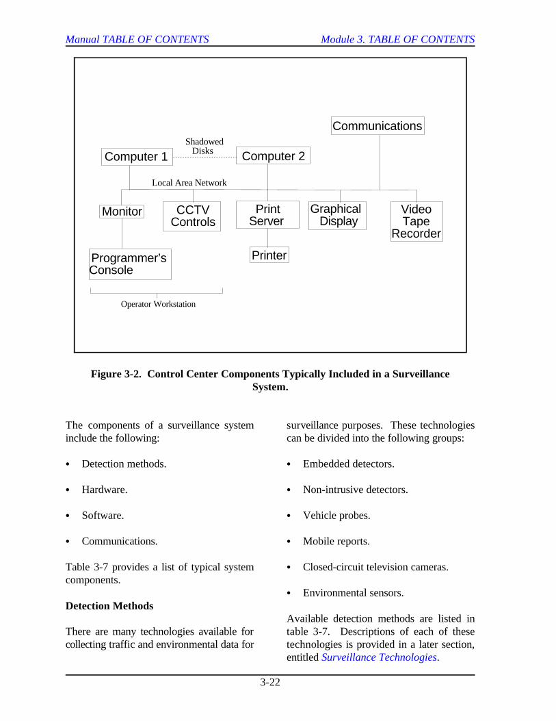
The complexity and size of a surveillancesystem will vary with the size of the freewaysystem being monitored and with the specificfunctions that it will perform. For example,when the area being surveyed is relativelysmall, a section of the traffic engineeringoffices may be sufficient to house the controlcenter. As the system expands and theresponsibilities of the control center increase,a larger center with more sophisticatedequipment may be required. Figure 3-2shows a simple example of the controlcenter components included in a surveillancesystem.
Computer 1 Computer 2
Communications
Monitor
Programmer’sConsole
PrintServer
GraphicalDisplay
VideoTape
Recorder
Shadowed Disks
Local Area Network
Printer
Operator Workstation
CCTVControls
Manual TABLE OF CONTENTS Module 3. TABLE OF CONTENTS
3-22
Figure 3-2. Control Center Components Typically Included in a SurveillanceSystem.
The components of a surveillance system surveillance purposes. These technologiesinclude the following: can be divided into the following groups:
C Detection methods. C Embedded detectors.
C Hardware. C Non-intrusive detectors.
C Software. C Vehicle probes.
C Communications. C Mobile reports.
Table 3-7 provides a list of typical system C Closed-circuit television cameras.components.
Detection Methods
There are many technologies available for table 3-7. Descriptions of each of thesecollecting traffic and environmental data for technologies is provided in a later section,
C Environmental sensors.
Available detection methods are listed in
entitled Surveillance Technologies.
Manual TABLE OF CONTENTS Module 3. TABLE OF CONTENTS
3-23
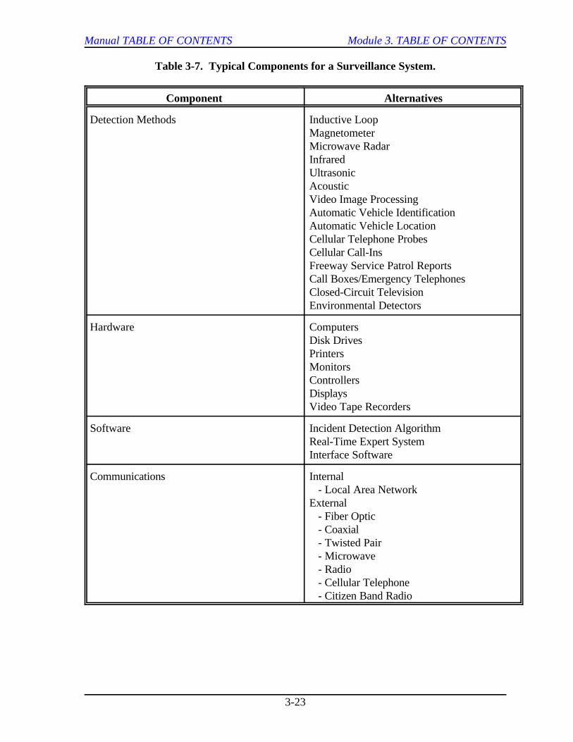
Table 3-7. Typical Components for a Surveillance System.
Component Alternatives
Detection Methods Inductive LoopMagnetometerMicrowave RadarInfraredUltrasonicAcousticVideo Image ProcessingAutomatic Vehicle IdentificationAutomatic Vehicle LocationCellular Telephone ProbesCellular Call-InsFreeway Service Patrol ReportsCall Boxes/Emergency TelephonesClosed-Circuit TelevisionEnvironmental Detectors
Hardware ComputersDisk DrivesPrintersMonitorsControllersDisplaysVideo Tape Recorders
Software Incident Detection AlgorithmReal-Time Expert SystemInterface Software
Communications Internal - Local Area NetworkExternal - Fiber Optic - Coaxial - Twisted Pair - Microwave - Radio - Cellular Telephone - Citizen Band Radio
Manual TABLE OF CONTENTS Module 3. TABLE OF CONTENTS
3-24
Hardware
Computers play significant roles in the may have software installed on the personaloperations of a surveillance system. The computer to control the cameras or mayfunctions performed by the computers in the have a separate control panel. Cameracontrol center include the following: controls usually include camera selection,(7)
C Reception of data transmission from thefield devices. The printers interface with the local area
C Transmission of data from the control use of print servers. Printers may be usedroom to the field equipment. to provide any of the following:
C Reception of operator commands from C Hard copy reports of mode status andkeyboards or control panels. equipment failure logs.
C Control of graphical displays. C Traffic data summaries.
C Data processing to perform such C Database status summaries.functions as detecting incidents, derivingtraffic flow characteristics, and C Special reports requested by theidentifying equipment failures. operator.
C Storing data to create a historical C Logs of system operations.database.
Computer 1 in figure 3-2 is an online provide observations of system operationscomputer that receives and transmits and camera field of views for CCTV.information to and from the field devices. Graphics may be provided on monitors at theComputer 2 serves as a backup and performs workstations or on a large screen graphicsoffline functions such as program display. The large screen displays havedevelopment and database updating. The generally replaced the wall map displayscomputers are typically microprocessor used in older centers. The display mayversions of minicomputers. The disk consist of a projection video display, a largeshadowing feature transfers data from the video screen, or an array of smaller videoonline computer to backup a system. screens. This new system has proven to be(4)
The operator workstation typically consists come online than the wall map system.of a personal computer unit. Functions thattake place at the workstation include Another important component of amonitoring traffic operations, incident surveillance system is the video tapedetection, decision making, and recorder. Traffic operations can be recordedimplementation of control strategies. for analyzing and comparing conditions over
Closed-circuit television (CCTV) can be purposes. Depending on the size of theused for monitoring traffic conditions or system and the recording requirements, onedetecting and confirming incidents. Controls or more recorders can be provided to
for operating the CCTV system are alsolocated at the workstation. The operator
pan, tilt, zoom, and focus.
network communication system through the
(4)
The functions of graphical displays are to
much easier to modify when new systems(4)
a given period of time or for demonstration
Manual TABLE OF CONTENTS Module 3. TABLE OF CONTENTS
3-25
interface with any camera in the system.(7)
Some traffic management centers choose notto record and archive incidents because of Real-time expert systems are currently beingthe potential drain on their staff (video tapes developed for application in traffic operationrequested by claims adjusters, lawyers, centers. These expert systems provideprivate citizens, etc.) and the possiblity of decision support for operations personnel sohaving to appear in court. they can more efficiently carry out their
Software
Software is an important component of a expert system include:surveillance system. Without software, thedata collected by the surveillance system has C Detecting, verifying, and estimating thelittle value. severity of incidents.
Three general types of software used with C Providing advice in areas such assurveillance systems include the following: dispatch of traffic and incident
C Software such as incident detectionalgorithms, etc. that apply the data C Developing and coordinating messagessupplied by the surveillance system on variable message signs and other
C Software that supports the operationssupport software such as real-time C Controlling traffic with lane control andknowledge-based systems. ramp control systems.
C Software for interfacing and The University of California at Irvine is incommunicating with the field devices. the process of developing a prototype real-
Incident Detection Algorithms
One of the primary objectives of a advanced processing capabilities to integratesurveillance system is to detect non- diverse types of traffic surveillance data forrecurring congestion, such as that caused by freeway monitoring and control purposes.an incident. Incidents cause significant After detecting an incident, the system usesamounts of delay for freeway vehicles; additional information from several sourceshowever, because they are random, they are to formulate appropriate responses. Theimpossible to predict and difficult to detect. information includes the following:Incident detection algorithms attempt toautomatically detect incidents based on field C Traffic data from detectors (e.g., speed,data received from detection equipment. volume, occupancy, etc.).Module 7 provides further discussion onincident detection algorithms.
Real-Time Expert Systems
functions. The knowledge-based support(8)
is based on the knowledge of experts in thefield of traffic management. Functions of an
(8, 9)
management teams.
methods of information dissemination.
time knowledge-based expert system calledFRED (Freeway Real-Time Expert SystemDemonstration). The expert system uses
(10)
C Information on traffic conditions fromCCTV.
C Field reports from police officers andother official personnel.
Manual TABLE OF CONTENTS Module 3. TABLE OF CONTENTS
3-26
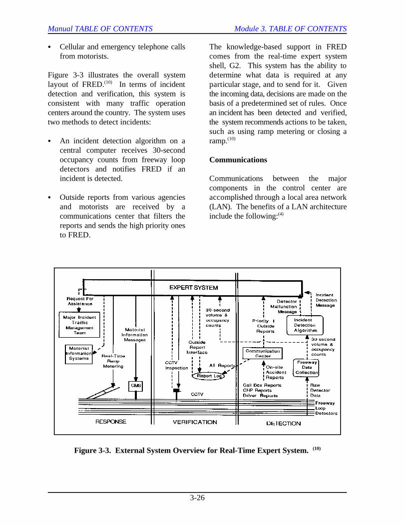
Figure 3-3. External System Overview for Real-Time Expert System. (10)
C Cellular and emergency telephone calls The knowledge-based support in FREDfrom motorists. comes from the real-time expert system
Figure 3-3 illustrates the overall system determine what data is required at anylayout of FRED. In terms of incident particular stage, and to send for it. Given(10)
detection and verification, this system is the incoming data, decisions are made on theconsistent with many traffic operation basis of a predetermined set of rules. Oncecenters around the country. The system uses an incident has been detected and verified,two methods to detect incidents: the system recommends actions to be taken,
C An incident detection algorithm on a ramp.central computer receives 30-secondoccupancy counts from freeway loopdetectors and notifies FRED if anincident is detected. Communications between the major
C Outside reports from various agencies accomplished through a local area networkand motorists are received by a (LAN). The benefits of a LAN architecturecommunications center that filters the include the following:reports and sends the high priority onesto FRED.
shell, G2. This system has the ability to
such as using ramp metering or closing a(10)
Communications
components in the control center are
(4)
Manual TABLE OF CONTENTS Module 3. TABLE OF CONTENTS
3-27
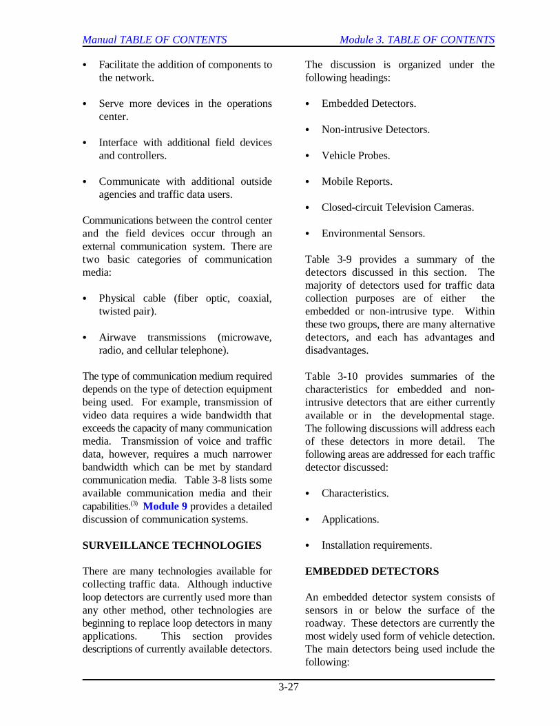
C Facilitate the addition of components to The discussion is organized under thethe network. following headings:
C Serve more devices in the operations C Embedded Detectors.center.
C Interface with additional field devicesand controllers. C Vehicle Probes.
C Communicate with additional outside C Mobile Reports.agencies and traffic data users.
Communications between the control centerand the field devices occur through an C Environmental Sensors.external communication system. There aretwo basic categories of communication Table 3-9 provides a summary of themedia: detectors discussed in this section. The
C Physical cable (fiber optic, coaxial, collection purposes are of either thetwisted pair). embedded or non-intrusive type. Within
C Airwave transmissions (microwave, detectors, and each has advantages andradio, and cellular telephone). disadvantages.
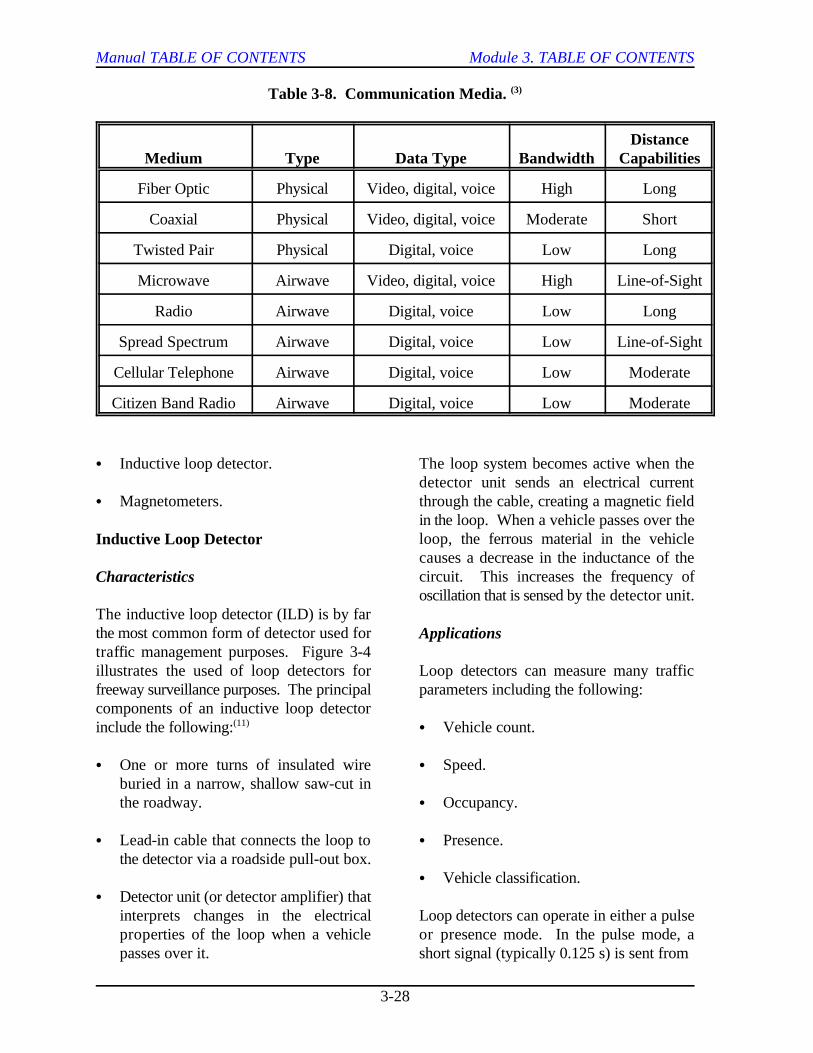
The type of communication medium requireddepends on the type of detection equipmentbeing used. For example, transmission ofvideo data requires a wide bandwidth thatexceeds the capacity of many communicationmedia. Transmission of voice and trafficdata, however, requires a much narrowerbandwidth which can be met by standardcommunication media. Table 3-8 lists someavailable communication media and theircapabilities. Module 9 provides a detailed(3)
discussion of communication systems. C Applications.
SURVEILLANCE TECHNOLOGIES
There are many technologies available forcollecting traffic data. Although inductiveloop detectors are currently used more than An embedded detector system consists ofany other method, other technologies are sensors in or below the surface of thebeginning to replace loop detectors in many roadway. These detectors are currently theapplications. This section provides most widely used form of vehicle detection.descriptions of currently available detectors. The main detectors being used include the
C Non-intrusive Detectors.
C Closed-circuit Television Cameras.
majority of detectors used for traffic data
these two groups, there are many alternative
Table 3-10 provides summaries of thecharacteristics for embedded and non-intrusive detectors that are either currentlyavailable or in the developmental stage.The following discussions will address eachof these detectors in more detail. Thefollowing areas are addressed for each trafficdetector discussed:
C Characteristics.
C Installation requirements.
EMBEDDED DETECTORS
following:
Manual TABLE OF CONTENTS Module 3. TABLE OF CONTENTS
3-28
Table 3-8. Communication Media. (3)
Medium Type Data Type Bandwidth CapabilitiesDistance
Fiber Optic Physical Video, digital, voice High Long
Coaxial Physical Video, digital, voice Moderate Short
Twisted Pair Physical Digital, voice Low Long
Microwave Airwave Video, digital, voice High Line-of-Sight
Radio Airwave Digital, voice Low Long
Spread Spectrum Airwave Digital, voice Low Line-of-Sight
Cellular Telephone Airwave Digital, voice Low Moderate
Citizen Band Radio Airwave Digital, voice Low Moderate
C Inductive loop detector. The loop system becomes active when the
C Magnetometers. through the cable, creating a magnetic field
Inductive Loop Detector
Characteristics
The inductive loop detector (ILD) is by farthe most common form of detector used fortraffic management purposes. Figure 3-4illustrates the used of loop detectors for Loop detectors can measure many trafficfreeway surveillance purposes. The principal parameters including the following:components of an inductive loop detectorinclude the following: C Vehicle count.(11)
C One or more turns of insulated wire C Speed.buried in a narrow, shallow saw-cut inthe roadway. C Occupancy.
C Lead-in cable that connects the loop to C Presence.the detector via a roadside pull-out box.
C Detector unit (or detector amplifier) thatinterprets changes in the electrical Loop detectors can operate in either a pulseproperties of the loop when a vehicle or presence mode. In the pulse mode, apasses over it. short signal (typically 0.125 s) is sent from
detector unit sends an electrical current
in the loop. When a vehicle passes over theloop, the ferrous material in the vehiclecauses a decrease in the inductance of thecircuit. This increases the frequency ofoscillation that is sensed by the detector unit.
Applications
C Vehicle classification.
Manual TABLE OF CONTENTS Module 3. TABLE OF CONTENTS
3-29
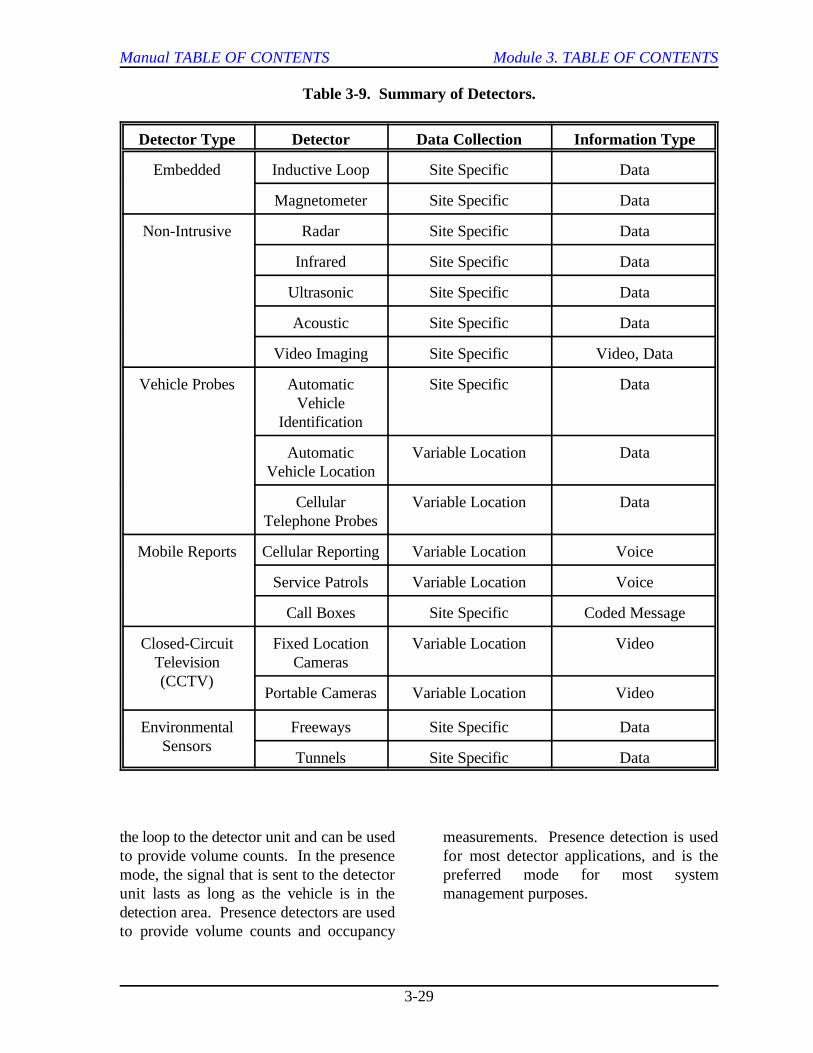
Table 3-9. Summary of Detectors.
Detector Type Detector Data Collection Information Type
Embedded Inductive Loop Site Specific Data
Magnetometer Site Specific Data
Non-Intrusive Radar Site Specific Data
Infrared Site Specific Data
Ultrasonic Site Specific Data
Acoustic Site Specific Data
Video Imaging Site Specific Video, Data
Vehicle Probes Automatic Site Specific DataVehicle
Identification
Automatic Variable Location DataVehicle Location
Cellular Variable Location DataTelephone Probes
Mobile Reports Cellular Reporting Variable Location Voice
Service Patrols Variable Location Voice
Call Boxes Site Specific Coded Message
Closed-Circuit Fixed Location Variable Location VideoTelevision Cameras(CCTV)
Portable Cameras Variable Location Video
Environmental Freeways Site Specific DataSensors
Tunnels Site Specific Data
the loop to the detector unit and can be used measurements. Presence detection is usedto provide volume counts. In the presence for most detector applications, and is themode, the signal that is sent to the detector preferred mode for most systemunit lasts as long as the vehicle is in the management purposes.detection area. Presence detectors are usedto provide volume counts and occupancy
Manual TA
BLE
OF
CO
NTE
NTS
Module 3. TA
BLE
OF
CO
NTE
NTS
3-30
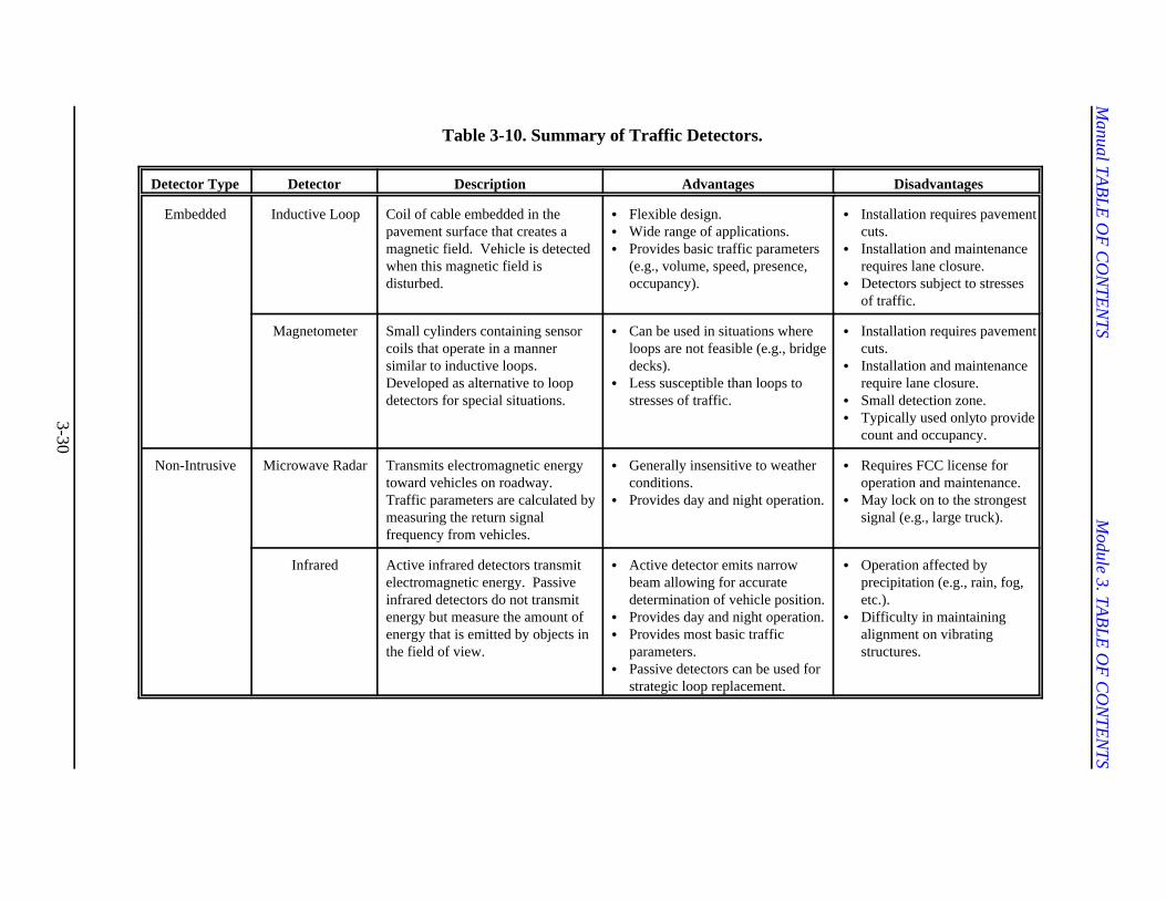
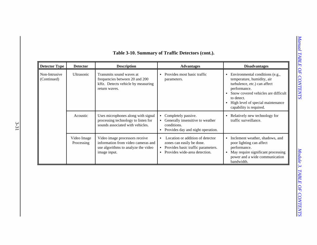
Table 3-10. Summary of Traffic Detectors.
Detector Type Detector Description Advantages Disadvantages
Embedded Inductive Loop Coil of cable embedded in thepavement surface that creates amagnetic field. Vehicle is detectedwhen this magnetic field isdisturbed.
C Flexible design.C Wide range of applications.C Provides basic traffic parameters
(e.g., volume, speed, presence,occupancy).
C Installation requires pavementcuts.
C Installation and maintenancerequires lane closure.
C Detectors subject to stressesof traffic.
Magnetometer Small cylinders containing sensorcoils that operate in a mannersimilar to inductive loops.Developed as alternative to loopdetectors for special situations.
C Can be used in situations whereloops are not feasible (e.g., bridgedecks).
C Less susceptible than loops tostresses of traffic.
C Installation requires pavementcuts.
C Installation and maintenancerequire lane closure.
C Small detection zone.C Typically used only to provide
count and occupancy.
Non-Intrusive Microwave Radar Transmits electromagnetic energytoward vehicles on roadway. Traffic parameters are calculated bymeasuring the return signalfrequency from vehicles.
C Generally insensitive to weatherconditions.
C Provides day and night operation.
C Requires FCC license foroperation and maintenance.
C May lock on to the strongestsignal (e.g., large truck).
Infrared Active infrared detectors transmitelectromagnetic energy. Passiveinfrared detectors do not transmitenergy but measure the amount ofenergy that is emitted by objects inthe field of view.
C Active detector emits narrowbeam allowing for accuratedetermination of vehicle position.
C Provides day and night operation.C Provides most basic traffic
parameters.C Passive detectors can be used for
strategic loop replacement.
C Operation affected byprecipitation (e.g., rain, fog,etc.).
C Difficulty in maintainingalignment on vibratingstructures.
Manual TA
BLE
OF
CO
NTE
NTS
Module 3. TA
BLE
OF
CO
NTE
NTS
3-31
Table 3-10. Summary of Traffic Detectors (cont.).
Detector Type Detector Description Advantages Disadvantages
Non-Intrusive(Continued)
Ultrasonic Transmits sound waves atfrequencies between 20 and 200kHz. Detects vehicle by measuringreturn waves.
C Provides most basic trafficparameters.
C Environmental conditions (e.g.,temperature, humidity, airturbulence, etc.) can affectperformance.
C Snow covered vehicles are difficultto detect.
C High level of special maintenancecapability is required.
Acoustic Uses microphones along with signalprocessing technology to listen forsounds associated with vehicles.
C Completely passive.C Generally insensitive to weather
conditions.C Provides day and night operation.
C Relatively new technology fortraffic surveillance.
Video ImageProcessing
Video image processors receiveinformation from video cameras anduse algorithms to analyze the videoimage input.
C Location or addition of detectorzones can easily be done.
C Provides basic traffic parameters.C Provides wide-area detection.
C Inclement weather, shadows, andpoor lighting can affectperformance.
C May require significant processingpower and a wide communicationbandwidth.
Manual TABLE OF CONTENTS Module 3. TABLE OF CONTENTS
3-32
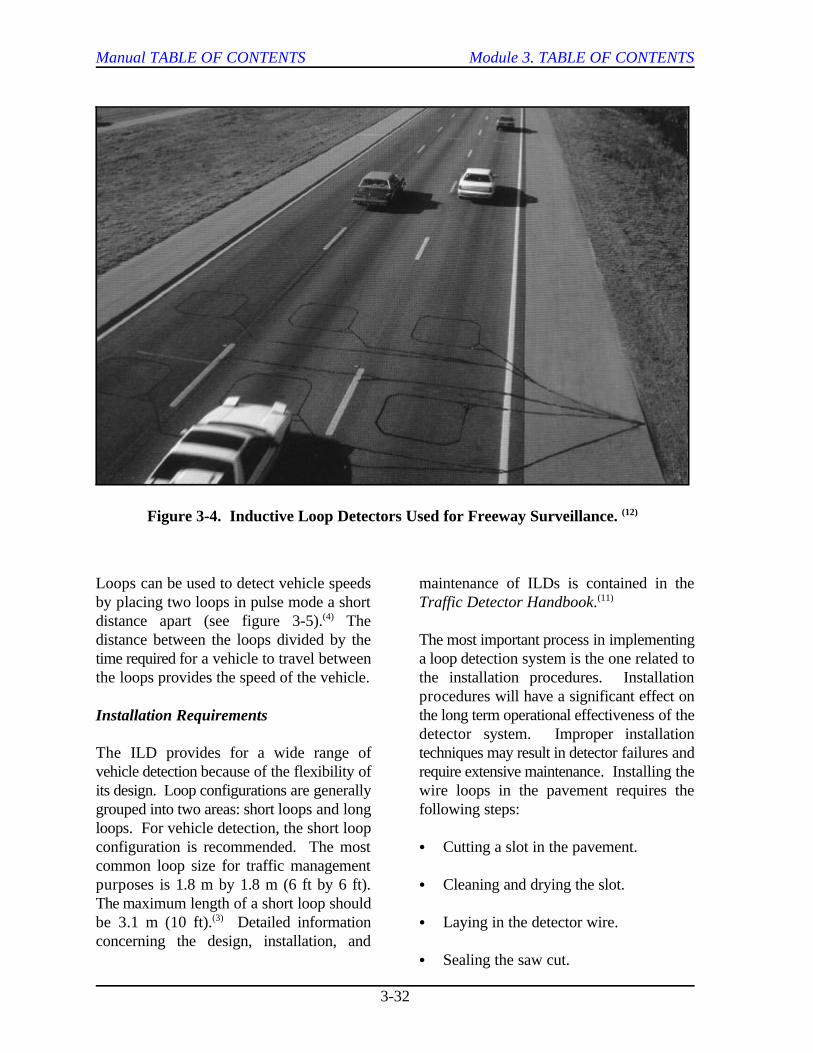
Figure 3-4. Inductive Loop Detectors Used for Freeway Surveillance. (12)
Loops can be used to detect vehicle speeds maintenance of ILDs is contained in theby placing two loops in pulse mode a short Traffic Detector Handbook.distance apart (see figure 3-5). The(4)
distance between the loops divided by the The most important process in implementingtime required for a vehicle to travel between a loop detection system is the one related tothe loops provides the speed of the vehicle. the installation procedures. Installation
Installation Requirements
The ILD provides for a wide range of techniques may result in detector failures andvehicle detection because of the flexibility of require extensive maintenance. Installing theits design. Loop configurations are generally wire loops in the pavement requires thegrouped into two areas: short loops and long following steps:loops. For vehicle detection, the short loopconfiguration is recommended. The most C Cutting a slot in the pavement.common loop size for traffic managementpurposes is 1.8 m by 1.8 m (6 ft by 6 ft). C Cleaning and drying the slot.The maximum length of a short loop shouldbe 3.1 m (10 ft). Detailed information C Laying in the detector wire.(3)
concerning the design, installation, and
(11)
procedures will have a significant effect onthe long term operational effectiveness of thedetector system. Improper installation
C Sealing the saw cut.
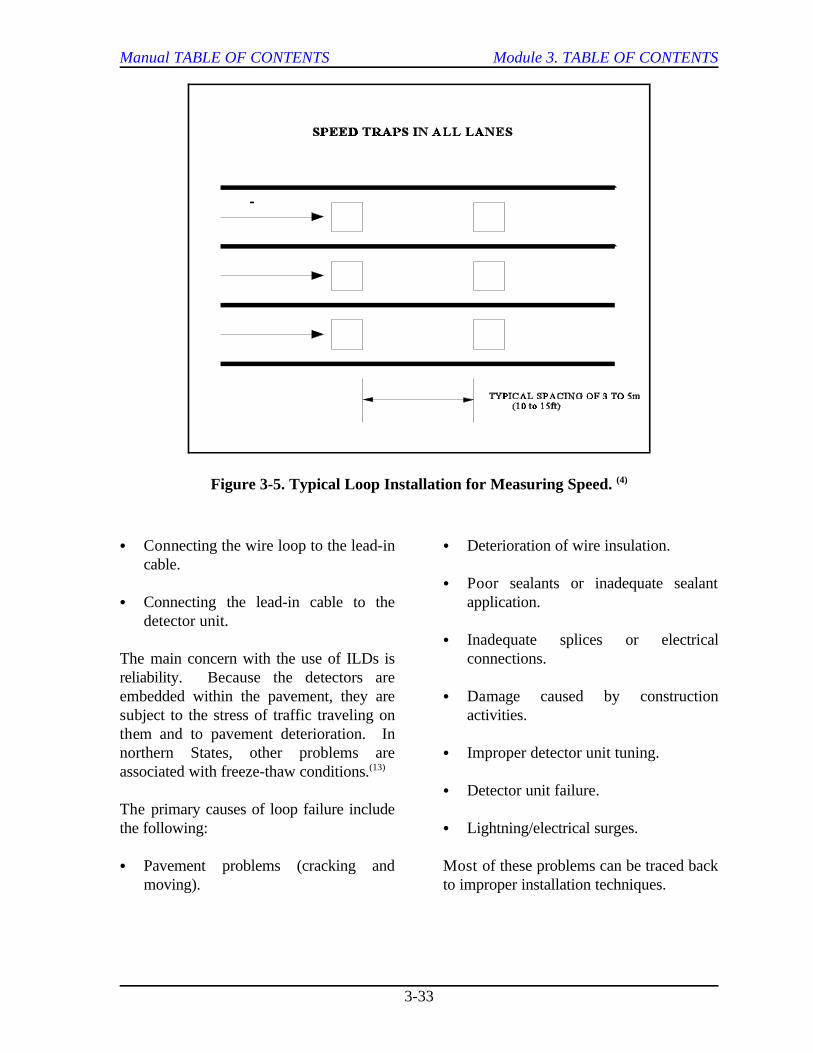
Manual TABLE OF CONTENTS Module 3. TABLE OF CONTENTS
3-33
Figure 3-5. Typical Loop Installation for Measuring Speed. (4)
C Connecting the wire loop to the lead-in C Deterioration of wire insulation.cable.
C Connecting the lead-in cable to the application.detector unit.
The main concern with the use of ILDs is connections.reliability. Because the detectors areembedded within the pavement, they are C Damage caused by constructionsubject to the stress of traffic traveling on activities.them and to pavement deterioration. Innorthern States, other problems are C Improper detector unit tuning.associated with freeze-thaw conditions. (13)
The primary causes of loop failure includethe following: C Lightning/electrical surges.
C Pavement problems (cracking and Most of these problems can be traced backmoving). to improper installation techniques.
C Poor sealants or inadequate sealant
C Inadequate splices or electrical
C Detector unit failure.
Manual TABLE OF CONTENTS Module 3. TABLE OF CONTENTS
3-34
Magnetometer Installation Requirements
Characteristics
Magnetometers contain small probes that pavement; however, because magnetometersrange in size from 5 cm (2 in) to 11 cm (4.25 are more compact in size, not as muchin) in diameter. The magnetometer was cutting is required. Detailed informationdeveloped as an alternative for loop concerning the design, installation, anddetectors in special situations, such as bridge maintenance of magnetometers is containedstructures. Figure 3-6 illustrates a typical in the Traffic Detector Handbook.installation for magnetometers. Similar toloop detectors, the components of a For a magnetometer to detect a vehicle,magnetometer detection system include the some part of the vehicle must pass over thefollowing: probe. Therefore, optimum lateral placement(11)
C One or more small probes (sensors) the following factors:embedded in the pavement.
C Probe cable. detected.
C Lead-in cable that connects the probe to C Width of lane.the detector via a roadside pull-out box.
C Detector unit.
Magnetometers measure the density of ft), a single probe might not be adequate forvertical flux lines of the earth’s magnetic lane widths greater than 3 m (10 ft). Forfield. When a vehicle passes over the probe, lane widths of 3.7 m (12 ft), two probes perthe ferrous material in the vehicle increases lane should be adequate for detecting allthe density of the flux lines. Magnetometers four-wheeled vehicles.sense this increase and interpret it as thepresence of a vehicle. Installing the magnetometers requires
Applications
Magnetometers can operate in eitherpresence of pulse modes and are most C Drill holes in pavement for probes.effective in determining occupancy andvolume. This type of system is usually used C Saw slots in pavement for detectorwhen the only information required is that a wires.vehicle has arrived at a specific point.(11)
Speed can also be measured by placing two C Clean and dry saw cuts.sets of probes a known distance apart.
Similar to the installation of inductive loops,installing magnetometers requires cutting the
(11)
of probes in the pavement is dependent upon
C Width of narrowest vehicle to be
C Required detection quality.
Since most vehicles are wider than 1.5 m (5
placing the detectors in the pavement. Theinstallation procedures include the followingsteps:
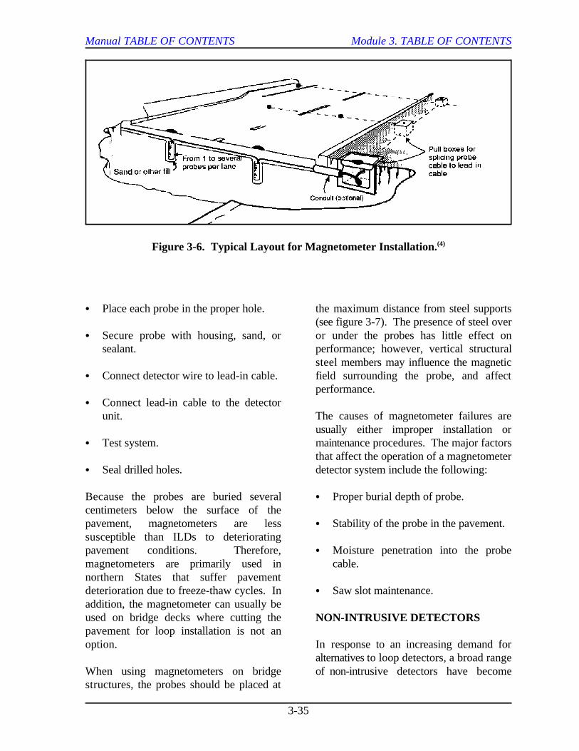
Manual TABLE OF CONTENTS Module 3. TABLE OF CONTENTS
3-35
Figure 3-6. Typical Layout for Magnetometer Installation.(4)
C Place each probe in the proper hole. the maximum distance from steel supports
C Secure probe with housing, sand, or or under the probes has little effect onsealant. performance; however, vertical structural
C Connect detector wire to lead-in cable. field surrounding the probe, and affect
C Connect lead-in cable to the detectorunit. The causes of magnetometer failures are
C Test system. maintenance procedures. The major factors
C Seal drilled holes. detector system include the following:
Because the probes are buried several C Proper burial depth of probe.centimeters below the surface of thepavement, magnetometers are less C Stability of the probe in the pavement.susceptible than ILDs to deterioratingpavement conditions. Therefore, C Moisture penetration into the probemagnetometers are primarily used in cable.northern States that suffer pavementdeterioration due to freeze-thaw cycles. In C Saw slot maintenance.addition, the magnetometer can usually beused on bridge decks where cutting thepavement for loop installation is not anoption. In response to an increasing demand for
When using magnetometers on bridge of non-intrusive detectors have becomestructures, the probes should be placed at
(see figure 3-7). The presence of steel over
steel members may influence the magnetic
performance.
usually either improper installation or
that affect the operation of a magnetometer
NON-INTRUSIVE DETECTORS
alternatives to loop detectors, a broad range
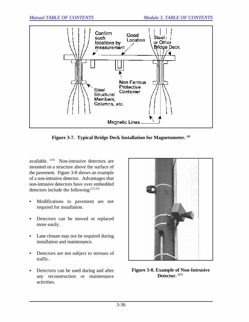
Manual TABLE OF CONTENTS Module 3. TABLE OF CONTENTS
3-36
Figure 3-7. Typical Bridge Deck Installation for Magnetometer. (4)
Figure 3-8. Example of Non-IntrusiveDetector. (17)
available. Non-intrusive detectors are(14)
mounted on a structure above the surface ofthe pavement. Figure 3-8 shows an exampleof a non-intrusive detector. Advantages thatnon-intrusive detectors have over embeddeddetectors include the following:(15,16)
C Modifications to pavement are notrequired for installation.
C Detectors can be moved or replacedmore easily.
C Lane closure may not be required duringinstallation and maintenance.
C Detectors are not subject to stresses oftraffic.
C Detectors can be used during and afterany reconstruction or maintenanceactivities.
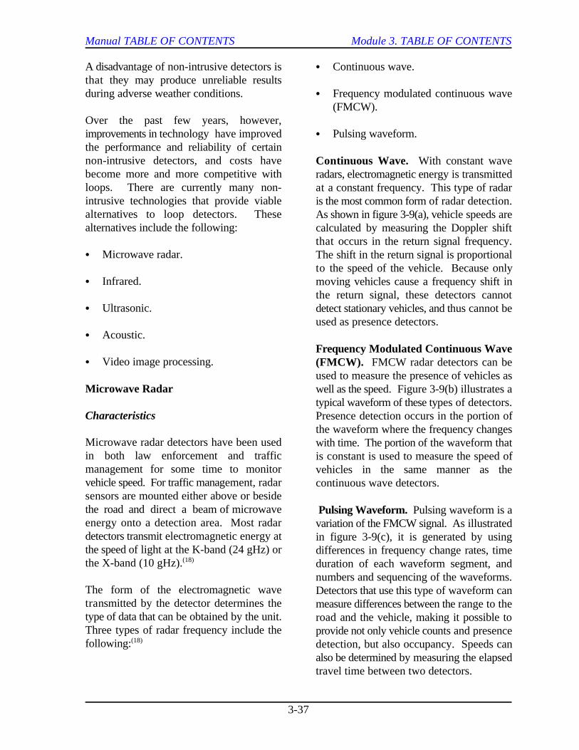
Manual TABLE OF CONTENTS Module 3. TABLE OF CONTENTS
3-37
A disadvantage of non-intrusive detectors is C Continuous wave.that they may produce unreliable resultsduring adverse weather conditions. C Frequency modulated continuous wave
Over the past few years, however,improvements in technology have improved C Pulsing waveform.the performance and reliability of certainnon-intrusive detectors, and costs havebecome more and more competitive withloops. There are currently many non-intrusive technologies that provide viablealternatives to loop detectors. Thesealternatives include the following:
C Microwave radar.
C Infrared.
C Ultrasonic.
C Acoustic.
C Video image processing.
Microwave Radar
Characteristics
Microwave radar detectors have been usedin both law enforcement and trafficmanagement for some time to monitorvehicle speed. For traffic management, radarsensors are mounted either above or besidethe road and direct a beam of microwaveenergy onto a detection area. Most radardetectors transmit electromagnetic energy atthe speed of light at the K-band (24 gHz) orthe X-band (10 gHz).(18)
The form of the electromagnetic wavetransmitted by the detector determines thetype of data that can be obtained by the unit.Three types of radar frequency include thefollowing:(18)
(FMCW).
Continuous Wave. With constant waveradars, electromagnetic energy is transmittedat a constant frequency. This type of radaris the most common form of radar detection.As shown in figure 3-9(a), vehicle speeds arecalculated by measuring the Doppler shiftthat occurs in the return signal frequency.The shift in the return signal is proportionalto the speed of the vehicle. Because onlymoving vehicles cause a frequency shift inthe return signal, these detectors cannotdetect stationary vehicles, and thus cannot beused as presence detectors.
Frequency Modulated Continuous Wave(FMCW). FMCW radar detectors can beused to measure the presence of vehicles aswell as the speed. Figure 3-9(b) illustrates atypical waveform of these types of detectors.Presence detection occurs in the portion ofthe waveform where the frequency changeswith time. The portion of the waveform thatis constant is used to measure the speed ofvehicles in the same manner as thecontinuous wave detectors.
Pulsing Waveform. Pulsing waveform is avariation of the FMCW signal. As illustratedin figure 3-9(c), it is generated by usingdifferences in frequency change rates, timeduration of each waveform segment, andnumbers and sequencing of the waveforms.Detectors that use this type of waveform canmeasure differences between the range to theroad and the vehicle, making it possible toprovide not only vehicle counts and presencedetection, but also occupancy. Speeds canalso be determined by measuring the elapsedtravel time between two detectors.
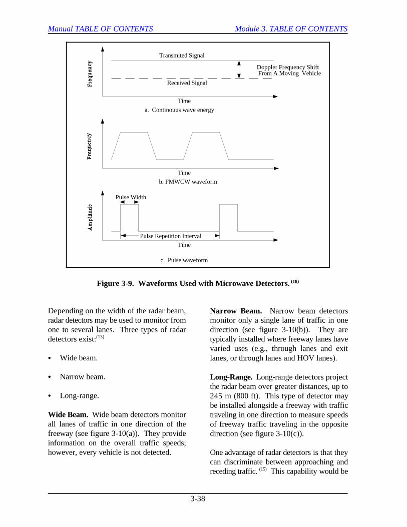
Pulse Repetition Interval
Doppler Frequency Shift From A Moving Vehicle
Transmited Signal
Received Signal
a. Continouus wave energy
b. FMWCW waveform
Time
Time
Time
Pulse Width
c. Pulse waveform
Manual TABLE OF CONTENTS Module 3. TABLE OF CONTENTS
3-38
Figure 3-9. Waveforms Used with Microwave Detectors. (18)
Depending on the width of the radar beam,radar detectors may be used to monitor from monitor only a single lane of traffic in oneone to several lanes. Three types of radar direction (see figure 3-10(b)). They aredetectors exist: typically installed where freeway lanes have(13)
C Wide beam.
C Narrow beam.
C Long-range.
Wide Beam. Wide beam detectors monitorall lanes of traffic in one direction of thefreeway (see figure 3-10(a)). They provideinformation on the overall traffic speeds;however, every vehicle is not detected.
Narrow Beam. Narrow beam detectors
varied uses (e.g., through lanes and exitlanes, or through lanes and HOV lanes).
Long-Range. Long-range detectors projectthe radar beam over greater distances, up to245 m (800 ft). This type of detector maybe installed alongside a freeway with traffictraveling in one direction to measure speedsof freeway traffic traveling in the oppositedirection (see figure 3-10(c)).
One advantage of radar detectors is that theycan discriminate between approaching andreceding traffic. This capability would be(15)
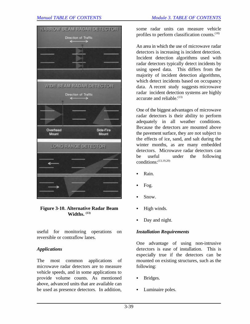
Manual TABLE OF CONTENTS Module 3. TABLE OF CONTENTS
3-39
Figure 3-10. Alternative Radar BeamWidths. (13)
useful for monitoring operations onreversible or contraflow lanes.
Applications
The most common applications of mounted on existing structures, such as themicrowave radar detectors are to measure following:vehicle speeds, and in some applications toprovide volume counts. As mentioned C Bridges.above, advanced units that are available canbe used as presence detectors. In addition, C Luminaire poles.
some radar units can measure vehicleprofiles to perform classification counts.(18)
An area in which the use of microwave radardetectors is increasing is incident detection.Incident detection algorithms used withradar detectors typically detect incidents byusing speed data. This differs from themajority of incident detection algorithms,which detect incidents based on occupancydata. A recent study suggests microwaveradar incident detection systems are highlyaccurate and reliable.(13)
One of the biggest advantages of microwaveradar detectors is their ability to performadequately in all weather conditions.Because the detectors are mounted abovethe pavement surface, they are not subject tothe effects of ice, sand, and salt during thewinter months, as are many embeddeddetectors. Microwave radar detectors canbe useful under the followingconditions:(13,19,20)
C Rain.
C Fog.
C Snow.
C High winds.
C Day and night.
Installation Requirements
One advantage of using non-intrusivedetectors is ease of installation. This isespecially true if the detectors can be

Manual TABLE OF CONTENTS Module 3. TABLE OF CONTENTS
3-40
C Sign structures. C Difficulties of maintaining alignment on
Radar detectors can be mounted in either theside-fire position (see figure 3-11) or the C Inconsistent beam patterns caused byoverhead position (see figure 3-12). Setup changes in infrared energy levels due toof the detector is simple and involves simply passing clouds, shadows, fog, andaiming the unit at the traffic flow. Unlike precipitation.other detection systems, most current radarunits do not require setup, configuration, or C Lenses used in some devices may becalibration to provide accurate data. sensitive to moisture, dust, or other(13)
Maintenance costs of radar detectors havealso proven to be relatively low. One study C Inconsistent reliability under high volumeconducted in a northern State showed only a conditions.2 percent failure rate for radar detectors over2 years. This compares with a 34 percent An advantage of active infrared detectors isfailure rate of loop detectors over a 5-year the very narrow beam width that they emit.period. Costs are also kept lower, This allows for accurate determination of the(13)
because maintenance of the detectors spatial position of a vehicle on a road. Intypically does not require lane closure on the addition, the profile of a vehicle can befreeway. measured to within a few centimeters for
Infrared
Characteristics figure 3-14) do not transmit energy
There are two types of infrared detectors:
C Active.
C Passive.
Active. Active infrared detectors (see figure been used as motion detectors; however,3-13) operate by directing a narrow beam of detectors are currently available forenergy toward a background, such as the detecting presence as well. As with activesurface of a roadway, at a certain pulse rate. infrared detectors, the ability of passiveA portion of the beam is directed back to the sensors to detect vehicles can be affected bysensor, and vehicles are detected by changes environmental effects, such as fog andin the characteristics of the infrared beam. precipitation, that can scatter and emitThe infrared beam can be transmitted from energy of their own. one side of the road to the other, or from anoverhead or roadside position to a device inthe pavement surface. Disadvantages ofactive infrared sensors include thefollowing:(3)
vibrating structures.
contaminants.
some systems.(22)
Passive. Passive infrared detectors (see
themselves, but measure the amount ofenergy that is emitted by objects in the fieldof view. The amount of energy that isemitted by an object depends on its surfacetemperature, size, and structure, but not onits color or the surrounding lightingconditions. For years, these detectors have
(14)
(18)
Applications
Active. Currently available active infrareddetectors can provide speed, count, density,and vehicle classification. Accuracy is based
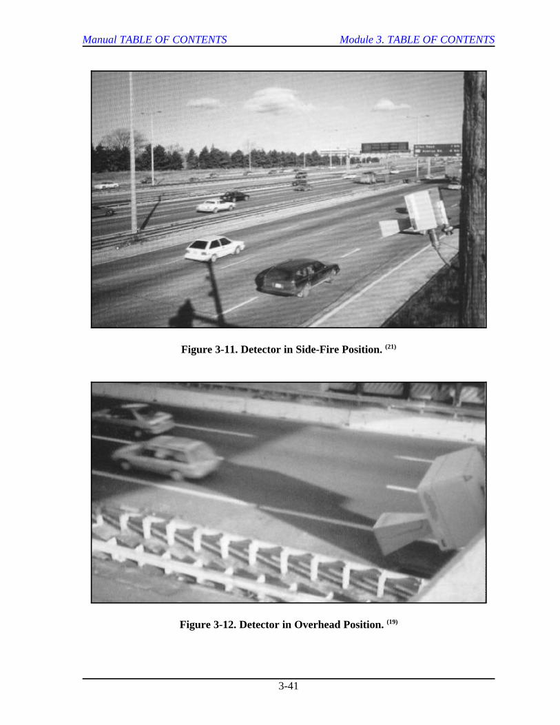
Manual TABLE OF CONTENTS Module 3. TABLE OF CONTENTS
3-41
Figure 3-11. Detector in Side-Fire Position. (21)
Figure 3-12. Detector in Overhead Position. (19)
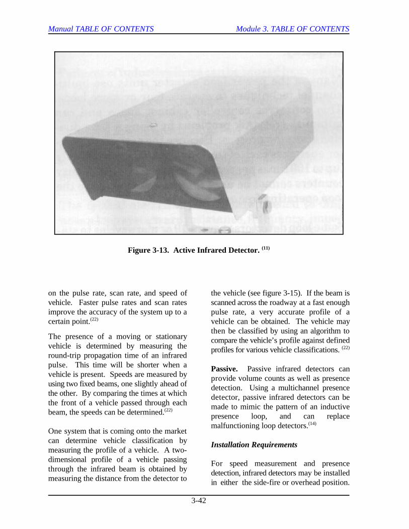
Manual TABLE OF CONTENTS Module 3. TABLE OF CONTENTS
3-42
Figure 3-13. Active Infrared Detector. (11)
on the pulse rate, scan rate, and speed of the vehicle (see figure 3-15). If the beam isvehicle. Faster pulse rates and scan rates scanned across the roadway at a fast enoughimprove the accuracy of the system up to a pulse rate, a very accurate profile of acertain point. vehicle can be obtained. The vehicle may(22)
The presence of a moving or stationaryvehicle is determined by measuring theround-trip propagation time of an infraredpulse. This time will be shorter when avehicle is present. Speeds are measured byusing two fixed beams, one slightly ahead ofthe other. By comparing the times at whichthe front of a vehicle passed through eachbeam, the speeds can be determined.(22)
One system that is coming onto the marketcan determine vehicle classification bymeasuring the profile of a vehicle. A two-dimensional profile of a vehicle passingthrough the infrared beam is obtained bymeasuring the distance from the detector to
then be classified by using an algorithm tocompare the vehicle’s profile against definedprofiles for various vehicle classifications. (22)
Passive. Passive infrared detectors canprovide volume counts as well as presencedetection. Using a multichannel presencedetector, passive infrared detectors can bemade to mimic the pattern of an inductivepresence loop, and can replacemalfunctioning loop detectors.(14)
Installation Requirements
For speed measurement and presencedetection, infrared detectors may be installedin either the side-fire or overhead position.
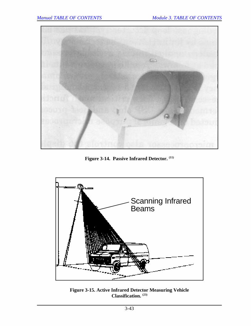
Scanning InfraredBeams
Manual TABLE OF CONTENTS Module 3. TABLE OF CONTENTS
3-43
Figure 3-14. Passive Infrared Detector. (11)
Figure 3-15. Active Infrared Detector Measuring VehicleClassification. (23)
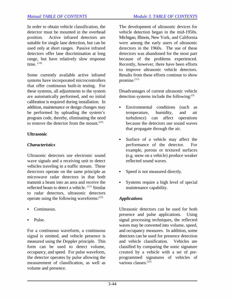
Manual TABLE OF CONTENTS Module 3. TABLE OF CONTENTS
3-44
In order to obtain vehicle classification, the The development of ultrasonic devices fordetector must be mounted in the overhead vehicle detection began in the mid-1950s.position. Active infrared detectors are Michigan, Illinois, New York, and Californiasuitable for single lane detection, but can be were among the early users of ultrasonicused only at short ranges. Passive infrared detectors in the 1960s. The use of thesedetectors offer lane discrimination at long detectors was abandoned for the most partrange, but have relatively slow response because of the problems experienced.time. Recently, however, there have been efforts(14)
Some currently available active infrared Results from these efforts continue to showsystems have incorporated microcontrollers promise.that offer continuous built-in testing. Forthese systems, all adjustments to the system Disadvantages of current ultrasonic vehicleare automatically performed, and no initial detection systems include the following:calibration is required during installation. Inaddition, maintenance or design changes may C Environmental conditions (such asbe performed by uploading the system’s temperature, humidity, and airprogram code, thereby, eliminating the need turbulence) can affect operationsto remove the detector from the mount. because the detectors use sound waves(22)
Ultrasonic
Characteristics
Ultrasonic detectors use electronic sound (e.g. snow on a vehicle) produce weakerwave signals and a receiving unit to detect reflected sound waves.vehicles traveling in a traffic stream. Thesedetectors operate on the same principle as C Speed is not measured directly.microwave radar detectors in that bothtransmit a beam into an area and receive the C Systems require a high level of specialreflected beam to detect a vehicle. Similar maintenance capability.(11)
to radar detectors, ultrasonic detectorsoperate using the following waveforms:(22)
C Continuous. Ultrasonic detectors can be used for both
C Pulse. signal processing techniques, the reflected
For a continuous waveform, a continuous and occupancy measures. In addition, somesignal is emitted, and vehicle presence is detectors can be used for presence detectionmeasured using the Doppler principle. This and vehicle classification. Vehicles areform can be used to detect volume, classified by comparing the sonic signatureoccupancy, and speed. For pulse waveform, created by a vehicle with a set of pre-the detector operates by pulse allowing the programmed signatures of vehicles ofmeasurement of classification, as well as various classes.volume and presence.
to improve ultrasonic vehicle detectors.
(11)
(3)
that propagate through the air.
C Surface of a vehicle may affect theperformance of the detector. Forexample, porous or textured surfaces
Applications
presence and pulse applications. Using
waves may be converted into volume, speed,
(22)
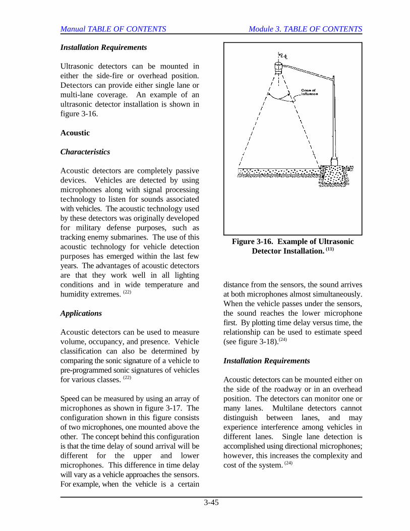
Manual TABLE OF CONTENTS Module 3. TABLE OF CONTENTS
3-45
Figure 3-16. Example of UltrasonicDetector Installation. (11)
Installation Requirements
Ultrasonic detectors can be mounted ineither the side-fire or overhead position.Detectors can provide either single lane ormulti-lane coverage. An example of anultrasonic detector installation is shown infigure 3-16.
Acoustic
Characteristics
Acoustic detectors are completely passivedevices. Vehicles are detected by usingmicrophones along with signal processingtechnology to listen for sounds associatedwith vehicles. The acoustic technology usedby these detectors was originally developedfor military defense purposes, such astracking enemy submarines. The use of thisacoustic technology for vehicle detectionpurposes has emerged within the last fewyears. The advantages of acoustic detectorsare that they work well in all lightingconditions and in wide temperature and distance from the sensors, the sound arriveshumidity extremes. at both microphones almost simultaneously.(22)
Applications
Acoustic detectors can be used to measure relationship can be used to estimate speedvolume, occupancy, and presence. Vehicle (see figure 3-18).classification can also be determined bycomparing the sonic signature of a vehicle topre-programmed sonic signatures of vehiclesfor various classes. Acoustic detectors can be mounted either on(22)
Speed can be measured by using an array of position. The detectors can monitor one ormicrophones as shown in figure 3-17. The many lanes. Multilane detectors cannotconfiguration shown in this figure consists distinguish between lanes, and mayof two microphones, one mounted above the experience interference among vehicles inother. The concept behind this configuration different lanes. Single lane detection isis that the time delay of sound arrival will be accomplished using directional microphones;different for the upper and lower however, this increases the complexity andmicrophones. This difference in time delay cost of the system.will vary as a vehicle approaches the sensors.For example, when the vehicle is a certain
When the vehicle passes under the sensors,the sound reaches the lower microphonefirst. By plotting time delay versus time, the
(24)
Installation Requirements
the side of the roadway or in an overhead
(24)
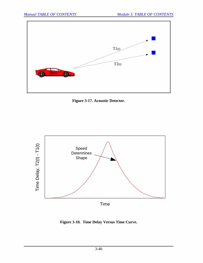
T1(t)
T2(t)
0
200
400
600
800
1000
1200
1400
Tim
e D
elay
, T2(
t) -
T1(
t)
0 5 10 15 20
Time
SpeedDetermines
Shape
Manual TABLE OF CONTENTS Module 3. TABLE OF CONTENTS
3-46
Figure 3-17. Acoustic Detector.
Figure 3-18. Time Delay Versus Time Curve.
Manual TABLE OF CONTENTS Module 3. TABLE OF CONTENTS
3-47
Video Image Processing Tripline. These first generation systems are
Characteristics power and speed. Most of the VIP systems
An emerging technology that appears to bevery promising for meeting future datacollection and surveillance needs is known asvideo image processing (VIP). VIP systemsdetect vehicles by monitoring specific pointsin the video image of a traffic scene todetermine changes between successiveframes. The components of a VIP system(25)
are shown in figure 3-19. Most systemsconsist of the following major elements:
C One or more video cameras.
C Microprocessor-based system forprocessing the video image.
C Software for interpreting the processedimages as vehicle detections.
The microprocessor-based system receivesvideo inputs from the cameras. Afterreceiving video input, the processor analyzesthe variation of gray levels in a series ofpixels from the video image. The processormust filter out gray level variations resultingfrom weather conditions, shadows, and day-or night-time-related aspects. The resultingimage consists of a blank backgroundcontaining only identified objects such asvehicles, motorcycles, and/or bicycles. Byanalyzing successive video frames, thesystem is able to calculate vehicle-relatedinformation.(20)
Classes of VIP Systems. VIP systems haveevolved through the following three classes:
C Tripline.
C Closed Loop Tracking.
C Data Association Tracking.
the least demanding in terms of computer
that are commercially available at this timeare of this class. Tripline systems operate byallowing the user to define a limited numberof detection zones in the field of view of thevideo camera. When a vehicle enters one ofthese detection zones, it is identified in amanner analogous to that of inductive loops.In fact, tripline systems are the functionalequivalent of inductive loops and areintended to replace inductive loops in areaswhere a large number of loops are employed.Limitations of tripline systems include thefollowing:
C Difficulty in detection due to thepresence of shadows or light changingconditions.
C Problems of occlusion (vehicle hidden byanother vehicle or object).
Closed Loop Tracking. These systems aresecond generation VIP systems. They are anextension of the tripline approach in thatdetection is performed using the same typeof detection zones. Closed loop trackingsystems represent the first attempt toperform vehicle tracking. These systemshave the same problems as tripline systemswith shadows and occlusion. They providemore traffic flow information than triplinesystems, but the complexity of bothhardware and software subsystems issignificantly greater than for tripline systems.
Data Association Tracking. These systems,commonly used in satellite surveillancesystems, are third generation VIP systems.A basic requirement for these systems is thecapability to identify and track adistinguishable object as it passes throughthe field of view of the camera. In thismode, the computer identifies vehicles by
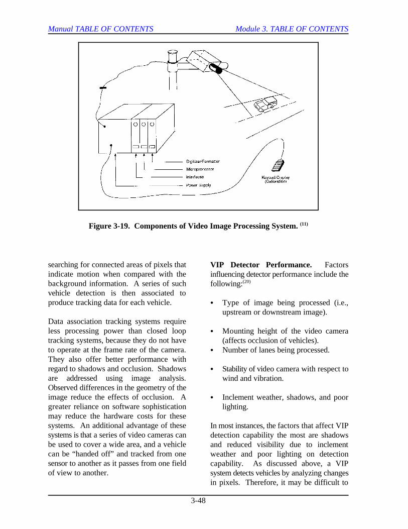
Manual TABLE OF CONTENTS Module 3. TABLE OF CONTENTS
3-48
Figure 3-19. Components of Video Image Processing System. (11)
searching for connected areas of pixels thatindicate motion when compared with thebackground information. A series of suchvehicle detection is then associated toproduce tracking data for each vehicle.
Data association tracking systems requireless processing power than closed looptracking systems, because they do not haveto operate at the frame rate of the camera.They also offer better performance withregard to shadows and occlusion. Shadowsare addressed using image analysis.Observed differences in the geometry of theimage reduce the effects of occlusion. Agreater reliance on software sophisticationmay reduce the hardware costs for thesesystems. An additional advantage of thesesystems is that a series of video cameras canbe used to cover a wide area, and a vehiclecan be “handed off” and tracked from onesensor to another as it passes from one fieldof view to another.
VIP Detector Performance. Factorsinfluencing detector performance include thefollowing:(20)
C Type of image being processed (i.e.,upstream or downstream image).
C Mounting height of the video camera(affects occlusion of vehicles).
C Number of lanes being processed.
C Stability of video camera with respect towind and vibration.
C Inclement weather, shadows, and poorlighting.
In most instances, the factors that affect VIPdetection capability the most are shadowsand reduced visibility due to inclementweather and poor lighting on detectioncapability. As discussed above, a VIPsystem detects vehicles by analyzing changesin pixels. Therefore, it may be difficult to
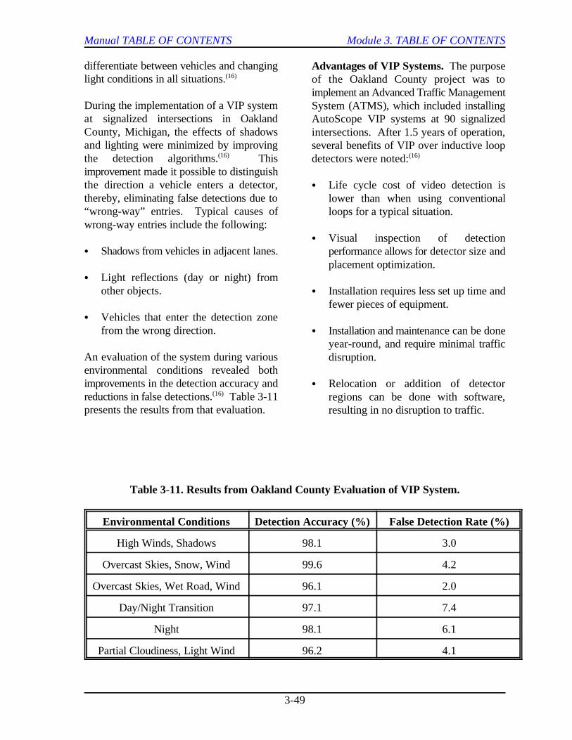
Manual TABLE OF CONTENTS Module 3. TABLE OF CONTENTS
3-49
differentiate between vehicles and changinglight conditions in all situations.(16)
During the implementation of a VIP systemat signalized intersections in OaklandCounty, Michigan, the effects of shadowsand lighting were minimized by improvingthe detection algorithms. This(16)
improvement made it possible to distinguishthe direction a vehicle enters a detector,thereby, eliminating false detections due to“wrong-way” entries. Typical causes ofwrong-way entries include the following:
C Shadows from vehicles in adjacent lanes.
C Light reflections (day or night) fromother objects.
C Vehicles that enter the detection zonefrom the wrong direction.
An evaluation of the system during variousenvironmental conditions revealed bothimprovements in the detection accuracy andreductions in false detections. Table 3-11(16)
presents the results from that evaluation.
Advantages of VIP Systems. The purposeof the Oakland County project was toimplement an Advanced Traffic ManagementSystem (ATMS), which included installingAutoScope VIP systems at 90 signalizedintersections. After 1.5 years of operation,several benefits of VIP over inductive loopdetectors were noted:(16)
C Life cycle cost of video detection islower than when using conventionalloops for a typical situation.
C Visual inspection of detectionperformance allows for detector size andplacement optimization.
C Installation requires less set up time andfewer pieces of equipment.
C Installation and maintenance can be doneyear-round, and require minimal trafficdisruption.
C Relocation or addition of detectorregions can be done with software,resulting in no disruption to traffic.
Table 3-11. Results from Oakland County Evaluation of VIP System.
Environmental Conditions Detection Accuracy (%) False Detection Rate (%)
High Winds, Shadows 98.1 3.0
Overcast Skies, Snow, Wind 99.6 4.2
Overcast Skies, Wet Road, Wind 96.1 2.0
Day/Night Transition 97.1 7.4
Night 98.1 6.1
Partial Cloudiness, Light Wind 96.2 4.1
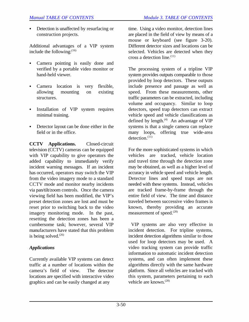
Manual TABLE OF CONTENTS Module 3. TABLE OF CONTENTS
3-50
C Detection is unaffected by resurfacing or time. Using a video monitor, detection linesconstruction projects. are placed in the field of view by means of a
Additional advantages of a VIP system Different detector sizes and locations can beinclude the following: selected. Vehicles are detected when they(16)
C Camera pointing is easily done andverified by a portable video monitor or The processing system of a tripline VIPhand-held viewer. system provides outputs comparable to those
C Camera location is very flexible, include presence and passage as well asallowing mounting on existing speed. From these measurements, otherstructures. traffic parameters can be extracted, including
C Installation of VIP system requires detectors, speed trap detectors can extractminimal training. vehicle speed and vehicle classifications as
C Detector layout can be done either in the systems is that a single camera can replacefield or in the office. many loops, offering true wide-area
CCTV Applications. Closed-circuittelevision (CCTV) cameras can be equippedwith VIP capability to give operators theadded capability to immediately verifyincident warning messages. If an incidenthas occurred, operators may switch the VIPfrom the video imagery mode to a standardCCTV mode and monitor nearby incidentsvia pan/tilt/zoom controls. Once the cameraviewing field has been modified, the VIP’spreset detection zones are lost and must bereset prior to switching back to the videoimagery monitoring mode. In the past,resetting the detection zones has been acumbersome task; however, several VIPmanufacturers have stated that this problemis being solved.(26)
Applications
Currently available VIP systems can detecttraffic at a number of locations within thecamera’s field of view. The detectorlocations are specified with interactive videographics and can be easily changed at any
mouse or keyboard (see figure 3-20).
cross a detection line.(11)
provided by loop detectors. These outputs
volume and occupancy. Similar to loop
defined by length. An advantage of VIP(4)
detection.(11)
For the more sophisticated systems in whichvehicles are tracked, vehicle locationand travel time through the detection zonemay be obtained, as well as a higher level ofaccuracy in vehicle speed and vehicle length.Detector lines and speed traps are notneeded with these systems. Instead, vehiclesare tracked frame-by-frame through theentire field of view. The time and distancetraveled between successive video frames isknown, thereby providing an accuratemeasurement of speed.(28)
VIP systems are also very effective inincident detection. For tripline systems,incident detection algorithms similar to thoseused for loop detectors may be used. Avideo tracking system can provide trafficinformation to automatic incident detectionsystems, and can often implement thesealgorithms directly with the same hardwareplatform. Since all vehicles are tracked withthis system, parameters pertaining to eachvehicle are known.(28)
Manual TABLE OF CONTENTS Module 3. TABLE OF CONTENTS
3-51
Figure 3-20. Identification of Detection Lines in Field of View.
Installation Requirements COMPARISON OF EMBEDDED AND
The video detection system includes thefollowing elements: A summary of the advantages and
C Roadside cameras. discussed was given toward the beginning of
C Video processor. the functional capabilities of the various
C Appropriate software. detector costs. These estimates will vary by
The cameras are mounted above theroadway, typically on existing poles, bridges,or other structures. Occlusion caused byother vehicles or objects can be minimized With the recent advances in computer,by selecting proper camera location and communications, and vehicle locatingdefining optimal detector sizing. technologies, the vehicle itself can become(28)
Some existing VIP systems offer complete traffic conditions in the roadway network.fail-safe operation. For example, each Vehicles, acting as moving sensors (orcamera is monitored for video signal quality probes), can provide information aboutand picture usability. If a camera fails, the traffic conditions on each link traversed.affected detection zones will be switched to This information can be transmitted to aa user-defined mode, such as “always on.” central computer system where it can then beThe nature of the problem is also reported to merged with information from other sourcesoperators in the traffic control center. to provide an accurate representation of(28)
NON-INTRUSIVE DETECTORS
disadvantages of each of the systems
this section (see table 3-10). Table 3-12 lists
systems, as well as estimated installation and
manufacturer and quantity purchased.
VEHICLE PROBES
an important surveillance tool for monitoring
actual travel conditions in the transportation
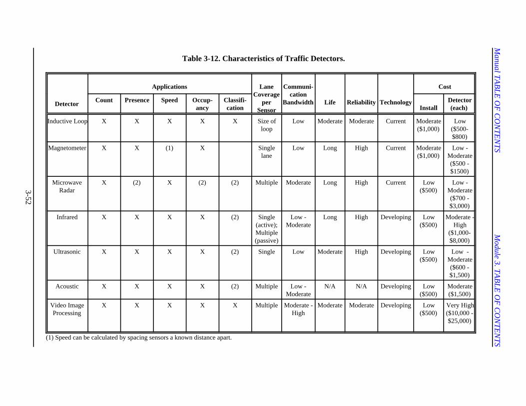
Manual TA
BLE
OF
CO
NTE
NTS
Module 3. TA
BLE
OF
CO
NTE
NTS
3-52
Table 3-12. Characteristics of Traffic Detectors.
Detector
Applications LaneCoverage
perSensor
Communi-cation
Bandwidth Life Reliability Technology
Cost
Count Presence Speed Occup-ancy
Classifi-cation Install
Detector(each)
Inductive Loop X X X X X Size ofloop
Low Moderate Moderate Current Moderate($1,000)
Low($500-$800)
Magnetometer X X (1) X Singlelane
Low Long High Current Moderate($1,000)
Low -Moderate($500 -$1500)
MicrowaveRadar
X (2) X (2) (2) Multiple Moderate Long High Current Low($500)
Low -Moderate($700 -$3,000)
Infrared X X X X (2) Single(active);Multiple(passive)
Low -Moderate
Long High Developing Low($500)
Moderate -High
($1,000-$8,000)
Ultrasonic X X X X (2) Single Low Moderate High Developing Low($500)
Low -Moderate($600 -$1,500)
Acoustic X X X X (2) Multiple Low -Moderate
N/A N/A Developing Low($500)
Moderate($1,500)
Video ImageProcessing
X X X X X Multiple Moderate -High
Moderate Moderate Developing Low($500)
Very High($10,000 -$25,000)
(1) Speed can be calculated by spacing sensors a known distance apart.
Manual TABLE OF CONTENTS Module 3. TABLE OF CONTENTS
3-53
system. Advantages of vehicle probes are or she passes through a toll plaza. Becausethat the following measurements can tolls are collected automatically, the vehicletypically be obtained: can pass through the toll plaza without
C Link speeds.
C Link travel times. of automatically collecting travel time
C Origin and destination of vehicle Texas, AVI systems have been installed totraveling through system. monitor traffic operations on the main lanes
Types of Vehicle Probes
Emerging technologies that utilize vehicles collect current travel time information. Thisas probes include the following: information is used to alert freeway
C Automatic Vehicle Identification (AVI). congestion on both the main lanes and the
C Automatic Vehicle Locating (AVL).
C Cellular Telephone Probes. been in use for several years, uses a radio
Automatic Vehicle Identification (AVI)
AVI systems permit individual vehicles to be the type of source required to power theuniquely identified as they pass through a transponder and the degree to which thedetection area. Although there are several transponder can be programmed.different types of AVI systems, they alloperate using the same general principles. A Classes of transponders, based on type ofroadside communication unit broadcasts an power source, include the following:interrogation signal from its antenna. Whenan AVI-equipped vehicle comes within range C Active.of the antenna, a transponder (or tag) in thevehicle returns that vehicle’s identification C Passive.number to the roadside unit. Theinformation is then transmitted to a central C Semi-Active.computer where it is processed. In mostsystems, the transponder and reader/antennatechnology are independent of the computersystem used to manage and process thevehicle identification information. (3)
Currently, the most common application ofAVI technology is for automaticallycollecting tolls on tollways. In thisapplication, toll charges are electronicallydeducted from the driver’s account when he
stopping.
AVI technology may also be used as a means
information along freeways. In Houston,
and the high-occupancy vehicle (HOV) laneson three major freeways. Vehicles equippedwith transponders are used as probes to
operators to potential incidents and
HOV facilities. (29)
The original AVI technology, which has
frequency signal from the roadside toactivate a transponder located in the vehicle.Transponders can be classified according to
(30)
Active. With active transponders, power tothe transponder is supplied from either aninternal battery or a connection to thevehicle’s power supply. The transponder isactivated by an interrogation signal from theroadside communication unit. It responds tothe signal by broadcasting its own signal(which contains the identification number forthe vehicle) from an internal transmitter.This type of transponder generally has a
Manual TABLE OF CONTENTS Module 3. TABLE OF CONTENTS
3-54
greater operating range and is more reliable facility or by the agency issuing thethan other types of transponders. The life transponder; however, they cannot byexpectancy of an active transponder is reprogrammed without returning thebetween 7 and 10 years. transponder to the manufacturer.
Passive. With passive systems, the Type II. These transponders havetransponder does not require any internal or read/write capability. In these transponders,external power supply. Instead, the some of the memory contains permanentinterrogation signal from the antenna is information (such as vehicle identificationmodulated and reflected to the reader. number) and cannot be reprogrammed.Because the return signal is weaker, passive However, additional memory can besystems typically produce less lane-to-lane provided and may be reprogrammed orinterference than active systems. The weak written remotely from the reader. This typereturn signal, however, causes passive of transponder is typically used in tolltransponder systems to have shorter systems to record time, date, location, andoperating distances. Due to the simplicity of account balance for vehicles.their circuitry, passive transponders have alife expectancy of approximately 40 years.
Semi-Active. Semi-active transponders use extended memory and are capable of fullan operating approach similar to that of two-way communication. With this system,passive transponders in that they are vehicles can be warned of incidents,activated only after an interrogation signal is congestion, or adverse weather conditions,received from the reader. Unlike passive enabling drivers to take alternative routes.transponders, however, semi-active This type of system requires sophisticatedtransponders use an internal power to boost technology for both the roadside andthe return signal to the reader. This vehicle-based equipment.increases the reading distance of thetransponder. Like active transponders, asemi-active transponder has a life expectancyof approximately 7 to 10 years. AVL systems enable the approximate
Classes of transponders, based on the degree tracked as it traverses the transportationto which they can be programmed, include network. These systems have many uses forthe following: many different customers, including the(25)
C Type I.
C Type II. emergency vehicles.
C Type III. C Transit Agencies - track vehicles and
Type I. Type I transponders are read-onlytags that contain fixed data, such as a vehicleidentification number. They can initially beprogrammed either at the manufacturing
Type III. These transponders are alsoknown as “smart cards.” They have
(4)
Automatic Vehicle Location (AVL)
location of a vehicle to be determined and
following:(31)
C Emergency Services - aid in dispatching
provide passengers with arrival timeestimations through information displays.
C Delivery Companies - plan the mostefficient dispatch of fleet vehicles.
Manual TABLE OF CONTENTS Module 3. TABLE OF CONTENTS
3-55
C Private Citizens - allow instant dispatch positional accuracy of dead-reckoning andof tow truck in the event of a vehicle map-matching, most AVL systems use morebreakdown or to recover a stolen advanced technology options.vehicle.
This technology can also be used todetermine the severity of congestion or theoccurrence of an incident, by obtainingprobe reports from vehicles traveling in thenetwork. Software in a control center canautomatically monitor travel speeds andtransit times of vehicles equipped with AVLtechnology.
There are numerous techniques andtechnologies than can be used for locatingthe vehicle, including the following:(31)
C Dead-Reckoning and Map-Matching.
C Signpost.
C Ground-Based Radio Navigation.
C Loran-C.
C Global Positioning Systems (GPS).
C Differential GPS.
Dead-Reckoning and Map-Matching.Dead-reckoning systems monitor thevehicle’s internal compass and odometer andcalculate its position by measuring itsdistance and direction from a known centralstarting point. Dead-reckoning systemsfrequently get off track and can be correctedusing a technique called map-matching.Map-matching systems store a map of thevehicle’s coverage area in a database andassume that when a vehicle changesdirection, it must have turned from one roadon to another. When a vehicle does make aturn, map-matching systems alter thevehicle’s record location to the nearestpossible point at which the turn could havetaken place. Because of the low degree of
Signpost. When vehicles, such as transitbuses, regularly travel a fixed route, manyfleet operators have found that signpost-based positioning systems offer analternative to more advanced AVLtechnologies. Antennas are placed atlocations throughout the vehicle’s route andrecord the time when the vehicle passesnearby. A signpost-based AVL system canalso be a valuable extension of systemsintended for other purposes. Readerantennas that communicate with vehicle tagsfor electronic toll collection can also trackthe location of vehicles from one toll boothto another. The Harris County TollAuthority in Houston and the Illinois TollAuthority in Chicago are currently usingsuch systems.
Ground-Based Radio-Navigation. In“terrestrial” or “ground-based” radio-navigation, the AVL vendor sets up severalreceiving antennas in a metropolitan area.Each appropriately equipped vehiclebroadcasts a radio frequency (RF) signal toall nearby receiving antennas. By measuringthe time it takes for the signal to travel to theantenna, the distance from the vehicle to theantennas can be determined. If the vehicle’ssignal was received by three or moreantennas, the vehicle’s position can beuniquely determined. A disadvantage ofradio-navigation is that RF signals havedifficulty transmitting through largeobstructions, such as mountains, tunnels,parking garages, and metropolitan canyonsformed by the large buildings that line manydowntown city streets.
Ground-based radio-navigation systems areamong the most inexpensive AVL systemsfor the user. However, since constructing
Manual TABLE OF CONTENTS Module 3. TABLE OF CONTENTS
3-56
the necessary infrastructure requires receivers in the same locale, virtuallysignificant financial investment on the part of eliminating all errors in measurements. the AVL vendor, these systems are usuallyavailable only in dense metropolitan areaswith large market potential.
LORAN-C. LORAN-C is similar toground-based radio navigation, except that ituses a communication system set up by theU.S. Government. Uncertainty about thegovernment’s future plans for this systemhave lead to a decrease in the number ofcommercial AVL systems using LORAN-C.In addition, LORAN-C communicationsignals often experience errors due toatmospheric conditions.
Global Positioning System. Globalpositioning systems (GPS) use a network of24 satellites that are continuously orbitingthe Earth to locate any object anywhere onthe planet. The satellites are available free-of-charge to anyone with a device capableof receiving the satellite signals. The U.S.Department of Defense (DOD) launched thesatellites in order to track objects of intereston the ground. The position of the objects isdetermined measuring how long a radiosignal takes to reach the object from multiplesatellites. GPS is by far the most accurateglobal navigation system ever devised, withaccuracies in the range of 5 to 30 meters.Similar to radio-navigation, GPS signalshave difficulty transmitting through largeobjects. The signals also have troubletransmitting through opaque objects, such asleaves on trees.
Differential GPS. Differential GPS is atechnique used to improve the accuracy ofstandard GPS. With differential GPS, areceiver placed at a known locationcalculates the combined error in the satelliterange data. By knowing the error,correction factors can be applied to all other
Cellular Telephones
Using radio frequency receivers andtriangulation techniques, it is possible todetermine a vehicle’s location by measuringsignals resulting from cellular phone usagewithin the vehicle. In conjunction with map-matching algorithms, vehicles (cellularprobes) can be tracked as they traverse areafreeways. The ability to track vehicles viacellular telephones allows vehicle speeds, aswell as travel times for various freewaysegments to be measured. With so manycellular telephones currently in operation,this system has a potential to provide aninexpensive source of traffic surveillance.(31)
A test project was conducted in theWashington, DC, area to test the feasibilityof using cellular probes to obtain real-timetravel information. The surveillance(32)
system was based on passive geolocations(only vehicles that have initiated a call willbe used for the period during which the callis active). This method typically provides asufficient probe population, since cellularphone usage is directly correlated with trafficcongestion.
The cellular surveillance system consists oftwo basic components:
C Geolocation control system (GCS).
C Traffic information center (TIC).
At the GCS, a direction finding system(consisting of a series of towers) is used toprovide latitudes and longitudes of cellularprobes. This information is sent to the TIC,where information on traffic conditions isderived from a series of probes. Trafficinformation is then disseminated to the users(e.g., operators at control center).
Manual TABLE OF CONTENTS Module 3. TABLE OF CONTENTS
3-57
When an initiated call is detected by the C Cellular telephones.GCS, the following information is collectedand sent to the TIC: C Freeway service patrols.
C Time. C Call boxes.
C Probe ID number (randomized to ensure Mobile reports are most often used forprivacy). incident detection. A survey of existing
C Latitude and longitude. United States revealed that a significant
C Information as to whether a key number through service patrols or cellular calls.(such as 911) was called. Frequently, mobile reports help detect
C Information on whether the probe was automatic incident detection.within the boundary of interest.
C Confidence factor associated with theaccuracy of the latitude and longitude. This method of quick detection is becoming
If the message is within bounds, the TIC telephones on the roadways continues touses the position to determine which traffic increase. Some traffic management systemslink the probe is traveling on. If a key have established free cellular call numbersnumber is used, the TIC requests additional for reporting incidents or requesting aid.information from vehicles within a certain These toll free numbers connect the callerdistance of the call. Once it has been directly to the traffic management center orverified that the requested probes are on the to other agencies responsible for respondingtraffic link in question, speeds are calculated. to incidents. Numbers that are easy toThe TIC keeps historical information on remember (such as 999 or CALLMAP)speed profiles for various traffic links by should be used to help these systems betime-of-day. Incoming speeds are compared effective. It is estimated that half of allwith these historical files. If the difference incidents are reported via cellular telephones.between current speed and historical speed Other advantages of this system include theexceeds a set threshold value, a potential following:incident flag is set. Data from additionalprobes is then requested by the GCS. If the C Low start-up costs.threshold value is exceeded a certain numberof times, an incident is posted. C Two-way communication between caller
MOBILE REPORTS
Potential freeway surveillance techniques detection depends on the number of cellularthat should not be overlooked are those telephones on the roadway and theclassified as mobile reports. Examples of willingness of drivers to report incidents. Tomobile report methods include the following: increase effectiveness, a campaign to inform
freeway management systems around the
portion of incidents are detected either(33)
incidents faster than many methods of(34)
Cellular Telephones
more of a resource as the number of cellular
(3)
and response agency.
The effectiveness of this method of incident
drivers about the cellular call-in system and
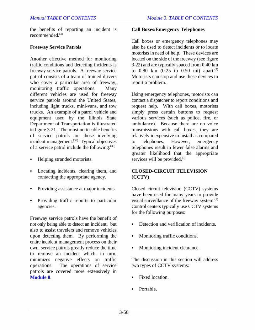
Manual TABLE OF CONTENTS Module 3. TABLE OF CONTENTS
3-58
the benefits of reporting an incident isrecommended.(3)
Freeway Service Patrols
Another effective method for monitoring located on the side of the freeway (see figuretraffic conditions and detecting incidents is 3-22) and are typically spaced from 0.40 kmfreeway service patrols. A freeway service to 0.80 km (0.25 to 0.50 mi) apart.patrol consists of a team of trained drivers Motorists can stop and use these devices towho cover a particular area of freeway, report a problem.monitoring traffic operations. Manydifferent vehicles are used for freeway Using emergency telephones, motorists canservice patrols around the United States, contact a dispatcher to report conditions andincluding light trucks, mini-vans, and tow request help. With call boxes, motoriststrucks. An example of a patrol vehicle and simply press certain buttons to requestequipment used by the Illinois State various services (such as police, fire, orDepartment of Transportation is illustrated ambulance). Because there are no voicein figure 3-21. The most noticeable benefits transmissions with call boxes, they areof service patrols are those involving relatively inexpensive to install as comparedincident management. Typical objectives to telephones. However, emergency(35)
of a service patrol include the following: telephones result in fewer false alarms and(36)
C Helping stranded motorists. services will be provided.
C Locating incidents, clearing them, andcontacting the appropriate agency.
C Providing assistance at major incidents. Closed circuit television (CCTV) systems
C Providing traffic reports to particular visual surveillance of the freeway system.agencies. Control centers typically use CCTV systems
Freeway service patrols have the benefit ofnot only being able to detect an incident, but C Detection and verification of incidents.also to assist travelers and remove vehiclesupon detecting them. By performing the C Monitoring traffic conditions.entire incident management process on theirown, service patrols greatly reduce the time C Monitoring incident clearance.to remove an incident which, in turn,minimizes negative effects on traffic The discussion in this section will addressoperations. The operations of service two types of CCTV systems:patrols are covered more extensively inModule 8.
Call Boxes/Emergency Telephones
Call boxes or emergency telephones mayalso be used to detect incidents or to locatemotorists in need of help. These devices are
(3)
greater likelihood that the appropriate(3)
CLOSED-CIRCUIT TELEVISION(CCTV)
have been used for many years to provide(1)
for the following purposes:
C Fixed location.
C Portable.
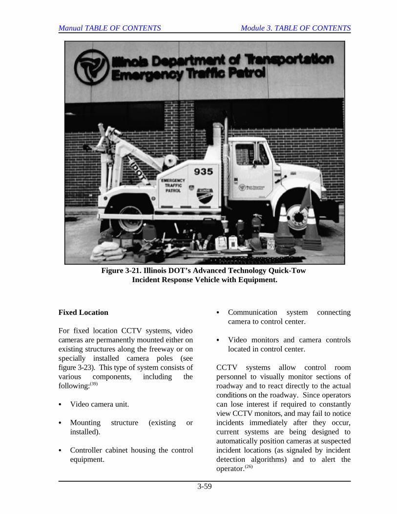
Manual TABLE OF CONTENTS Module 3. TABLE OF CONTENTS
3-59
Figure 3-21. Illinois DOT’s Advanced Technology Quick-Tow Incident Response Vehicle with Equipment.
Fixed Location
For fixed location CCTV systems, videocameras are permanently mounted either on C Video monitors and camera controlsexisting structures along the freeway or on located in control center.specially installed camera poles (seefigure 3-23). This type of system consists of CCTV systems allow control roomvarious components, including the personnel to visually monitor sections offollowing: roadway and to react directly to the actual(39)
C Video camera unit. can lose interest if required to constantly
C Mounting structure (existing or incidents immediately after they occur,installed). current systems are being designed to
C Controller cabinet housing the control incident locations (as signaled by incidentequipment. detection algorithms) and to alert the
C Communication system connectingcamera to control center.
conditions on the roadway. Since operators
view CCTV monitors, and may fail to notice
automatically position cameras at suspected
operator.(26)
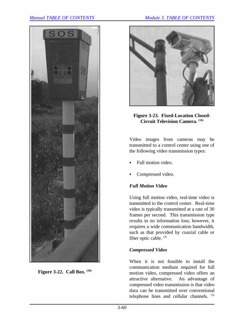
Manual TABLE OF CONTENTS Module 3. TABLE OF CONTENTS
3-60
Figure 3-22. Call Box. (38)
Figure 3-23. Fixed-Location Closed-Circuit Television Camera. (16)
Video images from cameras may betransmitted to a control center using one ofthe following video transmission types:
C Full motion video.
C Compressed video.
Full Motion Video
Using full motion video, real-time video istransmitted to the control center. Real-timevideo is typically transmitted at a rate of 30frames per second. This transmission typeresults in no information loss; however, itrequires a wide communication bandwidth,such as that provided by coaxial cable orfiber optic cable. (3)
Compressed Video
When it is not feasible to install thecommunication medium required for fullmotion video, compressed video offers anattractive alternative. An advantage ofcompressed video transmission is that videodata can be transmitted over conventionaltelephone lines and cellular channels. (3)
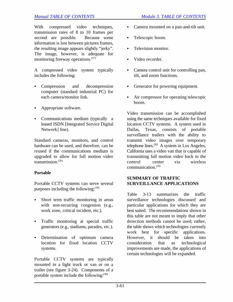
Manual TABLE OF CONTENTS Module 3. TABLE OF CONTENTS
3-61
With compressed video techniques, C Camera mounted on a pan-and-tilt unit.transmission rates of 8 to 10 frames persecond are possible. Because some C Telescopic boom.information is lost between pictures frames,the resulting image appears slightly “jerky”. C Television monitor.The image, however, is adequate formonitoring freeway operations. C Video recorder.(27)
A compressed video system typically C Camera control unit for controlling pan,includes the following: tilt, and zoom functions.
C Compression and decompression C Generator for powering equipment.computer (standard industrial PC) foreach camera/monitor link. C Air compressor for operating telescopic
C Appropriate software.
C Communications medium (typically a using the same techniques available for fixedleased ISDN [Integrated Service Digital location CCTV systems. A system used inNetwork] line). Dallas, Texas, consists of portable
Standard cameras, monitors, and control transmit video images over temporaryhardware can be used, and therefore, can be telephone lines. A system in Los Angeles,reused if the communications medium is California uses a video van that is capable ofupgraded to allow for full motion video transmitting full motion video back to thetransmission. control center via wireless(26)
Portable
Portable CCTV systems can serve severalpurposes including the following:(39)
C Short term traffic monitoring in areas surveillance technologies discussed andwith non-recurring congestion (e.g., particular applications for which they arework zone, critical incident, etc.). best suited. The recommendations shown in
C Traffic monitoring at special traffic detection methods cannot be used; rather,generators (e.g., stadiums, parades, etc.). the table shows which technologies currently
C Determination of optimum camera However, it should be taken intolocation for fixed location CCTV consideration that as technologicalsystems. improvements are made, the applications of
Portable CCTV systems are typicallymounted in a light truck or van or on atrailer (see figure 3-24). Components of aportable system include the following:(40)
boom.
Video transmission can be accomplished
surveillance trailers with the ability to
(26)
communication.(39)
SUMMARY OF TRAFFICSURVEILLANCE APPLICATIONS
Table 3-13 summarizes the traffic
this table are not meant to imply that other
work best for specific applications.
certain technologies will be expanded.
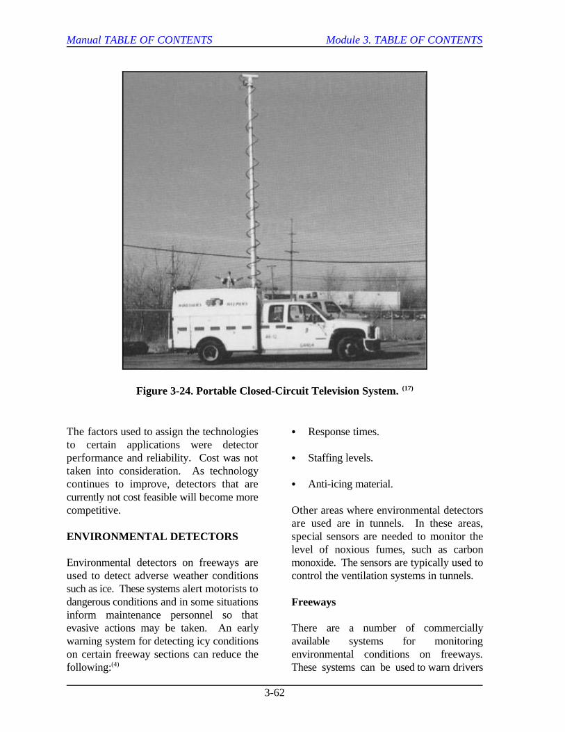
Manual TABLE OF CONTENTS Module 3. TABLE OF CONTENTS
3-62
Figure 3-24. Portable Closed-Circuit Television System. (17)
The factors used to assign the technologies C Response times.to certain applications were detectorperformance and reliability. Cost was not C Staffing levels.taken into consideration. As technologycontinues to improve, detectors that are C Anti-icing material.currently not cost feasible will become morecompetitive. Other areas where environmental detectors
ENVIRONMENTAL DETECTORS
Environmental detectors on freeways are monoxide. The sensors are typically used toused to detect adverse weather conditions control the ventilation systems in tunnels. such as ice. These systems alert motorists todangerous conditions and in some situationsinform maintenance personnel so thatevasive actions may be taken. An early There are a number of commerciallywarning system for detecting icy conditions available systems for monitoringon certain freeway sections can reduce the environmental conditions on freeways.following: These systems can be used to warn drivers(4)
are used are in tunnels. In these areas,special sensors are needed to monitor thelevel of noxious fumes, such as carbon
Freeways
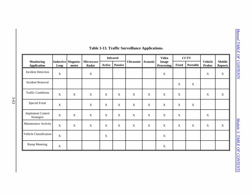
Manual TA
BLE
OF
CO
NTE
NTS
Module 3. TA
BLE
OF
CO
NTE
NTS
3-63
Table 3-13. Traffic Surveillance Applications.
MonitoringApplication
InductiveLoop
Magneto-meter
MicrowaveRadar
InfraredUltrasonic Acoustic
VideoImage
Processing
CCTVVehicleProbes
MobileReportsActive Passive Fixed Portable
Incident DetectionX X X X X
Incident RemovalX X
Traffic ConditionsX X X X X X X X X X X
Special EventX X X X X X X X X
Implement ControlStrategies
X X X X X X X X X X
Maintenance ActivityX X X X X X X X X X X X
Vehicle ClassificationX X X
Ramp MeteringX X
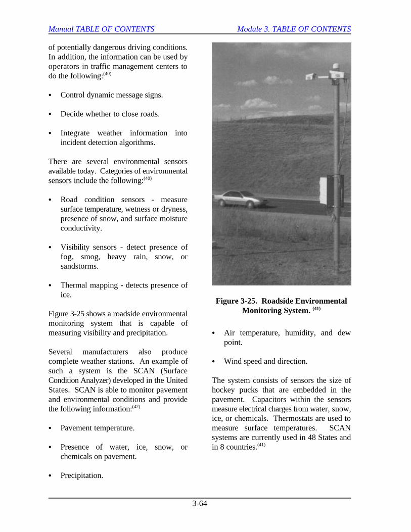
Manual TABLE OF CONTENTS Module 3. TABLE OF CONTENTS
3-64
Figure 3-25. Roadside EnvironmentalMonitoring System. (41)
of potentially dangerous driving conditions.In addition, the information can be used byoperators in traffic management centers todo the following:(40)
C Control dynamic message signs.
C Decide whether to close roads.
C Integrate weather information intoincident detection algorithms.
There are several environmental sensorsavailable today. Categories of environmentalsensors include the following:(40)
C Road condition sensors - measuresurface temperature, wetness or dryness,presence of snow, and surface moistureconductivity.
C Visibility sensors - detect presence offog, smog, heavy rain, snow, orsandstorms.
C Thermal mapping - detects presence ofice.
Figure 3-25 shows a roadside environmentalmonitoring system that is capable ofmeasuring visibility and precipitation. C Air temperature, humidity, and dew
Several manufacturers also producecomplete weather stations. An example of C Wind speed and direction.such a system is the SCAN (SurfaceCondition Analyzer) developed in the United The system consists of sensors the size ofStates. SCAN is able to monitor pavement hockey pucks that are embedded in theand environmental conditions and provide pavement. Capacitors within the sensorsthe following information: measure electrical charges from water, snow,(42)
C Pavement temperature. measure surface temperatures. SCAN
C Presence of water, ice, snow, or in 8 countries.chemicals on pavement.
C Precipitation.
point.
ice, or chemicals. Thermostats are used to
systems are currently used in 48 States and(41)
Manual TABLE OF CONTENTS Module 3. TABLE OF CONTENTS
3-65
Tunnels
Monitoring systems in tunnels are used tolimit the build-up of noxious fumes from The ability of agencies to effectively operatevehicle exhausts. Output from the monitors and maintain a freeway management systemis used to perform the following functions: is vital to the success of the system. This
C Control tunnel ventilation. operations and maintenance of surveillance
C Warn drivers of poor visibility.
C Set safe speed limits within the tunnel.
Most systems monitor the level of noxious the day-to-day function of a system. Thegases and visibility by using infrared primary responsibility of personnel in chargeabsorption techniques. A gas monitoring of operating a surveillance system is tosystem typically consists of the following: monitor freeway conditions. Freeway
C Infrared transmitter and receiver. including the following:
C Electronic signal processing unit. C Monitoring traffic operations.
Outputs from the monitors are sent to the C Detecting incidents.system controlling tunnel ventilation. Tunnelventilation becomes more cost effective C Monitoring incidence clearance.when operated in conjunction with amonitoring system. Cost savings arise from C Monitoring environmental conditions.reduced frequency of operation andmaintenance of the ventilation system. C Supporting the implementation of(43)
There are currently many systems available control strategies.for monitoring air quality within a tunnel;however, it is important that a monitoring Operators may monitor freeway conditionssystem be reliable, accurate, and able to by using any of the following devices:operate with minimal maintenance.(44)
3.4 LESSONS LEARNED
OPERATIONS AND MAINTENANCE
Effective operations and maintenance of atraffic management system are required toensure that the system meets certainobjectives, such as the following:
C Continuously accomplishes the goals andobjectives for which it was designed.
C Responds to changing technologies andtransportation system demands.
(6)
section discusses issues associated with the
systems.
Operations
Operations includes those tasks involved in
monitoring may serve several purposes,
C Displays or printouts showing conditionseither graphically or in a tabular format.
C Closed-circuit television systems.
C Mobile reports.
Additional tasks with which an operator maybe involved include the following:(4, 6)
C Controlling and managing equipment andensuring continuity of operation.
Manual TABLE OF CONTENTS Module 3. TABLE OF CONTENTS
3-66
C Monitoring system performance criteria. C Address maintenance needs (e.g.,
C Updating system databases. costs, personnel requirements) during
C Notifying maintenance personnel ofsystem malfunctions. C Ensure that required budget and staffing
C Communicating with transportation andemergency response agencies. C Perform cost tradeoff analyses during the
C Documenting daily operational functions reducing maintenance requirements.and events such as incident occurrences,equipment failures and repairs, and C Consider that complex surveillancechanges in software and hardware technologies require higher personnelcomponents. skill levels to maintain.
Maintenance
Proper design and installation techniques areimportant to ensure the success of a system. C Keep accurate records of maintenanceMaintenance, however, is also a critical task activities to aid in predicting futurethat must be considered if the system is maintenance needs and in analyzinggoing to operate as intended. Maintenance costs.activities can be grouped into threecategories:(4)
C Remedial. The success of a system begins with the type
C Preventive. Budgetary and funding problems that traffic
C Modification. selection of equipment mainly on the basis of
Remedial maintenance is necessitated by cost. Consequently, less expensivemalfunctions and equipment failures, and equipment is purchased during theusually demands emergency repair to restore installation process. However, this is notoperations. Preventive maintenance includes always the most cost-effective solution. work done at scheduled intervals to Therefore, operations and maintenance costsminimize equipment failure. Modification should be considered together with start-upinvolves replacing equipment and usually costs during the equipment selectionresults from equipment design flaws or process.required upgrades to improve systemperformance. All three maintenance A Texas Department of Transportationcategories should be considered in (TxDOT) research project establisheddetermining budget requirements. guidelines for estimating operations and
For a maintenance program to be successful, were based on the following sources:the following factors should be considered:(4)
maintenance requirements, maintenance
the planning process.
needs can be met.
design phase to identify techniques for
C Ensure that maintenance personnelreceive adequate training.
Operations and Maintenance Costs
and quality of the equipment being utilized.
agencies typically face may result in the
initial start-up cost, rather than on lifetime
(11)
maintenance costs. The cost estimates(6)
Manual TABLE OF CONTENTS Module 3. TABLE OF CONTENTS
3-67
C TxDOT metropolitan districts with through State and local maintenancesubstantial ITS deployment. budgets. These funds are often insufficient
C ITE report, Operation and Maintenance maintenance functions. Therefore, it isof Electronic Traffic Control Systems. important that continued funding for
C FHWA report, Cost Estimates and the planning stage.Assumptions for Core Infrastructure.
C Texas municipalities and transit agencies.
C Technical journals. impact on privacy, because there is no need
C Equipment suppliers. is a critical concern when using technologies
Table 3-14 shows the operations and and cellular telephone tracking. Privacy ismaintenance cost estimates for a surveillance also a concern with the use of closed-circuitsystem. This table lists the estimated unit television.operations cost, estimated unit maintenancecost, combined operations and maintenance A survey of drivers in the United Statescost, and the assumptions related to factors showed that in 1978, 67 percent of peopleincluded in each of the costs. Using were concerned about privacy. Results fromquantities measured in terms of the base 1994 showed that the percentage hadunits shown in the table, total operations and climbed to 84 percent, revealing that privacymaintenance costs can be determined. Note is a major concern for drivers.that the estimated maintenance costs includemaintenance personnel costs, while the Although some people may not mind if theirestimated operations costs do not included vehicles alone are identified, many fear thatpersonnel costs. surveillance from different sources (e.g.,
Most of the operations and maintenance habits, etc.) could be combined to build acosts in table 3-14 are given as ranges in detailed personal profile of their lifestyles.order to allow for adjustments for the The ability to compile information about anfollowing factors: individual’s travel patterns, toll payments,
C Age and quality of equipment. a database that has not previously existed.
C Personnel skill levels. this kind of information is highly
C System designs. inappropriate access to and use of this
In many situations, outside financing sourcesare more readily available for the It must be taken into account that privacy isdevelopment and construction of new one of the goals against which any system’ssystems than for operating and maintaining effectiveness may be measured. Forthe systems once they are built. Operating example, one of the first AVI tolling systemsand maintenance costs are typically funded
because of competition with other
operations and maintenance be addressed in
PRIVACY CONCERNS
Most surveillance technologies have little
for vehicle identification. Privacy, however,
that identify vehicles, such as AVI, AVL,
(45)
credit card purchases, phone calls, travel
and other activities creates the potential for
Due to advances in computer technology,
transportable, and opportunities exist for
personal information.(46)
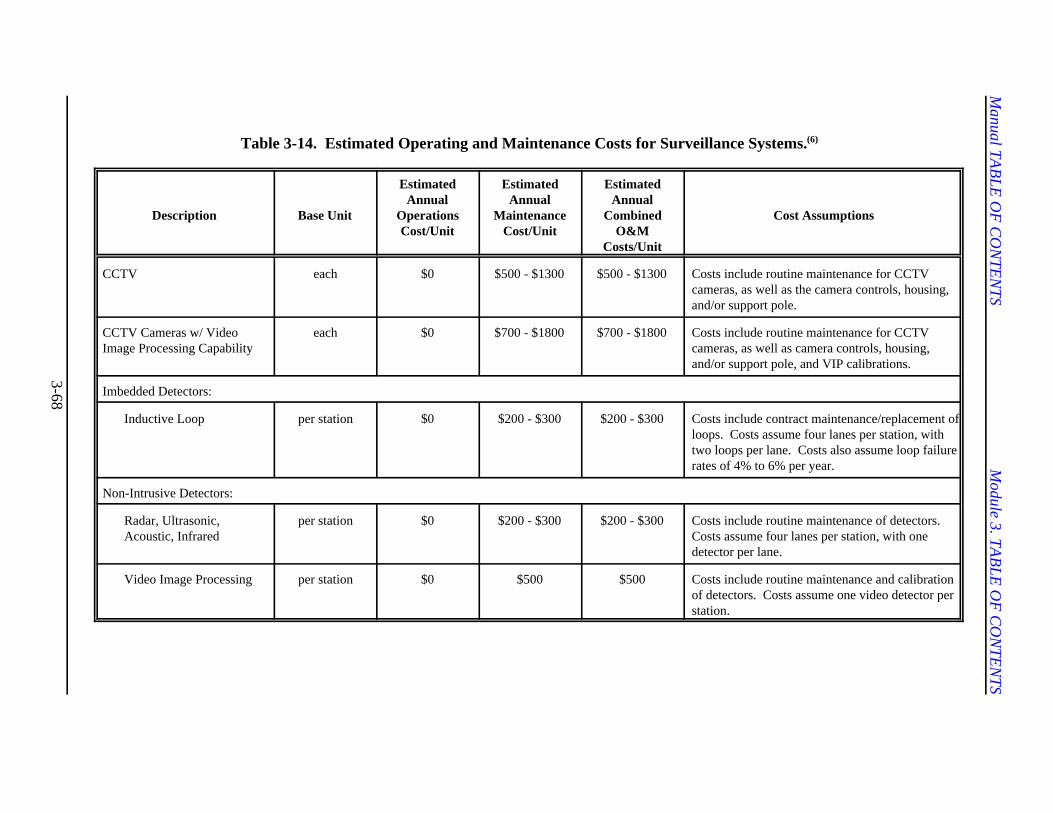
Manual TA
BLE
OF
CO
NTE
NTS
Module 3. TA
BLE
OF
CO
NTE
NTS
3-68
Table 3-14. Estimated Operating and Maintenance Costs for Surveillance Systems.(6)
Description Base Unit
EstimatedAnnual
OperationsCost/Unit
EstimatedAnnual
MaintenanceCost/Unit
EstimatedAnnual
CombinedO&M
Costs/Unit
Cost Assumptions
CCTV each $0 $500 - $1300 $500 - $1300 Costs include routine maintenance for CCTVcameras, as well as the camera controls, housing,and/or support pole.
CCTV Cameras w/ VideoImage Processing Capability
each $0 $700 - $1800 $700 - $1800 Costs include routine maintenance for CCTVcameras, as well as camera controls, housing,and/or support pole, and VIP calibrations.
Imbedded Detectors:
Inductive Loop per station $0 $200 - $300 $200 - $300 Costs include contract maintenance/replacement ofloops. Costs assume four lanes per station, withtwo loops per lane. Costs also assume loop failurerates of 4% to 6% per year.
Non-Intrusive Detectors:
Radar, Ultrasonic,Acoustic, Infrared
per station $0 $200 - $300 $200 - $300 Costs include routine maintenance of detectors. Costs assume four lanes per station, with onedetector per lane.
Video Image Processing per station $0 $500 $500 Costs include routine maintenance and calibrationof detectors. Costs assume one video detector perstation.
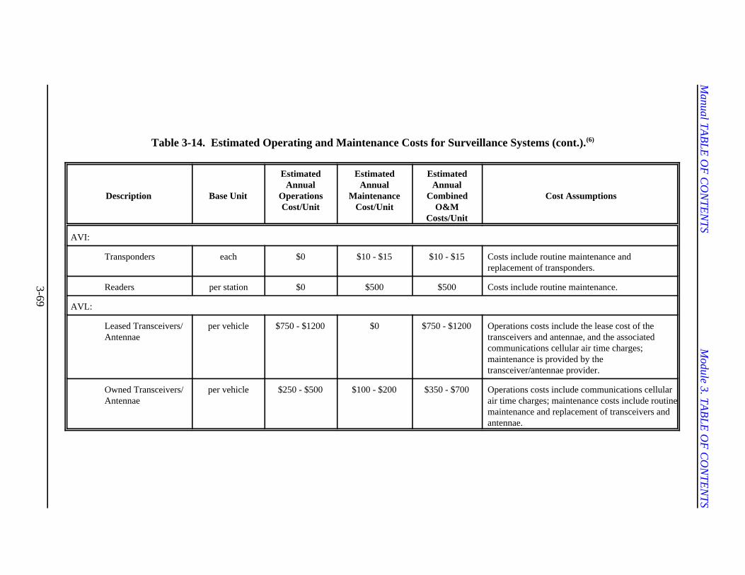
Manual TA
BLE
OF
CO
NTE
NTS
Module 3. TA
BLE
OF
CO
NTE
NTS
3-69
Table 3-14. Estimated Operating and Maintenance Costs for Surveillance Systems (cont.).(6)
Description Base Unit
EstimatedAnnual
OperationsCost/Unit
EstimatedAnnual
MaintenanceCost/Unit
EstimatedAnnual
CombinedO&M
Costs/Unit
Cost Assumptions
AVI:
Transponders each $0 $10 - $15 $10 - $15 Costs include routine maintenance andreplacement of transponders.
Readers per station $0 $500 $500 Costs include routine maintenance.
AVL:
Leased Transceivers/Antennae
per vehicle $750 - $1200 $0 $750 - $1200 Operations costs include the lease cost of thetransceivers and antennae, and the associatedcommunications cellular air time charges;maintenance is provided by thetransceiver/antennae provider.
Owned Transceivers/Antennae
per vehicle $250 - $500 $100 - $200 $350 - $700 Operations costs include communications cellularair time charges; maintenance costs include routinemaintenance and replacement of transceivers andantennae.
Manual TABLE OF CONTENTS Module 3. TABLE OF CONTENTS
3-70
to be implemented was in Hong Kong in and maintenance procedures. The following1983. Each month, drivers using the discussion presents recommendations for theelectronic tolling system were sent spacing and placement of mainline trafficstatements that contained itemized accounts detectors and CCTV cameras.of where they had driven and when. Thedrivers didn’t like the idea of a governmentagency tracking their daily highway travel;therefore, the system was removed twoyears after it was introduced, despite the factthat the technology worked. For reasons For monitoring traffic conditions and(46)
like these, it is very important to design any incident detection, detectors should besurveillance with privacy in mind. placed along the freeway and on ramps to
Fortunately, it is relatively easy to design Guidelines for detector spacings are asmost surveillance systems with privacy in follows:mind. For example, AVI systems can be(45)
designed to assign vehicles a random C Typical mainline detector spacings rangeidentification number for monitoring between 0.40 and 0.80 km (0.25 and 0.5purposes, in which case the identification of mi).the driver is never made. This same processcan be used with AVL and cellular-based C Spacings over 0.8 km (0.5 mi) aretraffic surveillance systems. inadequate for incident detection(32)
In general, consumers may be willing to giveup a certain degree of privacy if they feel C Spacings below 0.4 km (0.25 mi)that the benefits will outweigh the risks (as generally produce little or no increase inin the case of credit card use). It is therefore effectiveness.important that the public be informed aboutthe benefits of using certain surveillance C Tunnels or covered roadway sections aretechnologies. The key to overcoming exceptions, and may require spacings ofprivacy concerns is to inform the public less than 0.4 km (0.25 mi).about what information is being collectedand how the data will be used. C Minimally, at least one traffic detector(47)
SPACING AND PLACEMENT ISSUES
Selecting the location of detectors is an to 1.5 mi).important step in the implementation of asurveillance system. Spacing and placement C Detectors are also typically placedaffect both the cost and performance of the before and after freeway bottleneckssystem. The detectors should be placed (e.g., entrance ramps, lane closures, etc.)close enough together to provide adequate and metered entrance ramps.surveillance of the system, but as the spacingdecreases, the cost of the system increases.In addition, it is desirable to place thedetectors in a location that will result in As discussed earlier, most existing trafficminimum delay to traffic during installation detectors can be classified as either
Mainline Traffic Detectors
Spacing
detect changes in traffic conditions.
(3,4)
purposes.
station should be provided betweeninterchanges or freeway ramps, withmaximum spacings of 1.6 to 2.4 km (1.0
Placement
Manual TABLE OF CONTENTS Module 3. TABLE OF CONTENTS
3-71
embedded or non-intrusive. An embedded C Ongoing maintenance costs may bedetector system consists of sensors in or minimal.below the surface of the roadway. Non-intrusive detectors are mounted on astructure above the surface of the pavement.
The following issues associated with to provide visual monitoring of freewayinstalling and maintaining embedded conditions and to verify incidents. Thedetectors: California Department of Transportation,
C Installation typically requires drilling into CCTV camera site selection. Theor cutting the pavement. following is a summary of these
C Embedded detectors usually have higherinstallation costs than non-intrusivedetectors.
C Installation may require lane closure, have a viewing range of 0.8 km (0.5 mi) inwhich results in delay to vehicles. all directions. Full freeway coverage would
C When feasible, embedded detectors of 1.6 km (1 mi). Full coverage of allshould be installed during the freeways, however, is frequently costconstruction or rehabilitation of a prohibitive. Therefore, proper camera sitefreeway to avoid delays to traffic. selection becomes a critical factor. Factors
C Because modifications to the pavement a camera site include:structure are required for the installation,deterioration of the road surface is C Surveillance of congested freewayescalated; therefore, there are further sections to provide maximum visibilityongoing maintenance costs associated and coverage of weaving and mergingwith replacing damaged detectors or areas near ramps and interchanges.repairing degraded road surfaces.
Non-Intrusive Detectors
Issues associated with installing andmaintaining non-intrusive detectors include C Ability to provide suitable access forthe following: maintenance personnel based on the
C Can typically be installed and maintainedwithout disrupting traffic. C Minimal obstruction to view caused by
C Installation costs are significantly topography.reduced when an existing mountingstructure can be used. C Ability to verify messages of variable
CCTV Cameras
The primary objective of a CCTV system is
District 7, has developed guidelines for(39,48,49)
recommendations.
Site Selection Criteria
Most cameras with a standard 10-to-1 zoom
therefore require a maximum camera spacing
that should be considered in the selection of
C Ability to provide a clear view of areaswith high accident frequencies (based onaccident data).
geometric layout of the area.
landscaping, billboards, freeway signs, or
message signs.
Manual TABLE OF CONTENTS Module 3. TABLE OF CONTENTS
3-72
C Ability to effectively address power, with standard 10-to-1 zoom and a viewingcommunication, and underground utility range of 0.8 km (0.5 mi), video surveillanceconsiderations. can be provided for a 1.6 km (1 mi) freeway
C Ability to provide suitable access to the horizontal or vertical curves).proposed communication system.
Candidate sites for CCTV systems may be process is to perform a field check. Theprioritized on the basis of accident frequency objectives of the field check are to verify the(high, medium, and low). Threshold values following:to classify accident frequencies should bebased on local conditions. Areas with high C Veiling range at “ground eye level.”accident frequencies will require videosurveillance to expedite incident detection C Geometric layout.and clearance. Areas with medium and lowaccident frequencies may also require video C Maintenance access.surveillance. Site selections for theselocations will be based on local criteria, such C Power and utility concerns.as the importance of a particular freewaysection. In addition, video surveillance may While in the field, each preliminary sitebe used to monitor ramps and freeway selected should be marked so that the site issections near heavy traffic generators (e.g., easily identifiable for the final site selectionstadiums) during special events. process.
Preliminary Site Selection Final Site Selection
Preliminary site selection should be based on The purpose of the final task is to perform athe criteria discussed above. These sites video survey to verify camera viewingshould be noted on a scaled base map, along ranges and select correct mounting heights.with the following characteristics of the For high-speed freeway sections, a mobilefreeway: CCTV camera system is recommended.
C Accident frequencies plotted over 0.4 Following are considerations for selectingkm (0.25 mi) intervals. mounting heights:
C Strategic roadway infrastructure. C Mounting heights on poles generally
C Locations of variable message signs.
C Locations of underground high-risk susceptible to vandalism.utility lines.
Cameras should be located in the vicinity of result in maintenance problems andhigh-accident frequency areas and near safety hazards.variable message signs and other strategicareas. Areas with high-risk utility linesshould be avoided if possible. For cameras
section (assuming no blockage due to
The next step in the preliminary site selection
vary from 6.0 to 13.7 m (20 to 45 ft).
C Heights below 6.0 m (20 ft) may be
C Pole heights above 13.7 m (45 ft) may
Manual TABLE OF CONTENTS Module 3. TABLE OF CONTENTS
3-73
C Lower heights (between 6.0 and 9.1 m how to use the software to the City of Miami[20 and 30 ft]) are preferred when it is for 112 days at a nominal cost.necessary to look beneath overpasses. The City of Miami was responsible for
C Cameras at heights below 10.7 m (35 ft) have their vehicles equipped withcan be accessed by a small bucket truck. transponders. Many of the drivers recruited
C Cameras at heights between 10.7 and downtown, and this provided coverage for 513.7 m (35 and 45 ft) would require a of the 17 corridors in the peak directionlarger hoist truck. during the peak period. Installation of the
When possible, cameras should be mounted hour. A single AVL unit consisted of adirectly on existing structures. This will control unit (about the size of a video taperesult in a significant reduction in the initial cassette) and a “pancake” antenna.installation costs.
3.5 EXAMPLES
MIAMI AUTOMATIC VEHICLELOCATION (AVL) (32)
The City of Miami, Florida, needed anaccurate, inexpensive method of collectingaverage travel speed data in order tocalculate roadway level of service asrequired by the 1985 Florida GrowthManagement Act. In 1988, the City ofMiami staff determined that automaticvehicle location (AVL) technology could beused to measure speeds on specificcorridors. (AVL is a means of continuouslymonitoring the location of vehicles in a roadnetwork. Vehicles are equipped with atransponder device that transmits a radio-frequency (RF) signal to a central location atregular intervals.) In 1993, the City ofMiami contracted with the Center for UrbanTransportation Research (CUTR) to set upa field operational test of AVL to measurevehicle operating speeds on 17transportation corridors in the city. CUTRrecruited AirTouch Teletrac to serve as thevendor for the AVL system. AirTouchTeletrac agreed to provide 25 transponders,one workstation, one copy of itsFleetDirector™ software, and training on
recruiting 25 volunteer drivers willing to
commuted from the periphery of the city to
transponders for each vehicle took about one
AirTouch Teletrac provided training on theuse of the software to CUTR researchersand the City of Miami Planning staff andthen provided a workstation, which was aCompaq 386 computer with an internal high-speed modem. The city provided adedicated phone line for communicationbetween the workstation and AirTouchTeletrac’s operations center in FortLauderdale. (AirTouch Teletrac maintains anetwork of 27 receiving antennas throughoutDade, Broward, and Palm Beach counties inSouth Florida. RF signals from the receivingantennas are transmitted to AirTouchTeletrac’s operations center in FortLauderdale.)
The software was configured to poll each ofthe 25 vehicles’ positions every 30 secondswhen the vehicle ignition was on and every5 minutes when the vehicle ignition was off.Each time a vehicle’s position was recorded,the following information was obtained:vehicle number, speed, time, date, andlocation. Data were recorded for thefollowing time periods:
C Weekday mornings, 5 a.m. to 10 a.m.
C Weekday afternoons, 3 p.m. to 8 p.m.
C Saturdays, 10 a.m. to 2 p.m.
Manual TABLE OF CONTENTS Module 3. TABLE OF CONTENTS
3-74
Data were gathered for 112 days, and data with the capability of identifying taggedfor over 4400 vehicle trips were obtained. vehicles at periodic intervals along theCUTR staff wrote two software programs to roadway.analyze vehicle-location data and reportaverage speed. In order to determine the TRANSCOM is an umbrella organizationaccuracy of the calculations for average trip serving the New York/New Jerseyspeeds, CUTR researchers also set up a metropolitan area in coordinating andprocess to compare observed values with disseminating transportation information. Incalculated values for the average speed over 1991, TRANSCOM retained a team led bya vehicle trip. Method 1 yielded a ± 8.3 PB Farradyne, Inc., to establish thepercent accuracy, and Method 2 yielded a ± feasibility of using ETTM equipment for7.1 percent accuracy. Since Method 2 was traffic surveillance and incident detectionmore accurate, it was used in compiling the applications. The project was calledoutput. TRANSMIT (TRANSCOM’s System for
CUTR has demonstrated that the AirTouch divided into two phases. The first phaseTeletrac automatic vehicle location system concentrated on evaluating the use of ETTMcan be used to measure average vehicle technology for traffic surveillance and onoperating speeds on Miami’s 17 developing a preliminary design of a traffictransportation corridors in the peak direction surveillance system for an ETTM incidentduring the peak period, given sufficient detection system. The second phaseelectronic storage capacity, appropriate data included the final design and construction ofanalysis software, and volunteer drivers. the initial stage of the system as an 28.8-kmThis system could be used anywhere in the (18-mi) operational field test along sectionssix metropolitan areas where AirTouch of the New York State Thruway and theTeletrac is available. However, in order to Garden State Parkway. The primaryconduct this experiment outside of those six objective of the TRANSMIT project was toareas, an AVL vendor would have to be process available traffic flow data for earlyenlisted. detection of incidents and abnormal traffic
TRANSCOM ELECTRONIC TOLLAND TRAFFIC MANAGEMENT(ETTM)(50,51)
ETTM, or electronic toll and traffic within five minutes with a false alarm rate ofmanagement, has seen rapid growth. two percent or less. The analysis used theCurrently, more than 20 agencies in 8 following roadway classes: arterial, two-lanecountries have installed a system and are highway, and three- to four-lane highway.collecting tolls automatically. Another 23 The results indicated that the arterialagencies in 7 countries are in the process of roadway class would result in the longesttesting, studying, or implementing automatic detection time. The analysis concluded thattoll collection. ETTM systems have the the five-minute detection time could bepotential to be used for other ITS achieved if the following percentages ofapplications that could include congestion equipped vehicles were provided:pricing, advanced payment systems, travelerinformation, and traffic management. C Two-lane highways: 0.9 percent.ETTM requires the installation of readers
Managing Incidents and Traffic) and was
congestion.
An analysis was conducted to determine thereader antenna spacing and toll tagpenetration necessary to detect an incident
Manual TABLE OF CONTENTS Module 3. TABLE OF CONTENTS
3-75
C Three- and four-lane highways: 2.1 instrument the metropolitan freeway systempercent. in Houston with an automatic vehicle
C Arterials: 7.6 percent. conditions. The AVI system was designed
An 28.8-km (18-mi) corridor along the New 120 miles of freeways and 100 miles ofYork State Thruway in Westchester and reversible high-occupancy vehicle (HOV)Rockland Counties and the Garden State lanes. Parkway in Bergen County were defined foran operational field test. Twenty-two The initial planning began in 1991. TheETTM sites were constructed, and existing North Houston Corridor, with three paralleloverhead sign structures and overpasses radial freeways, was selected as the studywere used for the placement of reader site. This corridor had several favorableantennas. New structures were built where characteristics: one toll facility with availableexisting structures were not available. capacity; one freeway with heavy congestion
The incident detection algorithm developed reconstruction activities; and one freewayby PB Farradyne, Inc., determines the with moderate congestion and an HOV lane.probability of an incident when tagged The corridor also served the Houstonvehicles detected at an upstream reader are Intercontinental Airport, the central businessnot detected at the downstream reader district, and other major activity centers. Awithin the expected arrival time. The later a demonstration project was designed usingvehicle is, the higher the probability of an cellular telephones for the collection ofincident. traffic condition information. This project
At the time this project was designed, the and from work using one of the threetechnology for Electronic Toll Collection freeway routes. The demonstration project(ETC) in the Greater New York/New Jersey was conducted for about 18 months, duringMetropolitan Area was undetermined, so it which time a more permanent and automatedwas decided that the ETTM antennas and system for traffic monitoring was beingreader cabinet equipment would be leased, developed using AVI technology. Thenot purchased. Therefore, if the traffic demonstration project was a success in thatsurveillance concept is found to be valid, useful real-time travel time informationsuccessful and is expanded throughout the was collected and made available to theregion, the equipment can be made public in a variety of ways.compatible with the regional ETC equipmentfrom which the tag population originates.The construction cost estimate for theoperational field test was $1,195,600, whichincluded equipment leasing costs for a 24- The Connecticut Department ofmonth period. Transportation (ConnDOT) chose radar
HOUSTON AUTOMATICVEHICLE IDENTIFICATION (AVI) (52)
The Texas Department of Transportation demonstration project coveringawarded the first of three contracts to approximately 19 km (12 mi) of Interstates
identification (AVI) system to monitor traffic
to provide travel time information on about
because of inadequate capacity and
recruited 200 volunteers who commuted to
CONNECTICUT MICROWAVERADAR (13)
detection for the recent design of theirfreeway surveillance system. Connecticuthas two separate systems operating withinthe State. The first system is a federal
Manual TABLE OF CONTENTS Module 3. TABLE OF CONTENTS
3-76
I-84 and I-91 in the Hartford area, and it is detectors and installation configurations tothe first surveillance system in the country to determine the detector accuracy. Theutilize radar as an incident detection difference between vehicle and detectedtechnology. Because of the early success in speed ranges from 4 km/h (2.5 mi/h) for theHartford, radar detection is also being used narrow beam detector, to 5.6 ki/h (3.5 mi/h)in the design of the I-95 Freeway for the wide beam detector in a side-fireManagement System. The I-95 system is configuration, and up to 10 mi/h for the longinstalled along the southern coast of range detector. The errors associated withConnecticut, covering 90 km (56 mi) from the long range detector can be attributed tothe New York State border east to Branford. the operating principle and placement of theBoth systems rely on speed data being sent detector. The detector operation is based onback from the radar detectors to monitor the Doppler principle: it is most accuratetraffic flow condition and to detect incidents. when it is aimed directly at the traffic flow.
Three different types of radar detectors are Testing and day-to-day operations havebeing used on the projects: wide beam shown that the radar detectors are highlydetectors, narrow beam detectors, and long accurate during varying traffic and weatherrange detectors. The Radar detectors for the conditions. The degree of reliability andHartford Area ATMS (44 individual accuracy demonstrated by the detectors hasdetectors) have been installed for 2 years. allowed ConnDOT engineers to be confidentDuring this time, only one detector has in the data displayed. With the use of thefailed, and the others have survived harsh video cameras that are also part of thewinters with record snowfalls and system, ConnDOT engineers have been ablesignificantly below-average cold to detect and verify incidents that wouldtemperatures. In addition to their reliable otherwise have been unknown to them, andoperation, the radar detectors have proven to initiate a timely response. Lessonsto be easily installed and setup. learned from the Connecticut system have
The detectors have been installed for only a in Maryland, New Jersey, Massachusetts,few years, but the data looks promising. and Georgia.Testing has been performed for the various
been applied in the development of systems
Manual TABLE OF CONTENTS Module 3. TABLE OF CONTENTS
3-77
3.6 REFERENCES 1. Sumner, R. et. al. Freeway Management Handbook, Volume 2: Planning and Design.
Report No. FHWA-SA-88-027. FHWA, U.S. Department of Transportation,Washington, DC, May 1983.
2. Highway Capacity Manual. Special Report No. 209. TRB, National Research Council,Washington, DC, 1994.
3. Texas Department of Transportation, Highway Design Division. Operations andProcedures Manual, Part IV, Interim Metric Version.
4. Gordon, R.L. et. al. Traffic Control Systems Handbook. Report No. FHWA-SA-95-032.FHWA, U.S. Department of Transportation, Washington, DC, February 1996.
5. ITS Architecture, Implementation Strategy. Joint Architecture Team: Loral FederalSystems & Rockwell International, Prepared for the Federal Highway Administration,revised January 1997.
6. Daniels, G., Starr, T., and Stockton, W.R. Guidelines for Funding Operations andMaintenance of ITS/ATMS. Report No. FHWA/TX-97/1494-1F. Texas TransportationInstitute, College Station, TX, 1996.
7. Sumner, R.L., et. al. Freeway Management Handbook, Volume 3: Operations andMaintenance. Report No. FHWA-SA-88-028. FHWA, U.S. Department ofTransportation, Washington, DC, May 1983.
8. Vacca, J.R. Creating Intelligent Traffic Control Centres. Traffic TechnologyInternational. UK and International Press, Autumn 1995.
9. Zhang, H., and Ritchie, S.G. Real-Time Decision-Support System for FreewayManagement and Control. Journal of Computing in Civil Engineering. American Societyof Civil Engineers. Washington, DC, January 1994, pp 35-51.
10. Prosser, N.A., and Ritchie, S.G. Real-Time Knowledge-Based Integration of FreewaySurveillance Data. Transportation Research Record No 1320. TRB, National ResearchCouncil, Washington, DC, 1991, pp 40-46.
11. Traffic Detector Handbook. Second Edition. Institute of Transportation Engineers.Washington, DC, 1991.
12. Peek Traffic, Inc., Automatic Data Recorders (Produce Brochure).
13. Mauritz, M.R., and Decker, H. Radar: Solving the Incident Detection Loophole. TrafficTechnology International, UK and International Press, Autumn 1995.
Manual TABLE OF CONTENTS Module 3. TABLE OF CONTENTS
3-78
14. Steinback, B.G. Loop Substitution for Intersection Control. Traffic TechnologyInternational ‘96. UK and International Press, 1996.
15. Bullimore, E.D., and Hutchinson, P.M. Life Without Loops. Traffic TechnologyInternational ‘96. UK and International Press, 1996.
16. Michalopoulos, P.G., Jacobson, R.D., Anderson, C.A., and Barbaresso, J.C. FieldDeployment of Machine Vision in the Oakland County ATMS/ATIS Project.Proceedings, IVHS America 1994 Annual Meeting, Atlanta, GE, April 1994, pp 335-342.
17. Krogmeier, J.V., and Sharmo, D.E. Overhead and Wireless: An ATMS for the BormanExpressway. Traffic Technology International. UK and International Press. April/May,1996.
18. Klein, L.A., MacCaalden, M.S., and Mills, M. Detection Technology in IVHS.Proceedings, IVHS America 1993 Annual Meeting, Washington, DC, April 1993, pp644-653.
19. Manor, D. Multiple Zone Radar Detection by RTMS. Traffic Technology International‘96. UK and International Press, 1996.
20. Roussel, J.C., Petrucci, J., Lion, D., and Jaouen, R. BEATRICS Radar System forAutomatic Incident Detection. Traffic Technology International ‘96. UK andInternational Press, 1996.
21. EIS Electronic Integrated Systems, Inc. Radar Technology (Produce Brochure).
22. Polk, A.E., Kranig, J.M., and Minge, E.D. Field Test of Non-Intrusive Traffic DetectiveTechnologies. Proceedings, 1996 Annual Meeting of ITS America, Houston, TX, April1996, pp 456-467.
23. Myers, T. Laser Sensors for Traffic Monitoring and Control. Traffic TechnologyInternational ‘96. UK and International Press, 1996.
24. Duckworth, G.L., et. al. A Comparative Study of Traffic Monitoring Sensors.Proceedings, IVHS America 1994 Annual Meeting, Atlanta, GE, April 1994, pp. 283-293.
25. Michalopoulos, P.G. Incident Detection Through Video Image Processing. Applicationsof Advanced Technologies in Transportation Engineering. American Society of CivilEngineers. New York, NY, 1991.
26. Carvell, J.D., Seymour, E.J., Walters, C.H., and Starr, T.R. Dallas Area-Wide IntelligentTransportation Plan. TxDOT Report 591F, Texas Transportation Institute, Dallas, TX,June 1996.
Manual TABLE OF CONTENTS Module 3. TABLE OF CONTENTS
3-79
27. Odetics (Advertisement). Traffic Technology International. UK and International Press,Winter 1995.
28. Sowell, W.H., and LaBatt, J.S. Video Detection Takes a New Track. Traffic TechnologyInternational. UK and International Press, Winter 1995.
29. Levine, S. Houston Regional Area System. Presented at the 73rd Annual Meeting of theTransportation Research Board, National Research Council, Washington, DC, 1994.
30. Fenno, D. Electronic Toll Collection System. Graduate Student Papers on AdvancedSurface Transportation Systems. Texas A&M University, College Station, TX. August1993.
31. Polk, A.E., and Pietrzyk, M.C. The Miami Method: Using Automatic Vehicle Location(AVL) for Measurement of Roadway Level-of-Service. Proceedings, 1995 AnnualMeeting of ITS America, Washington, DC, April 1995, pp 343-402.
32. Sumner, R., Smith, R., Kennedy, J., and Robinson, J. Cellular Based Traffic Surveillance:The Washington, DC Area Operational Test. Proceedings, IVHS America 1994 AnnualMeeting, Atlanta, Georgia, April 1994, pp 794-798.
33. Balke, K., et. al. Freeway Management Systems: A State-of-the-Practice Review. TaskB of Project, Develop a Freeway Management Handbook. FHWA, U.S. Department ofTransportation, Washington, DC, January 1996.
34. Fink, K.L. An Analysis of Incident Management Programs in North America. GraduateStudent Papers on Advanced Surface Transportation Systems. Texas A&M University,College Station, TX, August 1993.
35. Nowlin, R.L. Institutional Concerns Regarding the Implementation of State ManagedService Patrols.” Graduate Student Papers on Advanced Surface Transportation Systems.Texas A&M University, College Station, TX, August 1994.
36. Reiss, R., and Dunn, W. Freeway Incident Management Handbook. FHWA-SA-91-056.FHWA, U.S Department of Transportation, Washington, DC, July 1991.
37. McDermott, J.M., McLean, C.H., and Smith, A.T. Three Decades of Progress: FreewayTraffic Management in Illinois. ITE Journal, Vo 62(3). Institute of TransportationEngineers, Washington, DC, March 1992, pp 27-31.
38. Aselsan (Advertisement). Traffic Technology International ‘96. UK and InternationalPress. 1996.
39. Lee, L.K., Zachariah, M., and Everett, P. CCTV Camera Site Selection: A FieldExperience. Intelligent Transportation: Serving the User Through Deployment.Proceedings of the 1995 Annual Meeting of ITS America. ITS America, Washington, DC,March 1995.
Manual TABLE OF CONTENTS Module 3. TABLE OF CONTENTS
3-80
40. Purdom, N. Whatever the Weather. Traffic Technology International. UK andInternational Press, Autumn 1995.
41. Scientific Technology, Inc. (Advertisement). Technology International. UK andInternational Press, Winter 1995.
42. Hartwell, G. Scanning the Grapevine. AASHTO Quarterly Magazine. AmericanAssociation of State Highways and Transportation Officials, Washington, DC, October1991.
43. Luchian, S.F., and Krechmer, D. Traffic Control on the Boston Central. TrafficTechnology International. UK and International Press, April/May 1996.
44. Dingle, M. Limiting the Build-up of Noxious Fumes. Tunnels and Tunneling. Morgan-Grampian (Construction Press) LTD, London, United Kingdom, October 1992.
45. Wright, T. Eyes on the Road: Privacy and ITS. Traffic Technology International. UK andInternational Press. Autumn 1995.
46. Dingle, J. IVHS and the Law of Privacy. Pacific Rim Transtech ConferenceProceedings, Volume 1. American Society of Civil Engineers, New York, NY, 1993, pp318-325.
47. Costantino, J. Overcoming Institutional Barriers to IVHS. Transportation Quarterly.Eno Foundation for Transportation, Lansdowne, VA, Winter 1994.
48. Guidelines for Camera Placement. IVHS/TOS Design Guidelines No. 94-01, CaliforniaDepartment of Transportation, District 7, Los Angeles, CA, October 1994 (Revised).
49. Guidelines for CCTV Site Surveying. California Department of Transportation, District7, Los Angeles, CA, February 1994.
50. Yermack, L., Gallagher, M., and Marshall, K.R. ETTM - An Early ITS Winner. ITEJournal, Vol. 65(12), Institute of Transportation Engineers, Washington, DC, December1994, pp 42-48.
51. Marshall, K.R.l and Batz, T. The TRANSCOM TRANSMIT Project: An AlternativeApproach for Traffic Surveillance and Incident Detection. Moving Toward Deployment,Proceedings of the IVHS America 1994 Annual Meeting, ITS America, Washington, DC,1994, pp 555-563.
52. Levine, S.Z., and McCasland, W.R. Monitoring Freeway Traffic Conditions withAutomatic Vehicle Identification Systems, ITE Journal, Vol. 64(3). Institute ofTransportation Engineers, Washington, DC, March 1994, pp 23-28.