Module 234-11 STARTUP AND LOADING Library/20042411.pdf · APPROVAL ISSUE Module 234-11 Course 234 -...
49
APPROVAL ISSUE Module 234-11 Course 234 - Turbine and Auxiliaries - Module 11 N01ES & REFERENCES STARTUP AND LOADING OBJECTIVES: After completing this module you will be able to: 11.1 Explain the reason(s) why: a) The condensate system must be placed in service before the boil- er feed system may be started (2); b) At least one CEP must be running before the gland sealing steam system may be started (I); c) At least one CEP must be in service before the LP turbine ex- baust cooling system may be started (I); d) The boiler feed system must be placed in service before the boil- ers and steam piping can be heated to their normal temperature (I); ¢=>Page 5 ¢=>Page 5 ¢=>Page 5 ¢=>Page 5 e) Wanning of the steam piping should, in principle, be completed ¢=>Page 6 before steam is admined to the turbine (2); t) Boilerptess"", must be sufficiently high (above approximately I ¢=>Page 6 MPa(g» before high condenser vacuum can be acbieved (2); g) The turbine supervisory system is started prior to the other tur- ¢=>Page 7 bine auxiliary systems (I); h) The turbine lube oil system must be in service before the turning ¢=>Page 7 gear can be started (I); i) The gland sealing steam system must not be placed in service ¢=>Page 8 when the turbine generator rotor is stationary (I); j) The low condenser vacuum trip in the ntl'bine governing system ¢=>Page 8 may bave to be gagged prior to steam admission to the turbine (I); k) Turbine steam valves are tested prior to turbine runup (I); ¢=>Page 9 I) At least one CCW pump should be running befote the gland ¢=>Page 10 sealing steam system is started (I); m) Requitements for condenser vacuum become more and more ¢=>Page 11 stringent with in=asing turbine speed (2); n) The LP turbine exhaust cooling system should be placed in ser- ¢=> Pages 11-12 vice before turbine runup is advanced (I). Page 1
-
Upload
truongxuyen -
Category
Documents
-
view
471 -
download
58
Transcript of Module 234-11 STARTUP AND LOADING Library/20042411.pdf · APPROVAL ISSUE Module 234-11 Course 234 -...

APPROVAL ISSUE
Module 234-11
Course 234 - Turbine and Auxiliaries - Module 11
N01ES & REFERENCES
STARTUP AND LOADING
OBJECTIVES:After completing this module you will be able to:
11.1 Explain the reason(s) why:
a) The condensate system must be placed in service before the boiler feed system may be started (2);
b) At least one CEP must be running before the gland sealing steamsystem may be started (I);
c) At least one CEP must be in service before the LP turbine exbaust cooling system may be started (I);
d) The boiler feed system must be placed in service before the boilers and steam piping can be heated to their normal temperature(I);
¢=>Page 5
¢=>Page 5
¢=>Page 5
¢=>Page 5
e) Wanning of the steam piping should, in principle, be completed ¢=>Page 6before steam is admined to the turbine (2);
t) Boilerptess"", must be sufficiently high (above approximately I ¢=>Page 6MPa(g» before high condenser vacuum can be acbieved (2);
g) The turbine supervisory system is started prior to the other tur- ¢=>Page 7bine auxiliary systems (I);
h) The turbine lube oil system must be in service before the turning ¢=>Page 7gear can be started (I);
i) The gland sealing steam system must not be placed in service ¢=>Page 8when the turbine generator rotor is stationary (I);
j) The low condenser vacuum trip in the ntl'bine governing system ¢=>Page 8may bave to be gagged prior to steam admission to the turbine (I);
k) Turbine steam valves are tested prior to turbine runup (I); ¢=>Page 9
I) At least one CCW pump should be running befote the gland ¢=>Page 10sealing steam system is started (I);
m) Requitements for condenser vacuum become more and more ¢=>Page 11stringent with in=asing turbine speed (2);
n) The LP turbine exhaust cooling system should be placed in ser- ¢=> Pages 11-12vice before turbine runup is advanced (I).
Page 1

Course 234 _ Turbine and Auxiliaries - Module 11 APPROVAL ISSUE
Pages 29·30~ 11.5 a)
Pages 30·32~ b)
Page33~ c)
Pages 33·34~ d)
Page34~ e)
Page35~ f)
Pages 35·36~ g)
NOTES & REFERENCES
Page15~
Pages 15·19~
Page19~
Pages 19·20~
Pages 21·23~
Pages 24·26~
Page27~
Page28~
Page 2
11.2 List six major operational concerns which affect the startup andloading of a turbine generator.
11.3 a) Describe two ways in which thermal stresses are created insteam turbines.
b) Explain the reason why thermal stresses become particularlylarge during turbine startups, power manoeuvres, and load rejections.
c) Explain four other Operational causes of large thermal stresses.
d) Desctibe four adverse consequences/operating concerns causedby excessive thermal stresses.
e) Desctibe four general operating practices used to prevent excessive therma1 stresses during turbine startup and loading.
11.4 a) Explain how the brittleness of the turbine generator at low temperatures affects cold startups.
b) For each of the following:
i) Turbine rotor;ii) Generator rotor,
desctibe two methods of prewatming that can be used to increase its temperature enough to prevent brittle failure.
Explain what is meant by axia1 differential expansion (ADE).
Explain three reasons why ADEoccurs in steatn turbines.
Explain the reason why ADE becomes particulatly large duringturbine startups, power manoeuvres, and load rejections.
Explain four other operational causes of abnonna1 ADE.
Desctibe three adverse consequences/operating concerns causedby excessive ADE.
Describe four general operating practices used to prevent excessive ADE during turbine startup and loading.
Describe four major actions performed in response to excessiveADE.
• • •
APPROVAL ISSUE Course 234 - Turbine and Auxiliaries - Module 11
INSTRUCTIONAL TEXT'
INTRODUCTIONOperational experience with large turbine generators shows that once theunit is ronning in a steady power condition, there is relatively little chancefor a major equipment malfunction or failure. However, during startup orshutdown, abrupt load changes or unit upsets, the conditions imposed onthe unit are much more severe, reducing the equipment life and increasingthe risk of failure. In older to minimize these undesirable effects during turbine generator startup and loading, it is important that you understand theoperating practices that are used. While details are left for the station 1lpeCific ttaining, this module covers the following topics:
- Major actions occurring during startup and loading of the steam andfeedwater cycle systems*;
- Major operational concems affecting the turbine generator startup andloading, including:
- Thermal stresses;- Brittleness at low temperatmes;- Axial differential expansion.
Due to numerous station specific differences. the information presented inthis module is very general. This is particularly true with respect to the firsttopic listed above. As for the second topic, you have probably noticed thatits scope is limited only to the turbine generator. This stems from the factthat the major operational problems concerning the boiler, steam system,condenser, feedheating system and their auxiliaries have already been covered in the previous modules.
MAJOR ACTIVITIES DURING STARTUP ANDLOADING OF THE STEAM AND FEEDWATERCYCLE SYSTEMSThe intent of this section is to achieve two goals:
I. To give you a general overview of the major activities performed duringstartup and loading of the steam and feedwater cycle systems.
This overview is only for orientation pwposes (no exam question onthis matter will be asked).
2. To explain why most of these activities must be performed in a certainsequence in order to avoid serious operstional problems.
Yau mav be tested on this material_
NOlES & REFERENCES
... Recall that these systemsinclude the boUer, steamsystem, turbine, condenser, feedheating system and their auxiliaries.
Page 3

Course 234 - Turbine and Auxiliaries - Module 11 APPROVAL ISSUE
NOTES & REFERENCES
.. Note that the reactor, thegenerator and their auxU·iazy systems are not in·eluded.
Page 4
You will find tha~ to a large extent, the infonnation presented in this sectionis a synthesis of the previous modules where individual systems were discussed. one at a time.
A pullout diagram (Fig. 11.6) at the module end depicts the major activitiesperfonned during startup and loading of the steam and feedwater cycle systems·. Vou are advised to unfold this diagram and keep it in sight for reference, while studying this section. To help you locate individual activities inthis diagram, their start and end points are specified in the correspondingdescription below. The points are numbered in the typical order of theirocctl1Tence during aunit startup.
It is assumed in Fig. 11.6 that:
- The initial unit state is an extended shutdown with all major systems inthe shutdown state. Note that in the case of a short outage, many ofthese systems may remain in service (eg. the turbine generator may stillbe on turning gear).
- The following auxiliary systems are already in service, providing thepower and coolant necessary for operation of the remaining systems:
All classes of electrical power;- The LP and HP service water systems;- All compressed air systems.
Initially, startup activities are perfonned on a few parallel paths to save time:
Activities 1-4-5-9 which establish the boiler feedwater flow and preparethe steam system for supplies of steam to the turbine and other equip-ment (eg. reheaters); .
- Activities 1-2-3-6 which place the turbine generator on turning gear inpreparation for runup;
Activities 3-7-9 which prepare turbine steam valves for steam admissionto the turbine;
- Activity 1-6 which places the eew system in service;
- Activities 6-8-11 which produce condenser vacuum required for turbineoperation.
After the above activities have beeri completed, most of the remaining activities are perfonned sequentially. More specifically, activities 9-11-12-13-14result in turbine generator nmup. followed by synchronization with thegrid, and finally loading. The only exception is activity 10-11 which placesthe LP turbine exhaust cooling system in service. This activity can be donein parallel with the initial phase of turbine runup, as shown in Fig. 11.6.
In the text thor follows, each activity is described in more detail.
APPROVAL ISSUE Course 234 _ Turbine and Auxiliaries - Module 11
Placing the condensate system in service (activity 1-4)
The condensate system must be placed in service prior to the boiler feedsystem in order to:
- Ensure adequate supplies of condensate to the suction of the BFPs suchthat the boiler feedwater flow can be sustained;
- Provide injection of cool condensate to the BFP glands, th=by ptevent-ing pump damage.
The condensate flow must also be available before the gland sealingsteam and LP turbine exhaust cooling systems can be placed in service. The reasons are:
- Cooling of the gland exhaust condenser must be established before anygland leak-off steam enters this condenser. You will recall that this ptevents overheating of the gland exhaust fans, steam egress from the turbine and steam valve glands, and formation of steam pockets in thegland exhaust condenser tubes. The latter can lead to steam hammer inthe condensate system as explained in module 234-6.
- The condensate is used as a cooling medium in the LP turbine exhaustcooling system.
The following major steps are performed while placing the condensate system in service. First, the inventory of makeup water is checked and ade·quate supplies are secured. The feedwater chemical treatment system isplaced in service. The whole condensate system, including the DA storagetank, is vented and filled, using the auxiliary CEP.
Once the DA storage tank level is high enough, the electric immersion heaters in the tank are switched on to ptewann the condensate in the tank. Lateron, when boiler wanning (activity 5-9) is advanced enough, boiler steam(typically referred to as startup steam) becomes available for DA heatingand the electric heaters are switched off. Meanwhile, one main CEP is started, upon which the auxiliary CEP is shut down and placed in the standbymode. Additional CEPs are started during unit loading, io meet the increasing DA demand for condensate.
Placing the boiler reed system in service (activity 4-5)
This activity must be completed, before the boilers can be used as a longtenD heat sink for the lIT system. Since boiler steam is required for steampipeline wanning, the boilers - and hence, the boiler feed system - must bein service before the wanning (activity 5-9) can begin. The"'fo"', placingthe boiler feed system in service is a P"'tequisite for activity 5-9.
To place the boiler feed system in service, the piping and the boilers arevented and filled, using the auxiliary BFP. If required for accelerated ptewanning of the DA storage tank condensate, 1-2 main BFPs can be started"
NOlES. REFERENCES
~ Obi. 11.1 a)
~ Obi. 11.1 b)
~ Obi. 11.1 c)
~ Obi. 11.1 d)
... Recall from module 234-6that BFP operation in therecin:ulation mode is notrecommended.
Page 5

Course 234 - Turbine and Auxiliaries - Module 11 APPROVAL ISSUE
NOTES & REFERENCES
Obj. 11.1 e)~
.. These problema have beenexplained in module 234-3.
Obj. 11.1 f) ~
.. Usually, at lent I MPa(g).
.. Again, at least 1 MPa(g).
Page 6
once the tank is filled up. Otherwise, the main BFPs are started lster. as required by the increasing boiler demand on feedw.ter. Once the fIrst mainBFP is started, the .uxiliary BFP is placed in the standby mode.
Warming up the boilers and steam pipelines (activity 5-9)
In principle, this activity must be completed before steam is admitted toIhe turbine in order to prevent
- Excessive thennal stresses in the steam system;- Water hammer in the steam system and w.terinduetion to the turbine'.
In most stations, it is possible - though not recommended -to begin turbinenmup when boiler pressure is slightly below its nOlDlOi value.
Wanning of the boilers must also be significantly advanced, though notnecessarily fInished, 10 enable pulling condenser vacuum (activity 8-11)to • level required for turbine operation. There are two reasons for this dependence:
- The required high condenser vacuum cannot be achieved without sealingthe turbine and steam valve glands. This is performed by the gland sealing steam system which is supplied with boiler steam. For the systemto be able to sdjust the sealing steam pressure properly, the boiler steampressure must be sufficiently high';
In many stations. the vacuum pumps in the condenser air extraction system are of steam jet air ejector type. For proper operation, they heedboiler steam at sufficient pressure*.
Recall that wanning of the boilers and steam pipelines is associated withgradual wanning of the he.t transport (HT) system. During this process,the reactor and lIT pumps supply hest, most of which is allowed to remainin the lIT system, boilers and steam pipelines, thereby raising their temperature. The hesmp rate is controlled by rejecting the surplus he.t in boilersteam to atmosphere or - in the stations with CSDVs - to the main condenser (ifoperative). Note th.t wanning of the steam pipelines includes nOl onlythe main steam piping to the turbine. but also the reheat system piping. theCSDV steam piping, the DA startup and poison prevent hesting steam piping, etc.
Naturally. steam contact with the relatively cool pipework results in intensive condensation of the steam. It is. therefore, very important thatIhe drain valves slay open. Failure to do this may result in accumul.tionof water in the lowest points of the pipelines. leading to water hammer inthe steam system and water induction to the turbine when the fIrSt steam isadmitted.

APPROVAL ISSUE Course 234 _ Turbine and Auxiliaries - Module 11
SUMMARY OF THE KEY CONCEPTSo The condensate system must be placed in service prior to the boiler feed
'system for two reasons. First, condensate must be supplied to the suction of the BFPs in order to sustain boiler feedwater flow. Second, coolcondensate must be injected to the g1&nds of the BFPs in order to prevent pump <!&mage.
o The condensate system must be in service before the g\&nd sealing steamsystem is started. Otherwise. lack of cooling Of the g\&ad exh&ust condenser C&n result in overhe&ting of this condenser &ad the g\&nd exhaustf&OS. Steam hammer in the condensate system could also occur.
•. Because the LP turbine exhaust cooling system uses condensate as acooling medium, it cannot operate without the condensate system in service.
o The boiler feed systern mustbe in service before the boilers C&n be usedas a reactor heat sink, &ad hence, before the boilers &ad steam pipingC&n be warmed up to their normal temperature.
o Steam pipelines must be properly warmed &nd drained before steam isadmined to the turbine in order to prevent excessive thermal sttesses &adwater hammer in the piping. as well as water induetim to the turbine.
o Boiler pressure must be sufficiently high to enable pulling condenservacuum to a level at which turbine runup C&n begin. This is because theg\&nd sealing steam system &ad the steam jet air ejectors ~uire boilersteam at sufficient pressure for their proper operation.
Placing the turbine supervisory system in service (activity1-2)
Since the turbine supervisory system provides essential data about the operating state of the turbine generator and its auxiliaries, it is placed in ser"vice before other turhine generator auxiliary systems are started.Note that the system sensors also provide input to Dee software: the Turbine Run-Up (TRU) prognun &nd Unit Power Regulator (UPR) which areused in most stations for automatic turbine startup.
Placing the turbine lUbricating oil system in service (activity2-4)
The turhine lubricating oil system must be running hefore the turninggear can he started. The pwpose is to estahlish adequate lubrication ofthe turbine generator besrings &nd the nuning gear itself. Recall that to proteet this equipment from <!&mage. the control circuit of the nuning gear motor has interlocks preventing its operation when the lube &nd jacking oilpressures are too low.
NOlES & REFERENCES
<=> Obj. Il.I g)
<=> Obj. 11.1 h)
Page 7
Coune 234 - Turbine and Auxiliaries - Module 11 APPROVAL ISSUE
N01ES & REFERENCES
Obi. 11.1 i)~
Obi. 11.1 i) ~
Page 8
In the units where the turbine lube oil is also used as a hydraulic fluid in theturbine governing system, the turbine lubricating oil system must be startedfirst. This is why in Fig. 11.6, this activity is shown as a prerequisite forplacing the tuIbine governing system in service (activity 3-7).
If not already ronning, the purifier and the vapour extraction fans are started. Because the purifier circuit includes a heater, it can be used for prewanning when oil is too cool to be supplied to the turbine generator hearings.
Nex~ cooling water to the lube oil coolers is valved in, and a lube oil pump(usually, the auxiliary oil pump) is started. Finally, the jacking oil pumpsare placed in service.
Placing the turbine on turning gear (activity 3-6)
Recall from module 234-9 that during startup, the turbine is put on turninggear for two purposes:
- To straighten the rotor before runup hegins;- To enable prewanning of the turbine without causing bogging.
In the case of a startup following an extended shutdown, the turbine mayhave to remain on turning gear for up to 24 hours.
Note that this activity is one of the prerequisites for placing the glandsealing steam system in service (activity 6-8). Otherwise, applying botsealing stesm to the stationary turbine would quickly result in its hoggingdue to thenna! stratification of the steam/air abnOSphere inside the machine.This would delay runup until the bogging is rolled out.
Placing the turbine governing system in service (activity3-7)
This activity must be completed before turbine steam valves can betested (activity 7-9).
Part of the system startup is to make sure the hydraulic fluid for valve actuation is available. In most stations, this is provided by starting up the FRFsystem (recall that in a few units, the turbine lubricating oil is used instead).
When the hydraulic fluid is available, the rest of the governing system isplaced in service. The no-load speed and load limiter selpOints are properlyadjusted, and the tripping mechanism tested. In some stations, the lowcondenser vacuum trip is temporarily disabled (or gagged as it is commonly referred to) to prevent it from interfering with the rest of the system.The advantage of doing this is that turbine runup can hegin earlier, ie. without having to wait for full condenser vacuum. Later on during runup, thegagging is removed.

APPROVAL ISSUE Course 234 - Turbine and Auxiliaries - Module 11
Prerunup checks of turbine steam valves (activity 7-9)
When the turbine governing system is operational, the turbine steam valvescan be tested. This is perfonned prior to turbine runup In order to detectvalve malfunction before steam is admitted to tbe turbine. The purpose or this precaution is to minimize chances for operational problems (eg.speed control) and possible equipment damage due to valve failure duringturbine runup and loading. or course, if during these tests any valve isfound in poor condition, turbine startup is delayed until the valve is repaired.
During the valve checks, the turbine isolating valves are closed to preventsteam flow through the turbine. Once the tests are complete, the valves areopened to allow prewamting of the steam piping running to the closed emergency stop valves.
SUMMARY OF THE KEY CONCEPTS.• The turbine supervisory system is placed in service before other turbine
auxiliary systems are started because it provides essential data about theoperational conditions of the turbine generator and its auxiliaries.
• The lube oil system must be placed in service before the turning gear canbe started. Otherwise, interlocks in the turning gear motor circuit wouldnot allow for its startup. This prevents damage to the turbine generatorbearings and the turning gear itself due to lack of adequate lubrication.
• The turbine must be put on turning gear before gland sealing steam isapplied. Otherwise, turbine hogging would result due to thermal stratification of the steam/air atmosphere inside the machine. Turbine runupwould have to be delayed until the hogging is removed.
• The turbine governing system must be in service in order to allow forprerunup testing of turbine steam valves.
• The low condenser vacuum trip may have to be gagged prior to steamadmission to the turbine to allow turbine runup to begin before full condenser vacuum is pulled. This expedites getting the unit on line.
• Turbine steam valves are tested. prior to steam admission to the turbinein order to detect valve malfunction before the turbine is run up. Thisminimizes the risk of operational problems and possible equipment damage due to valve failure during turbine runup or loading.
NOTES & REFERENCES
<=> Obj. 11.1 k)
Page 9
Course 234 _ Turbine and Auxiliaries - Module 11 APPROVAL ISSUE
NOTES & REFERENCES
Obj. 11.1 I) ~
• A few hours.
• This has mady been described in module 234-5.
• This is reflected in Flg.11.6 where activity 6-8is shown as a p:erequisite for activity 8-11.
• Note that during nonnaloperation, the glandsteam leakoff does notcollect there because thelarge turbine steam flowjust sweeps it away.
* Axial differential expansion is defined on pages29-30.
Page 10
Placing the CCW system in service (activity 1-6)
Placing the CCW system in service establishes cooling of the main condenser before any thermal load is imposed. Note that without this cooling andgiven enough time, hot steam leaking into the condenser (eg. from the turbine gland seals) could raise its pressure and temperature enough to causedamage. For example, excessive pressure may rupture a bursting disc in aLP turbine exhaust cover. Though it would .take a long time' before theleaking gland steam could cause such damage, a prudent precaution is tohave at least one CCW pump running before the gland sealing steamsystem is started.
To place the CCW system in service, the vacuum priming system (if installed) and one CCW pump are staned. Gradually, gases are evacuatedfrom the CCW system piping, condenser water boxes and tubes, resultingin their priming with cooling water. Thus, a syphon action is established. inthe CCW system. The remaining CCW pumps are then started. Their startup procedures must be closely followed to avoid water hammer in the system·.
Placing the gland sealing steam system in service (activity6-8).
Operation of the gland sealing steam system is closely associated with pulling condenser vacuum (activity 8·11). Two different approaches areused in different stations, depending on the turbine manufacturer's operational experience.
In some stations, the gland sealing steam system is placed in service beforepulling condenser vacuum begins'. The advantage is that air is not suckedinto the torbine through the unsealed glands when the vacuum is beingpulled. Not only does it facilitate pulling vacuum, but it also prevents contamination of the glands, and ultimately boiler feedwater, with dirt and possibly oil from the adjacent bearings.
In the other stations, placing the gland sealing steam system in service is delayed until partial condenser vacuum has been drawn. This reduces the period of time during which hot gland sealing steam is applied to the turbinewhile condenser vacuum is very poor or zero. Note that due to the effect ofpressure on saturation temp:rature, such poor vacuum increases steam temperature inside the torbine exhaust in the direct vicinity of the glands. Thisis where the gland steam leakoff tends to collect when there is no steamflow through the turbine'. As the leakoff replaces air, the steam partialpressure approaches the turbine exhaust pressure. If this pressure is relatively high (ie. poor condenser vacuum), so is the corresponding saturationtemperature. Through locali2ied heating of this part of the turbine, this hotsteam can cause excessive axial differential expansion"'. This can be avoided by pulling satisfactory condenser vacuum before valving in- the glandsealing steam.

APPROVAL ISSUE Course 234 - Turbine and Auxiliaries - Module 11
Pulling condenser vacuum (activity 8-11)
Pulling condenser vacuum should begin prior to turbine runup such thatcondenser pressure is reduced to a satisfactory level" before turbine speed isincreased. Then, pulling condenser vacuum and turbine runup are continued together.
With rising turbine speed, the requirements for condenser vacuumbecome more and more stringent. For example, while turbine runupmay begin at a condenser pressure not exceeding 50 kPa(a), the pressuremust be reduced to at least IS kPa(a) at 800-1000 rpm, and 8 kPa(a) at1500-1600 rpm".
There are two reasons for i,ncreasing the vacuum requirements with risingturbine speed:
I. To reduce the tendency of the LP turbine exhaust to overheat
2. To prevent excessive flow-induced vibration" of the moving blades inthe turbine last stage(s).
Recall from module 234-1 that both these operational problems are causedby drastic deterioration of the flow pattern in the last stages when the steammoves slower than the turbine blades.
To prevent excessive deterioration of the flow pattern. the steam velocitymust increase when the blade velocity increases with rising turbine speed.Recall that for the steam. velocity to increase, the pressure ratio in the laststages must increase as well. This happens when condenser vacuum israised. The higher the condenser vacuum during turbine nmup, the betterthe flow pattern in the last stages.
Condenser vacuum is pulled by the vacuum pumps in the condenser air extraction system. They evacuate air from the condenser shell, LP and HPturbines and associared steam pipelines (incl. extraction steam piping) UP tothe closed governor valves. To expedite this process, all available vacuumpumps are used.
Placing the LP turbine exhaust cooling system in service(activity 10-11)
The LP turbine exhaust cooling system should be placed in service (ie.ready to supply water to the cooling sprays when turbine exhaust temperature is high enough) before turbine nmup is advanced. This ensures that thesystem is available when needed to protect the LP turbine exhaust fromoverheating. Recall that with rising turbine speed, more frictional heat isprQ<iuced in the turbine last stages when the blades chum the steam fasterand faster. This heat may raise the turbine exhaust temperature to a level requiring system operation, particularly if the nmup is slow or turbine loadingdeferred.
NOlES & REFERENCES
• At leut. below SO kPa(a),
~ Obj. 11.1 m)
... These numbers are quotedjust to illUlltrate thepoint. You do not haveto memorize them. Thevacuum requirmlents usedin your station may differ slightly.
• Blade vibration is covered in the last module.
~ Obj. 11.1 n)
Page 11

Course 234 - Turbine and Auxiliuies - Module 11 APPROVAL ISSUE
N01ES & REFERENCES
Pages 37·39 ~
* In most stations, this isthe turbine runup prognm (fRU).
Page 12
In practice, the system is usually placed in service before turbine runup begins so that the operator can concentrate on monitoring the runup closely.
SUMMARY OF THE KEY CONCEPTS• At least one CCW pump should be running before the gland sealing
steam syslem is started. This prevents the gland leak-off steam fromraising condenser pressure and 1emperature excessively.
• In some stations, the gland sealing steam syslem must be in service before pulling condenser vacuum begins. This prevents dirt, and possiblybesting oil, from being sucked into the turbine through the unsealed·glands. In the other stations, the gland sealing Sleam sySlem is placed inservice only after partial condenser vacuum has been drawn. By sbortening the time during which hot gland sealing steam is applied, turbineaxial differential expansion is minimized.
• Turbine runup should not begin until proper condenser vacuum hasbeen reached. The vacuum requirements grow with rising turbine speedin order to minimize blade vibration in the turbine last stage(s) and the1endency for overheating of the LP turbine exhausL
• The LP turbine exhaust cooling syS1em should be placed in service before turbine ronup is advanced to ensure the syS1em availability to proleet the LP turbine exhaust from overheating. System operation may berequired later on during the ronup when large quantities of frictional heatate produced in the last s!ages due to their blades churning the Sleam athigh velocity.
You may now answer assignment questions 1·10.
Turbine runup (activity 9-11-12)
Before turbine ronup begins, careful checks are performed to make surethe turbine generator and other systems are teady. Some of these checks include the HP turbine rotor eccentricity, condenser vacuum, lube oil pressureand temperature, position of the drain valves in the steam piping, just toname a few.
When the results are satisfactory, the runup can begin. The turbine steamflow is controlled by the turbine governing system whose no-load speedse!pOint is adjus1ed either by the operator or, most often, by the appropriateDCC software'. In both cases, Ihe largel speed and runup rale mustbe determined. This is done either by the operator or by the DCC, depending on the station and the type ofronup control (manual versus automatic).
In some stations, ronup is performed in a few SlepS, and for each of them,its own target speed is specified. Of coune, all target speeds must be outside the turbine generator critical speed ranges in order to plevent excessive
APPROVAL ISSUE Course 234 _ Turbine and Auxiliaries - Module 11
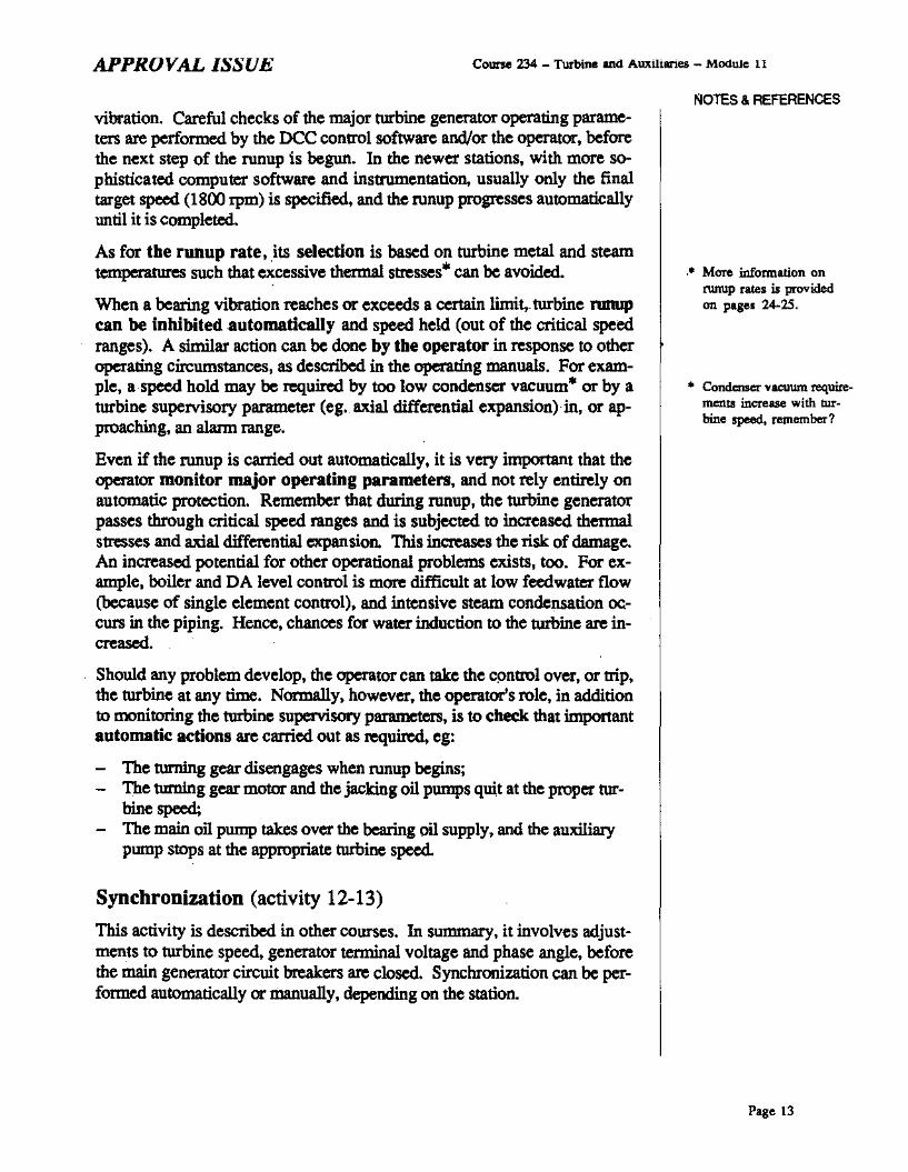
vibration. Careful checks of the major turbine generator operating parameters are performed by the DeC control software and/or the operator, beforethe next step of the runup is begun. In the newer stations, with more so-phisticated computer software and instrumentation, usually only the finaltarget speed (1800 rpm) is specified, and the runup progresses automaticallyuntil it is completed.
As for the runup rate, its selection is based on turbine metal and steamtemperatures such that excessive thetmaI s~sses· can be avoided.
When a bearing vibration reaches or exceeds a certain limit, turbine nmupcan be inhihited automatically and speed held (out of the critical speedranges). A similar action can be done hy the operator in response to otheroperating circumstances, as descnbed in the operating manuals. For example, a speed hold may be required by too low condenser vacuum· or by aturbine supervisory parameter (eg. axial differential expansion) in, or approacbing, an alarm range.
Even if the runup is carried out automatically. it is very important that theoperator monitor major operating parameters, and not rely entirely onautomatic protection. Remember that during runup, the turbine generatorpasses through critical speed ranges and is subjected to increased thermals_ses and axial differential expansion. This increases the risk of damage.An increased potential for other operational problems exists, too. For example, boiler and DA level control is more difficult at low feedwater flow(because of single element control), and intensive steam condensation oc.curs in the piping. Hence. chances for water induction to the turbine are increased.
Should any problem develop, the operator can take the control over, or trip,the turbine at any time. Normally. however, the operator's role, in additionto monitoring the turbine supervisory parameters, is to check that importantautomatic actions are carried out as requimd. eg:
- The turning gear disengages when runup begins;- The turning gear motor and the jacking oil pomps quit at the proper tur-
bine speed;- The main oil pump takes over the bearing oil supply, and the auxiliary
pump stops at the appropriate turbine speed.
Synchronization (activity 12-13)
This activity is described in other courses. In summary, it involves adjustments to turbine speed, generator terminal voltage and phase angle, beforethe main generator circuit breakers are closed. Synchronization can be perfornted automatically or manually, depending on the station.
NOTES & REFERENCES
,. More infonnation onnmup rates is providedon pages 24-25.
... Condenser vacuum requirements increase with turbine speed, remember?
Page 13

Course 234 - Turbine and Auxiliaries - Module 11 APPROVAL ISSUE
N01ES • REFERENCES
• Thennal stresses and theselection of the loadingrate are discussed in moredetail later in this module.
... Recall that in some stations, this is a manualaction.
Page 14
Loading (activity 12-13)
To load the turbine, the operator specifies tbe target generator MWload. The appropriate loading rate is selected either by the operator or,more typically, by the appropriate nec software. The selection is basedmainly on the mrbine metal and steam temperatures to avoid excessive thermal stresses". After that, onit loading progresses at the selected rate until thetarget load is reached.
To effect turbine loading, the no-load speed setpoint to the governing systemis gradually raised, causing the turbine steam flow to increase accordingly.The setpoint can be controlled by the operator. Normally, however, it iscontrolled by the appropriate DCC software. In. most stations, this softwareis UPR (when the unit operates in the reactor lagging mode), and BPC (forthe reactor leading mode). At any time, loading can he inhibited - and inthe extreme case, the turbine nipped - ifa problem arises.
Even when the loading is performed automatically, it is important that theoperator monitors closely all major para1neters as the potential forequipment damage during this large operarional transient is greatly increasedas compared with steady power operation. The operator must also makesure that the major automatic actions are performed at the proper turbineload as specified in the operating manuals. Some of these actions are:
- Various groups of steam pipeline drain valves close at different turbineloads;
- Boiler level setpoint is gradually ramped up;- Boiler and DA level control switches to the large control valves;- Moisture separator drains are directed to the appIopIiate feedheaters rather
than dumped to the condenser; .- "Auto" CEPs and BFPs stan up;- Reheaters are gradually loaded and fully in service at a certain turbine
load";DA heating switches from boiler steam to turbine extraction steam.
Based on the information presented in the preceding modules, you should beable to recall the reasons why these actions are performed.
You have probably noticed that the above description of turbine runup andloading brings together many facts already covered in the preceding modules. The purpose is to help you get an overall picture of these activities.This will hopefully facilitste stodying of the next section.

APPROVAL ISSUE Course 234 - Turbine and Auxiliaries - Module 11
MAJOR OPERATIONAL CONCERNS WHICHAFFECT THE STARTUP AND LOADING OF ATURBINE GENERATORThis section covers tine potential operational problems which can damagethe turbine generator if it is started or loaded improperly. These problemsare:
- Thermal stresses;- Brittleness at low temperature;- Axial differential expansion.
For each of these problems, you willieam about its causes, potential consequences to the turbine generator and the general operating practices used tominimize or prevent it.
Three other important operational concerns are:
- Water induction to the turbine;- Rotor vibration;- Blade stresses.
Partially addressed in the previous section", they are covered in more detailin modules 234-13 and 234-14.
THERMAL STRESSES
In this subsection, you will learn the following:
- How thermal stresses are created;- What adverse consequences and operating concerns they cause, and- What general operating practices are used during turbine startup and
loading to prevent excessive thermal stresses.
Causes
Though thenna1 stresses were mentioned. several times in previous modules,no explanation was given about how they are created. Instead. referenceswere made to this module. And hence, the description that follows applies,in principle, to all equipment.
Thennal stresses can be defined as stresses that are induced in a componentwhen its thermal expansion or contraction is restrained. This can becaused by:
- External constraints, ie. other equipment or other parts of the samemachine, or
- Uneven temperature distribution within the same component suchthat its hotter and cooler parts attempt to expand (or contract) differently.
NOTES & REFERENCES
¢'> Obj. 11.2
.. Recall that steam pipingmust be properly drained(to prevent water induction). 8Ild the condenservacuum requirements in·crease with turbine speed(to minimize bladestresses).
¢'> Obj. 11.3 a)
Page 15
Course 234 - Turbine and Auxiliaries - Module 11 APPROVAL ISSUE
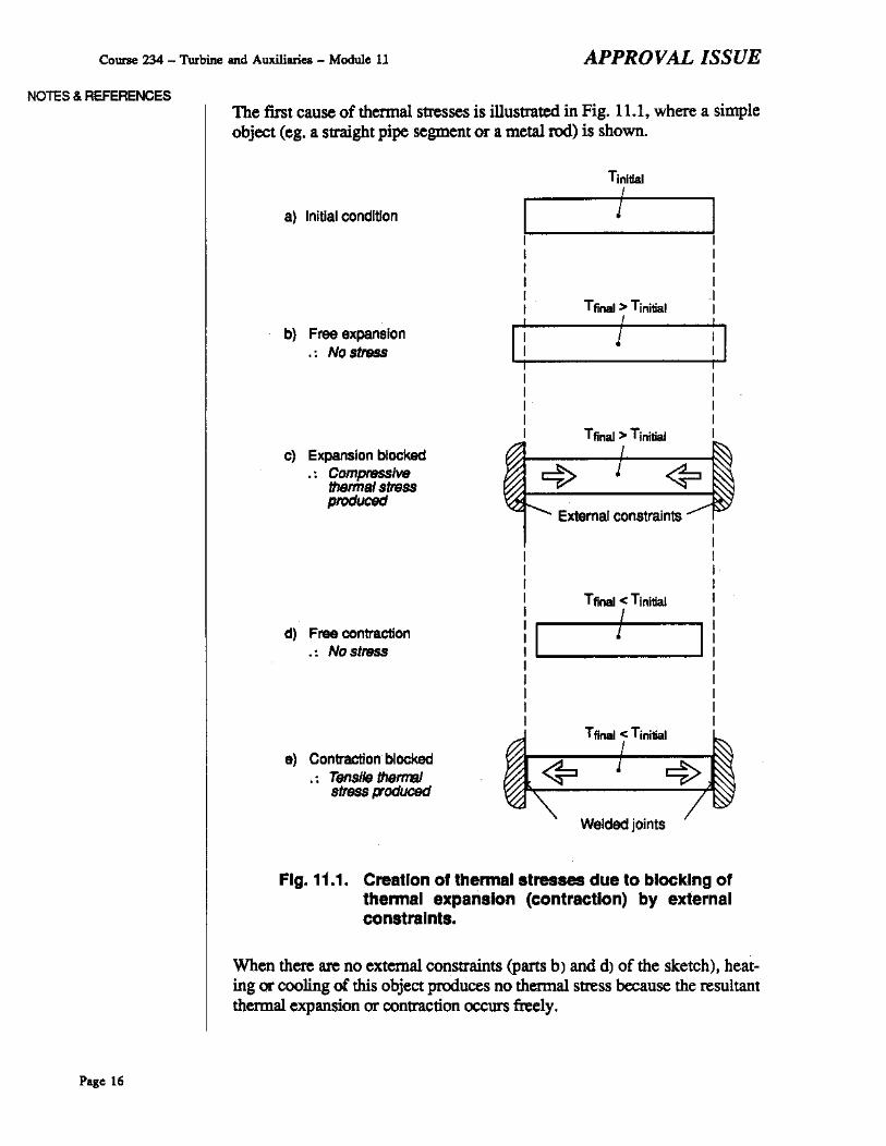
NOTES & REFERENCESThe first cause of thermal stresses is illustrated in Fig. 11.1, where a simpleobject (eg. a straight pipe segment or a metal rod) is shown.
TinitlalI
a) Initial condItion
b) Free expansion.: No stress
Tfrnal > TinitialI
Tfinal > Tinitial
? <?External constraints
II
I II II II Tfinal < Tinitial II ( I
: II I!
I II II II II I
Tfinal < Tinitial
<?Welded joints
0) Contraction t>ocked.. TensllethemBI
stressl7od~
d) Free contraction.: Nostress
c) Expansion blocked.. Compress/WI
thsrmal stressprocJ~
Fig. 11.1. Creation 01 Ihermal slresses due 10 blocking 01Ihennal expansion (conl,acllon) by exte,nalconslralnls.
When there "'" no external constraints (parts b) and d) of the sketch), heating or cooling of this object produces no thermal stress because the resultantthermal expansion or contraction occurs freely.
Page 16

APPROVAL ISSUE Course 234 - Turbine and Auxiliaries _ Module 11
This is not the case in parts c) and e) of the same drawing where the externalconstraints force the object to retain its initial· length. Ifyou compare partsb) and c) of the sketeh, you will see that the external constraints force theobject to be shorter than in the case of free expansion. A conclusion can bedrawn that blocking of thermal expansion produces compressive thennalstresses. Likewise, comparison of parts d) and e) of the same sketch makesit obvious that tensile stresses are created when thennal contraction is con~
strained.
It must be emphasized that blocking of thermal expansion or contraction of one comP9nent by others is potentially very dangerous. It doesnot take a large ternperature change to produce damaging thermal stresses.Therefore, we strive to di.sign and operate equipment in such a way that thiscause of thennal stresses is avoided.
For example, thermal expansion joints (usually, bellows) and loops arecommonly used in piping to sccommodate its thermal expansion/contractionat a ssfe stress level. In the turbine generator, there is only one thrust bearing to allow the rotor to expand/contract freely in the sxial direction. Likewise, turbine casings are supported in such a way that only one end is fixedin the axial direction, whereas the other end Can slide in guides. Similarguides are used to accommodate casing expansion/contraction in the radialdirection as well as to sUPP9rl diaphragms inside the casing. In operation,care must be taken to ensure that the external guides (which are accessibleduring turbine operation) are well greased and that no foreign object isjammed in. Otherwise, the casing expansion/contraction will be blocked,resulting in buckling of the casing (leading to rubbing and incressed vihration) and/or P9ssible damage to its suPP9rlS.
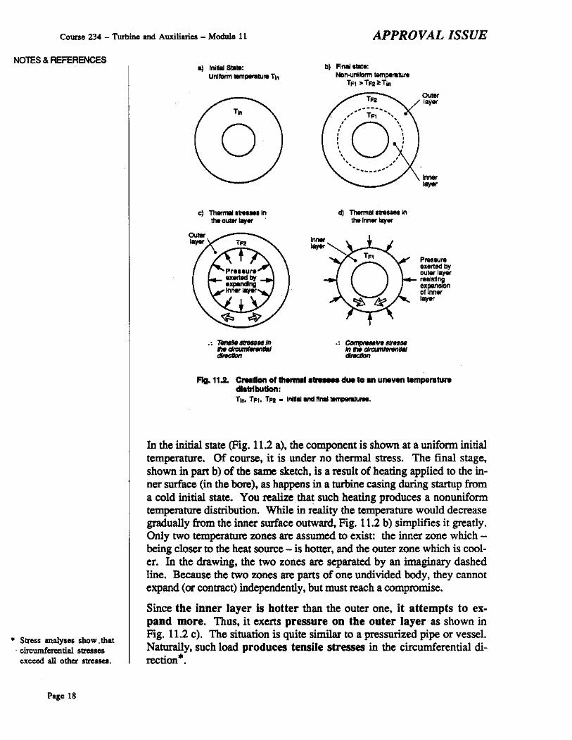
Fig. 11.2 on the next page illustrates the second cause of thermal stresses.A thick-wall cylinder or busbing is used here as an example to show how anuneven temperature distribution within one component (external constraints are absent) creates thermal stresses. You will notice some resemblance of this simple object to a thick turbine casing or a hollow rotor.
NOTES & REFERENCES
• For simplicity, the con·straints are assumed infinitely rigid. In reality,they would yield somewhat under stress, thereby reducing thermalstresses in the component placed in between.
Page 17
Course 234 - Turbine and Auxiliaries - Module 11 APPROVAL ISSUE
NOTES & REFERENCES.) Inllllll S":
Uniform lelTIp....u,u. Tinb) FlI18II '1lIle:
Non-unllann t8mperatuteTFl >Tf2:tTin
c:) ThIlm1lll ,treuN Inthe outer llIy«
PAl,sure....... byaulet layet"....",expansionallnn.'-
T"
.""-d) ThermailtleUe, In
the Innet lily.
....----/0'T" "'", ., ,, ,, ,, ,, ,,. ,. ,, ,, ,~- ....
~-_ .. "
--
o
.: 7ftiIe""'MIn...-FIg. 11.2. CreaOon of thermll ........ due to an uneven temperatu...
dlsb1butlon:TIIIo TFlo Tf2 • InlllallIIIdllna1~.
'" Stress analyses show. that. circumferential stresses
exceed all other stresses.
In the initial state (Fig. 11.2 a), the component is shown at a unifonn initialtemperature. Of course, it is under no thermal stress. The final stage.shown in part b) of the same sketch, is a result of heating applied to the in·ner surface (in the bore), as happens in a turbine casing during startup froma cold initial state. You realize. tha~ such heating produces a nonuniformtemperature distribution. While in reality the temperature would decreasegradually from the inner surface outward, Fig. 11.2 b) simplifies it greatly.Only two temperature zones are assumed to exist: the inner zone which being closer to the heat source - is hotter, and the outer zone which is cooler. In the drawing, the two zones are separated by an imaginary dashedline. Because the two zones are pans of one undivided body, they cannotexpand (or contract) independently, but must reach a comprontise.
Since tbe inner layer is botter than the outer one. it attempts to expand more. Thus. it exerts pressure on tbe outer layer as shown inFig. 11.2 c). The situation is quite sinti1ar to a pressurized pipe or vessel.Naturally, such load produces tensile stresses in the circumferential direction"'.
Page 18

APPROVAL ISSUE Course 234 - Turbine and Auxiliaries - Module 11
Due to its lower temperature, the outer layer attempts to expand less. Itsopposition to the expansion of the inner layer exerts inward pressure(Fig. 11.2 dr on the latter, producing compressive .tresse. in the circumferential direction.
In practice, the temperatuIe di.tribution in any equipment that i. much hotteror cooler than its .urroundings is always nonuniform. Consequently, somethermal s~sses alway. exist, except for prolonged outages when the ternpenlture stabilizes at the ambient level. Usually, thermal .tr..... arefairly low·when the equipment is well insulated and opemted at a .teadyload. This is because under such operating' conditions•. only relativelysmall local tempentture differences (often called temperature gradients) exist within the equipment
However, when equipment is being started up or shut down, or when itsload is being changed, thermal stresses increase significantly. Let us nowconsider a large steam turbine. During runup, loading, unloading or loadrejection, large temperature gradients are set up in tbe !urbine.This is caused by transient heating or cooling due to changes in the steamternpenlture and flow·.
Here is how it happens. When the steam temperature changes, the tern·perature of the part. of the turbine casing and rotor which are in contact with the .team follows quickly. Then the tempenlture of the moreremote parts changes. This involves transfer of large amounts of heat to orfrom the metal. The process gradually proceeds towards the moat remoteparts whose temperature lags behind most. The larger the turbine, the
oslower the process, because larger amounts of heat are involved. In thelargest turbines, it may take a few hours before the most remote parts ofthe casing and rotor reach their normal opemting tempemture. Meanwhile,large tempentture gradients are created.
Large thermal .tresse. can al.o be caused by ahnormal operatingcondition. and accidents. Listed below are four examples:
1. Water induction to the turhine.
If the water is much cooler than the turbine, damaging therma1 stressescan be produced due to severe localiud quenching of the hot turbinemetal. For example, tltis happens when feedwater enters the turbine viaextraction steam piping due to a feedheater tube rupture.
2. Malfunction or failure of the reheaters, LP turhine exhaustcooling system. etc.
Poor performance of this equipment may produce large temperature gradients - and hence, therma1 stresses - in some turbine parts. For example, reheater failure could result in an excessive side-ro-side tempentturedifference at the LP turbine inlet, subjecting the casing to large thermalstresses. .
NOTES & REFERENCES
¢'> Obj 11.3 b)
III Compm-ed with unloading or load rejection,turbine trip' and shutdowns produce smallerthermal stresses becauseturbine cooling.is sloweru there is no steam flowthrough the turbine.
¢'> Obj 11.3 c)
Page 19

Course 234 - Turbine and Auxiliaries - Module 11 APPROVAL ISSUE
NOTES & REFERENCES!fthe LP turbine exhaust cooling system failed (eg. some nozzlesplugged), the LP turbine exhaust could experience excessive heating,leading to in=ased temperatute gradients and thermal stresses.
Another example can be failure of the gland sealing steam system tomaintain the tequited gland sealing steam pressure. Recall from module234-1 that this may upset the flow of air and steam in one or moreglands. As a result, some gland segments may be quenched by the leaking air or rapidly heated by the leaking steam. Large temperature gradients and thenna! stresses would resulL
3. Casing support feetlkeys seized in their guides.
Recall from the description of the casing suppan system (page 17) thatinadequate greasing or a foreign object can block a turbine casing suppan fOOL Very large stresses in the casiog and its support can result.
4. Wet tbermal insulation.
This can cause in=ased temjierature gradients - and hence, thenna!stresses - in the turbine casing. Normally, when the insulation is dry,its thermal resistance is much larger than that of the casing. Consequently, the temperature drop across the insulation is several times larger than across the casing walL As a result, the casing outer surface isonly slightly cooler than the inner one.
However, wetting of the insulation makes it a much better heat conductor. As the beat losses from the casing through the insulation in=ase,the casing outer surface temperature drops. This leads to larger temperature gradients in the casing. The induced thenna! stresses in=ase accordingly.
SUMMARY OF THE KEY CONCEPTS
• Startup and loading of a turbine generator is affected by the followingoperational concerns:
Thenna! stresses;Brittleness at low temperatures;Axial differential expansion;Water induction to the turbine;Rotor vibration;Blade stresses.
• Thenna! stresses are caused by blocking of the thenna! expansion orcontraction of one component by external constraints. The other causeis an uneven temperature distribution within a component, causing itsbotter and cooler parts to a!temp! to expandIcontraet differently.
Page 20

APPROVAL ISSUE Course 234 - Turbine and Auxiliaries - Module 11
• During turbine startups, power manoeuvres and load rejections. thermalstresses can become particularly large. These operating conditions pr0
duce large temperature gradients in the turbine because they result inlarge changes in the steam temperature and flow.
" Large thermal stresses can also be caused by certain abnonnal operatingconditions and accidents such as water induction, seized casing supportfeet or wet thermal insulation. Faulty or malfunctioning equipment(such as reheaters, the LP turbine exhaust cooling system or the glandsealing steam system).can also produce excessive thermal stresses insome turbine parts.
Adverse consequences and operating concerns caused bythermal stresses
Excessive thermal stresses, combined with mechanical stresses· I cause thefollowing adverse consequences/operating concerns, listed in the order ofdecreasing stress magnitude:
1. The stressed component can break instantaneously.
This case is very uncommon because it takes a drastic increase in the total stress magnitude to exceed the ultimate tensile strength'. In practice,other failure mechanisms, such as fatigue or stress corrosion cracking,are more common.
2. The stressed part can deform plastically (permanendy).
For this to happen, the total stress must exceed the yield point (alsocailed elastic limit)". The resultant defOtmation of the casing, a diaphragm or another stationary component, may cause: .
- Rubbing in the turbine due to loss of clearances;
- Increased vibration due to robbing and/or bearing misaligmnent-the laner applying to the case whete bearing pedestals support theturbine casing, and therefore are subjected to large forces produceddue to casing deformation;
- A steam leak through the open half joint (if any).
Plastic deformation of the rotor due to excessive thermal stress is veryrare. The classic case is permanent hogging of the stationary rotor but,as mentioned in module 234-9, it is very unlikely in CANDU stationsdue to the relatively low temperature of boiler steam. Severe robbing isa more likely soutee of thermal stresses that could cause the rotor to buwpermanendy.
3. The stressed part can experience excessive elastic deformation.
Note that some deformation always OCCutS because whenever there is astress, there is also an associated strain. A problem may arise when the
NOTES & REFERENCES
<=> Obj 11.3 d)
• For example, ccnlrifugalstresses in the rotor. andstresses in the cuingdue to steam pressure.
• Recall &om the 228course that the ultimatetensile strength is themaximum tensile stressthat a given material canwithstand before fracture.
• This term, as deftned inthe 228 course, meansthe maximum stress thatcauses no plastic deformation.
Page 21

Course 234 - Turbine and Auxiliaries - Module 11 APPROVAL ISSUE
N01ES & REFERENCESdeformation is too large. This can happen when the total stress. whilestaying below the yield poin~ increases too much. In the case of stationary components, the effects "'" similar 10, though less dramaticthan those outlined in point 2 above.
Though the rotor spinning motion tends 10 equalize its temperature distribution. minor nonunifonnities can still occur dwing fast heating orcooling. The primary reasons "'" that the rotor material is not perfectlyuniform (hence, minor local differences in its thenna1 conductivity), andthe oxides or deposits on its smace can cause slightly uneven rates oflocal best transfer from the steam 10 the rotor smace or vice versa.
Small as they""" rotor defonnations can produce high vibration andpossible rubblng, whes turbine speed is sufficiently high or in a criticalspeed range. Note that these problems do not occur when rotor heatingis sufficiently slow because there is enough time for heat transfer 10equalize the temperature distribution.
4. The stressed components may suffer low cycle tbermal fatigue damage.
The term low cycle thermalfatigue damIlge refers 10 the fatigue damage caused by thermal stresses cycling at a very low frequency (eg. oncea day). Cycling of thermal stresses is caused by alternate beatingand cooling of the llUbine duting various operating conditions as summarized below:
SlllrtUp from a cold initial stateLoading
Unloading or load rejection
Shutdown or trip
Starting from a hot initial state
.... Heating;
.... Heatiog;
.... Cooling;
.... Cooling;
.... Cooling followed by heating.
Recall that with reduced turbine load, the HP turbine inlet steam temperature decreases due to thron1ing by the governor valves. This is Whyduting startup from a hot initial state, the hot turbine is initially cooledby the steam flow.
Also recall that during heating, the parts of the turbine that"'" closer tothe steam flow are hotter than the more remote ones. The opposite istrue when thO turbine is cooled by the steam. Consequently, the thenna!stresses in a given location change from tensile to compressive or viceversa. And so, over the years of turbine operation, cycles of Startups. shutdowns, and. power manoeuvres. with occasional load rejections and trips, generate many cycles of thermal stresses in the llUbine.
If the IOtai stress is large enough, microscopic cracks can be formedin the material. Subsequent stress cycles produce more cracks and can
Page 22

APPROVAL ISSUE Coone 234 - Turbine and Auxiliaries - Module 11
cause the existing ones to grow and eventually join together, thus fanning long and deep cracks. If undetected in time, they could result in aserious accident (eg. the rotor could burst into pieces at the normalturbine speed). A more likely scenario is that such cracks would bedetected, either during a routine major turbine overhaul Or by an unusualturbine vibration pattern. Even in this case, a prolonged outage forrepairs/replacement of the cracked components would result.
It must be emphasized that even a relatively small increase in the magnitude of cyclic thermal sttesses reduces draslic:aIly tbe number of cycles to failure. The sttess magnitude depends on bow fast heating orcooling is perlormed. Though the exact numbers depend on the turbine,an example is given to illustrate this effect. For a certain turbine c0mpo
nent, a 70 deg.C/h* heatingIllte would require about 100,000 cycles tofailure. If the heating rate were increased to 105 deg.C/h (ie. by 50%),the number of cycles to failure would drop to about 2000, ie. by 50times!!!.
Among the four adverse consequences of excessive thermal stresses outlined above, thermal fatigue damage and excessive elastic deformations aremost common because they occur at the lowest stress level. While excessive elastic deformations can manifest themselves by increased vibrationlevels, tbermal faligue damage remains hidden until cracks are detected.This abaence or acute symptoms may make the operator believe that thepermissible heating/cooling rates can be safely exceeded. From the numerical example in the preceding paragraph, you realize how easily such practices could reduce the number of cycles to failure, and hence shorten the turbine life.
SUMMARY OF THE KEY CONCEPTS• Thermal stresses combine with mechanical stresses in the turbine.
• In the extreme case. excessive thermal stresses may increase the totalsttess enough to cause the sttessed part to break instantaneously.
• Excessive thermal stresses can also cause plastic defonnation of'station·ary components or (rarely) the rotor. Rubbing, vibration, and possiblesteam leaks can result from deformation of the casing, diapbragms, etc.
• Large thermal sttesses can produce excessive elastic deformation. In thecase of stationary components the effects are similar, but less drastic, tothose caused by plastic deformatinn.
• Fast heating or cooling can cause small elastic deformation or the rotordue to minor asymmetry of its temperature distribution. At high turbinespeed or in a critical speed range, high vibration levels and possible rubbing can result.
NOTES. REFERENCES
• This number means thattemperature changes by70 dcg.C in an hour.
Page 23
Course 234 _ Turbine md Auxiliariu - Module 11 APPROVAL ISSUE
NOTES & REFERENCES
Obj. 11.3 e) ~
• For your orientation, aslow nmup takes about3045 min., medimn 15-20 min., and fast 5·10 min., depending onthe stillion.
Similarly, slow loadingto full power takes about50-70 min., mediwn 2{)..30 min., and fast 8-12 min.
Page 24
• Thermal Stresses cycle during turbine startups. power manoeuvres,shutdowns, load rejections, and trips. If the stress is high enough, itcan cause cracks to form and grow, This is referred to as low cyclethermal fatigue damage,
• If a sufficient number of thennal stress cycles have occurred, largecracks are fanned. Usually, they force a prolonged outage for repairs!replacement of the damaged pans. Ifnot detected in time, the cracks cancause a serious accident.
• The number of cycles to failure decreases rapidly with increasing stressleveL Therefore exceeding the permissible heating/cooling rates can reduce the turbine life drastically, leading to premature failure.
General operating practices used to prevent excessivethermal stressesThe essence of all of these practices is to avoid excessively fast heating orcooling of the turbine. During turbine starting and loading, this is achievedby the following general operating practices:
I. Proper prewarming on turning gear and at low turbine speeds.
Prewarnting is used during cold startups. ie. when the initial turbinetemperature is low. Because prewarnting is performed when the turbine is on turning gear or at low speed. the mechanical stresses inthe rotor and casing are very low. Therefore larger thermal stressescan be accommodated. By prewarnting the turbine, its further heatingduring the fmal stage of runup, and then during loading, is simplified.This is beneficial because during these conditions, centrifugal forces and.steam flow produce large mechanical stresses in the turbine rotor andcasing. How turbine prewanning is done is described on page 28.
2. Selection of the proper runup and loading rates.
During turbine runup and loading, steam temperature and flow increaseas the governor valves open. The'rate at which this happens affects thetemperature gradients, and hence thermal stresses, in the turbine.
Selection of the proper nmup and loading rates. such that no excessivethermal stresses are generated. is based on tbe turbine metal temperature. The selection can be done differently in different stations,depending on the features of the available Dee software (usually, TRUand UPR) and the mode of startup (automatic or manual).
In the simpll!Sl method, three different runup rates are available forselection: slow, medium, and fast Similarly, a few turbine generatorloading rates are available. In the simplest case of three rates. they areslow. medium and fast*.

APPROVAL ISSUE Course 234 - Turbine and Auxiliaries - Module 11
Which of these runup and loading rates are selected depends on the type.of turbine startup. Traditionally, three types are distinguished: bot;warm and cold. This classification is based on the highest turbine temperature (usually, at the HP turbine inlet) which, in turn, depends onhow long the turbine has been shut down".
In this method, selection of the proper runup and losding rates is verysimple: the cooler the turbine, tbe slower tbe runup and loading:
COlD startup -+ SLOW runup and loading
WARM startup -+ MEDIUM runup and loading
HUT startup -+ FAST runup and loading
Such selection prevents excessively fast heating of the cold or warm turbine, while minimizing the time roquired to bring the unit to full power.It must be emphasized hete that wben the turbine Is hot, it must berun up and loaded quickly in order to minimize cooling of the hot turbine metal by the telatively cool steam. In these ciIcumstances, selection of the slow or medium runup and loading rates would inctease thermal fatigue damage by subjecting the turbine to a tbermal cycle: firstprolonged cooling dtning the runup and initial pbase of loading, thenbeating during the remaining part of loading. This is a rate case when aseemingly gende operating practice is aetually harmful to the machine.
Usually, this simple method of selecting the proper runup and loadingrates is used during manual startup. But in practice, turbine startup ismost often carried out automatically uncler control of the proper DCCsoftware such as TRU and UPR. Among many other functions, thissoftware abo selects the fastest runup and loading rates at whicb no excessive thermal sttesses will be produced.
In the simplest case, a few rates are available for selection, similarly tothe manual selection described above. In newer stations with more s0
phisticated software, the DCC can roquest any runup 01' losding rate between certain minimum and maximum limits. In either casc, the selection process is based on monitoring turbine steam and metaltemperatures at strategic points such as the HP and LP turbine inlet, thegovernor and emergency stop valve chests, etc. The number and location of these points vary from one station to another. So do the algorithms used to process the temperature data and calculate the applOpriaterunup and loading rates. Details are left for the station specific training.
3. Proper loading of the rebeaters.
Recall from module 234-4 two important points:
a) If we ignOte ptewanning of the teheat system, bniler steam is notsupplied to the tehea= below a certain turbine load. By pteVentingoverheating of the LP turbine exhaust, this practice minimizes thermal sttesses in this tegion of the turbine.
NOlES & REFERENCES
... For your orientation, ahot stllrtUp refers to thecase of the highest turbine temperature being alleast 150'C which corresponds to shutdown forup to 12 hours.
A cold startup is whenthe highest temperature iJbelow about 9O-100'Cwhich mquiRs a shUtdoWIfor at least 48 houn.
Anythins in betweenIhese two extremes is awarm startup.
The values quoted maydiffer somewhat fromthose valid in your station.
Page 25
Course 234 - Turbine and Auxiliaries - Module 11 APPROV~L ISSUE
NOTES & REFERENCESb) RehealeIS are loaded gradually (over a certain range of turbine medi
um load) while monitoring the sUle-to-side temperature difference atthe LP turl>ine inlet. This operating practice minimizes thermalstresses at the LP turbine inlet and in the rehealeIS themselves.
4. Prevention of abnormal operating conditions and accidentswhich could produce excessive thermal stresses.
These abnotmal conditions have already been outlined on pages 19-20.In most cases, their prevention is straightfmward. For example, operation of the reheat system is monitored, and proper actions are taken inresponse to its malfunction. Regarding water induction to the turbine,the general operating practices used for its prevention are described inmodule 234-14.
SUMMARY OF THE KEY CONCEPTS• DUring turbine startup and loading, excessive thermal stresses are pre-
vented by the following general operating practices:
Proper prewarming;Selection of the proper runup and loading rates;Proper loading of the rehealeIS;Prevention of abnotmal operating conditions and upsets which couldproduce such stresses.
• Turbine prewamting is performed when the turl>ine is on turning gear orat a low speed, ie. when mechanical stresses are low. Prewarming simplifies further heating of the turbine during the final stage ofrunup andduring loading when high mechanical stresses are present
• The cooler the turbine, the slower rates of runup and loading must heselected in order to avoid excessively fast heating of the machine.
• During hot startup, the turbine must be run up and loaded quickly. Otherwise, the machine would be subjected to prolonged cooling, followedby heating. This would reduce the turbine life due to increased thennalfatigue.
• During automatic turbine startups, the proper runup and loading ratesare determined by the Dee software (usually, TRU and UPR). This isbased on monitoring turbine metal and steam temperatures at certainpoints.
• To avoid excessive thennal stresses in the LP turbine, reheaters shouldbe gradually loaded after turbine load has reached the proper minimumlevel.
Page 26

APPROVAL ISSUE Course 234 _ Turbine and Auxiliaries - Module 11
TURBINE GENERATOR BRITTLENESS AT LOWTEMPERATURESIn this subsection, you willleam why prewarming of the turbine generatoris necessary during cold startup. and how it is achieved.
Turbine and generator rolors and casings are usually made of differentkinds of low alloy carbon steeL At low temperatures, these materials exhibit inc=sed btittleness, ie: they become more vulnerable 10 damage due10 shock or fasl rising slresses. IT such stresses are sufficienUy high,cracks can easily fonn and rapidly grow, leading to sudden, possibly catastrophic, failure.
During turbine generator startup, fast changing stresses can be crealed ina Dumber of ways:
- A fast runup produces centrifugal stresses that are rising even faster because they are proportional to the square of speed. For example, whenspeed in=ses from 12 rpm to 1800 rpm (ie. ISO times), the stressesrise 22,500 times - most of this, in the high speed region.
- Fast heating or cooling produces large thermal stresses in the surfacein contact with the steam flow. Recall that a change in steam temperature is quickly followed by a similar change in the metal surface temperature, whereas the temperature of the underlying metal lags behind.This produces a large temperature gradient in the metal smface. initially, the gradient rapidly increases. Then, it slowly de=ses when thetemperature of the underlying material approaches that of the smface. Inother words, fast heating or cooling results, nearly instantaneously, inlarge and fast changing thermal stresses at the heated (or cooled) surface.
- High \'ibration, and possibly rubbing, can occur particularly whenpassing through a critical speed range.
To prevent btittle failure, the turbine generator must be warm enough beforeit is exposed to large and fast changing stresses. The required minimumtemperature depends on the material". Compared with casings, rotors areof primary concern because they are subjected to higber stresses and theconsequences of their btittle failure are more serious. Due to some materialdifferences, the lIP turbine rotor must be prewarmed more than the LP turbine rotors. This is one of the reasons why turbine prewannmg focuses onthe HP turbine.
It is obvious that the temperature requirements quoted above are met duringhot and warm startups. However, during cold slarlop, adequale prewarming is nec.....ry to prevent btittle failure. Such prewarming is carried out when the turbine generator is on turning gear and/or during the initial phase ofrunup when mechanical stresses are low. Incidentally, no heatshould be supplied to the turbine generator when its rotor is stationary because'it would cause hogging.
NOlES & REFERENCES
~ Obi. 11.4 a)
• This temperature isabout 50-100·C for theHP turbine rotor, andabout 2ci~30'C for thegenerator rotor.
Page 27

Course 234 - Turbine and Auxiliaries - Module 11 APPROVAL ISSUE
NOTES & REFERENCES
Obj. 11.4 b) ~
• About 15-20 minutes.
• About 200-300 kPa(S).
• For more details. refer tothe electrical equipmentcourses.
Page 28
Different heat sources are used in different stations for prewarming of theturbine rotor and the genemtor rotor. Let us first discuss the methods usedto prewarm the turbine rotor:
1. The most common method consists of two stages:
a) Initial prewarming when the turbine generator is on turning gear.Heat is supplied with the gland sealing steam. Recall that inmost stations, this prewarming is quite short* in order to avoid excessive axial differential expansion.
b) Further prewarmlng by low steam now during the initial phaseofnmup when mechanical stresses are very low.
2. In some stations, prewarmlng of the HP turbine is accomplished bya very small now of boiler steam throttled to a very low pressure".In this method, the intercept valves are shu~ and the heating steam flowshould be so small that the turbine does not roll off the turning gear(though this sometimes occurs). Up to four hours is usually enough toraise the tmbine temperature enough to tmn a cold startup into a warmone.
Depending on the station, prewarming of the generator rotor is achievedby:
I. Electric heaters located in the lower half of the generator casing.They warm the generator hydrogen which, in turn, heats up the rotor.This is the typical method of prewarming.
2. A small excitation current which warms the rotor windings andeventually lbe rotor body. To prevent generator dantage due to overfluxing, the CUITent must be mimually adjusted and kept quite low compared with its nonnallevel. The automatic voltage regulator (AVR)must be "off". Otherwise, it would. apply excessive excitation in a futileanempt to reach the nonnaI generator terminal voltage despite the lowspeed".
SUMMARY OF THE KEY CONCEPTS• To prevent brittle failure of the turbine generator rotor during a cold
startup, it must be properly prewarmed before it is subjected to large andfast changing stresses, ie. before high turbine. speeds are attained.
• !'rewarming is performed when the turbine generator is on turning gearor at a low speed, ie. when mechanical stresses are very low.
• Typically, turbine rotor prewarming stans when gland sealing steam isvalved in. When the nmup begins, lbe sma1I flow of turbine steam becomes the main heat source.

APPROVAL ISSUE Course 234 - Turbine and Auxiliaries - Module 11
• In some units.. the HP turbine is prewarmed with a very small flow oflow pressure steam. The intercept valves stay closed. and the turbineshould remain on turning gear.
• The generator rotor is prewanned. by a small excitation current (in somestations) and/or by electric heaters which warm the geoerator hydrogenwhich. in turn. heats the rotor.
You may now worle on assignment questions 11·17.
AXIAL DIFFERENTIAL EXPANSIONYou willieam now what axial differential expansion is. why it occurs insteam tuRrines, what operating concerns it causes, how it is minimized during turbine startup and loading. and what corrective and protective actionsare taken when it becomes excessive.
General description
Whenever the turbine rotor and casings change their temperature. they expand or contract accordingly. In addition. they experience mechanical deformations which change during some operatiog conditions. Both the thermal expansion (or contraction) and mechanical deformations occur in all directions: radial, circumferential and axial. But since the total length of theturbine generator (up 10 60 meters) exceeds its other dimensions considerably. the combined thermal and mechanical deformations in the axial direction exceed those in the remaining directions.
Depending on the operatiog conditions. the rotor and casings can expand(eg. during a cold startup) or contract (eg. during uuloadlng). For simplicity, one term - axitd expansion - covers both cases. Axial expansion ofthe turbine rotor and casing is illustrated in Fig. 11.3 on the next page.
NOlES & REFERENCES
~Pag.. 40-45
~ Obj. 11.5 a)
Page 29

Course 234 - Turbine and Auxi1~es - Module 11 APPROVAL ISSUE
NOTES & REFERENCESa) THRUST
BEARING
\',\,.I
.....:l I ROTOR ...:.-.I- - - -------J I
I II}J I:.,1:. A.E. A.E.
CASING
b) Ffil-----'"T'IIII
A.E.
Obj. 11.5 b) ~
Page 30
Flg.11.a AxI.le.p8.n8Ion (A.E.) of the turbine rotor and cuing:
Cokhtate; ------ Hot stale;[] PoInts fixed In the axial direction,
The major problem with the axial expansion is that the turbine rotor and casing expand differently as you might notice in the abOve sketch. This changes the axial clearances between the moving and stationary parts of the turbine and, if excessive, may result in rubbing. Because of this hazard, thedifference between the rotor and casing expansions is closely monitored.The difference is commonly referred to as axial differential expansion(ADE, for short).
In ADE measurements, various sign conventions are used in individual stations. In some, expansion towards the genemtor is considered positive. Inother stations, expansion towards the front pedestal (the HP turbine outboard bearing) is taken as positive. In yet other stations, expansion awayfrom the thrust bearing is positive. You willieam during the station specifictraining which of these conventions is used in your station.
Reasons why ADE occurs in steam turbines
The turbine rotor and casings expand differently in the axial direction because of the following reasons:
I. Different axial supporting of the rotor and the casings on thefoundation.
This is illustrated in Fig. 11.4 which shows a simplified top view of alarge turbine. You can see that all the casings are supported individual-

APPROVAL ISSUE Course 234 - Turbine and Auxiliari~s - Module 11
NO"TES & REFERENCES13 LP TURBINEt2 LP TURBINE.1 LP TURBINEHP l'URSlNE THRUST
BEARING
= .ll! EIre<~{
, - .-.s'1 - ..,... . .......,..- - - . - - - - -
, I ROTOfl
"ttl,
-if "1 4I '"'
,CASING ExtwJST
COlIER
FIg.ll.4. SlmplHIed__on! 01 lIle turbine flxed axlllllUpportoendthel' _ on turbine axllli """""olon:a PoInts lIxed In the axial cirection;_ Roklr 8ICpanaion during cold startup;
-_ CuIng expaneion during cold sI8I1Llp;
• TypicaIIoc8Iion of ACE b1lnMucers.-,In .some staliorw. t1HI LP !utbine ADE fa mu.ured .t IhfI 113 LP turbine only.
Iy. Hence, they expand independently from one another. For example, the axial expansion of the #1 LP turbine casing has no effect on theaxial expansion of the HP or #2 LP turbine.
Unlike the casings, all the rotors are coupled together and supported axially in one common tbrost bearing located between the HP and #1 LPturbines. Wbile this amngement allows the HP turbine roto< to expandindependently, it makes the LP turhine rotor expansion cumulative.For example, the axial expansion of the #3 LP turbine rotor is the sumof its own expansion plus those in the #1 and #2 LP turbines. As youcan see, the further away from the tbrost bearing, theJarger the rotor expansion (note the length of the arrows in Fig. 11.4), and hence, theADE. This is why ADE transducers are located at the casing end whichis more remote from the tbrost bearing as shown in the same sketch.
2. Different temperatures of the rotor and casing.
Recall that the amount of thermal expansion depends on the temperaturedifference between the initial and final conditions. Wbile during a pr0
longed shutdown, tIie roto, and casing temperatures are identical, theiroperating temperatures are DOL there are two reasons for this.
First, at steady power, the rotor is hotter than the casing. It iseasy to understand this when one realizes that nearly the whole roto<surface is in contact with steam, whereas the large casing outer surfaceis DoL Thus, despite the use of thermal insulRtion, beat losses from thecasing are larger than those from the rotor. The latter are relatively smallbecause they occur only through the relatively small surface of the shaftwhere it protrudes from the casing.
Page 31

Course 234 - Turbine lind Auxiliariel - Module 11 APPROVAL ISSUE
NOTES' REFERENCESSecond, much larger temperature differences between the casing and rotor occur during transient operating conditions (eg. startup, loadchanges) when the two components change their temperature atdifferent rates. In most turbines, it is the rotor which does it faster.This is due to its smaller mass (hence, less heat is required to change itstemperature) and more intimate contact with steam as mentioned above.
3. Different mechanical deformations of the rotor and casing.
When a turhine rotor is subjected to large centrifugal stresses, it stretches radially (as shown exaggerated in Fig. 11.5). This results in a corresponding contraction in the axial direction as if the rotor tried tomaintain a constant volume. A similar effect can be easily observedwhen a robber band is strett:hed. This contraction in the direction perpendicular to the direction of the tensile stress is sometimes referred toas Poisson's effect. In some stations. this term is used in the operatingmanuals.
THRUsrBEARING
Ir--I--"\R010R •-- ------------j-
~_..I--.1!
Fig. 11.5. Axial contraction of a turbine rotor due to centrifugal stresses.
The Poisson's effect influences ADE during turbine nmup (when it triesto shorten the shaft) and rundown (when it attempts to elongate it). Inthe HP turhine, the effect is negligible due to a relatively low level ofcentrifugal stresses. However, in the LP turbines, where centrifugalstresses are much higher (particularly in the last stages with very longblades), the Poisson's effect that occurs at the nonnal turbine speed ismuch larger. Without this effect, the rotor axial expansion would besubstantially higher.
In most cases, the mechanical deformations of the sturdy HP turbinecasing (mainly due to steam pressure) are negligible. But in the LP turbines, the exhaust cover deformations caused by pulling or breakingcondenser vacuum are large enough to affect ADE (note in Fig. 11 A onpage 31 that ADE transducers· are attached to the exhaust covers).
Page 32

APPROVAL ISSUE Course 234 - Turbine md Auxiliaries - Module 11
SUMMARY OF THE KEY CONCEPTSo ADE is the difference between the axial expansion of the rotor and casing.
o There are three reasons why ADE occws: different axial supporting ofthe turbine rotor and casing, their different operating temperatures, anddifferent mechanical deformations.
o Because turbine casings are supported independently from one another,their axial expansion is also independent But, since all the LP turbinerotors are coupted together, their axial expansion is cumulative.
o At steady power, the rotor is usually hotter than the casing because thelatter loses more heat. During transient operating conditions, the casingand rotor change their temperature at different rates. In most turbines,the rotor does it faster.
o When speed rises, the LP turbine rotors experience mechanical axialcontraction due to Poisson's effect -During rundown, the same effectcauses mechanical elongation.
o The effect on ADE of the mechanical defonnations of the HP turbinecasing is usually negligible, but LP turbine ADEs are noticeably affectedby condenser vacuum pulling and breaking.
Operational causes of ADE
At steady power operation, ADE is relatively small because the temperaturedifference between the rotor and casing is not large. This steady stateADE changes with turbine load, since the load influences the turbine temperature distribution. The ADE also depends on which turbine (HP, #1LP, etc.) it is measured at. But for a given turbine and a given load, thesteady state ADE is fixed and cannot be reduced".
Much larger ADE occurs, however, when the turbine undergoes transientbeating or cooling. This happens, for example, during startup. powermanoeuvres or load rejections. Recall that dming these conditions, the casing and rotor change their temperature at different rates; the rotor typicallybeing faster. As a result, the rotor and casing expand at different rates.This produces a transient ADE which eventually subsides when the turbine temperature has stabilized.
Naturally, this transient ADE increases with the rate of heating or cooling.For exatnple, fast heating of the turbine can result in a transient ADE peaking at 150%, or even more, of the steady state ADE at full power. Since theaxial clearances in the turbine are limited, proper operating pnlCliees must beused during turbine startup and loading to keep the transient ADE withinsafe limits.
In addition to the aforementioned operating transients, certain abnormal operating conditions and accidents can also cause abnormal ADE. In most
NOTES & REFERENCES
* For your orientation, thetypical full power valuesof ADE in individual tur·hines are as follows:
HP - about 1 rom;.1LP _ M 5mm;*2LP - " lOmm;j3 LP - " 15 nun.
In your station, the exactvalues of the steady stateADE at full power may besomewhat different.
~ Obj. 11.5 c)
~ Obj. 11.5 d)
Page 33

Course 234 - Turbine and Auxiliaries - Module 11 APPROVAL ISSUE
NOTES & REFERENCES
Obj. 11.5 e) ~
.. More information· on thisaction is on page 36.
Page 34
cases, they are tbe same conditions wbicb also cause large tbermalstresses. You can easily see it in the following list:
1. Water induction to the tuIbine.
2. Malfunction or failure of the reheaters, gland sealing steam system, etc.
3. Casing support feet/keys seized in their guides.
4. LP tuIbine exhaust overheating which can be caused by many reasons,such as:
- Failure of the LP turbine exhaust cooling system when the turbineneeds its operation;
- Pool condenser vacuum, particularly at light loads;Prolonged operatinn on turning gear with gland sealing stearn valvedin when condenser vacuum is very low or nonexistent.
Except for the third item in the list, the others raise ADE by iocreasing thetemperature difference between the rotor and casing. As for the third item,it can produce increased ADE by restricting the casing axial expansion.
Adverse consequences and operating concerns caused byexcessive ADE
Excessive ADE causes the following three major consequences/operatingconcerns:
1. A turbine trip' to protect the macbine from damage outlined below.
This protective action results in a loss of production. In many cases,this could have been avoided by use of proper operating practices suchthat excessive ADE would not have occurred in the first place.
"2. Increased risk of damage to turbine seals, blades, etc., due toaxial rubbing between the moving and stationary partS.
This could result in secondary effects such as:
- Seal deterioration;- Blade failure;- Increased vibration due to forces generated by the rubbing and ther-
mal bowing of the shaft as described in module 234-1.
Usually, rubbing occurs first in seals beeause their axial clearances aresmaller than those between the other components.
3. In case of severe rubbing, the thrust hearing can get damaged dueto overloading.
Note that the shaft expansion is blocked when severe axial rubbing occurs. This can produce a very large load on the thrust bearing.

APPROVAL ISSUE Course 234 - Turbine and Auxiliaries - Module. It
General operating practices used to prevent excessive ADEduring a turbine startup and loading
Recall that during turbine startup and loading, the machine experiences atransient ADE which increases with the rate of heating or cooling. Hence.prevention of excessive ADE is achieved by prevention of excessiverates of heating or cooling. As this is exactly what we do to prevent excessive thermal stresses, the very same operating practices are used. Belowthey are quoted again, for your convenience:
I. Proper prewanning during cold startups.
2. Selection of proper rates of runup and loading.
3. Proper loading of the reheaters.
4. Prevention of ahnonnal operating conditions and accidents which couldproduce excessive ADE.
Typically, thermal stresses are more demanding than ADE. In other words,the heamp rates (ie. prewanning, runup and loading rates) which are appropriate from the point ofview of thermal stresses, are also fine for ADE.
Major actions performed in response to excessive ADE
The actions below are listed in the order of incressing magnitude of ADE.Except for the second action, they apply to all operating conditions, not juststartup.
I. Ao alarm is given to alert the operator about the problem.
If the ADE is not changing quickly, the operator has a chance to investigate the cause and rectify it ifpossible. Recall that excessive ADE canbe caused by a several reasons such as poor condenser vacuum or re- .beater problems. Elimination of the cause can prevent the other, moredrastic actions listed below.
2. Turbine runup or loading is inhibited.
As steam temperature and flow stabilize, the turbine bas time to equalizetemperatures (this condition is often referred to as heat soaldng). Thisgives the slower responding casing a chance to catch up with the rotor.Thus, the transient ADE is teduced, and the runup or loading can be resumed.
3. Turbine load is appropriately changed.
When the ADE indicates that the rotor is too loog with respect to the casing, it implies too fast heating. This can be compensated for by a reduction in turbine load. The opposite holds ltUe for the case of the rotor being too shott.
NOTES & REFERENCES
~ Obj. 11.5 fI
~ Obj. 11.5 g)
Page 35
Course 234 _ Turbine and Auxiliaries - Module 11 APPROVAL ISSUE
NOTES & REFERENCES
Page. 45-48 ~
Page 3l
Note that changing the load removes the symptoms but not necessarilythe cause of excessive ADE. It also subjects the turbine to thenna! cycling.
4. The turbine is tripped.
In most stations, the automatic trip feature (if any) is disableri. Instead,the operator can trip the turbine Illllllually after he/she has been alertedby the turbine supervisory system, UPR or TRU, etc.
However, the decision to trip the turbine is not as obvious as itmay appear. Note that when the ADE indicates a long LP turbine rotor,tripping the machine may actually cause damage because the rotor willexpand further with decreasing turbine speed due to Poisson's effect.In these cin:umstances, a load reduction may be more appropriate.Therefore, before any decision is made, the trend of the ADE should beexamined to see if it has peaked and how fast it is changing.
SUMMARY OF THE KEY CONCEPTS• Duting startup, power manoeuvres and load rejections, ADE can be
come particularly large because during these operating transients, theturbine rotor and casing do not change their temperature at the same rate.
• Large ADE can also be caused by many abnormal operating conditionsand accidents such as water induction, reheater problems, seized casingkeys or LP turbine exhaust overheating.
• An excessive ADE can damage turbine seals, blades, discs, etc. due toaxial rubbing. Severe rubbing can also damage the thrust bearing due toits overloading, To prevent dAmage, the turbine may have to be tripperiwhich causes a loss of production.
• 1be same operating practices that prevent excessive thennal stressesduting turbine startup and loading, ate also effective in prevention of excessive ADE. Usually, thermal stresses ate more limiting than ADE.
• When ADE is excessive, an alarm is given flfSl Next, 'turbine runup orloading is inhibited. If that does not help, turbine load may have to bechangeti appropriately. In the extreme case, the operator is advised totrip the turbine. Poisson's effect must be taken into consideration whenmaking a decision about tripping the macbine,
You may now go to assignment questions 18-27.

APPROVAL ISSUE
ASSIGNMENT
Course 234 - Turbine and Auxiliaries - Module 11
NOlES & REFERENCES
1. If the boiler feed system were started when the condensate system isstill shut down, the following problems would occur:.
a)
b)
2. a) The reason why at least one CEP should be running before the
gland sealing steam system may be started is _
b) Another precaution taken prior to the gland sealing steam systemstartup is placing at least one CCW pump in service. The tellson:
c) If the gland sealing steam system were started before placing theturbine on turning gear, the following problem would occur:
3. Prior to starting the turning gear, the turbine lube oil system must be in
service because _
Page 37

Course 234 - T1irbine and Auxiliariu - Module 11 APPROVAL ISSUE
NOTES & REFERENCES
Page 38
4. The turbine supervisory system is placed in service before the other
turbine auxiliary systems because _
5. Prior to turbine ronup, turbine steam valves are checked in order to
6. The reason Why the low condenser vacuum trip is typically gagged be-
fore turbine runup begins is _
7. At least one CEP must be running before the LP turbine exhaust cool-
ing system may be placed in service because _
8. a) The boiler feed system must be in service before the boilers and
stearn piping can be heated to their normal operating temperature.
The reasori for this dependence is _
b) Warming of the steam piping should be completed before steamis admitted to the turbine because otherwise the following prob·lems could occur:
i)
il)
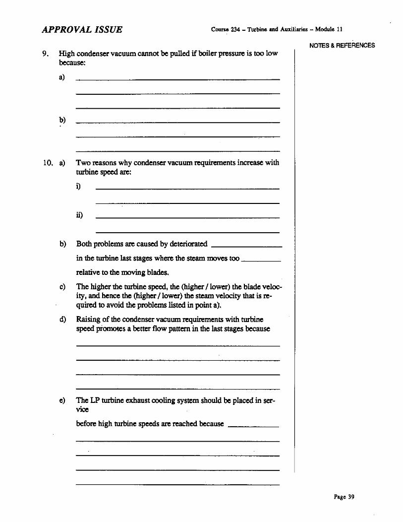
APPROVAL ISSUE Course 234 _ Turbine and Auxiliaries - Module 11
9. High condenser vacuum cannot be pulled ifboiler presswe is too lowbecause:
a)
b)
10. a) Two reasons why condenser vacuum requirements increase withturbine speed are:
i)
ii)
b) Both problems are caused by deteriorated _
in the turbine last stages where the steam moves too _
relative to the moving blades.
c) Tlte higher the turbine speed. the (higher / lower) the blade velocity. and hence the (higher / lower) the steam velocity that is required to avoid the problems listed in point a).
d) Raising of the condenser vacuum requirements with turbinespeed promotes a better flow pattern in the last stages because
e) The LP turbine exhaust cooling system should be placed in service
before high turbine speeds are reached because _
NOTES & REFERENCES
Page 39

Course 234 _ Turbine and Auxiliaries - Module 11 APPROVAL ISSUE
NOTES & REFERENCES11. The maior operational concerns that affect the startup and loading of a
turbine generator are:
a)
b)
c)
d)
e)
t)
12. a) Thermal stresses are created when thermal _
or is blocked. This can be caused by:
i)
ii)
b) An uneven temperature distribution within one component produces:
i) Tensile thermal stresses in its (cooler I hotter) parts because
ii) Compressive thermal stresses in its (cooler I hotter) parts
because _
c) Maximum thermal stresses exist during steady operation at fullpower when the HP turbine inlet steam is at its highest temperature. (Faise I true)
Page 40

APPROVAL ISSUE Course 234 - Turbine and Auxiliaries - Module 11
NOTES & REFERENCESd) During runup, loading, unloading or load rejection, large thenna!
stresses are produced. (False I true) The reason for this is
e) In large turbines, it may take a few hours before the most remoteparts of the casing and totor reach their normal operating temperature. (False I true)
13. The following abnormal operating conditions or accidents can producelarge thennaI stresses:
a) Condition:
It can produce large thenna! stresses because
b) Condition:
It can produce large thenna! stresses because
c) Condition:
It can produce large thenna! stresses because
Page 41
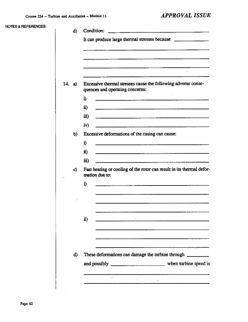
Course 234 - TUIbine and Auxiliaries - Module 11 APPROVAL ISSUE
NOTES & REFERENCESd) Condition:
It can produce large thenna! stresses because _
14. a) Excessive thennal stresses cause the following adverse consequences and. operating concerns:
i)
ii)
iii)
iv)
b) Excessive deformations of the casing can cause:
i)
ii)
iii)
c) Fast beating or cooling of the rotor can result in its thenna! deformation due to:
i)
ii)
d) These deformations can damage the turbine through _
and possibly when turbine speed is
Page 42

APPROVAL ISSUE Course 234 - Turbine and Auxiliaries - Module 11
NOlES & REFERENCES15. a) Cycling of thermal stresses is caused by alternate _
and of the turbine during operating conditions
such as _
b) Thermal cycling, if large enough, can result in fonnation of
c) !fnot repaired in time, they can cause -
d) The number of cycles to failure can be drastically reduced when
the stress level is _
0) !fthere are no acote symptoms, the permissible runup and loading rates can be safely exceeded with no adverse consequences tothe turbine. (False I true)
16. a) During turbine startup and loading, excessive thermal stresses areprevented by the following general operating practices:
i)
ii)
iii)
iv)
b) Three types of turbine startups are: _
They are based on
c) The proper runup and loading rates are selected as follows:
i) SLOW rates for startup;
ii) MEDIUM rates for startup;
i) FAST rates for startup.
Page 43
Course 234 - Turbine and Auxiliaries - Module 11 APPROVAL ISSUE
NOTES & REFERENCESd) A cold turbine must be run up and loaded (slowly I quickly) to
prevent _
e) A hot turbine must be tun up and loaded (slowly I quickly) to
prevent _
17. a) When the turbine generator is cold, its rotor and casings can be
too to withstand _
stresses.
b) Doring turbine startup. such stresses can be created doe to:
i)
il)
iii)
c) To avoid catastrophic failore. the torbine generator must be pr0p
erly JlI"warmed. This is performed when the turbine is
_________ and continued doring _
d) Turbine rotors are JlI"Warriled in the following ways:
i)
il)
Page 44

APPROVAL ISSUE Course 234 - Turbine lUld Auxiliaries - Module 11
e) For generator rotors, the following methods of prewanning areused:
i)
ii)
18. a) The tenn axia1 differential expansion means _
b) There are three reasons why ADE occurs in steam turbines:
i)
ii)
iii)
19. a) The lIP and LP turbine casings (dol do not) expand indepen
dently from one another because
b) The lIP turbine rotor (does I does not) expand independently
from the other rotors because _
c) The LP turbine rotor expansion (is I is not) cumulative because
20. a) At steady power, the rolOr is usually (cooler I hotter) than the
casing because ,..- _
NOTES & REFERENCES
Page 45

Coune 234 - Turbine and Auxiliaries - Module 11 APPROVAL ISSUE
NOTES & REFERENCESb) During lI3Jlsient operating conditions, the rotor expands (faster
I more slowly) than the casing because _
21. a) The Poisson's effect can be described as _
b) This effect influences the ADE of the (lIP ILP I all) turbine(s)
during _
22. a) Except for accidents, the maximum ADE occurs at full power.(False I true)
b) The steady state ADE can be defined as _
c) The lI3Jlsient ADE can be defined as
23. a) During startup, power manoeuvres or load rejections, ADE can
become particularly large because
b) Examples of some other operational causes of large ADE are:
i)
It can inerease ADE because _
il)
It can increase ADE because _
Page 46

APPROVAL ISSUE
Iii)
Course 234 - Turbine and Auxiliaries - Module 11
NOTES & REFERENCES
It can increase ADE because _
iv)
It can increase ADE because __--'- _
24. 0) Excessive ADE causes the following adverse consequences andoperating concerns:
i)
ii)
Iii)
b) Axial rubbing between the turbine stationary and moving parts
can damitge components such as
It can also increase rotor vibration due to _
25. The following general operating practices are used during turbine startup and loading in OllIer to prevent excessive ADE:
0)
b)
c)
d)
Page 47
Course 234 _ Turbine and Auxiliaries - Module 11 APPROVAL ISSUE
NOTES & REFERENCES26. The following actions may have to be perfonned. in response to exces
siveADE:
a)
b)
c)
d)
27. a) Holding turbine speed or load constant when excessive ADE is
indicated during turbine runup or loading, Iespectively, can re
duce the ADE because
b) When the ADE indicates that the rotor is too short relative to the
casing, a load (in...,...' Ieduetion) can return the ADE to nonna!
because
c) Tripping the turbine when the ADE indicates along LP turbine
rotor may actually cause damage because _
Before you move on to the next module, review the objectives and makesure that you can meet their requirements.
Prepuod by: J. Jung. BNTD
Revised by: J. Jung, ENTD
Revision date: July, 1994
Page 48

APPROVAL ISSUE Course 234 - Turbo. ..nd Auxiliaries - Module 11
Commencement}-...;;.PI;",,~,~,g!::~~.,..-{ }--:O~f~W~.::,m~'=,g!70f~~
4. Boiler Feed 5 Boiler and: -'. System lIS Steam ?lpelines
W········..r -i:P='''''::�='~g~the~T~"='''::',~·;,+----l~BGoverning System lIS
Placing theCondensate System I/S
'.Placing the Placing the .
Turbine rurbina Placing the Turbineh==,+{ 2 }-.,'7:::;:;;',+{ 3 )-----'-='";S;=::;:::::;::----.{Sup9fVisory Lube Oil on Turning Gear
System 1/5 System liS
Placing the CCW System in SerVice
Initial State:
EXTENDEDSHlJTDQWN
> -=:~C~O~'::"='"~.=tio~'~O=f=w..m::;<='og~::-_-__""'IA the Boilers and Steam Pipelines tv··· 10Placing the LP Turbine
Exhaust CoolingSystem lIS
Prerunup Checks Commencement ofB >----10{ 7 }----=;;;,:"='''''='~:'=:----< 9 }-----':::;:c;;:;::'i2":"-'-----< 11}---<~of Turbine Steam ValvBS Turbine Runup
~ote2Placing the
C>,~G;;~="";:;;:se::;:aJ=',~gb;-....-{ • }--=-_C"o~m~m~.~'~oa~m""."'~of"""..~Ba }-_--:,..-""'C=OO~'~·,~""='=·OO=O~f..". -'Steam System liS Condenser \tlculJfTI PUlling Condenser \9cuum PUlling
(Note 1)
Final State:
}_--'!l!!""'''''~''''''~a~tio~''--_~ }__-=loa""'~~·''"___....-<" '4 UNIT ATFULL POWER
Fig. 11.6. Major activities during starlUp and loading of the steam and feedwater cycle systems.--------i... Activities Additional cross-links
Noff1s:1. In some ststions, this activity is delayed untD.IiI certain level of condenser vacuum has been reached.2. AppJlgs to the slstions where steam jet sir ejectors sre used.
Page 49