Module 2 Electronics, Safety & Careers – Electronic Components & Symbols ... functions within an...
34
Radio Merit Badge Boy Scouts of America Module 2 Electronics, Safety & Careers BSA National Radio Scouting Committee2012
Transcript of Module 2 Electronics, Safety & Careers – Electronic Components & Symbols ... functions within an...

Radio Merit Badge Boy Scouts of America
Module 2
Electronics, Safety & Careers BSA National Radio Scouting Committee2012

Three modules – any order
Module 1 – Intro To Radio
Module 2 – Electronic
Components & Safety
Module 3 – Amateur Radio &
Emergency Communications ..
Class Format

4 – How Radio Carries Information
5a – Radio Schematic Diagrams
5a, 5b – Radio Block Diagrams
5c – Types of Electrical Circuits
5d – Electronic Components & Symbols
6 – Radio Safety
8 – Careers in Radio
Key Topics in This Module

Modulation – Superimposing information (audio, data, video)
onto a radio signal
.
Modulation
Un-modulated radio carrier Carrier modulated with audio
Requirement 4

How Do Radio Waves Carry
Sounds or Information?
FM
AM
PM
Requirement 4

Continuous Wave (CW)
The Oldest Digital Mode
Works by simply turning the transmitter
on and off in a pattern called Morse Code.
Requirement 4

“CW” or Morse Code
No longer required to know, but still popular among ham radio
operators. Needs less power and bandwidth than other ‘modes”.
Requirement 4

.
Modern Components
Requirement 5d

..
Older Components
Requirement 5d
..
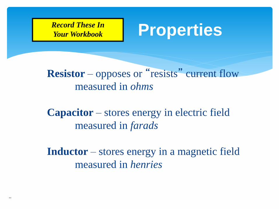
Properties
Resistor – opposes or “resists” current flow
measured in ohms
Capacitor – stores energy in electric field
measured in farads
Inductor – stores energy in a magnetic field
measured in henries
Record These In
Your Workbook

Conductors conduct (carry) electricity. Most metals (gold, silver, aluminum, copper)
Many liquids (water)
Insulators insulate (don’t carry) electricity. Air
Most rubbers and plastics
Most ceramics
Wood and cloth (when dry and at low voltage)
Conductors & Insulators
Direct Current (DC) – flows only one direction;
produced by battery
Alternating Current (AC) – flows in first one direction
then another; found in our home electrical outlets
..
Types of Electrical Current

Voltage – electrical pressure (volts)
Current – the flow of electricity through a circuit (amps)
Power – the ability to do work (watts)
.
Basic Electrical Terms

.
Block Diagram vs. Schematic
Audio
Signal
Pre
Amp
RF
Oscillator
Mixer
Carrier
Signal
Final
Amp Modulated
RF Signal
Block Diagram:
Outlines the various
functions within an
electronic device Input Output
Schematic
Diagram: Uses
standard electrical
symbols to describe
an electrical circuit
in detail
LED flashlight
+
3V
Switch 120 ohm
Radio Transmitter
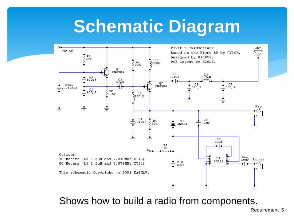
Schematic Diagram
Shows how to build a radio from components. Requirement 5

Schematic Symbols
Fuse
Contains a thin wire which is made to melt which protects the rest of the
circuit from damage if there is too much current from a short circuit.
Battery
Stores electric energy.
Resistor
Resists the flow of electric current, reducing its flow.
Variable
resistor
Like a regular resistor, but adjustable. For example, the volume knob on your
stereo.
Earth
ground
A connection between the equipment (radio) and the earth, usually through a
copper pipe driven into the soil.
Chassis
ground
A connection of the negative side of the electronic circuit to the chassis, or
steel frame, of the equipment.
Requirement 5
Represent Individual Electronic Parts (“Components”)

Schematic Symbols (cont.)
Capacitor
Gets and stores an electric charge. Lets alternating current (AC - like in your
house) flow but stops direct current (DC - like from a battery).
Variable
capacitor
Same as a regular capacitor, but adjustable.
NPN
transistor
Amplifies a current.
PNP
transistor
Amplifies a current.
Coil
Also called a choke, it works the opposite of a capacitor. It lets DC flow but
stops AC.
Tube
A vacuum tube made of glass with wire filaments inside. Amplifies a current. It
has been replaced by transistors in most home equipment, but is still found in
some high power radio transmitters.
Requirement 5

Schematic Symbols (cont.)
Antenna
Sends radio frequency signals into the air.
SPST
switch
Single-pole single-throw switch. Has two positions, on and off. Like most light switches
DPDT
switch
Double-pole double-throw switch. A double-throw switch has three positions. It can
switch one input to one of two outputs - sort of like the switch you put on your television
to switch between watching TV and playing your video game. The double-pole means it
can switch a pair of inputs to either of two pairs of outputs.
Requirement 5
.
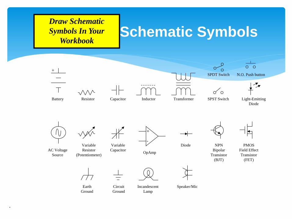
Schematic Symbols
+
Resistor SPST Switch Light-Emitting
Diode
Battery Capacitor Inductor Transformer
SPDT Switch
Diode NPN
Bipolar
Transistor
(BJT)
PMOS
Field Effect
Transistor
(FET)
Variable
Capacitor
Variable
Resistor
(Potentiometer)
N.O. Push button
AC Voltage
Source
Earth
Ground
Circuit
Ground
+
-
OpAmp
Incandescent
Lamp
Speaker/Mic
Draw Schematic
Symbols In Your
Workbook

.
How Radio Waves Are Created
Mic
Audio
Signal
Pre
Amp
RF
Oscillator
Mixer
Carrier
Signal
Final
Amp
Feed Line
Antenna
Basic AM Transmitter
Modulated
RF Signal
•Transmitter - Generates radio frequency (RF) signal
•Amplifier - Makes the signal stronger and drives feed line
•Antenna - Launches the electromagnetic wave into the air

Microphone Takes in Audio or Digital signal input
Transmitter Creates an RF “carrier”
Modulates the carrier
Receiver Receives a radio signal
Demodulates the carrier
Transceiver Both a transmitter and receiver in one box
Amplifier Increases RF signal power
Tuner Matches transmitter to antenna
Feed line Provides path to antenna
Antenna Radiates the RF signal
Key or Paddle For sending Morse code
TNC (Terminal Node Controller) A computers “Radio Modem”
How Radios Send and Receive
Information
Transceiver Amplifier Tuner
Microphone
Key/Paddle
TNC Computer
Requirement 4

Simplified Block Diagram
Transceiver Amplifier Tuner
Microphone
Key/Paddle
TNC Computer
Shows how station
components are
connected together.
Antenna
Requirement 5
Feed Line

Detailed Block Diagram
Shows how the radio works. Requirement 5

Closed Circuit Circuit is complete. Electricity flows like it should.
Open Circuit Circuit is incomplete. Electricity doesn’t flow.
Short Circuit Circuit is complete through an unplanned shortcut. Electricity flows where it shouldn’t! Dangerous – parts can get hot, start fires or even explode!
Types of Electrical Circuits
Requirement 5
+ 3V
S1 120 ohm
Current Flow
LED flashlight
+ 3V
S1 120 ohm
Current Flow
LED flashlight
On
Off
Fuse

Never operate radios with the cover off.
The case keeps the RF radiation in.
Exposure to high levels of RF can cause burns
Human eyes especially sensitive to RF.
Keep antennas out of reach.
Hams required to conduct a “routine station
evaluation” to verify safe operation
Usually done by consulting a chart.
.
Safety With RF Energy

Make sure the power is disconnected before working.
Electric shock can hurt or kill.
Even with the power off, some parts inside the radio can hold a dangerous charge.
If you don't know what you are doing, get help.
Disconnect radios when not in use
Connect antennas to ground when not in use
Radio Safety
Requirement 6
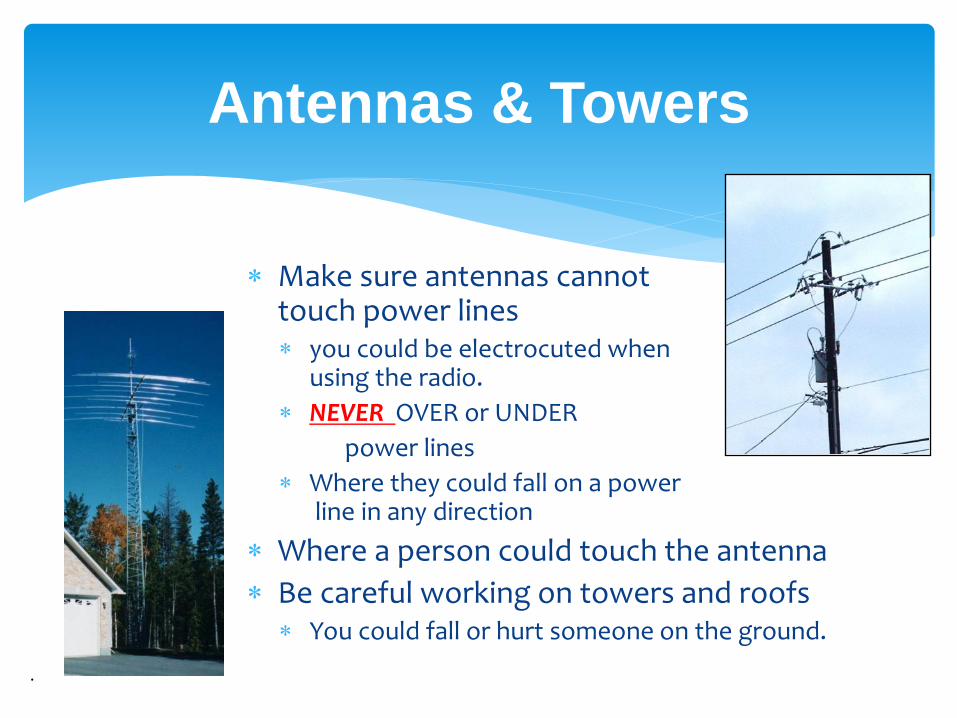
Make sure antennas cannot touch power lines you could be electrocuted when
using the radio.
NEVER OVER or UNDER
power lines
Where they could fall on a power line in any direction
Where a person could touch the antenna
Be careful working on towers and roofs You could fall or hurt someone on the ground.
.
Antennas & Towers

AC Outlet Grounding Ground wire connected to house wiring.
Equipment uses 3 prong plugs to ground equipment case.
If wire inside touches case, house circuit breaker is opened.
Direct Current Grounding Hams add another ground rod and connect all of their station
equipment cases to it as well.
Provides additional safety and grounds any stray RF.
Antenna Grounding Use lightning protectors where antennas enter the house.
These bleed off static electricity.
No protection to a direct strike.
Grounding
Requirement 6

Antenna pole connected to ground rod
Disconnect radios if lightning is in the area
Lightning can hit your
antenna and travel down your
lines to the radio.
Make sure your antenna and
radio are grounded to a good
earth ground.
Don’t operate in
thunderstorms.
.
Lightning Protection

Minimum fatal voltage – 30 volts
Minimum fatal current if passed through the human
heart – 1/10th of an amp
Power lines are un-insulated and carry thousands of
volts – never touch them!
.
Safety With Electricity

Broadcasting Announcer/Personality
Station Manager/Program Director/ Music Director
Technical Radio Engineer
Radio Technician
Cellular Phone Technician
Operators Public Safety Dispatcher
Military Radio Operator
Radio Careers
Requirement 8

Most jobs require high school diploma.
Colleges offer courses in broadcasting and communications.
Gain broadcasting experience at college radio stations.
Radio technicians attend trade schools or community colleges.
Radio engineers study electrical engineering at college.
Organizations such as APCO and NARTE offer radio licensing training courses and certifications.
Education for Radio Careers
Requirement 8