Module 14 Conventional Filtration - PA.Gov
83
Drinking Water Operator Certification Training Module 14 Conventional Filtration This course includes content developed by the Pennsylvania Department of Environmental Protection (Pa. DEP) in cooperation with the following contractors, subcontractors, or grantees: The Pennsylvania State Association of Township Supervisors (PSATS) Gannett Fleming, Inc. Dering Consulting Group Penn State Harrisburg Environmental Training Center Updated: February 2012
Transcript of Module 14 Conventional Filtration - PA.Gov
Drinking Water Operator Certification Training
Module 14
Conventional Filtration
This course includes content developed by the Pennsylvania Department of Environmental Protection (Pa. DEP) in cooperation with the following contractors, subcontractors, or grantees:
The Pennsylvania State Association of Township Supervisors (PSATS)
Gannett Fleming, Inc. Dering Consulting Group
Penn State Harrisburg Environmental Training Center
Updated: February 2012
MODULE 14: CONVENTIONAL FILTRATION
Bureau of Safe Drinking Water, Department of Environmental Protection Drinking Water Operator Certification Training i
Topical Outline
Unit 1 – Conventional Water Treatment Overview I. Purpose of Conventional Water Treatment
A. Compliance with Regulations
B. Production of Safe Drinking Water II. Terms and Definitions
A. Clarification
B. Coagulation
C. Colloids
D. Conventional Filtration
E. Disinfection
F. Floc
G. Flocculation
H. Sedimentation
I. Sludge
J. Turbidity
III. Conventional Water Filtration Process Flow
A. Source Water
B. Chemical Addition
C. Pretreatment
D. Filtration
E. Disinfection
F. Corrosion Control
G. Water Distribution
MODULE 14: CONVENTIONAL FILTRATION
Bureau of Safe Drinking Water, Department of Environmental Protection Drinking Water Operator Certification Training ii
Unit 2 – Mixing, Coagulation, and Flocculation I. Mixing II. Coagulation
A. Coagulant Chemicals
B. Basic Coagulant Chemistry
C. Process Control
D. Chemical Safety III. Flocculation
A. Floc Formation
B. Performance Considerations
C. Types of Flocculators
D. Flocculation Basins Unit 3 – Sedimentation/Clarification I. Principles of Operation
A. Settling Characteristics
B. Sedimentation Basin Characteristics
C. Operating Parameters II. High Rate Sedimentation Process
A. Tube or Plate Settlers
B. Specialized Processes III. Sedimentation Mathematical Calculations
A. Theoretical Detention Time
B. Surface Loading
C. Mean Velocity
D. Weir Loading Rate
MODULE 14: CONVENTIONAL FILTRATION
Bureau of Safe Drinking Water, Department of Environmental Protection Drinking Water Operator Certification Training iii
Unit 4 – Filtration I. General Overview of Conventional Filtration
A. Process Description
B. Filtration Mechanisms II. Types of Filters
A. Gravity
B. Pressure III. Filter Control Systems
A. Purposes
B. Common Control Systems
IV. Performance Considerations
A. Filter Media
B. Filter Underdrains
C. Operational Criteria
D. Backwashing V. Process Calculations
A. Filtration Rate
B. Backwash Rate VI. Record Keeping

MODULE 14: CONVENTIONAL FILTRATION
Bureau of Safe Drinking Water, Department of Environmental Protection Drinking Water Operator Certification Training iv
Unit 5 – Operation of Conventional Filtration Facilities I. Normal Operation
A. Process Performance Monitoring
B. Process Controls and Equipment
C. Process Support Equipment
D. Housekeeping
E. Laboratory Testing II. Process Start-up and Shutdown Procedures
A. Start-up Procedures
B. Shut Down Procedures III. Abnormal Operation
A. Changes in Source Water Quality
B. Increased Filtered Water Turbidity
C. Record Keeping IV. Conventional Filtration Process Trouble Shooting
A. Source Water Quality
B. Process Quality – Coagulation/Flocculation
C. Process Quality – Sedimentation
D. Process Quality – Filtration
Bureau of Safe Drinking Water, Department of Environmental Protection 1-1
Drinking Water Operator Certification Training
Unit 1 – Conventional Water Treatment Overview
Learning Objectives
Use vocabulary appropriate to conventional filtration of water in discussing the process.
Follow the Typical Process Flow Diagram and identify the four major conventional filtration processes.

PURPOSE OF CONVENTIONAL WATER TREATMENT
Bureau of Safe Drinking Water, Department of Environmental Protection 1-2 Drinking Water Operator Certification Training
The purpose for Conventional Water Treatment is two-fold.
Compliance with Regulations
The primary purpose is to comply with the Environmental Protection Agency (EPA) and Pennsylvania Department of Environmental Protection (Pa. DEP) regulations requiring filtration as a mandatory "treatment technique" for all surface water supplies. This "treatment technique" must be operated so as to produce filter effluent that has turbidity less than 0.3 ntu in 95% of all monthly samples taken at four-hour intervals. For more information on this regulation see Module 1.
Production of Safe Drinking Water
Additionally, it is critical to consistently and reliably produce safe and aesthetically acceptable drinking water. To achieve this on a regular basis, water treatment facilities will normally operate facilities focused on treatment goals that are below the regulatory Primary Maximum Contaminant Levels for those contaminants that present health risks based on acute or chronic exposure. These include certain metals and organic compounds, as well as radionuclides and microbiological contaminants. To provide drinking water that is free of tastes, odors and staining or scaling properties, operators typically establish treatment goals that are below the Secondary Maximum Contaminant Levels. These include iron, manganese, tastes, odors, calcium and others. See Module 1 for a list of the Primary and Secondary Contaminants.

TERMS AND DEFINITIONS
Bureau of Safe Drinking Water, Department of Environmental Protection 1-3 Drinking Water Operator Certification Training
Clarification – The removal of floc and heavier suspended matter, typically by gravity settling.
Coagulation – The use of coagulant chemical to promote aggregation of small and colloidal particles into larger "floc" particles. The coagulant chemical neutralizes the electrical charge on the surface of the small particles, resulting in destabilization of the colloidal suspension.
Colloids – Very small, finely divided solids that remain dispersed in a liquid for a long period of time due to their very small size and common electrical charges. Due to the common electrical charges, the particles tend to repel each other, preventing the particles from merging and forming heavier particles. The colloidal particles with common charge actually repel each other similarly to magnets when similar poles are placed near each other. This phenomenon actually causes the particles to remain in suspension, unless destabilized by the coagulant.
Conventional Filtration – A method of treating water which consists of the addition of coagulant chemicals, flash mixing, coagulation and flocculation, sedimentation, filtration and disinfection.
Disinfection – The process designed and operated to inactivate or remove pathogenic microorganisms in the water, including bacteria, virus, and protozoan cysts. The conventional process will disinfect water by removing these microorganisms through the clarification and filtration process and inactivating them with chemical disinfectants such as chlorine or rendering them non-infective with ultraviolet light. The water treatment process must include this multi-barrier approach to disinfection.
Floc – Aggregations of particulate impurities that have formed in a cluster. The formation of appropriate size and density of floc particle is critical to the performance of the subsequent clarification process. Density and size is normally a function of the particles in the water but is also impacted by the chemical coagulant, mixing energy and detention time in the floc basin.
Flocculation – The process of forming floc particles from coagulated colloidal matter typically accomplished in a separate process basin with a residence time of 20 to 30 minutes and including gentle mixing to promote inter-particle contact.

TERMS AND DEFINITIONS
Bureau of Safe Drinking Water, Department of Environmental Protection 1-4 Drinking Water Operator Certification Training
Sedimentation –The process of clarifying water by gravity settling of the floc particles.
Sludge – The settleable solids separated from the water during processing.
Turbidity –The clarity of water is measured by passing a light beam through the water and measuring how much of the light is reflected by the particles in the water. The instrument used to measure clarity is called a turbidimeter and the cloudy appearance of water is referred to as turbidity. Nephelometric turbidity units (ntu) are typically used to quantify the performance of the clarification and filtration process. Raw source water may have turbidity readings anywhere from 1 to more than 1000 ntu. The goal for clarification is typically less than 1 ntu. Filtration must result in turbidity less than 0.3 ntu, and is normally less than 0.10 in an optimized filter plant.

CONVENTIONAL WATER FILTRATION PROCESS FLOW
Bureau of Safe Drinking Water, Department of Environmental Protection 1-5 Drinking Water Operator Certification Training
Conventional Filtration
Source Water (Covered in Modules 2 and 3)
Chemical Addition
(Covered in Module 21)
Pretreatment (Covered in Module 14 -- Units 2 and 3)
Mixing/Coagulation
Flocculation
Sedimentation
Filtration (Covered in Module 14 -- Unit 4)
Disinfection (Covered in Modules 5, 24 through 27)
Corrosion Control (Covered in Module 20)
Water Distribution (Covered in Modules 8, 9, and 28)
Figure 1.1 – Process Flow

UNIT 1 EXERCISE
Bureau of Safe Drinking Water, Department of Environmental Protection 1-6 Drinking Water Operator Certification Training
UNIT 1 EXERCISE Complete the crossword puzzle as a vocabulary review.
Across
3. The use of a coagulant chemical to promote aggregation of small and colloidal particles into larger "floc" particles. The coagulant chemical neutralizes the electrical charge on the surface of the small particles, resulting in destabilization of the colloidal suspension.
6. The process of forming floc particles from coagulated colloidal matter typically accomplished in a separate process basin with a residence time of 20 to 30 minutes and including gentle mixing to promote inter-particle contact.
7. The process of clarifying water by gravity settling of the floc particles.
8. Aggregations of particulate impurities that have formed in a cluster. Density and size is normally a function of the particles in the water, but is also impacted by the chemical coagulant, mixing energy and detention time in the floc basin.
10. Very small, finely divided solids that remain dispersed in a liquid for a long period of time due to their very small size and common electrical charges.
Down
1. The clarity of water is measured by passing a
light beam through the water and measuring how much of the light is reflected by the particles in the water.
2. A method of treating water which consists of the addition of coagulant chemicals, flash mixing, coagulation and flocculation, sedimentation, filtration and disinfection.
4. The removal of floc and heavier suspended
matter, typically by gravity settling.
5. The process designed and operated to inactivate or remove pathogenic microorganisms in the water.
9. The settleable solids separated from the water during process.
1
2
3
4
5
6
7
8
9
10

UNIT 1 SUMMARY
Bureau of Safe Drinking Water, Department of Environmental Protection 1-7 Drinking Water Operator Certification Training
Unit 1 Key Points
Conventional Filtration consists of coagulation, flocculation, sedimentation and filtration.
Colloidal particles in water do not settle readily.
The gentle agitation of coagulant treated water for an appreciable period of time is known as flocculation.
Inlets or gates should be located in a raw water reservoir intake so that water can be taken from multiple depths.
Bar screens (or racks) are used to remove large objects which may damage plant equipment.
Bureau of Water Supply and Wastewater Management, Department of Environmental Protection 2-1 Drinking Water Operator Certification Training
Unit 2 – Mixing, Coagulation, and Flocculation
Learning Objectives
List the major chemicals used in the coagulation process and explain their importance to the process.
Explain the importance of flocculation to conventional filtration.
List two types of mechanical flocculators in common use.

COAGULATION
Bureau of Water Supply and Wastewater Management, Department of Environmental Protection 2-2 Drinking Water Operator Certification Training
Mixing – The introduction and uniform dispersal of chemicals into the water in as short a time period (rapid) as possible.
Besides distributing a coagulant evenly through the water, rapid mixing is to encourage collisions
between suspended particles.
Baffle
WallFlocculator (typ)Baffle
Wall
Rapid
Mixer
pH
Adjustment
Chemicals
CoagulantCoagulant
Aid
FlocculationFlash Mixing/
Coagulation
Figure 2.1 - Mixing, Coagulation & Flocculation Schematic
Mixing Methods There are two methods for Mixing: Hydraulic and Mechanical. Hydraulic Mixing Uses the hydraulic energy of the flowing water. Is often called Static Mixing.
Figure 2.2 - Static Mixer 1
Mechanical Mixing Mechanical equipment is used to stir the water. This equipment has propeller that usually have a vertical
orientation.
Figure 2.3 - Mechanical Mixer 2

COAGULATION
Bureau of Water Supply and Wastewater Management, Department of Environmental Protection 2-3 Drinking Water Operator Certification Training
Coagulant Chemicals All chemicals used in the water treatment process must be approved by both the Environmental Protection Agency (EPA) and the Department of Environmental Protection (DEP) for potable water use. Primary Coagulants The following chemicals are those used most often in coagulation. They cause the non-settleable particles to become destabilized and begin to clump together. Remember the definition in Unit 1 - colloidal particles in water do not settle. Metallic salts
o Aluminum Sulfate (Alum) – Al2(SO4)3 • 14 H2O
Addition of Alum will suppress the water’s alkalinity. Addition of lime may be required to replace lost alkalinity.
When dissolved in water Alum produces ions that are positively charged.
o Ferric Sulfate - Fe2(SO4)3 • 9 H2O
o Ferric Chloride - FeCl3 • 6 H2O
A major advantage of using ferric salts instead of alum is that they are more effective over a broader pH range.
The greatest safety hazard involved with the use of ferric chloride is corrosiveness.
Synthetic inorganic polymers
o Polyaluminum Chloride - Aln(OH)mCl(3n-m) • H2O Coagulant Aids Chemicals used to strengthen and add density to the flocs. Synthetic organic polymers
o Commonly referred to as polyelectrolytes
o Cationic – positively charged
o Adsorb on negatively charged particles (turbidity) to neutralize the charge. Forming an interparticle bridge which traps particles.
Inorganic Chemicals Chemicals used to add density to the flocs. Bentonite Clay Lime

COAGULATION
Bureau of Water Supply and Wastewater Management, Department of Environmental Protection 2-4 Drinking Water Operator Certification Training
Basic Coagulant Chemistry Dissolved Organic Matter Dissolved organic matter is preferentially coagulated and exerts a higher demand than turbidity. pH dependent pH dependent – Lower pH values tend to favor positively charged compounds which are desirable for reacting with the negatively charged turbidity particulates. Best pH range is 5 to 7.
o The lower part of range is better for coagulation of organics.
Proper pH must be maintained—coagulants react with alkalinity in the water. Natural alkalinity helps to maintain the pH and aids in the complete precipitation of the coagulant
chemicals. Low raw water alkalinity can be increased by the addition of lime or soda ash. High pH can be reduced with the addition of acid. Both overdosing and under dosing of coagulants reduce solids removal efficiency.
Process Control
Plant operators must be able to measure and control plant performance on a day-to-day basis depending on variability of source water. The most important consideration is the selection of the proper type and dosage of coagulant chemical(s). Jar Test Tests should be performed at least daily. Tests should be performed whenever the raw water quality changes. Tests should be performed whenever changes are made to the type of coagulant chemicals.

COAGULATION
Bureau of Water Supply and Wastewater Management, Department of Environmental Protection 2-5 Drinking Water Operator Certification Training
During the coagulation/flocculation process, floc that is too large may be caused by chemical addtion at the wrong point.
For best results in a plant equipped with a flash mix basin, coagulant should be added to the
influent line just ahead of the flash mix basin. Complete flocculation will not form if rapid mixing is too slow. Adjust speeds when desired
flocculation demonstrated in the jar test is not achieved.
Calculate the dosage, if 1500 pounds of dry Alum are required to treat 15- mgd of water.
Chemical Safety When handling and preparing water treatment chemicals, wearing appropriate personal protection equipment is critical. Material Data Safety Sheets (MSDS) provide information on:
o Chemical handling
o Personal safety
o First Aid
o Chemical disposal
o Spill and clean-up
o Specific gravity
o CAS#, Chemical name(s)
o Chemical properties
Secondary containment is required for storage of hazardous materials. Refer to the manufactures and MSDS on chemical storage. Shelf-life should be noted. This is
especially important when mixing up a batch of chemical; the strength will degrade over a period of time.

FLOCCULATION
Bureau of Water Supply and Wastewater Management, Department of Environmental Protection 2-6 Drinking Water Operator Certification Training
Floc Formation Floc formation is controlled by three factors: The effectiveness of coagulation, The rate at which collisions occur, and The effectiveness of collisions in promoting attachment between particles. Stable colloidal
suspensions will not floc well.
Performance Considerations
Effectiveness of sedimentation, filtration, and overall plant performance depends on successful coagulation/flocculation. The goal is to remove as much turbidity in this process before moving onto filtration. Stirring Efficient flocculation involves the proper stirring time (detention time), proper stirring intensity, proper shaped basin for uniform mixing, and a means of creating the stirring action. Flocculation is best accomplished by a gently mxing. Insufficient stirring will result in ineffective collisions and poor floc formation. Excessive stirring may tear apart flocculated particles after they have clumped together. Detention Time Usually not a critical factor in flash-mixing or coagulation.
o It is usually satisfactory if the chemicals are dispersed and mixed with the water for several seconds.
Extremely important in the flocculation process.
o It is required for the necessary chemical reactions to occur.
o A 20 to 30 minute flocculation period is necessary.
An indication the coagulation/floccualtion is working well is, in the flocculation/sedimentation proces, well-formed, good-sized flocculation is entering the flocculation baisns, and a very small amount of verysmall-sized flocculation is going to the filters.

FLOCCULATION
Bureau of Water Supply and Wastewater Management, Department of Environmental Protection 2-7 Drinking Water Operator Certification Training
Disinfection Poor performance affects disinfection. Additional disinfectant is required to oxidize organic material that is not removed. This can result in
the formation of disinfection by-products following chlorine disinfection.
Bacteria and other pathogens can be bound up in suspended particles and shielded from the disinfectant.
Types of Flocculators
There are two types of mechanical flocculators in common use: The Horizontal Paddle Wheel Flocculator and the Vertical Flocculator. Both types provide satisfactory performance. Horizontal Paddle Wheel Flocculator
Figure 2.4 - Horizontal Paddle Wheel 3 Vertical Flocculators – Two Types Propeller or Turbine Paddle
Figure 2.5 - Vertical Paddle Wheel 4

FLOCCULATION
Bureau of Water Supply and Wastewater Management, Department of Environmental Protection 2-8 Drinking Water Operator Certification Training
Walking Beam Flocculator
Not as common, but still in use today.
Uses paddles moving in an up & down motion, like walking; rather than the circular motion common to both horizontal and vertical paddle type units.
Figure 2.6 - Walking Beam 5
Flocculation Basins
Size and Shape The size and shape of a flocculation basin is usually established by the design engineer. Generally, rectangular for horizontal type flocculators and square for vertical type flocculators. The depth is generally the same or deeper than the sedimentation basins. Compartments The best flocculation is usually achieved by using several smaller compartments (usually three or more) rather than one equivalent sized basin. Compartments are separated by baffles to prevent short-circuiting. The mixing intensity is generally reduced as flow passes through the compartments. This is called
tapered-energy mixing. It helps prevent breaking larger floc particles after they have formed.
Floc will settle out prematurely is the paddle wheel flocculator speed is set too slow.
UNIT 2 EXERCISE
Bureau of Water Supply and Wastewater Management, Department of Environmental Protection 2-9 Drinking Water Operator Certification Training
Unit 2 Exercise
1. List the primary coagulants (3 metallic salts and 1 synthetic inorganic polymer) used in the coagulation process.
2. In the space provided, explain the importance of coagulant aids—synthetic organic polymers.
3. List two types of mechanical flocculators in common use.
True/False: Mark those that are true with a T, those that are false with an F.
4. _____ The effectiveness of sedimentation, filtration and overall plant performance depends on successful coagulation/flocculation.
5. _____ Poor coagulation/flocculation does not affect performance.
6. _____ Alum will decrease pH, adding lime to the flash mixer will increase lost alkalinity.
7. _____ When dissolved in water, alum generally produces negatively charged ions.
8. _____ Using iron slats instead of alum for coagulation is less effective over a broader pH range.
9. _____ Adding chemicals at the wrong location may cause floc to be too large.
10. _____ Coagulants added in the influent line before a flash mix basin will produce better results.
11. _____ Mixing is the rapid uniform distribution of a chemical in the water being treated.
12. _____ Colloidal particles refer to the ions that settle out easily through gravity.
13. _____ If an operator observes floc splitting and breaking up in the flocculation chamber, the rate of the flocculators should be slowed down.
14. _____The main purpose of coagulation/sedimentation is to remove turbidity.
UNIT 2 SUMMARY
Bureau of Water Supply and Wastewater Management, Department of Environmental Protection 2-10 Drinking Water Operator Certification Training
Unit 2 Key Points
The main purpose of coagulation/sedimentation is to remove turbidity. The rapid uniform distribution of a coagulant or other chemicals in the water being treated is called
mixing. The purpose of rapid mixing is to distribute coagulant evenly throughout the water and to
encourage collisions between suspended particles. For best results in a plant equipped with a flash mix basin, coagulant should be added to the
influent line just ahead of the flash mix basin. The purpose of adding a coagulant aid is to increase floc strength and density. Alum is added to raw water as a coagulant. The effect this will probably have on the pH of the
water is to decrease it. Lime could be added to the flash mixer to replace alkalinity lost during the coagulation process.
When dissolved in water, aluminum sulfate generally produces ions that are positively charged. If
alum is used for coagulation at a pH above 9.0, increased dissolved aluminum will result in the filtered water.
A major advantage of using iron salts instead of alum for coagulation is that iron salts are more
effective over a broader pH range than alum. A problem with ferric chloride is its corrosive. During the coagulation/flocculation process, floc that is too large may be caused by chemical
addition at the wrong point. If an operator observed floc splitting and breaking up in the flocculation chamber, the flocculator
rate should be slowed down. In a flocculation/sedimentation process, well-formed, good-sized floc is entering the flocculation
basins, and a very small amount of very small-sized flocculation is going to the filters. This indicates that the coagulation/flocculation process is working well.
During the coagulation/flocculation process, if the rapid mix is too slow, complete floc will not form. Change of composition and break down of the chemical is a concern in diluting a chemical prior to
feeding. If heavy rains have occurred, causing source water turbidity to increase significantly, and additional
alum is added, a chemical to increase alkalinity may also be added to optimize coagulation. The purpose of a Material Safety Data Sheet is to provide information on chemical handling,
chemical properties, clean up of spills and personal safety.
UNIT2 REFERENCES
Bureau of Water Supply and Wastewater Management, Department of Environmental Protection 2-11 Drinking Water Operator Certification Training
1 “Static Mixer.” http://www.koch-glitsch.com (17 Jun. 2003). 2 “Mechanical Mixer.” http://www.lightnin-mixers.com (17 Jun. 2003).
3 “Horizontal Paddle Wheel.” http://www.myersequipment.com/products.html (26 May 2003).
4 ”Vertical Paddle Wheel.“ http://www.myersequipment.com/products.html (26 May 2003). 5 “Walking Beam.” http://www.myersequipment.com/products.html (26 May 2003).

Bureau of Safe Drinking Water, Department of Environmental Protection 3-1 Drinking Water Operator Certification Training
Unit 3 – Sedimentation/Clarification
Learning Objectives
List five operating parameters important to sedimentation.
Identify the four zones of a sedimentation basin.
Given the formula and required data, calculate each of the following: detention time, surface loading rate, mean flow velocity, and weir loading rate.
Explain why tube or plate settlers increase settling efficiency.
Identify five characteristics upon which the sedimentation process is dependent.
PRINCIPLES OF OPERATION
Bureau of Safe Drinking Water, Department of Environmental Protection 3-2 Drinking Water Operator Certification Training
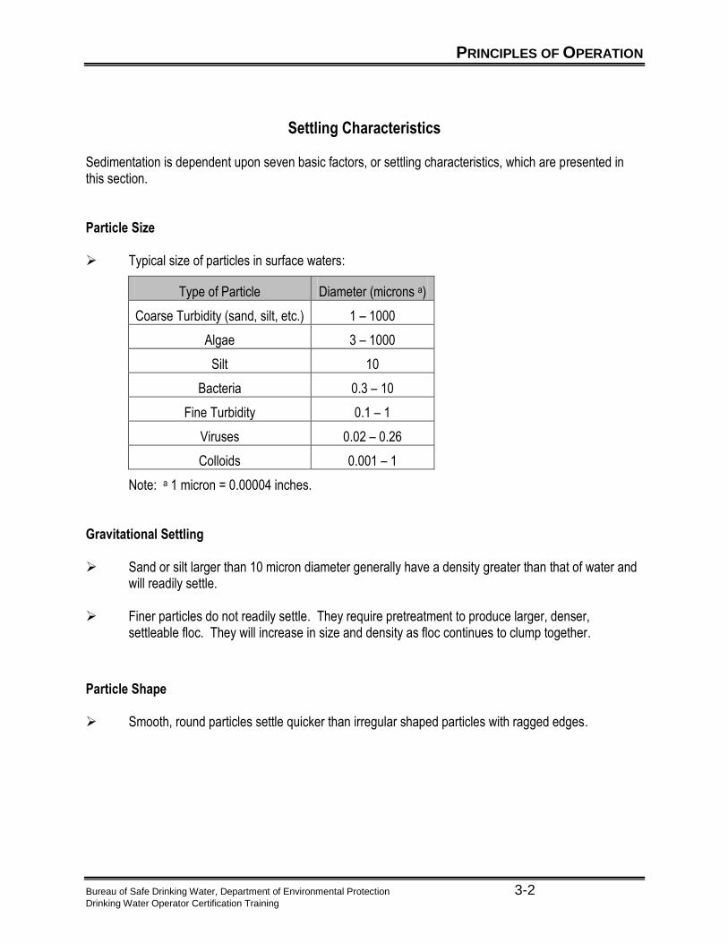
Settling Characteristics Sedimentation is dependent upon seven basic factors, or settling characteristics, which are presented in this section. Particle Size Typical size of particles in surface waters:
Type of Particle Diameter (microns a)
Coarse Turbidity (sand, silt, etc.) 1 – 1000
Algae 3 – 1000
Silt 10
Bacteria 0.3 – 10
Fine Turbidity 0.1 – 1
Viruses 0.02 – 0.26
Colloids 0.001 – 1
Note: a 1 micron = 0.00004 inches. Gravitational Settling Sand or silt larger than 10 micron diameter generally have a density greater than that of water and
will readily settle.
Finer particles do not readily settle. They require pretreatment to produce larger, denser, settleable floc. They will increase in size and density as floc continues to clump together.
Particle Shape Smooth, round particles settle quicker than irregular shaped particles with ragged edges.

PRINCIPLES OF OPERATION
Bureau of Safe Drinking Water, Department of Environmental Protection 3-3 Drinking Water Operator Certification Training
Relationship of Downward Movement of Particle to Forward Flow Velocity Water must remain in the basin long enough for a particle at the surface to fall through the basin
depth until captured in the sludge zone.
o The time it takes for a particle at the surface to fall to the bottom must be shorter than the time it takes for it to be carried from the inlet to the outlet.
o Sedimentation is improved by uniform low velocity flow across the basin.
Short Circuiting – When water has a shortened flow path. The detention time within the sedimentation process is reduced. Therefore the process is not as effective.
Water Temperature
Water reaches maximum density at 40 C.
o Water expands as temperature increases (above 4º C) and contracts as temperature decreases to 40 C.
o Once the water has reached its maximum density (40 C) and the temperature continues to drop, the opposite is true. That is, as the temperature continues to decrease, the water begins and continues to expand.
Generally water temperature and settling rate are parallel. As water temperature increases settling rate increases. As water temperature decreases so does settling rate.
o Water density increases as temperature decreases.
o The density differential between water and floc is less, thus settling is slower.
o Overcoming problems of cold water floc can be accompanied by adding weighing agents.
Electrical Charge on Particles
Most colloidal particles have a slight negative electrical charge. The particles tend to repel each other, like magnets with like poles. However, proper coagulation neutralizes the charge.
o The greatest removal of the colloidal material in raw water should occur during sedimentation.
Environmental Conditions
Currents within sedimentation basins can affect settling. Currents can be:
o Caused by wind – surface currents.
o Caused by temperature – density currents.
o Caused by water flow through basin – currents and eddies.
PRINCIPLES OF OPERATION
Bureau of Safe Drinking Water, Department of Environmental Protection 3-4 Drinking Water Operator Certification Training
Sedimentation Basin Characteristics
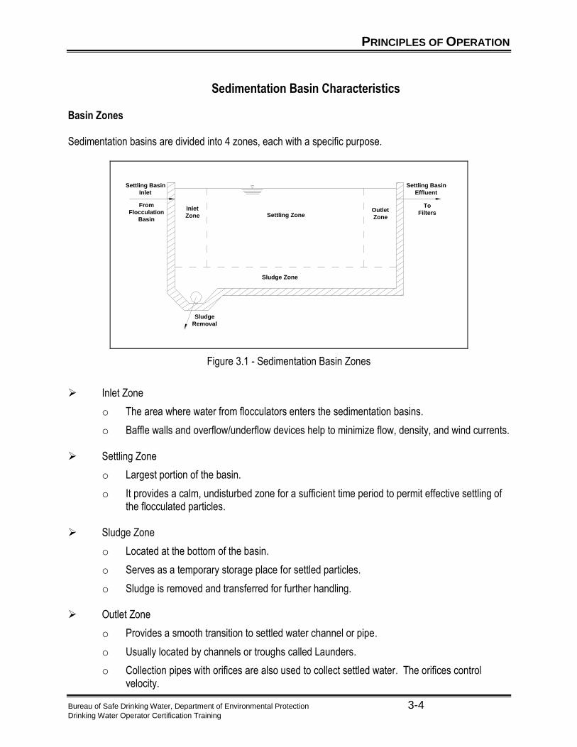
Basin Zones Sedimentation basins are divided into 4 zones, each with a specific purpose.
Settling Zone
Sludge Zone
Inlet
ZoneOutlet
Zone
From
Flocculation
Basin
Settling Basin
Effluent
To
Filters
Sludge
Removal
Settling Basin
Inlet
Figure 3.1 - Sedimentation Basin Zones
Inlet Zone
o The area where water from flocculators enters the sedimentation basins.
o Baffle walls and overflow/underflow devices help to minimize flow, density, and wind currents. Settling Zone
o Largest portion of the basin.
o It provides a calm, undisturbed zone for a sufficient time period to permit effective settling of the flocculated particles.
Sludge Zone
o Located at the bottom of the basin.
o Serves as a temporary storage place for settled particles.
o Sludge is removed and transferred for further handling.
Outlet Zone
o Provides a smooth transition to settled water channel or pipe.
o Usually located by channels or troughs called Launders.
o Collection pipes with orifices are also used to collect settled water. The orifices control velocity.

PRINCIPLES OF OPERATION
Bureau of Safe Drinking Water, Department of Environmental Protection 3-5 Drinking Water Operator Certification Training
Basin Types Rectangular Basin
o Common in large plants.
o High tolerance to changes in water quality.
o Predictable performance.
o Low maintenance.
o Minimal short-circuiting.
o Sludge collection usually with in-line scrappers.
Flat or slightly sloping bottom to sludge collection hopper.
Collection hopper usually at influent end of basin.
Sludge collection devices should move very slowly.
Circular or Square Basins
o Commonly called Clarifiers.
o The usual flow path is center inlet with flow to the edges.
More likely to have short-circuiting problems.
o Sludge collection is usually done with a rotating scraper.
Sloping bottom to central sludge collection hopper.
Scraper can cause currents resulting in solids settling problems.
Sludge can buildup in corners of square units. This is a problem because it can turn septic.
Note: If a sludge collector is not moving but the motor is running, check to see if the shear pin is broken.

PRINCIPLES OF OPERATION
Bureau of Safe Drinking Water, Department of Environmental Protection 3-6 Drinking Water Operator Certification Training
Operating Parameters
Detention Time
Detention Time is the time required for a given molecule of water to move through the basin at a given rate of flow. The average detention time in a sedimentation basin should be 1 to 4 hours.
Theoretical Detention Time Calculated time based on basin volume and rate of flow (Q). Theoretical Detention Time Formula
Volume (gal)
Q (gpm) X 60 (min/hr)DT(t),hrs =
Volume (gal)
Q (gpm) X 60 (min/hr)DT(t),hrs =
Volume (gal)
Q (gpm) X 60 (min/hr)DT(t),hrs =
Actual Detention Time
Actual time based on tracer studies. This is when a chemical is injected into the basin influent and time is measured until 10% of the chemical is noted in the effluent.
Usually different than theoretical detention time due to:
o Short-circuiting
o Inlet and outlet conditions
o Hydraulic currents

PRINCIPLES OF OPERATION
Bureau of Safe Drinking Water, Department of Environmental Protection 3-7 Drinking Water Operator Certification Training
Surface Overflow Rate
Surface Overflow Rate is one of most important factors influencing sedimentation. It is often called Overflow Loading Rate and translates into a velocity which equals the settling velocity of the smallest particle which will be removed. If is simple to remember that loading rates are in gallons per square foot of surface area per unit of time, gpd/sq.ft.
Generally, particles settle downward (in a direction opposite water flow) while water rises in a
sedimentation basin.
o Particles with settling velocities greater than the Overflow Rate will be removed.
o Particles with settling velocities less than the Overflow Rate will be carried through and out of the basin.
The Surface Overflow Rate is also referred to as the Surface Loading Rate. Here is the equation:
Q (gpd)
Surface Area (sq ft)Surface Loading (Vo), gpd/sq ft =
Q (gpm)
Surface Area (sq ft)Surface Loading (Vo), gpm/sq ft =
Or
Q (gpd)
Surface Area (sq ft)Surface Loading (Vo), gpd/sq ft =
Q (gpm)
Surface Area (sq ft)Surface Loading (Vo), gpm/sq ft =
Q (gpd)
Surface Area (sq ft)Surface Loading (Vo), gpd/sq ft =
Q (gpd)
Surface Area (sq ft)Surface Loading (Vo), gpd/sq ft =
Q (gpm)
Surface Area (sq ft)Surface Loading (Vo), gpm/sq ft = Q (gpm)
Surface Area (sq ft)Surface Loading (Vo), gpm/sq ft =
Or
When flow increases through the basin, the surface overflow rate (i.e. surface loading rate) will
increase and the detention time decreases.
PRINCIPLES OF OPERATION
Bureau of Safe Drinking Water, Department of Environmental Protection 3-8 Drinking Water Operator Certification Training
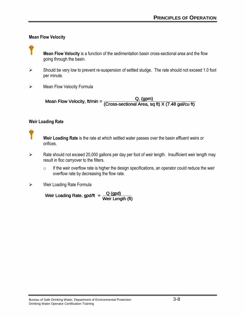
Mean Flow Velocity
Mean Flow Velocity is a function of the sedimentation basin cross-sectional area and the flow going through the basin.
Should be very low to prevent re-suspension of settled sludge. The rate should not exceed 1.0 foot
per minute.
Mean Flow Velocity Formula
Q, (gpm)
(Cross-sectional Area, sq ft) X (7.48 gal/cu ft)Mean Flow Velocity, ft/min =
Q, (gpm)
(Cross-sectional Area, sq ft) X (7.48 gal/cu ft)Mean Flow Velocity, ft/min =
Q, (gpm)
(Cross-sectional Area, sq ft) X (7.48 gal/cu ft)Mean Flow Velocity, ft/min =
Weir Loading Rate
Weir Loading Rate is the rate at which settled water passes over the basin effluent weirs or orifices.
Rate should not exceed 20,000 gallons per day per foot of weir length. Insufficient weir length may
result in floc carryover to the filters.
o If the weir overflow rate is higher the design specifications, an operator could reduce the weir overflow rate by decreasing the flow rate.
Weir Loading Rate Formula
Weir Loading Rate, gpd/ft =Q (gpd)
Weir Length (ft)Weir Loading Rate, gpd/ft =
Q (gpd)
Weir Length (ft)Weir Loading Rate, gpd/ft =
Q (gpd)
Weir Length (ft)
HIGH RATE SEDIMENTATION PROCESSES
Bureau of Safe Drinking Water, Department of Environmental Protection 3-9 Drinking Water Operator Certification Training
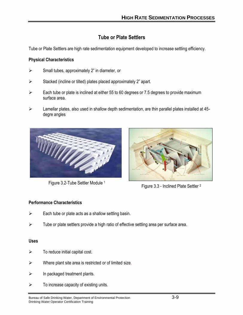
Tube or Plate Settlers Tube or Plate Settlers are high rate sedimentation equipment developed to increase settling efficiency. Physical Characteristics Small tubes, approximately 2” in diameter, or Stacked (incline or tilted) plates placed approximately 2” apart. Each tube or plate is inclined at either 55 to 60 degrees or 7.5 degrees to provide maximum
surface area. Lamellar plates, also used in shallow depth sedimentation, are thin parallel plates installed at 45-
degre angles
Figure 3.2-Tube Settler Module 1 Figure 3.3 - Inclined Plate Settler 2
Performance Characteristics Each tube or plate acts as a shallow settling basin. Tube or plate settlers provide a high ratio of effective settling area per surface area. Uses To reduce initial capital cost.
Where plant site area is restricted or of limited size.
In packaged treatment plants. To increase capacity of existing units.
HIGH RATE SEDIMENTATION PROCESSES
Bureau of Safe Drinking Water, Department of Environmental Protection 3-10 Drinking Water Operator Certification Training
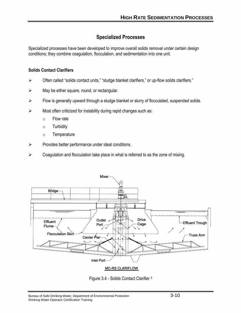
Specialized Processes Specialized processes have been developed to improve overall solids removal under certain design conditions; they combine coagulation, flocculation, and sedimentation into one unit. Solids Contact Clarifiers
Often called “solids contact units,” “sludge blanket clarifiers,” or up-flow solids clarifiers.”
May be either square, round, or rectangular.
Flow is generally upward through a sludge blanket or slurry of flocculated, suspended solids.
Most often criticized for instability during rapid changes such as:
o Flow rate
o Turbidity
o Temperature
Provides better performance under ideal conditions.
Coagulation and flocculation take place in what is referred to as the zone of mixing.
Figure 3.4 - Solids Contact Clarifier 3

HIGH RATE SEDIMENTATION PROCESSES
Bureau of Safe Drinking Water, Department of Environmental Protection 3-11 Drinking Water Operator Certification Training
Ballasted Flocculation/Clarification
Combination of several high-rate processes. Conventional layout – mixing, coagulation, flocculation, and clarification in a single process.
o Sand and polymer added to provide dense particle on which floc can form.
o Tube settlers to reduce required sedimentation area.
o Sand returned to influent for reuse.
Polymer
Sludge
Hydrocyclone
Micro-Sand
Micro-Sand and Sludgeto Hydrocyclone
ClarifiedWater
Tube Clarifierwith Scraper
Maturation
Coagulation
InjectionRawWater
Coagulant
Figure 3.5 Actiflo® Ballasted Flocculation/Clarification System 4
Upflow Contact Clarifier
Flow is passed through a course media bed for removal of floc.
Sludge is removed by backwashing the media bed:
o Based on time or headloss.
o Usually uses raw water for backwash.
Figure 3.6- Upflow Clarifier 5

SEDIMENTATION MATHEMATICAL CALCULATIONS
Bureau of Safe Drinking Water, Department of Environmental Protection 3-12 Drinking Water Operator Certification Training
Theoretical Detention Time
Theoretical Detention Time Calculation Given: A water treatment plant treats a flow of 1.5 mgd. It has 2 sedimentation basins, each 20
feet wide by 60 feet long, with an effective water depth of 12 feet. Problem: Calculate the Theoretical Sedimentation Detention Time with both basins in service. Solution:

SEDIMENTATION MATHEMATICAL CALCULATIONS
Bureau of Safe Drinking Water, Department of Environmental Protection 3-13 Drinking Water Operator Certification Training
Surface Overflow Rate
Surface Overflow Rate Calculation Given: A water treatment plant treats a flow of 1.5 mgd. It has 2 sedimentation basins, each 20
feet wide by 60 feet long, with an effective water depth of 12 feet. Problem: Calculate the Surface Overflow Rate in gallons per minute per square foot of surface area
for the treatment plant with both basins in service. Solution:
SEDIMENTATION MATHEMATICAL CALCULATIONS
Bureau of Safe Drinking Water, Department of Environmental Protection 3-14 Drinking Water Operator Certification Training
Mean Flow Velocity
Mean Flow Velocity Calculation Given: A water treatment plant treats a flow of 1.5 mgd. It has 2 sedimentation basins, each 20
feet wide by 60 feet long, with an effective water depth of 12 feet. Problem: Calculate the Mean Flow Velocity in feet per minute for one of the sedimentation basins,
assuming both basins are in service and there is equal flow distribution to each basin. Solution:
SEDIMENTATION MATHEMATICAL CALCULATIONS
Bureau of Safe Drinking Water, Department of Environmental Protection 3-15 Drinking Water Operator Certification Training
Weir Loading Rate
Weir Loading Rate (Weir Overflow Rate) Calculation
Given: A water treatment plant treats a flow of 1.5 mgd. It has 2 sedimentation basins, each 20 feet wide by 60 feet long, with an effective water depth of 12 feet.
Problem: Calculate the Weir Loading Rate for the treatment plant, assuming there is a single double
sided effluent launder along the width of each basin. Solution:
UNIT 3 EXERCISE
Bureau of Safe Drinking Water, Department of Environmental Protection 3-16 Drinking Water Operator Certification Training
Unit 3 Exercise Word Box
a. Water temperature b. Particle size c. Inlet zone d. Detention time e. Gravitational settling f. Particle shape g. Outlet zone h. Relationship of downward movement of
particle to forward flow velocity i. Rectangular basin j. Circular or Square basin
k. Electrical charge of particle l. Environmental conditions m. Sludge n. Clarifiers o. Surface loading rate p. Sludge zone q. Settling zone r. Mean flow velocity s. Weir overflow rate t. Tube or Plate settlers
Use the Word Box above to complete the following: 1. Identify the four zones of a sedimentation basin. 2. List four operating parameters important to sedimentation. 3. List the settling characteristics upon which the sedimentation process is dependent.
UNIT 3 EXERCISE
Bureau of Safe Drinking Water, Department of Environmental Protection 3-17 Drinking Water Operator Certification Training
Fill in blanks: 4. The ________________ portion of the horizontal flow sedimentation basin is the settling zone. 5. If the motor is normally running and the sludge collector is not moving, the most likely cause of a
clarifier sludge collector problem would be that a ________________ _____________ is broken.
6. A sludge collector device should move very ____________________ . 7. Increase flow to the treatment plant will affect the settling tank in that the detention time will
_____________ and the overflow rate will ________________. 8. A series of thin parallel plates installed at 45-degree angle for shallow depth sedimentation are
known as _______________________ _____________ . 9. Two methods if improving settling efficiency in a sedimentation basins are using tilted plates or
________________________ ______________________.. 10. If the weir overflow rate for a clarifier is too _____________, floc carry over will be observed.
UNIT 3 SUMMARY
Bureau of Safe Drinking Water, Department of Environmental Protection 3-18 Drinking Water Operator Certification Training
Unit 3 Key Points
The largest portion of the horizontal flow sedimentation basin is the settling zone. Conventional sedimentation basins require detention times ranging from 1 to 4 hours. When checking the sedimentation basin immediately before filtration, an operator notices an
extreme amount of floc carryover. The best corrective measure to take is to run a jar test to check chemical dosage and effectiveness.
Sedimentation is improved by uniform low velocity flow across the basin. In a properly designed and operated water treatment plant, the greatest removal of the colloidal
material in raw water should occur during sedimentation. Sedimentation basin loading rates in gallons per square foot of surface area per unit time are
called surface overflow rates. Increased flow to the treatment plant will affect the settling tank in that the detention time will
decrease and the overflow rate will increase. If the weir overflow rate for a clarifier is too high, floc carry over will be observed. A method of improving settling efficiency of shallow rectangular sedimentation basins is by the
addition of a series of plates. Tilted plate settlers are a method used to improve sedimentation and function similar to tube
settlers. A series of thin parallel plates installed at a 45-degree angle for shallow depth sedimentation are
known as lamellar plates. Tube settlers are used to aid sedimentation. A solids-contact basin combines the treatment steps of coagulation, flocculation, and
sedimentation. Coagulation and flocculation in a solids contact basin take place in the zone of mixing. If the motor is running normally and the sludge collector is not moving, the most likely cause of a
clarifier sludge collector problem would be that a shear pin is broken. A sludge collection device should move very slowly.

UNIT 3 REFERENCES
Bureau of Water Supply and Wastewater Management, Department of Environmental Protection 3-19 Drinking Water Operator Certification Training
1 “Tube Settler Module.” http://www.enviropax.com (17 Jun. 2003).
2 “Inclined Plate Settler.” http://www.waterlink.com (17 Jun. 2003).
3 “Solids Contact Clarifier.” http://www.walkerprocess.com (17 Jun. 2003).
4 ”Actiflo® Ballasted Flocculation/Clarification System.” http://www.usfilter.com((17 Jun. 2003). 5 ”Upflow Clarifier.” http://www.usfilter.com (17 Jun. 2003).

Bureau of Water Supply and Wastewater Management, Department of Environmental Protection 4-1 Drinking Water Operator Certification Training
Unit 4 – Filtration
Learning Objectives
Define filtration as it relates to water treatment. Identify the four performance considerations of Filtration.
Given the formula and required data, calculate each of the following: filtration rate and backwash
rate. Explain the importance of good record keeping.
GENERAL OVERVIEW OF CONVENTIONAL FILTRATION
Bureau of Water Supply and Wastewater Management, Department of Environmental Protection 4-2 Drinking Water Operator Certification Training
Process Description
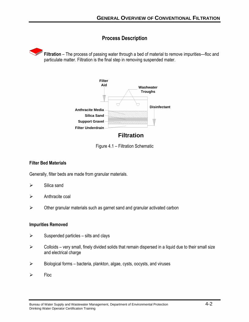
Filtration – The process of passing water through a bed of material to remove impurities—floc and particulate matter. Filtration is the final step in removing suspended mater.
Support Gravel
Filter Underdrain
Silica Sand
Filtration
Filter
Aid
DisinfectantAnthracite Media
Washwater
Troughs
Figure 4.1 – Filtration Schematic
Filter Bed Materials Generally, filter beds are made from granular materials. Silica sand Anthracite coal Other granular materials such as garnet sand and granular activated carbon Impurities Removed Suspended particles – silts and clays Colloids – very small, finely divided solids that remain dispersed in a liquid due to their small size
and electrical charge Biological forms – bacteria, plankton, algae, cysts, oocysts, and viruses Floc
GENERAL OVERVIEW OF CONVENTIONAL FILTRATION
Bureau of Water Supply and Wastewater Management, Department of Environmental Protection 4-3 Drinking Water Operator Certification Training
Filtration Mechanisms
Physical and Chemical Process Based upon:
Chemical characteristics of the water
Nature of suspended material
Types and degree of pretreatment
Filter type and operation Removal Processes
Sedimentation on media.
Adsorption – The collection of a gas, liquid or dissolved substance on the surface and interface zone of another material.
Biological action.
Absorption – The taking in or soaking up of one substance into the body of another by molecular or chemical action (e.g., tree roots absorb dissolved nutrients in the soil).
Straining – The removal of particulates by trapping in the open spaces between the grains of the media.
TYPES OF FILTERS
Bureau of Water Supply and Wastewater Management, Department of Environmental Protection 4-4 Drinking Water Operator Certification Training
Gravity Filters
Gravity Filters – Water moves downward through filter media by gravity. Slow Rate Gravity Filtration (Covered in Module 17) Low filtration rates:
o 45 to 150 gpd/sqft (0.03 to 0.10 gpm/sqft).
Majority of material removed in top several inches of media.
Cleaned by removing and replacing top media layer.
Limited application due to area requirements and manual cleaning.
Filter media – 24” to 30” deep silica sand bed.
Rapid Rate Gravity Filtration Filtration rate is dependent on the media used.
o Single media = 2 gpm/sqft
o Dual or Multi media = 4 gpm/sqft
o Higher rates permitted if justified based on raw water quality, degree of pretreatment, media type, and other factors.
Filter media can be single, dual or multi.
o Single media bed is 24” to 30” deep, and made up of:
Clean silica sand, or
Clean, crushed anthracite coal.
o Dual media bed is 24” to 30” deep containing both sand and anthracite:
Silica sand, 9” to 12” deep, and
Crushed anthracite 15” to 18” deep.
o Multi or mixed media bed is 24” to 30” deep containing silica sand, anthracite coal, and a layer of dense, small grained garnet sand:
Garnet Sand - 3” layer,
Silica Sand - 9” to 12” layer, and
Anthracite - 15” to 18” layer.
TYPES OF FILTERS
Bureau of Water Supply and Wastewater Management, Department of Environmental Protection 4-5 Drinking Water Operator Certification Training
Pressure Filters
Pressure Filters – Water is forced through the media under pressure. Pressure Filtration This is simply the conventional filtration process under pressure. Precoat Filtration (Diatomaceous Earth) (Covered in Module 16) Media is added to water being treated prior to the water entering the filter. Media collects on porous screening device. Media coating thickness increases during filter run as more media is added. Media is wasted during backwash process. Swimming pool filter is good example. Cartridge or Bag Filtration (Covered in Module 18) Uses replaceable cartridge or bag filters.
FILTER CONTROL SYSTEMS
Bureau of Water Supply and Wastewater Management, Department of Environmental Protection 4-6 Drinking Water Operator Certification Training
Filter control systems regulate flow rates by maintaining adequate head above the media surface. This prevents sudden flow increases, or surges, which could dislodge trapped solids.
Common Filter Control Systems Constant Rate
Each filter is equipped with a rate-of-flow control valve.
The valve maintains a constant rate of water flow through the filter.
As filter clogs the valve slowly opens to maintain the flow rate.
Declining Rate
The filter controller maintains a constant level of water above the media.
Filtration rate declines as filter clogs.
A loss of head gauge on a filter us used to measure the drop in pressure through a filter bed.
If the water in a filter bed is drawn below the filter surface and more water is applied, air binding of a filter bed may occur.
o Air binding prevents uniform filtration through all parts of the filter.
PERFORMANCE CONSIDERATIONS
Bureau of Water Supply and Wastewater Management, Department of Environmental Protection 4-7 Drinking Water Operator Certification Training
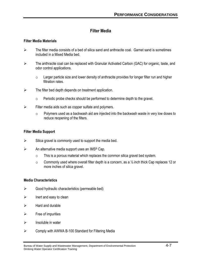
Filter Media
Filter Media Materials The filter media consists of a bed of silica sand and anthracite coal. Garnet sand is sometimes
included in a Mixed Media bed. The anthracite coal can be replaced with Granular Activated Carbon (GAC) for organic, taste, and
odor control applications.
o Larger particle size and lower density of anthracite provides for longer filter run and higher filtration rates.
The filter bed depth depends on treatment application.
o Periodic probe checks should be performed to determine depth to the gravel.
Filter media aids such as copper sulfate and polymers.
o Polymers used as a backwash aid are injected into the backwash waste in very low doses to reduce reopening of the filters.
Filter Media Support Silica gravel is commonly used to support the media bed.
An alternative media support uses an IMS® Cap.
o This is a porous material which replaces the common silica gravel bed system.
o Commonly used where overall filter depth is a concern, as a ½ inch thick Cap replaces 12 or more inches of silica gravel.
Media Characteristics
Good hydraulic characteristics (permeable bed)
Inert and easy to clean
Hard and durable
Free of impurities
Insoluble in water
Comply with AWWA B-100 Standard for Filtering Media
PERFORMANCE CONSIDERATIONS
Bureau of Water Supply and Wastewater Management, Department of Environmental Protection 4-8 Drinking Water Operator Certification Training
Media Classification
Effective Size (ES)
o Size of sieve opening which permits 10 percent of media particles (by weight) to pass.
o Some operational problems are improved by proper selection of media effective size:
Time required for turbidity breakthrough.
Time required for filter to reach limiting or terminal headloss.
Uniformity Coefficient (UC)
Referred to as the measure of uniformity of filter media.
o UC is a ratio based on sieve size.
o UC is equal to the size of the sieve opening that will just pass 60 percent (by weight) of a representative sample of the media, divided by the size of the sieve opening that will just pass 10 percent (by weight) of the same sample.
o Formula: UC = D60 D10
o Media with lower UC is more uniform in size than media with higher UC. Generally, the lower the UC, the slower the headloss buildup
Specific Gravity (SG)
o Ratio of the unit weight of the media to that of water
Hardness
o Resistance to erosion or wearing away of the particle
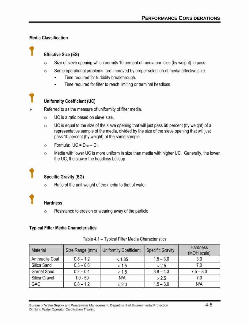
Typical Filter Media Characteristics
Table 4.1 – Typical Filter Media Characteristics
Material Size Range (mm) Uniformity Coefficient Specific Gravity Hardness
(MOH scale)
Anthracite Coal 0.8 – 1.2 1.85 1.5 – 3.0 3.0
Silica Sand 0.3 – 0.6 1.5 2.5 7.0
Garnet Sand 0.2 – 0.4 1.5 3.8 – 4.3 7.5 – 8.0
Silica Gravel 1.0 - 50 N/A 2.5 7.0
GAC 0.8 – 1.2 2.0 1.5 – 3.0 N/A
PERFORMANCE CONSIDERATIONS
Bureau of Water Supply and Wastewater Management, Department of Environmental Protection 4-9 Drinking Water Operator Certification Training
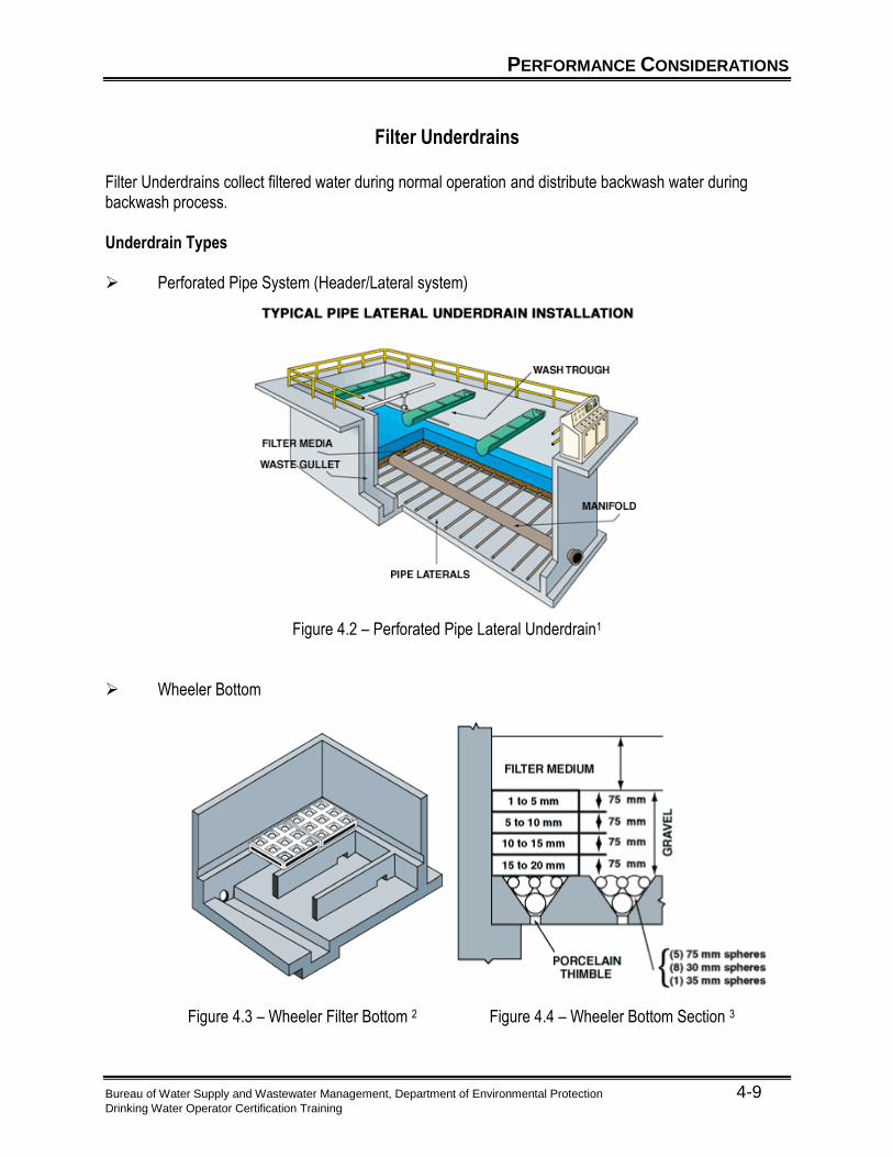
Filter Underdrains
Filter Underdrains collect filtered water during normal operation and distribute backwash water during backwash process. Underdrain Types Perforated Pipe System (Header/Lateral system)
Figure 4.2 – Perforated Pipe Lateral Underdrain1 Wheeler Bottom
Figure 4.3 – Wheeler Filter Bottom 2 Figure 4.4 – Wheeler Bottom Section 3
PERFORMANCE CONSIDERATIONS
Bureau of Water Supply and Wastewater Management, Department of Environmental Protection 4-10 Drinking Water Operator Certification Training
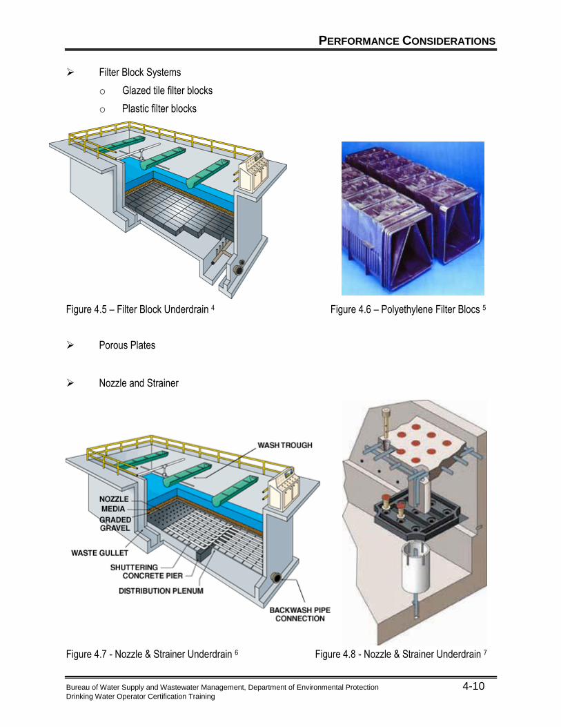
Filter Block Systems
o Glazed tile filter blocks
o Plastic filter blocks
Figure 4.5 – Filter Block Underdrain 4 Figure 4.6 – Polyethylene Filter Blocs 5
Porous Plates Nozzle and Strainer
Figure 4.7 - Nozzle & Strainer Underdrain 6 Figure 4.8 - Nozzle & Strainer Underdrain 7
PERFORMANCE CONSIDERATIONS
Bureau of Water Supply and Wastewater Management, Department of Environmental Protection 4-11 Drinking Water Operator Certification Training
Filter Operating Parameters
Filter Production – The difference between the total water produced and the backwash water used. Filter capacity is recorded in million gallons per day.
Filtration Rate – The flow of water through the filter in gallons per minute per square foot of filter area
Filtration Efficiency – The measure of overall plant reduction in turbidity.
Filtration efficiency is dependent upon:
o Quality of water being treated.
o Effectiveness of pretreatment.
o Filter operation.
Effectiveness of pretreatment processes in conditioning water for filtration is the single most important aspect to good filtration efficiency.
PERFORMANCE CONSIDERATIONS
Bureau of Water Supply and Wastewater Management, Department of Environmental Protection 4-12 Drinking Water Operator Certification Training
Backwashing
Backwashing – The process of reversing the flow of water back through the filter media to remove the trapped material.
Purpose Required to remove material trapped by media.
o Too low of a backwash rate will not completely remove trapped solids.
o Too high of a rate may cause excessive loss of media and media disturbance (mounding).
Effluent turbidity monitoring will indicate need for backwashing.
Processes Media is expanded or fluidized by reversing water flow.
o Pressurized water supply required:
Backwash pump.
Elevated backwash water storage tank.
o Potable quality water (filtered water) is used for backwash supply.
Normally uses 2 to 5 percent of the treated water produced.
o Entrapped solids are washed away for further processing in the residual waste handling system.
Surface wash or air scour is used to enhance cleaning by loosening entrapped material so that it
can be carried away by the backwash water. Filter rinse is the initial period of filtering to waste while the filtered water turbidity returns to the
normal level. A Secchi disk is used to determine bed expansion during backwash.
In rapid sand filtration, a pressure filter must be run in filter-to-waste mode after backwashing. Typical Backwash Rates Low Wash: 3 – 8 gpm/sq ft of filter area High Wash: 15 – 20 gpm/sq ft of filter area Air Scour: 3 – 5 scfm/sq ft of filter area Surface Wash: 0.5 – 2.0 gpm/sq ft of filter area

UNIT 4 EXERCISE
Bureau of Water Supply and Wastewater Management, Department of Environmental Protection 4-13 Drinking Water Operator Certification Training
Unit 4 Exercise 1 – 4. There are four performance considerations of Filtration listed below. Match each consideration with
the correct explanation of that consideration.
Performance Consideration Explanation
1. Filter Media
Filter production and efficiency
2. Filter Underdrains
The materials used to filter out impurities
3. Filter Operating Parameters
The process of reversing the flow of water back through the filter media to remove trapped material.
4. Backwashing
Where filtered water is collected during normal operation.
5. Write your own definition of filtration below.
6. What are the reasons for keeping good records?

PROCESS CALCULATIONS
Bureau of Water Supply and Wastewater Management, Department of Environmental Protection 4-14 Drinking Water Operator Certification Training
Filtration Rate
Filtration rate – The flow which is filtered by one (1) square foot of filter surface area. It is determined by dividing the flowrate through the filter, in gallons per minute, by the filter surface area, in square feet.
Filtration Rate Sample Calculation Given: A plant has four filters, each 22 feet wide by 25 feet long. When in operation, the plant
treats a total flow of 10 million gallons per day. Problem: Calculate the filtration rate. Solution: Step 1
Q, gpm = (Q, mgd x 1,000,000) [(24 hr/day x 60 min/hr)]
= (10 x 1,000,000) (24 x 60) = 6945 gpm
Step 2
Q/filter, gpm = 6945 gpm 4 filters = 1736 gpm/filter
Step 3
A, sq ft = 22 ft wide x 25 ft long = 550 sq ft
Step 4
Filtration Rate gpm/sq ft = Q/filter, gpm A, sq ft
= 1736 gpm 550 sq ft = 3.16 gpm/sq ft

PROCESS CALCULATIONS
Bureau of Water Supply and Wastewater Management, Department of Environmental Protection 4-15 Drinking Water Operator Certification Training
Filtration Rate Calculation
Given: A plant has four filters, each 22 feet wide by 25 feet long. When in operation, the plant treats a total flow of 10 million gallons per day. The water level drops 2 feet in 5 minutes with the influent valve closed.
Problem: Compute the filtration rate.
Solution:
PROCESS CALCULATIONS
Bureau of Water Supply and Wastewater Management, Department of Environmental Protection 4-16 Drinking Water Operator Certification Training
Backwash Rate
Backwash Rate is the flow rate at which the filter is backwashed. The Backwash Rate is usually expressed in gallons per minute per square foot of filter surface area, or the backwash pumping rate in gallons per minute. May be expressed as a rise rate in inches per minute. Formulas involving backwash calculations are similar to formulas for computing filtration rates. Backwash Rate Sample Calculation
Given: A filter 26 feet wide by 30 feet long with the desired backwash rate of 18 gallons per minute per square foot.
Problem: Determine the required backwash pumping rate. Solution: Step 1
A, sq ft = (length, ft) x (width, ft)
= (30 x 26)
= 780 sq ft
Step 2
Backwash Pumping Rate, gpm = Filter Area, sq ft x Backwash rate, gpm/sq ft
= 780 sq ft x 18 gpm/sq ft
= 14,040 gpm

PROCESS CALCULATIONS
Bureau of Water Supply and Wastewater Management, Department of Environmental Protection 4-17 Drinking Water Operator Certification Training
Backwash Rate Calculation #1
Given: A filter 26 feet wide by 30 feet long with the desired backwash rate of 18 gallons per minute per square foot (same as for Sample #1)
Problem: Determine the volume of water in gallons required to backwash the filter in Sample #1, if
the filter is backwashed for 10 minutes. Solution:
PROCESS CALCULATIONS
Bureau of Water Supply and Wastewater Management, Department of Environmental Protection 4-18 Drinking Water Operator Certification Training
Backwash Rate Calculation #2
Given: A filter 18 feet wide by 20 feet long with a backwash rate of 20 gallons per minute per square foot.
Problem: Determine the backwash rise rate in inches per minute Solution:
RECORD KEEPING
Bureau of Water Supply and Wastewater Management, Department of Environmental Protection 4-19 Drinking Water Operator Certification Training
Daily Logs
Plant operators maintain a daily log of process performance data and water quality characteristics. Various performance records are required by regulatory agencies and these logs contain the necessary information. Good historical operational records can also serve as a guide to current plant performance and process changes necessary to improve finished water quality. Logs are Accurate Records of: Process water quality
o Turbidity
o Color
Process operation
o Filters in service
o Filtration rates
o Loss of head
o Length of filter runs
o Frequency of backwash
o Backwash rates
Process water production Percent of water production used to backwash filters and other plant uses (laboratory samples,
mixing chemicals, washdown, etc.) Process equipment performance
o Types and number of equipment in operation
o Equipment adjustments made
o Maintenance performed
o Equipment calibration
Log Entries Should: Be neat and legible Reflect time and date of an event Be initialed by operator making entry
UNIT 4 SUMMARY
Bureau of Water Supply and Wastewater Management, Department of Environmental Protection 4-20 Drinking Water Operator Certification Training
Unit 4 Key Points
In conventional water treatment, the final step in the removal of suspended matter is filtration. In a filter using anthracite and sand, the anthracite should be located as the top layer of media. The indicator used to monitor the mixed media filtration process is turbidity. The term “uniformity coefficient” refers to the measure of uniformity of filter media size. The maintenance of a filter bed involves a periodic probe check to determine depth to the gravel. Copper sulfate is a good filter aid. Polymers used as filter aids work to improve filter performance because they strengthen bonds
between particles and coat filter media to improve adsorption. Loss of head in a filter represents the resistance to flow as it passes through the filter media. If the water in a filter bed is drawn below the filter surface and more water is applied, air binding of
the filter bed may occur. Air binding a filter prevents uniform filtration through all parts of the filter bed. A loss of head gauge on a filter is used to measure the drop in pressure through the filter bed. The purpose of the rate-of-flow controller on the effluent piping of a filter is to control the rate of
filtration. Larger particle size and lower density of anthracite filter media provides for longer filter run, higher
filtration rates. Before placing a rapid sand filter into service, the filter should be backwashed. A filter needs backwashing when the operator observes excessive effluent turbidity. Filtered water is always used for backwashing to avoid contamination of the filter bed. After backwashing a filter, you should filter to waste and check turbidity. A Secchi disk is used to determine bed expansion during backwash. Polymers used as backwash aids are injected into the backwash water in very low doses to reduce
the ripening time of filters.
UNIT 4 REFERENCES
Bureau of Water Supply and Wastewater Management, Department of Environmental Protection 4-21 Drinking Water Operator Certification Training
1 “Perforated Pipe Lateral Underdrain.” http://www.fbleopold.com (17 Jun. 2003).
2 “Wheeler Filter Bottom.” http://www.fbleopold.com (17 Jun. 2003). 3 “Wheeler Bottom Section.” http://www.fbleopold.com (17 Jun. 2003). 4 “Filter Block Underdrain.” http://www.fbleopold.com (17 Jun. 2003). 5 “Polyethylene Filter Blocs.” http://www.robertsfiltergroup.com (17 Jun. 2003). 6 “Nozzle & Strainer Underdrain.” http://www.fbleopold.com (17 Jun. 2003). 7 “Nozzle & Strainer Underdrain.” http://www.usfilter.com (17 Jun. 2003).

Bureau of Water Supply and Wastewater Management, Department of Environmental Protection 5-1 Drinking Water Operator Certification Training
Unit 5 – Operation of Conventional Filtration Facilities
Learning Objectives
Identify the five components of Normal Operations.
Explain the importance of “jar testing” and describe how the test is performed.

NORMAL OPERATION
Bureau of Water Supply and Wastewater Management, Department of Environmental Protection 5-2 Drinking Water Operator Certification Training
Process Performance Monitoring
Overview Monitoring process performance is an ongoing, regular activity of plant operators. Early detection of a pre-treatment failure is extremely important to effective filtration performance. Keep accurate plant operation records. They:
o Serve as a guide to help solve current or future process related operational problems.
o Provide a running account of plant operations.
o Are required by regulatory agencies.
o Should be neat, legible, and easily found.
o Should contain the date and time of an event and be initialed by the operator making the entry for future reference.
o Should include plots of key process variables (i.e., raw water turbidity vs. coagulant dosage).
Early detection of a potential problem may allow for process modifications to correct a problem, limit the severity, or maybe even prevent the problem altogether. Don’t wait for customer complaints as an indication of problems in filtration and backwashing.
Monitoring Methods Continuous water quality analyzers for continually measuring various process variables:
o Turbidity
o Temperature
o pH
o Streaming current
Visual observations of:
o Mixing turbulence
Floc quantity and quality.
Water flow patterns indicating short circuiting.
Buildup of foreign material such as leaves, twigs, other debris.
o Turbidity
Upon entering and leaving sedimentation basin.
Indication of floc or solids loading on sedimentation process.
Difference reveals effectiveness or efficiency of process.
NORMAL OPERATION
Bureau of Water Supply and Wastewater Management, Department of Environmental Protection 5-3 Drinking Water Operator Certification Training
Low sedimentation process effluent turbidity is desirable as it minimizes the filter load.
o Temperature
Water temperature very important.
Affects settling rate.
Colder water = Slower settling.
Temperature changes usually gradual.
Dependent on time of year and weather.
o Floc settling characteristics such as:
Flock size and density.
Floc settling rate.
Floc carryover to filters.
Monitor Filtration Process Filter influent turbidity or, settled water turbidity.
o Check on periodic basis
Continuous sample or grab sample.
Frequency dependent on raw water quality and pretreatment operations.
Minimum 1X per shift.
More frequently is better.
Filter effluent turbidity or filtered water turbidity.
o Continuous monitoring with on-line turbidimeter
Provides continuous feedback on filter performance.
Headloss - measures solids accumulation in the filter bed. It is the resistance to flow as it passes through a filter.
o Actual filter head loss
Good indication of how well the filter is performing.
Indication that backwash is required.
o Rate of increase
Should be constant increase.
Sudden increase indicates potential problem such as surface sealing.
o Anionic polymers are one chemical that could increase head loss on the filters.
o An malfunctioning differential pressure gauge will display an incorrect head loss.

NORMAL OPERATION
Bureau of Water Supply and Wastewater Management, Department of Environmental Protection 5-4 Drinking Water Operator Certification Training
Process Controls and Equipment
Check and Adjust Process Controls and Equipment Calibration of analytical instruments. Coagulation/flocculation process:
o Check and adjust flash mixer and flocculator speed controls.
o Chemical feeders:
Check chemical feed rate.
Check feeder accuracy.
o Make pretreatment modifications as necessary.
Sedimentation process:
o Operate sludge removal equipment.
Filtration process:
o Add and remove filters from operation as required by water demands.
o Change filtration rate.
o Backwash filters.
Determine need for backwashing on the basis of filter headloss, time in service, or turbidity breakthrough.
Headloss is generally limited to a maximum 7 feet.
Wash every 48 to 72 hours regardless of filter headloss.
Wash prior to filter effluent turbidity exceeding established Maximum Contaminant Level (MCL).
Record filter run length, effluent turbidity, and headloss since last backwash.
Close filter influent valve.
Open drain valve.
Close effluent valve.
Start surface wash or air scour system.
Start water backwash at low wash rate.
Stop surface wash or air scour system.
Increase backwash rate to high rate to fluidize media bed at proper time.
Observe backwash for:
Backwash water clarity near end of wash cycle.
“Boils” or uneven distribution of flow.
Media carry-over into backwash troughs.
Wash at high wash rate until filter is clean.
NORMAL OPERATION
Bureau of Water Supply and Wastewater Management, Department of Environmental Protection 5-5 Drinking Water Operator Certification Training
Decrease backwash rate to low rate to restratify filter bed.
Stop water backwash.
Close drain valve.
Open rinse valve.
Open influent valve and rinse filter until effluent turbidity levels return to normal.
Close rinse valve and open effluent valve.
Return filter to normal service.
Observe condition of media surface.
Record length of wash, rinse, and water usage.
Evaluate filter media condition.
o Examine filter media at least annually:
Measure media level to determine media loss during backwashing.
Monitor for mud ball accumulation in media to evaluate backwash effectiveness.
Observe for signs of surface cracking or cracks along the filter wall.
o If the filter media is replaced, the best way to disinfect a filter is use enough chlorine so that a significant residual remains after 24-hours.
Process Support Equipment Plant operators must operate and maintain the following support equipment in accordance with manufacturer’s recommendations:
Filter control valves
Backwash and surface wash pumps
Air scour blowers
Flow meters and level/pressure gauges
o Isolate and depressurize the line before removing and cleaning a primary in-line raw water meter.
Water quality monitoring equipment (turbidimeters)
o A 4-20mA control signal is typically used for an output signal from the turbidity meter to chart recorder, flow meter signal, and the output signal from chlorine analyzer.
Process monitoring equipment (head loss and filter level)
Mechanical and electrical filter control systems
Sludge drying: Sludge drying beds and sludge filter presses
o Reduce the volume of sludge that must be handled or disposed.

NORMAL OPERATION
Bureau of Water Supply and Wastewater Management, Department of Environmental Protection 5-6 Drinking Water Operator Certification Training
Housekeeping
Plant operators must perform routine housekeeping chores and keep the area clean and free of debris. Several items of routine maintenance and housekeeping that are common to all facilities include: Painting Routine repainting of equipment and other plant facilities both improves appearance and extends useful life.
Equipment Maintenance
Routine equipment maintenance includes:
Check lubrication,
Clean,
Check for proper operation, and
Adjust as necessary.
General Plant and Yard Work
Cleaning and sweeping.
Mowing lawn areas.
Cleaning up chemical spills.

NORMAL OPERATION
Bureau of Water Supply and Wastewater Management, Department of Environmental Protection 5-7 Drinking Water Operator Certification Training
Laboratory Testing
Perform Required Laboratory Testing Perform on a routine basis.
o Frequency of testing depends on source water.
Water quality from lake and reservoir supplies are generally less variable than stream or river supplies so these sources may require less frequent testing.
Direct diversions from streams and rivers are usually more variable, and, therefore, require source quality changes more rapidly.
o Most commonly tested for turbidity, alkalinity, pH, color, temperature, and chlorine demand.
o Other common tests include iron, manganese, nitrates depending on source type and normal raw water quality.
Evaluate water quality - both raw and treated.
o Compare raw water quality test results with historical records.
o Compare treated water quality with historical records and MCL limits.
Jar Testing
While it is almost impossible to duplicate actual plant conditions, Jar Testing is used to verify process performance. It attempts to duplicate in the laboratory what is occurring in the plant in relation to detention times, mixing conditions, and settling conditions and should be used as a method to forecast plant process performance.
o Plant operating conditions should closely approximate jar test results at the best coagulant dose.
o Routine performance of Jar Tests provides additional information to help make required adjustments to actual plant chemical feed rates.
Figure 5.1 Jar Test Stirrer Equipment
NORMAL OPERATION
Bureau of Water Supply and Wastewater Management, Department of Environmental Protection 5-8 Drinking Water Operator Certification Training
Jar Test Procedure
Preparation for test:
Jar test apparatus – “Gang Stirrer.”
Prepare fresh chemicals.
Use test data sheets.
Establish dosage range.
Compare raw water quality with past records and experience.
Bracket expected “best” dosage (i.e., if 15 mg/l of alum is expected to be best, test 5, 10, 15, 20, 25, and 30 mg/l).
Establish test sequence.
Determine testing required – What combinations of coagulants and coagulant aids will be tested?
Change only one variable (i.e., alum dosage only) during each test run.
Any noted changes in test results are then due to the change in that single variable.
Perform multiple runs if multiple variable changes are necessary.
Perform Jar Test
Collect raw water samples.
Temperature of sample being tested should be approximately the same as the water being treated.
Add chemicals as quickly as possible.
Lower stirring paddles and operate at high speed for a minimum of 15 seconds to represent flash mixing.
Reduce speed to represent flocculation basin conditions and mix for a period equivalent to the flocculation basin detention time.
Record time required for visible floc formation and describe floc characteristics (i.e., pinhead size floc, flake size floc, etc.).
Stop stirrers and allow floc to settle for a period equivalent to the sedimentation basin surface loading rate (settling velocity).
Measure turbidity at regular intervals and plot turbidity vs. time curve.
Observe and note floc settling characteristics, floc appearance, and clarity of settled water above floc.
Measure turbidity of settled water.
Plot Turbidity vs. chemical dosage curve.
Note that over dosage usually results in a turbidity increase.

NORMAL OPERATION
Bureau of Water Supply and Wastewater Management, Department of Environmental Protection 5-9 Drinking Water Operator Certification Training
Evaluate Jar Test Results
Rate of floc formation.
Floc formation should begin shortly after “flash mixing.”
Floc should gradually clump together during flocculation mixing.
Type of floc.
Discrete, dense floc particles are usually better than light, fluffy floc and are less subject to shearing (breaking up of the floc).
Large, light floc does not settle as well as smaller, denser floc and is subject to shearing - breaking up the floc.
Amount of sludge is another consideration.
It is desirable to have smaller amounts of sludge. This reduces sludge handling and disposal requirements.
Most sludge volume is the precipitates of the added chemicals rather than suspended solids removed.
Clarity of settled water.
Quantity of floc is not as critical as quality or clarity of settled water.
Hazy water indicates poor coagulation.
Properly coagulated water contains floc particles that are well formed with clear water between the floc.
Floc settling rate.
The rate at which floc settles after mixer is stopped is important.
Floc should start to settle as soon as mixing stops and should be almost complete after 15 minutes.
Floc remaining suspended longer than 15 to 20 minutes is not likely to settle in the plant sedimentation basin and will increase load on the filter.

START-UP AND SHUTDOWN PROCEDURES
Bureau of Water Supply and Wastewater Management, Department of Environmental Protection 5-10 Drinking Water Operator Certification Training
Startup and shutdown procedures are not a routine operating procedure. Generally it is required when facilities are shut down for maintenance.
Start-up Procedures
General Start-up Procedures Check the condition of all mechanical equipment for proper lubrication and operational status. Prepare chemicals. Collect raw water sample and run jar tests. Determine chemical feeder settings and adjust feed rates. Start raw water flow.
o DO NOT allow any untreated water to go through the plant.
All raw water must be treated with coagulant.
Untreated water can pass through filters without proper removal of color and particulates.
Coagulation/Flocculation Equipment Start-up Procedures Start chemical feeders following manufacturer’s recommendations. Start mechanical flash mixers following manufacturer’s instructions.
o May need to wait until tank or channel is full.
Start sample pumps following manufacturer’s recommendations.
o Allow sufficient flushing time before collecting samples.
Start flocculators following manufacturer’s recommendations.
o Observe floc formation and make any necessary changes to the coagulation/flocculation equipment, including chemical feeders, flash mixers, and flocculators.
Perform water quality analyses and make process adjustments and required.
START-UP AND SHUTDOWN PROCEDURES
Bureau of Water Supply and Wastewater Management, Department of Environmental Protection 5-11 Drinking Water Operator Certification Training
Sedimentation Equipment Start-up Procedures Check equipment operational status and mode of operation (manual or automatic). Make sure that:
o Basin drain valves are closed.
o Basin isolation gates or stop logs have been removed.
o Weir plates have been laundered, level has been set, and plates are at proper elevation.
o All trash, debris and tools are removed from basin.
Test sludge removal equipment operation. Make sure that:
o Equipment is properly lubricated and ready for operation.
o Sludge removal equipment is started following manufacturer’s instructions.
o Equipment operation is observed.
Fill basin to:
o Proper water depth, and
o Remove floating debris from water surface.
Start sample pumps following manufacturer’s instructions. Perform water quality analyses and make process adjustments as required. Operate sludge removal equipment. Filters Start-up Procedures Backwash filter. Start filter and filter initial flow to waste. Once turbidity is acceptable (less than 0.3 NTU or one-half of raw water turbidity value):
o Close filter to waste valve, and
o Open filter effluent valve.
Monitor filter performance.
START-UP AND SHUTDOWN PROCEDURES
Bureau of Water Supply and Wastewater Management, Department of Environmental Protection 5-12 Drinking Water Operator Certification Training
Shutdown Procedures
General Shutdown Procedures Shut off raw water flow. Turn off chemical feeders and clean or flush feed lines as necessary. Shut down flash mixer and flocculators as water leaves each process following manufacturer’s
instructions. Shut down sample pumps as water leaves sampling location. Waste all water that has not been properly treated. Lock out and tag appropriate electrical switches. Coagulation/Flocculation/Sedimentation Shutdown Procedures Stop flow to basin.
o Close valves.
o Install gates or stop logs.
Turn off sample pumps. Turn off sludge removal equipment.
o Shut off and disconnect where appropriate.
o Check valves for proper position (open or closed).
Lockout and tag electrical switches and equipment. Drain basin if necessary.
o Be sure water table is not high enough to float the empty basin.
o Open drain valves.
Immediately following dewatering, grease and lubricate all gears, sprockets, and mechanical moving parts which have been submerged.
o Can freeze up (seize up) in a few hours.
o Avoids repairs and equipment breakage.
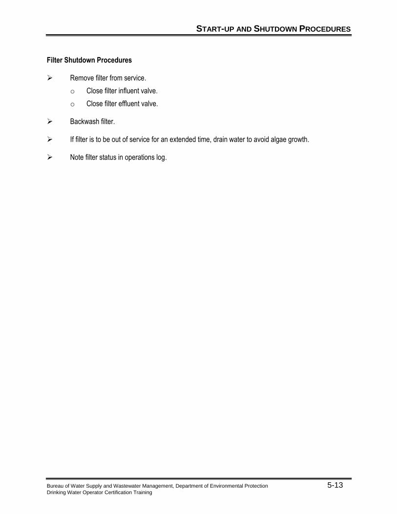
START-UP AND SHUTDOWN PROCEDURES
Bureau of Water Supply and Wastewater Management, Department of Environmental Protection 5-13 Drinking Water Operator Certification Training
Filter Shutdown Procedures Remove filter from service.
o Close filter influent valve.
o Close filter effluent valve.
Backwash filter. If filter is to be out of service for an extended time, drain water to avoid algae growth. Note filter status in operations log.

ABNORMAL OPERATION
Bureau of Water Supply and Wastewater Management, Department of Environmental Protection 5-14 Drinking Water Operator Certification Training
Sudden changes in source or filtered water turbidity, pH, alkalinity, temperature, chlorine demand of source water, or color are signals that the plant operator should immediately review the performance of the coagulation/flocculation process and the sedimentation process.
Changes in Source Water Quality
Increases or decreases in source water turbidity, alkalinity, pH, or temperature can affect floc formation. Plant Operators need to: Verify effectiveness of chemical addition through visual observations and jar testing.
o Jar Test indicating higher dosages are required may mean:
Increased pH adjustment chemical (alkalinity) dosages may be required.
Increased operation of sludge removal equipment may be necessary.
o Temperature changes may require an adjustment to mixing intensity in flash mix or flocculators.
Floc carry-over causes problems in the filtration as the water temperature drops.
Check filter efficiency.
o Compare filter influent turbidity with filter effluent turbidity to determine filter removal efficiency.
o Compare data with recent records.
o Remember, coagulation, flocculation, and sedimentation determine filtration performance.
Increased Filtered Water Turbidity
Sudden increases in filtered water turbidity could be caused by poor filter performance, indicating a need for backwash and or media replacement. Poor coagulation/flocculation performance is usually the cause. Plant operators need to: Watch for rapid changes in headloss or filtered water turbidity during normal filter operation.
o Both indicate an upset or failure in the filtration process or pretreatment processes.

ABNORMAL OPERATION
Bureau of Water Supply and Wastewater Management, Department of Environmental Protection 5-15 Drinking Water Operator Certification Training
Watch for other indicators of abnormal conditions.
o Mud balls, media cracking or shrinkage.
Possible causes are ineffective or improper backwashing.
o Excessive media loss, visible disturbance, or media boils during backwash.
Possible causes include improper backwash rates and filter underdrain failure.
o Short filter runs indicated by: mud ball formation, clogging of the underdrain system, and air binding of filter.
Possible causes include: increased solids loading, filter aid overdosing, and filtration rates too high.
Mud balls in a filter may cause a decrease filter area.
o Algae on the media and filter box walls.
Growth of algae in natural bodies of water is most successfully control by adding copper sulfate.
Record Keeping
Good record keeping is necessary especially during periods of abnormal operation. They provide an historical account of actions taken and may be helpful from a legal or regulatory perspective. “Good records” require plant operators to: Document unique conditions for future reference. Document actions taken to correct the condition.

CONVENTIONAL FILTRATION PROCESS TROUBLESHOOTING
Bureau of Water Supply and Wastewater Management, Department of Environmental Protection 5-16 Drinking Water Operator Certification Training
Conventional Filtration Process Troubleshooting Table Source Water Quality
Table 5.1 Source Water Quality Trouble Shooting Table
Source Water Quality Changes
Identified Problem Operator Actions Possible Process Changes
o Turbidity
o Temperature
o Alkalinity
o pH
o Color
o Chlorine Demand
o Perform necessary analysis to determine extent of change
o Evaluate overall process performance
o Perform Jar Tests
o Make appropriate process changes
o Increase monitoring frequency
o Verify response to process changes
o Adjust coagulant dose
o Change coagulant(s)
o Adjust flash mixer intensity (if possible)
o Adjust Flocculator mixing intensity
o Adjust alkalinity or pH
o Add coagulant aid or filter aid polymer
Conventional Filtration Process Troubleshooting Table Process Quality—Coagulation/Flocculation
Table 5.2 Coagulation/Flocculation Trouble Shooting Table
Coagulation/Flocculation Process Changes
Identified Problem Operator Actions Possible Process Changes
o Turbidity
o Alkalinity
o PH
o Color
o Floc Formation
o Evaluate source water quality
o Evaluate overall performance
o Perform Jar tests
o Observe floc
Dispersion
Size
Settling Rate
o Verify process performance
Coagulation/Flocculation
Floc Settling
o Make appropriate process changes
o Verify response to changes
o Adjust coagulant dosage
o Change coagulant(s)
o Adjust flash mixer intensity (if possible)
o Adjust flocculator mixing intensity
o Adjust alkalinity or pH
o Adjust improperly operating chemical feeders
o Add coagulant aid polymer

CONVENTIONAL FILTRATION PROCESS TROUBLESHOOTING
Bureau of Water Supply and Wastewater Management, Department of Environmental Protection 5-17 Drinking Water Operator Certification Training
Conventional Filtration Process Troubleshooting Table Process Quality—Sedimentation
Table 5.3 Sedimentation Trouble Shooting Table
Sedimentation Process Changes
Identified Problem Operator Actions Possible Process Changes
o Floc formation
o Floc Settling
o Rising or Floating Sludge
o Turbidity or Floc Carryover
o Observe floc:
Dispersion
Size
Strength
o Evaluate overall performance
o Perform Jar Tests
o Make appropriate process changes
o Verify response to changes
o Adjust coagulant dosage
o Change coagulant(s)
o Adjust alkalinity or pH
o Adjust flash mixer intensity (if possible)
o Adjust flocculator mixing intensity
o Add coagulant aid polymer
o Change sludge removal frequency
o Repair broken sludge removal equipment
o Add filter aid polymer
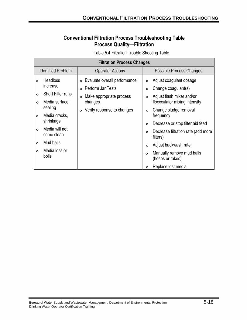
CONVENTIONAL FILTRATION PROCESS TROUBLESHOOTING
Bureau of Water Supply and Wastewater Management, Department of Environmental Protection 5-18 Drinking Water Operator Certification Training
Conventional Filtration Process Troubleshooting Table Process Quality—Filtration
Table 5.4 Filtration Trouble Shooting Table
Filtration Process Changes
Identified Problem Operator Actions Possible Process Changes
o Headloss increase
o Short Filter runs
o Media surface sealing
o Media cracks, shrinkage
o Media will not come clean
o Mud balls
o Media loss or boils
o Evaluate overall performance
o Perform Jar Tests
o Make appropriate process changes
o Verify response to changes
o Adjust coagulant dosage
o Change coagulant(s)
o Adjust flash mixer and/or floccculator mixing intensity
o Change sludge removal frequency
o Decrease or stop filter aid feed
o Decrease filtration rate (add more filters)
o Adjust backwash rate
o Manually remove mud balls (hoses or rakes)
o Replace lost media

UNIT 5 EXERCISE
Bureau of Water Supply and Wastewater Management, Department of Environmental Protection 5-19 Drinking Water Operator Certification Training
Unit 5 Exercise
A. Write the 5 components of Normal operations of conventional filtration on the lines below.
1.
2.
3.
4.
5.
B. Circle all of the following which are indicators of abnormal operating conditions. 6. Filter backwash solids
7. Filter control valves
8. Floc
9. Increased filtered water turbidity
10. Increased raw water turbidity
11. Jar Test
12. Media cracks and shrinkage
13. Mud balls
14. Rapid filter headloss increase
15. Short filter runs
16. Turbidimeter
C. True/False Mark the following statements with at “T” for true or an “F” for false.
___ 17. Process performance monitoring is an ongoing activity for plant operators.
___ 18. New analytical equipment never needs calibration.
___ 19. Some plants use air scour during filter backwash.
___ 20. Jar testing is only needed when a problem occurs.
___ 21. Equipment maintenance is a routine operating procedure.
___ 22. Good floc formation is an indicator of properly operating coagulation/flocculation equipment.
___ 23. Filters only need to be backwashed when dirty.
___ 24. Never take a filter out of service.
___ 25. Media “boils” during filter backwash are an indication of proper cleaning.
___ 26. Raw water alkalinity does not affect the water treatment process.
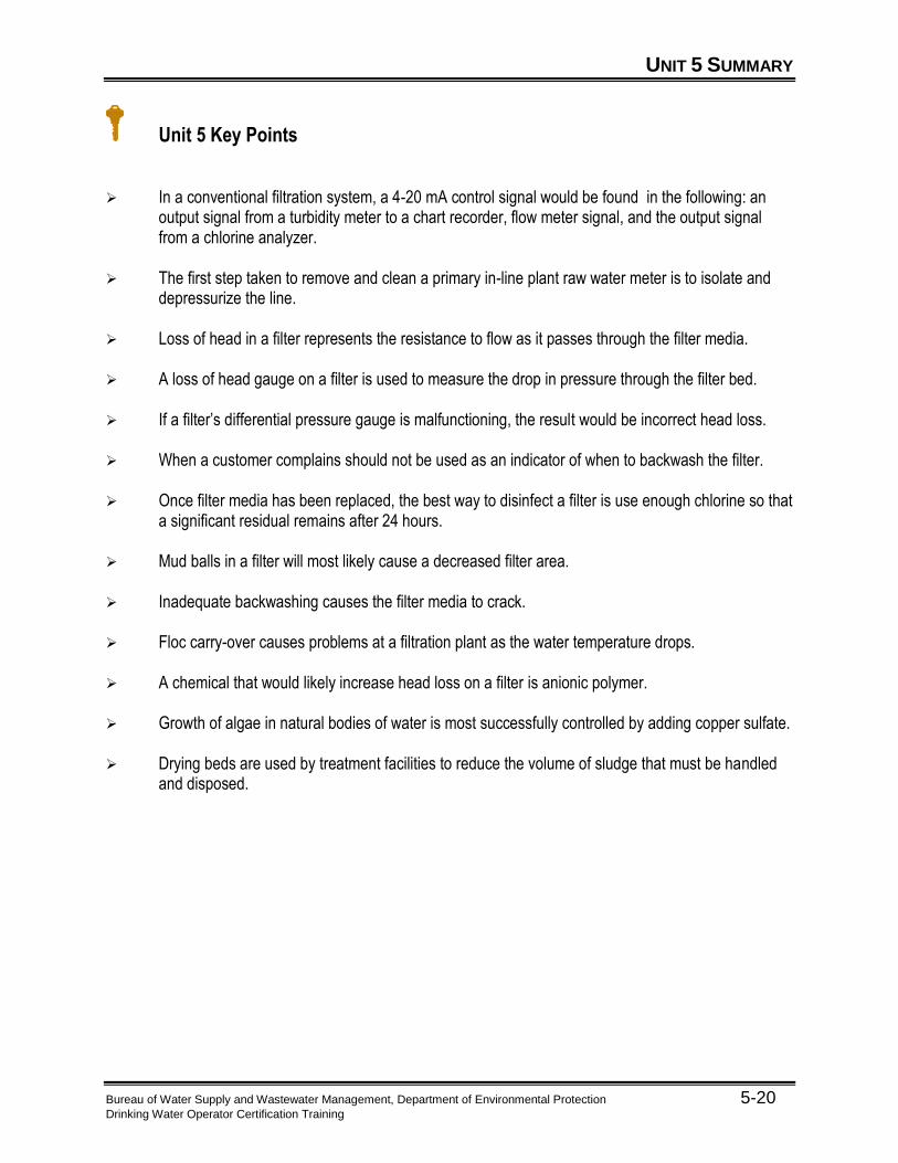
UNIT 5 SUMMARY
Bureau of Water Supply and Wastewater Management, Department of Environmental Protection 5-20 Drinking Water Operator Certification Training
Unit 5 Key Points In a conventional filtration system, a 4-20 mA control signal would be found in the following: an
output signal from a turbidity meter to a chart recorder, flow meter signal, and the output signal from a chlorine analyzer.
The first step taken to remove and clean a primary in-line plant raw water meter is to isolate and
depressurize the line. Loss of head in a filter represents the resistance to flow as it passes through the filter media. A loss of head gauge on a filter is used to measure the drop in pressure through the filter bed. If a filter’s differential pressure gauge is malfunctioning, the result would be incorrect head loss. When a customer complains should not be used as an indicator of when to backwash the filter. Once filter media has been replaced, the best way to disinfect a filter is use enough chlorine so that
a significant residual remains after 24 hours. Mud balls in a filter will most likely cause a decreased filter area. Inadequate backwashing causes the filter media to crack. Floc carry-over causes problems at a filtration plant as the water temperature drops. A chemical that would likely increase head loss on a filter is anionic polymer. Growth of algae in natural bodies of water is most successfully controlled by adding copper sulfate. Drying beds are used by treatment facilities to reduce the volume of sludge that must be handled
and disposed.


![[Insert Photo of Rivers] - PA.Gov](https://static.fdocuments.in/doc/165x107/61a2e270373e26355e623843/insert-photo-of-rivers-pagov.jpg)