Modulation formats for digital fiber transmission Eric Tell 050329.
34
Modulation formats for digital fiber transmission Eric Tell 050329
-
date post
19-Dec-2015 -
Category
Documents
-
view
222 -
download
3
Transcript of Modulation formats for digital fiber transmission Eric Tell 050329.

Modulation formats for digital fiber transmission
Eric Tell 050329
Outline• Fiber performance limitations• WDM• Optical vs. radio communication• Optical modulators• Modulation formats
– Amplitude shift keying
– Duo-binary signalling
– Optical single sideband signalling
• Simulation/experimental results• Summary

Fiber performance limitations
• Fiber Loss
• Chromatic dispersion– different refractive index for different
wavelengths
• Fiber non-linearities

Chromatic dispersion
• Distance limit ~1/(bit rate)²– Example: Single mode fiber @1550nm
• chromatic dispersion: 17ps/km-nm
• dispersion limited distance: ~100km @10Gbit/s
• comparable to loss limit
• EDFA => increased loss-limited distance– Chromatic dispersion becomes the limiting factor in
single mode long-haul fibers!
• We want to decrease the bandwidth for a given datarate!

Wave Division Multiplexing
• Decreased channel spacing leads to interchannel interference and makes it difficult to compensate for fiber nonlinearities
• Narrower subchannels would be nice...

WDM (cont'd)
• In a high capacity link the whole EDFA spectrum is filled with subchannels
• The bandwidth of each subchannel is proportional to its bit rate
• Total fiber capacity is given by the spectral efficency: (bitrate per channel)/(channel spacing)

WDM (cont'd)
• In a practical case using NRZ a spectral efficiency of 40% can be reached
Power spectral density of NRZ
WDM (cont'd
• More GB/s per channel does not increase total bandwith, however– It results in fewer channels to manage– Increased channel spacing decreases
some non-linear distortions• BUT to reach higher spectral efficiency a
format with narrower spectrum for a given bandwidth is needed (while at the same time not increasing other impairments)
How can this be achieved?
• M-ary Amplitude Shift Keying (ASK)
• Duo-binary signaling• Optical Single Sideband (OSSB)
Comparison to radio systems
• Much of the same theory can be applied, except– Carrier frequency is different
• 1550 nm => 194 Thz
– The available components are different• no coherent detection (no PLLs)
– The channel is different

Component imperfections
• Modulators are nonlinear– difficult to achieve pure AM
• PIN photo detectors responds to optical power rather than electrical field amplitude (“square envelope”)
• Dispersion introduces a frequency dependent phase shift
• “intensity-modulated” approaches are used

Optical Modulators
• Direct modulation– directly modulate the drive current of a semiconductor
laser
• Absorbtion modulation– Modulate the absorption spectrum of reverse-biased
diod placed in front of the laser
– Faster and more linear than direct modulation (60 GHz)
• The Mach-Zender (MZ) modulator– modulation my adding phase shifted signals

Optical modulators (cont'd)
• Direct modulators and absorption modulators directly modulates the optical power, but will also generate phase modulation
• The MZ modulator is more flexible and can generate different kinds if modulation other than NRZ/RZ/ASK

The MZ modulator
V1(t)
V2(t)
Ein
Ein/2
γEin/2
Eout
LiNbO3
waveguidecontacts
VtvjVtvjintjtjinout ee
Eee
EE /)(/)()()( 2121
22

MZ modulator transfer function VtvjVtvj
in
out eeE
tEtvtv /)(/)(
2121
2
1)())(),((
VtvtvjetvtvV
tvtv 2/))()((2121
21))()((2
cos())(),((
))(cos( 1 tvV
EE inout
With γ=1 this can be rewritten as:
Amplitude modulation Phase modulation (chirp)
With v1(t)=-v2(t) we remove the phase modulation and get:
))((cos 12 tv
VPP inout
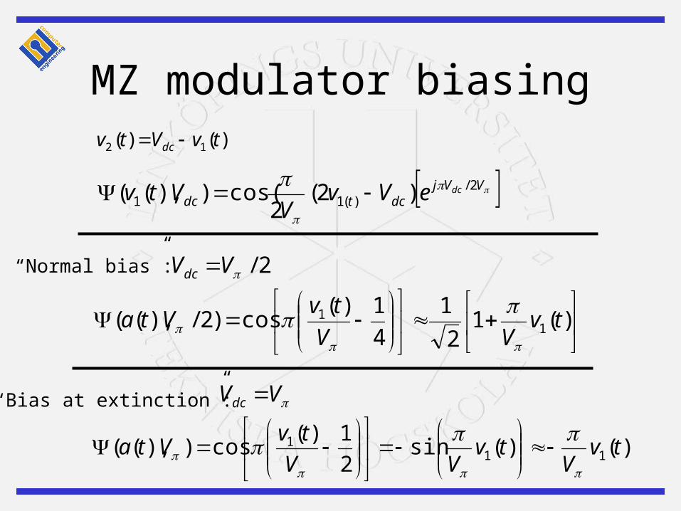
MZ modulator biasing)()( 12 tvVtv dc
VVjdctdc
dceVvV
Vtv 2/)(11 )2(
2cos()),((
2/VVdc
VVdc
)(1
2
1
4
1)(cos)2/),(( 1
1 tvVV
tvVta
)()(sin2
1)(cos)),(( 11
1 tvV
tvVV
tvVta
“Normal bias”:
“Bias at extinction”:
MZ modulators - observations
• These modulators are only linear in a small region– A problem for other than RZ/NRZ signaling
• There must normally be an unmodulated carrier in order to use non-coherent detection

M-ASK• Less bandwidth
• More power needed for a given BER• non-linearities become limiting in
long-haul DWDM systems• More complicated (analog and
digital) electrical circuits• Possibly useful in multi-mode
dispersion limited systems e.g. 10 Gbit/s Ethernet
levels
bandwidth
2 ±B
4 ±B/2
8 ±B/3
16 ±B/4
32 ±B/5
64 ±B/6

Duo-binary signaling
• Introduce correlation between consecutive symbols
• A special case of partial response signaling:

Duo-binary signaling
• Add consecutive symbols => three signal levels
-1,1,1,-1
-2,0,2,0MZ modulator
AM-PSK Duo-binary
• Problem: Normally impractical to handle three levels
• Solution: Use 0,E,-E– The detector will detect two levels 0 and E²– By precoding these two levels will correspond to
0 and 1– a.k.a Amplitude Modulated Phase Shift Keying
(AM-PSK) duo-binary signaling
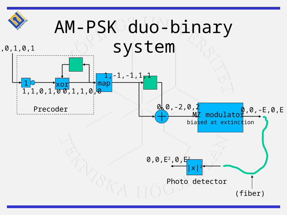
AM-PSK duo-binary system
1,1,0,1,0
MZ modulator biased at extinction
xor map
|x|2
0,1,1,0,0
1,-1,-1,1,1
0,0,-2,0,2 0,0,-E,0,E
1
0,0,1,0,1
0,0,E2,0,E2
(fiber)
Photo detector
Precoder

Optical Single Sideband (OSSB)
• Observation: The frequency spectrum is symmetrical
• Implication: Half of it can be filtered out to save bandwidth => Single Sideband Transmission!
• Used e.g. in TV
Subcarrier OSSB
• In conventional subcarrier modulation the subcarrier appears on both sides of the optical carrier
• Dispersion causes a phase shift between the two signals, which depends on the distance
• At certain points the entire signal is canceled out!
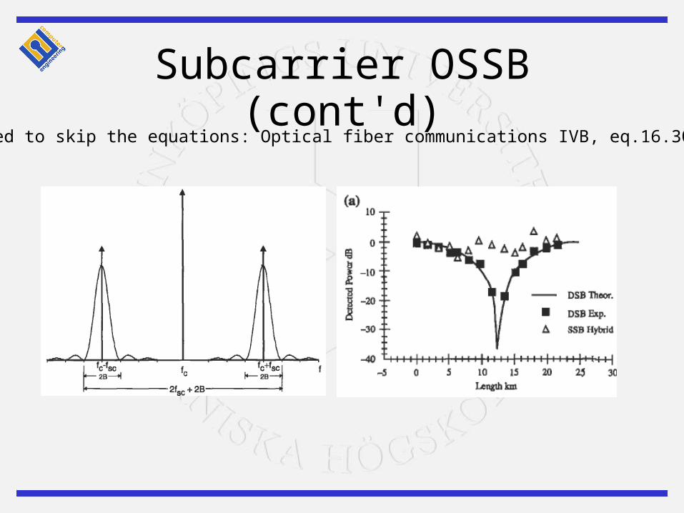
Subcarrier OSSB (cont'd)(decided to skip the equations: Optical fiber communications IVB, eq.16.30-16.36)

Creating an SSB signal
• Two ways– Use a filter (half the energy is lost)– Use the Hilbert transform
• known as a Hartley modulator

Hartley modulator)2sin()(ˆ)2cos()()( tftatftats ccsSSB
)(ˆ)()( tajtats sSSB SSB signal:
Baseband signal:

Optical SSB modulator)(ˆ)()( tajetatg “Approximation” of SSB signal:
MZAmplitudemodulator
Hilberttransform
Phasemodulator
a(t)
Optical carrier
â(t)
OSSB signal

Simulation results: ASK/duo-binary
Dispersion induced receiver sensitivity degradation for Gbit/s signalling

More practical issues…
• ASK– Nees more power =>
non-linearities limiting• Duo-binary
– Needs extra filtering– Optical dispersion
compensation could be an alternative
– 225 km @10Gbit/s 1550 nm has been reached

Experimental results: OSSB
Experimental receiver sensitivity degradation vs. fiber length @ 10Gbit/s, BER=10 -9
DWDM
• “Normal” NRZ– 40% spectral efficiency over 150 km
• Duo-binary AM-PSK– 100% over 100 km
• OSSB– 66% over 300 km

Summary
• Distance between repeaters is limited by either of– Fiber loss– Chromatic dispersion– Fiber non-linearities
• With the advent of EDFA chromatic dispersion has become the limiting factor in long-haul systems
Summary (cont’d)
• We want to limit the bandwidth in order too– Reduce the effects of chromatic dispersion
– Reach higher spectral efficiency in DWDM systems
• Two potential methods:– Duo-binary signaling
– Optical single sideband
• Both methods could potentially halve the bandwidth• None of the methods are currently used in commercial
systems, but there are some promising experimental results


![Design of Ultra High Capacity DWDM System with Different ... · SMF, the advanced modulation formats such as Duo-binary modulation performs well as compared to the NRZ and RZ [5-7].](https://static.fdocuments.in/doc/165x107/5e4995ae66e4d24f3e6633fc/design-of-ultra-high-capacity-dwdm-system-with-different-smf-the-advanced-modulation.jpg)