Modulation - Department of Electrical & Computer...
27
EE3414 Multimedia Communication Systems – Part I Spring 2003, Lecture 5 Modulation Yao Wang Electrical and Computer Engineering Polytechnic University
Transcript of Modulation - Department of Electrical & Computer...

EE3414Multimedia Communication Systems –
Part I
Spring 2003, Lecture 5Modulation
Yao WangElectrical and Computer Engineering
Polytechnic University

EE3414, S03 © Yao Wang, ECE, Polytechnic University 2
Outline
• Need for Modulation in Communication• Modulation of Continuous Signals
– Amplitude Modulation and demodulation• Time domain Interpretation• Frequency domain interpretation
– Frequency Division Multiplexing– Frequency Modulation– Phase Modulation
• Modulation of Digital Signals• Application of Modulation
– AM and FM Radio
EE3414, S03 © Yao Wang, ECE, Polytechnic University 3
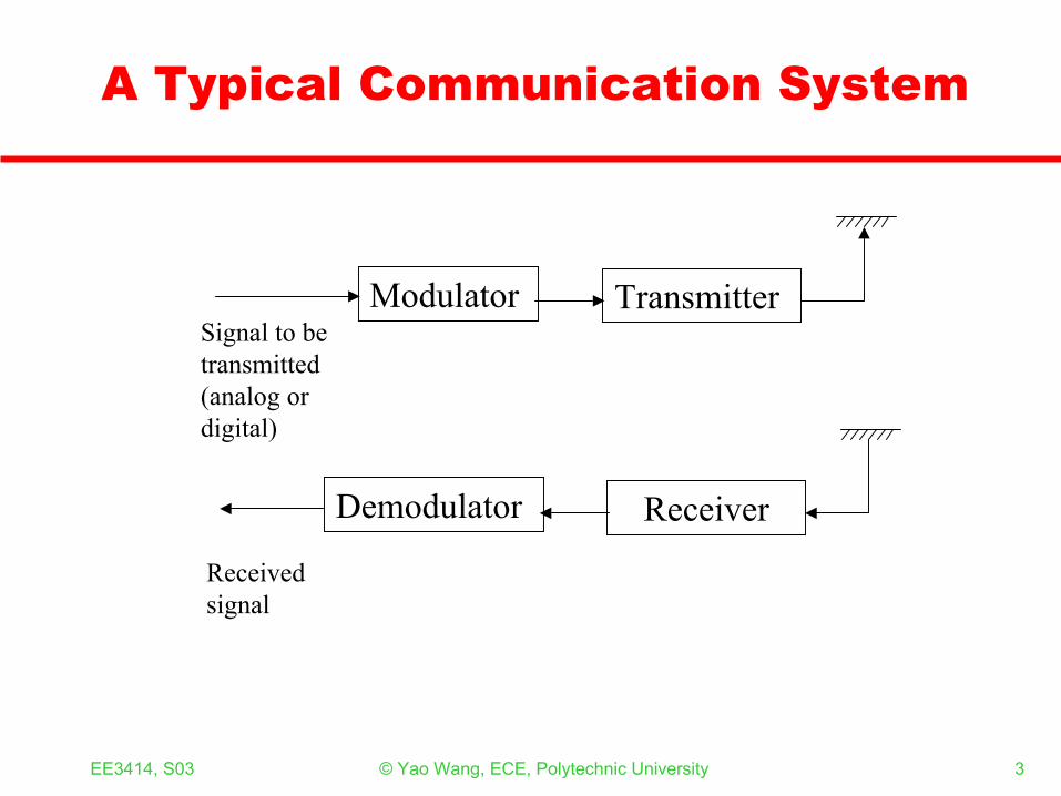
A Typical Communication System
Modulator Transmitter
Demodulator Receiver
Signal to be transmitted(analog or digital)
Received signal

EE3414, S03 © Yao Wang, ECE, Polytechnic University 4
Modulation = Frequency Shifting
0 fc
Baseband signal
Modulated signal
Frequency
EE3414, S03 © Yao Wang, ECE, Polytechnic University 5
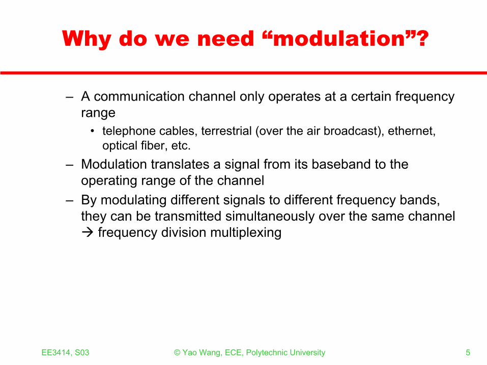
Why do we need “modulation”?
– A communication channel only operates at a certain frequency range
• telephone cables, terrestrial (over the air broadcast), ethernet, optical fiber, etc.
– Modulation translates a signal from its baseband to the operating range of the channel
– By modulating different signals to different frequency bands, they can be transmitted simultaneously over the same channel
frequency division multiplexing
EE3414, S03 © Yao Wang, ECE, Polytechnic University 6
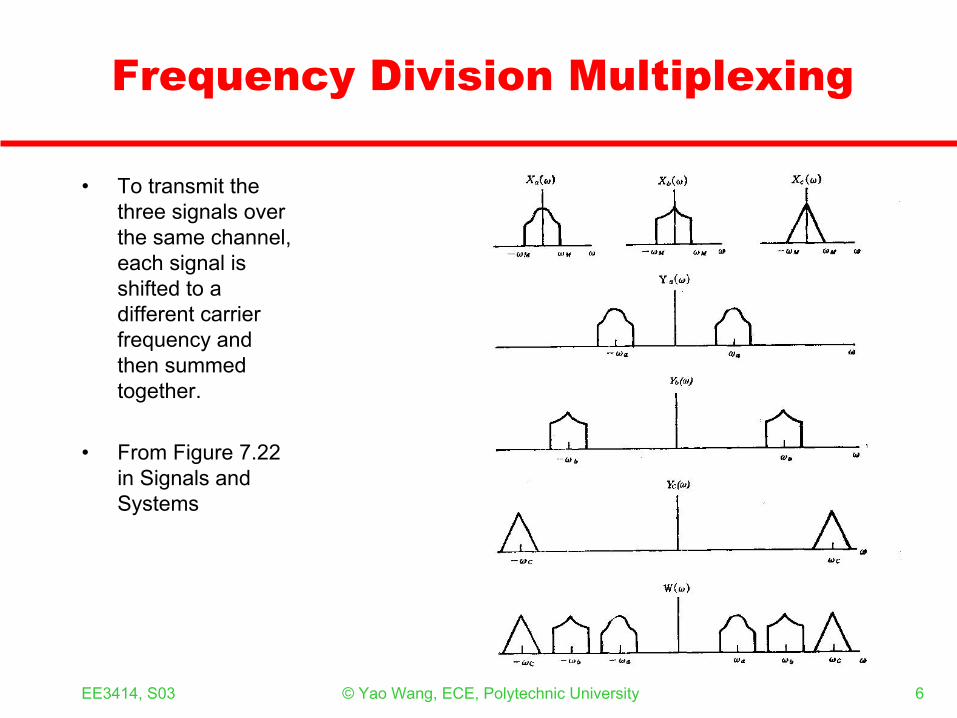
Frequency Division Multiplexing
• To transmit the three signals over the same channel, each signal is shifted to a different carrier frequency and then summed together.
• From Figure 7.22 in Signals and Systems

EE3414, S03 © Yao Wang, ECE, Polytechnic University 7
• By multiplying with a sinusoid signal !
How do we shift the frequency of a signal?
)(tx )cos()()( ttxty cω=
frequencycarrier :signalcarrier )cos(
c
ct
ω
ω
EE3414, S03 © Yao Wang, ECE, Polytechnic University 8
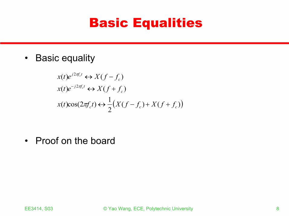
Basic Equalities
• Basic equality
• Proof on the board
( ))()(21)2cos()(
)()(
)()(2
2
ccc
ctfj
ctfj
ffXffXtftx
ffXetx
ffXetxc
c
++−↔
+↔
−↔−
π
π
π

EE3414, S03 © Yao Wang, ECE, Polytechnic University 9
Frequency Domain Interpretation of Modulation
From Figure 7.5 in Signals/Systems
)(tx
)cos( tcω
)cos()()( ttxty cω=

EE3414, S03 © Yao Wang, ECE, Polytechnic University 10
How to get back to the baseband? (Demodulation)
• By multiplying with the same sinusoid + low pass filtering!
)(ty)(tw
)cos( tcωmω− mω−
)(ωH
2)(tx
LPF

EE3414, S03 © Yao Wang, ECE, Polytechnic University 11
Frequency Domain Interpretation of Demodulation
Figure 7.7 in Signals and Systems

EE3414, S03 © Yao Wang, ECE, Polytechnic University 12
Temporal Domain Interpretation
( )
( )
term.second theremove and first term retain the will LPF The
)4cos()(21)(
21)()4cos(1
21)(
)2cos(121)(cosequality theUsing
)2(cos)()2cos()()(:onDemodulati
)2cos()()(:Modulation
2
2
tftxtxtxtftw
tftxtftytw
tftxty
cc
cc
c
ππ
θθ
ππ
π
+=+=
+=
==
=
EE3414, S03 © Yao Wang, ECE, Polytechnic University 13
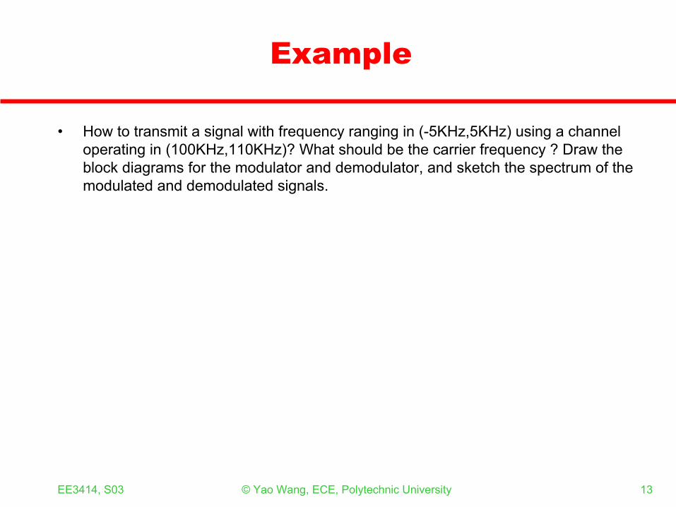
Example
• How to transmit a signal with frequency ranging in (-5KHz,5KHz) using a channel operating in (100KHz,110KHz)? What should be the carrier frequency ? Draw the block diagrams for the modulator and demodulator, and sketch the spectrum of the modulated and demodulated signals.

EE3414, S03 © Yao Wang, ECE, Polytechnic University 14
Technical Challenge
• The demodulator must generate the carrier signal in exactly the same frequency and phase as the modulator – Synchronous modulation

EE3414, S03 © Yao Wang, ECE, Polytechnic University 15
Demodulation by Envelope Detection
Figure 7.14 in Signals and Systems
The modulating signal must be positive!
EE3414, S03 © Yao Wang, ECE, Polytechnic University 16
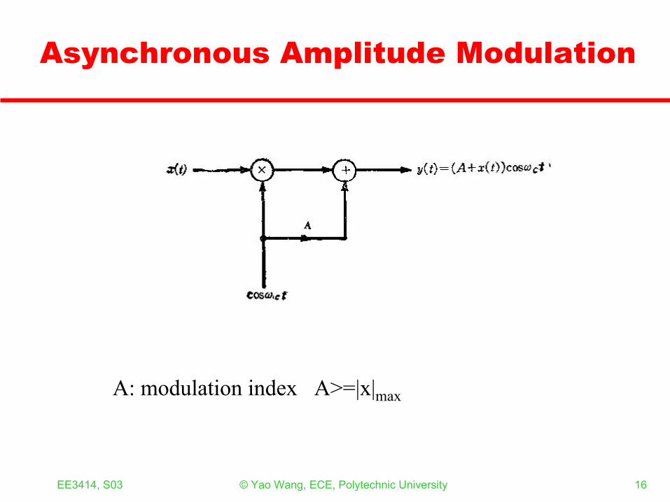
Asynchronous Amplitude Modulation
A: modulation index A>=|x|max

EE3414, S03 © Yao Wang, ECE, Polytechnic University 17
Frequency Domain Interpretation
Figure 7.15 in Signals and Systems
)cos()()( ttxty cω=
( ) )cos()()( tAtxty cω+=
EE3414, S03 © Yao Wang, ECE, Polytechnic University 18
Trade-off between Power Efficiency and Complexity
• Synchronous modulation– Lower transmission power (don’t need to transmit the carrier
signal)– High demodulator complexity (must be synchronized with the
modulator)• Asynchronous modulation
– Higher transmission power– Lower demodulator complexity – Used in AM radio broadcast and receiver

EE3414, S03 © Yao Wang, ECE, Polytechnic University 19
Frequency Division Multiplexing:Frequency domain interpretation
Figure 7.22 in Signals and Systems
)cos()()( ttxty aaa ω=
)cos()()( ttxty aaa ω=
)cos()()( ttxty aaa ω=
)()()()( tytytytw cba ++=

EE3414, S03 © Yao Wang, ECE, Polytechnic University 20
FDM Transmitter
Figure 7.21 in Signals and Systems

EE3414, S03 © Yao Wang, ECE, Polytechnic University 21
FDM Receiver
)cos( taω
Figure 7.23 in Signals and Systems
Demultiplexing Demodulation

EE3414, S03 © Yao Wang, ECE, Polytechnic University 22
Example
• How to transmit two signals each with frequency ranging in (-10KHz,10KHz) over a channel operating in the frequency range (300KHz,340KHz)? Draw the block diagrams for the modulator and demodulator, and sketch the spectrum of the modulated and demodulated signals.
EE3414, S03 © Yao Wang, ECE, Polytechnic University 23
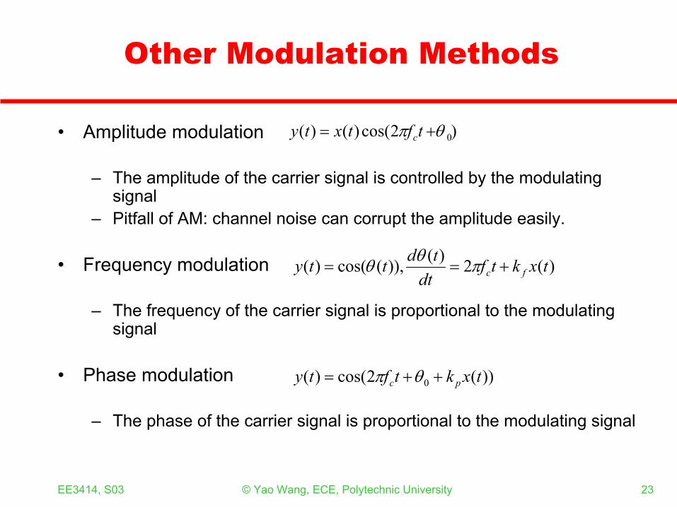
Other Modulation Methods
• Amplitude modulation
– The amplitude of the carrier signal is controlled by the modulating signal
– Pitfall of AM: channel noise can corrupt the amplitude easily.
• Frequency modulation
– The frequency of the carrier signal is proportional to the modulating signal
• Phase modulation
– The phase of the carrier signal is proportional to the modulating signal
)2cos()()( 0θπ += tftxty c
))(2cos()( 0 txktfty pc ++= θπ
)(2)()),(cos()( txktfdttdtty fc +== πθθ

EE3414, S03 © Yao Wang, ECE, Polytechnic University 24
Modulation of Digital signals
0 0 0 00 01 1 1 1 1
Amplitude shift-keying (ASK)
Original signal
Frequency shift-keying (FSK)
Phase shift-keying (PSK)

EE3414, S03 © Yao Wang, ECE, Polytechnic University 25
Application of Modulation and FDM
• AM Radio (535KHz--1715KHz): – Each radio station is assigned 10 KHz, to transmit a mono-channel
audio (bandlimited to 5KHz)– Using Amplitude modulation to shift the baseband signal
• FM Radio (88MHz--108 MHz): – Each radio station is assigned 200 KHz, to transmit a stereo audio.– The left and right channels (each limited to 15KHz) are multiplexed
into a single baseband signal using amplitude modulation– Using frequency modulation to shift the baseband signals
• TV broadcast (VHF: 54-88,174-216MHz, UHF:470-890MHz)– Each station is assigned 6 MHz– The three color components and the audio signal are multiplexed into
a single baseband signal– Using vestigial sideband AM to shift the baseband signals.

EE3414, S03 © Yao Wang, ECE, Polytechnic University 26
What Should You Know
– Understand the principle of amplitude modulation• Know how to modulate a signal to a certain frequency• Know how to demodulate a signal back to the baseband• Can write the equation and draw block diagram for both modulation and
demodulation• Can plot the signal spectrum after modulation and demodulation• Know the difference between synchronous and asynchronous modulation
and trade-offs– Understand the principle of frequency division multiplexing
• Can write the equation and draw block diagram for both modulation and demodulation, for multiplexing of two to three signals.
– Understand how the AM and FM radio works in terms of modulation and multiplexing.
EE3414, S03 © Yao Wang, ECE, Polytechnic University 27
References
• A. M. Noll, Chapter 10.• A. V. Oppenheim and A. S. Willsky, Signals and Systems, 1st ed,
Chapter 7 (or 2nd edition, Chapter 8)