Modulated Properties of Fully Absorbable Bicomponent Meshes
269
Clemson University TigerPrints All Dissertations Dissertations 12-2010 Modulated Properties of Fully Absorbable Bicomponent Meshes Shawn Peniston Clemson University, [email protected] Follow this and additional works at: hps://tigerprints.clemson.edu/all_dissertations Part of the Biomedical Engineering and Bioengineering Commons is Dissertation is brought to you for free and open access by the Dissertations at TigerPrints. It has been accepted for inclusion in All Dissertations by an authorized administrator of TigerPrints. For more information, please contact [email protected]. Recommended Citation Peniston, Shawn, "Modulated Properties of Fully Absorbable Bicomponent Meshes" (2010). All Dissertations. 647. hps://tigerprints.clemson.edu/all_dissertations/647
Transcript of Modulated Properties of Fully Absorbable Bicomponent Meshes

Clemson UniversityTigerPrints
All Dissertations Dissertations
12-2010
Modulated Properties of Fully AbsorbableBicomponent MeshesShawn PenistonClemson University, [email protected]
Follow this and additional works at: https://tigerprints.clemson.edu/all_dissertations
Part of the Biomedical Engineering and Bioengineering Commons
This Dissertation is brought to you for free and open access by the Dissertations at TigerPrints. It has been accepted for inclusion in All Dissertations byan authorized administrator of TigerPrints. For more information, please contact [email protected].
Recommended CitationPeniston, Shawn, "Modulated Properties of Fully Absorbable Bicomponent Meshes" (2010). All Dissertations. 647.https://tigerprints.clemson.edu/all_dissertations/647
i
MODULATED PROPERTIES OF FULLY ABSORBABLE
BIOCOMPONENT MESHES
A Dissertation
Presented to
the Graduate School of
Clemson University
In Partial Fulfillment
of the Requirements for the Degree
Doctor of Philosophy
Bioengineering
by
Shawn J. Peniston
December 2010
Accepted by:
Dr. Karen J. L. Burg, Committee Chair
Dr. Shalaby W. Shalaby, Co-Advisor
Dr. Jiro Nagatomi
Dr. Ken Webb

ii
ABSTRACT
Current meshes used for soft-tissue repair are mostly composed of single
component, nonabsorbable yarn constructions, limiting the ability to modulate their
properties. This situation has left the majority of soft tissue repair load-bearing
applications to suffer distinctly from undesirable features associated, in part, with mesh
inability to (1) possess short-term stiffness to facilitate tissue stability during the
development of wound strength; (2) gradually transfer the perceived mechanical load as
the wound builds mechanical integrity; and (3) provide compliance with load transfer to
the remodeling and maturing mesh/tissue complex. The likelihood of long-term
complications is reduced for fully absorbable systems with degradation and absorption at
the conclusion of their intended functional performance.
The primary goal of this dissertation was to develop and characterize a fully
absorbable bicomponent mesh (ABM) for hernia repair which can modulate
biomechanical and physical properties to work with the expected needs of the wound
healing process. The first study reviewed the current state of hernioplasty and proposed
the subject device. The second study investigated different knitting technologies to
establish a mesh construction which temporally modulated properties. To this end, a
novel construction using warp knitting was developed where two degradable copolyester
yarns with different degradation profiles were coknit into an initially interdependent knit
construction. The developed knit construction provided an initial high level of structural
stiffness; however, upon degradation of the fast-degrading yarn the mesh comprised of
the slow-degrading yarn was liberated and affords high compliance. In the third study,

iii
the segmented, triaxial, high-glycolide copolyester used as the fast-degrading yarn was
optimized to retain strength for greater than 18 days. As such, the ABM physical and
biomechanical transition was designed to temporally coincide with the expected
commencement of wound strength.
The fourth study investigated the in vivo tissue response and integration of the
developed degradable copolyester yarns in a novel construct to simulate the ABM.
Results indicated a strong initial inflammatory response which resolved quickly and an
integration process that produced a dense, compacted, and oriented collagen capsule
around the implant during the transition phase. For the final study, the clinically-relevant
biomechanical properties of two different ABM constructions were compared against
traditional hernia meshes. Using a novel synthetic in vitro simulated mesh/tissue
complex, the ABM were found to provide significantly greater early stability, subsequent
biomechanics that approximated that of the abdominal wall, and evidence of restoring
endogenous tension to the surrounding tissue. These results were in marked contrast to
traditional hernia meshes which showed stress shielding and significantly greater stiffness
than the abdominal wall.

iv
DEDICATION
I dedicate this work to my wife, Kristin, who has brought me so much love,
happiness, and understanding through this process. I could not have done it without her.
To my parents, Marsha and Jim, who have supported my dreams, whatever they might be
and wherever they might have taken me. To my late Grandmother, Francis, who on
many occasions told me to “Stick to the books, they‟ll pay off.” She was right. Finally,
to the rest of my loving family who have provided me with the encouragement to achieve
this milestone.

v
ACKNOWLEDGMENTS
I am indebted to my advisor, Dr. Karen J. L. Burg, for her positive comments,
detailed guidance, and hard work in the preparation of this dissertation. I am forever
grateful to the late Dr. Shalaby and his family. Dr. Shalaby‟s life long journey of
acquiring knowledge, tremendous work ethic, and his passion for science provided me
with this opportunity. My life is forever changed for knowing him.
I would also like to thank Dr. Jiro Nagatomi and Dr. Ken Webb for their time,
support, and constructive comments. Thank you to Dr. Gerrard for his assistance with
the statistical analysis and Linda Jenkins for her help in the histology lab. Thank you to
Dr. Joel Corbett who performed the animal surgical procedures and the Godley-Snell
research center staff at Clemson University for providing the animal care. A special
thanks to all of my Poly-Med friends who have encouraged me, taught me, and assisted
me over the past six years. Of course, thank you to all of my past professors who have
taken the time to share their knowledge. In that spirit, I will take the time to share what I
have learned with others as well.

vi
TABLE OF CONTENTS
Page
TITLE PAGE .................................................................................................................... i
ABSTRACT ..................................................................................................................... ii
DEDICATION ................................................................................................................ iv
ACKNOWLEDGMENTS ............................................................................................... v
LIST OF TABLES .......................................................................................................... ix
LIST OF FIGURES ......................................................................................................... x
PREFACE ..................................................................................................................... xiv
CHAPTER
1. LITERATURE REVIEW .............................................................................. 1
The Wound Healing Process .................................................................... 1
Anatomy and Biomechanics of the Abdominal Wall .............................. 9
Hernia Development and Surgical Intervention
Using Meshes ................................................................................... 15
Etiology and Pathology of Hernia Development ................................... 23
Knitting Technologies and Their Relevance to the Properties
of Surgical Meshes ........................................................................... 29
Meshes as Biomaterials.......................................................................... 34
Biocompatibility – Meshes and Biologic Environment ......................... 45
New Opportunities Based on Currently Unmet Needs .......................... 59
References .............................................................................................. 62

vii
Table of Contents (Continued)
Page
2. EFFECT OF MESH CONSTRUCTION ON THE
PHYSICOMECHANICAL PROPERTIES OF
BICOMPONENT KNIT MESH USING YARNS
DERIVED FROM DEGRADABLE COPOLYESTERS ...................... 80
Introduction ............................................................................................ 80
Materials and Methods ........................................................................... 86
Results .................................................................................................... 95
Discussion ............................................................................................ 110
Conclusion ........................................................................................... 118
References ............................................................................................ 128
3. EFFECT OF CHEMICAL COMPOSITION AND THERMAL
TREATMENT ON THE PROPERTIES OF MULTIFILAMENT
YARNS MADE OF SEGMENTED HIGH-GLYCOLIDE
COPOLYESTERS ............................................................................... 127
Introduction .......................................................................................... 127
Materials and Methods ......................................................................... 135
Results .................................................................................................. 141
Discussion ............................................................................................ 158
Conclusion ........................................................................................... 169
References ............................................................................................ 171
4. AN INVESTIGATION OF THE TISSUE RESPONSE AND
INTEGRATION OF AN ABSORBABLE BICOMPONENT
CONSTRUCT IN A RAT MODEL .................................................... 175
Introduction .......................................................................................... 175
Materials and Methods ......................................................................... 178
Results .................................................................................................. 183
Discussion ............................................................................................ 190
Conclusion ........................................................................................... 194
References ............................................................................................ 195

viii
Table of Contents (Continued)
Page
5. A COMPARISON OF THE CLINICALLY RELEVANT
BIOMECHANICAL PROPERTIES OF WARP KNIT,
FULLY ABSORBABLE BICOMPONENT MESHES
WITH TRADITIONAL MESHES FOR HERNIA
REPAIR ............................................................................................... 198
Introduction .......................................................................................... 198
Materials and Methods ......................................................................... 204
Results .................................................................................................. 213
Discussion ............................................................................................ 229
Conclusion ........................................................................................... 240
References ............................................................................................ 242
CONCLUSIONS.......................................................................................................... 251
RECOMMENDATIONS ............................................................................................. 252

ix
LIST OF TABLES
Table Page
2.1 Traditional and Proposed Additional Design Criteria
for a Hernia Mesh .................................................................................. 81
2.2 Polymerization Scheme and Analytical Data for
MG-9 and SMC-7 .................................................................................. 95
2.3 Typical Physical and Mechanical Properties of MG-9
and SMC-7 Yarn .................................................................................... 97
2.4 Initial and In Vitro Conditioned Mesh Physical Properties
for the DM1 and WK1 Meshes ............................................................ 100
3.1 Polymerization Scheme and Analytical Data for MG-9
and MG-17 ........................................................................................... 141
3.2 Physical and Initial Mechanical Properties of MG-9
and MG-17 Yarn .................................................................................. 142
3.3 Initial Thermal and Mechanical Properties “As Extruded”
and Annealed MG-9 and MG-17 Yarn ................................................ 143
3.4 Thermomechanical Properties of “As Extruded” and
Annealed MG-9 and MG-17 Yarn Determined by DMA .................... 149
3.5 Percent Shrinkage and Shrinkage Onset Temperature
of “As Extruded” and Annealed MG-9 and MG-17 Yarn ................... 150
5.1 Initial and In Vitro Conditioned Mesh Physical Properties for
the ABM, PET, and PP ........................................................................ 215
5.2 Suture Pullout Force, Tear Resistance, and Flexural Stiffness
Data for the ABM and Traditional Meshes .......................................... 217
5.3 Burst Test Data for the ABM and Traditional Meshes .............................. 218

x
LIST OF FIGURES
Figure Page
1.1 The myopectineal orifice depicting the medial, lateral,
and femoral triangles.............................................................................. 10
1.2 Posterior view of the inguinal region demonstrating a weak
medial area caused by arching fibers of the internal
oblique and transversalis fascia ............................................................. 11
1.3 Anterior view of the inguinal region ............................................................ 12
1.4 Mesh placement for the Lichtenstein procedure .......................................... 18
1.5 The laparoscopic techniques for hernia repair ............................................. 20
1.6 Knitted fabric from a simple weft and a single guide bar,
half-tricot warp knit construction........................................................... 31
1.7 Examples of a short underlap mesh (half-tricot), an open work
mesh (sand-fly net), and a lay-in mesh
(3-guide bar marquisette) ....................................................................... 33
1.8 The modulated mechanical characteristics of a multicomponent
mesh superimposed with the wound healing response .......................... 60
2.1 Images of the knit construction for the DM1 and WK1 mesh ..................... 98
2.2 Images of the components of the DM1 and WK1 mesh ............................. 99
2.3 The initial extension at 16 N/cm in the wale and course
directions for the DM1 and WK1 meshes during
mechanical tensile testing .................................................................... 102
2.4 Force-extension data for initial tensile testing of the DM1
and WK1 meshes in the wale and course directions ............................ 103
2.5 The temporal in vitro conditioned maximum breaking force
in the course and wale directions for the DM1 and WK1
meshes during mechanical tensile testing ............................................ 104

xi
List of Figures (Continued)
Figure Page
2.6 The temporal in vitro conditioned extension at 16 N/cm
in the course and wale directions for the DM1 and
WK1 mesh during mechanical tensile testing ...................................... 105
2.7 The temporal in vitro conditioned maximum burst force for
the DM1 and WK1 mesh during mechanical burst testing .................. 107
2.8 The temporal in vitro conditioned extension at 16 N/cm for
the DM1 and WK1 mesh during mechanical burst testing .................. 109
3.1 The storage modulus (E‟), loss modulus (E‟‟), and tan δ response
for the “as extruded” (top) and annealed (bottom, 120°C
for 60 minutes) MG-9 (dashed) and MG-17 (solid) yarn .................... 145
3.2 The typical tan δ response of annealed MG-9 and MG-17 yarn
depicted for the annealing temperature of 120ºC conditioned
for the times of 30 (blue), 60 (green), and 180 (maroon) minutes....... 146
3.3 The typical tan δ response of annealed MG-9 and MG-17 yarn
depicted for the annealing time of 30 minutes conditioned
at the temperatures of 100°C (blue), 120°C (green), and
140°C (maroon) ................................................................................... 148
3.4 A typical Arrhenius plot demonstrating the relationship
between logarithmic frequency and reciprocal peak
temperature for the Tg transition ......................................................... 152
3.5 The apparent activation energies of the Tg transition calculated
from the slope of the Arrhenius plot .................................................... 153
3.6 The temporal in vitro conditioned maximum tensile force for
MG-9 and MG-17 samples annealed at 100ºC for 30, 60,
and 180 minutes ................................................................................... 154
3.7 The temporal in vitro conditioned maximum tensile force for
MG-9 and MG-17 samples annealed at 120ºC for 30, 60,
and 180 minutes ................................................................................... 156

xii
List of Figures (Continued)
Figure Page
3.8 The temporal in vitro conditioned maximum tensile force for
MG-9 and MG-17 samples annealed at 140ºC for 30, 60,
and 180 minutes ................................................................................... 157
4.1 Images of ABC and PETC showing the knit construction and
high aspect ratio ................................................................................... 184
4.2 The granuloma thickness for the ABC and PETC implants at the
implantation periods of 3 and 6 weeks ................................................ 185
4.3 The capsule thickness for the ABC and PETC implants at the
implantation periods of 3 and 6 weeks ................................................ 186
4.4 Histological sections of the tissue/implant interface in rat gluteal
muscle for the ABC and PETC at 3 and 6 weeks post
implantation ......................................................................................... 187
4.5 The collagen/total protein ratio for the ABC and PETC implants
at the implantation periods of 3 and 6 weeks ....................................... 189
5.1 The modulated mechanical characteristics of a bicomponent
mesh superimposed with the temporal wound healing
response................................................................................................ 199
5.2 Images of knit construction for the WK6 and WK7 meshes ..................... 213
5.3 Images of the knit construction for the WK6, WK7, PP, and
PET meshes .......................................................................................... 214
5.4 The temporal in vitro conditioned maximum burst force for the
ABM during mechanical burst testing ................................................. 219
5.5 The temporal in vitro conditioned extension at 16N/cm for the
ABM during mechanical burst testing ................................................. 220
5.6 FEP data for burst testing of ABM, PET, and PP meshes ......................... 222
5.7 FEP data for multiaxial burst testing of SMTC using
traditional meshes ................................................................................ 224

xiii
List of Figures (Continued)
Figure Page
5.8 FEP data for multiaxial burst testing of SMTC using ABM ..................... 226
5.9 FEP data for uniaxial tensile testing of SMTC using PET and
PP mesh in the course direction ........................................................... 227
5.10 FEP data for uniaxial tensile testing of SMTC using ABM
in the course direction .......................................................................... 228

xiv
PREFACE
Over one million surgical procedures for hernia repair using a mesh are completed
every year worldwide. Despite the frequency of this procedure, the efficacy of hernia
repair remains a challenge with high recurrence rates and a substantial percentage of
patients that experience long-term complications which impact quality of life. Scientific
literature is replete with animal and clinical studies which demonstrate the unmet need
for a hernia mesh with improved biocompatibility.
This dissertation describes a bioengineering approach that was used to develop
and evaluate a novel hernia mesh which considers the temporal needs of the wound
healing process, as well as the device functional needs to improve biocompatibility.
Specifically, a bicomponent fully-absorbable warp knit mesh was proposed which
temporally modulates its physicomechanical properties and will (1) possess short-term
structural stiffness to facilitate tissue stability during the development of wound strength;
(2) gradually transfer the perceived mechanical loads as the wound is building
mechanical integrity; (3) provide force-extension properties similar to the abdominal wall
resulting in load transfer to the remodeling and maturing mesh/tissue complex; and (4)
minimize the likelihood of long-term complications with complete degradation and
absorption at the conclusion of the meshes intended function.
This dissertation consists of five chapters which cover the unmet clinical needs,
conceptual evaluation, and the design and development history for the subject absorbable
bicomponent mesh (ABM). The first chapter provides a detailed review of the wound
healing process, anatomy and biomechanics of the abdominal wall, hernia development

xv
and surgical intervention using meshes, etiology and pathology of hernia development,
knitting technologies for meshes, meshes as biomaterials, mesh biocompatibility, and
new opportunities based on currently unmet needs. In summary, Chapter 1 details the
background including the current challenges associated with traditional hernia repair
meshes and a proposed novel concept which evolved further in subsequent chapters.
Chapters 2 through 5 represent individual studies written in the format found in
most scientific journals. Each chapter details a step in the development process for the
ABM. In Chapter 2, two different mesh constructions were knit to determine the effect
of knit construction on the temporal modulation of physicomechanical properties during
the in vitro conditioned degradation of the fast-degrading yarn. The outcome resulted in
the adoption of a novel warp knit construction whereby two initially interdependent knit
constructions provide a high level of structural stiffness. However, the substantial
degradation of the fast-degrading yarn yields an autonomous, structurally stable and
compliant slow-degrading mesh. The study in Chapter 3 focuses on the development and
optimization of a segmented, triaxial, high-glycolide copolyester for use as the fast-
degrading yarn which retained strength for greater than 18 days to temporally coincide
the biomechanical transition with the expected commencement of wound strength.
The second and third chapters detail the work completed to establish the
necessary absorbable copolyesters and knit technology required to meet the initially
proposed design concept described in Chapter 1. In Chapter 4, an ABM mesh was
prototyped using a simplified knit construct to complete a preliminary in vivo study. In
this study the tissue response to the simulated ABM was investigated with specific

xvi
emphasis placed on the integration of the mesh into the host tissue using evaluation time
periods which bracket the critical biomechanical transition from structural stiffness to
high extensibility. In Chapter 5, a mesh biomechanical study investigated the effect of
two different ABM knit constructions on physicomechanical properties with comparison
to two traditional hernia meshes. As part of this investigation, a novel simulated mesh
tissue/complex using a synthetic material was developed to demonstrate the change in
mesh biomechanics following infiltration with the extracellular matrix in vivo.
Additionally, the strength retention of the slow-degrading yarn was determined to be
load-bearing for greater than 9 months, which is the expected time period for the
sufficient maturation of the infiltrated collagen.
The completed work described in this dissertation is an initial effort to develop a
novel ABM with expected improved mechanical biocompatibility. The intellectual
property associated with this dissertation is the subject of patent applications in several
countries worldwide, a limited 40 patient clinical study in Sweden initiated in early 2009,
and 510K approval from the Food and Drug Administration for clinical use in the United
States in early 2010. Additionally, the contents of Chapter 1 were used to develop a
chapter in the book “Mechanobiology Handbook” edited by Dr. Jiro Nagatomi which is
currently in press. Results from Chapter 2 were presented at the 2008 Clemson
University Annual Conference on Opportunities and Markets for Medical Materials and
Technologies.

1
CHAPTER ONE
LITERATURE REVIEW
The Wound Healing Process
Wound healing is characterized by several overlapping, predictable stages that are
strongly interlinked and contribute to the common goals of the elimination of foreign
microorganisms, wound debridement, cell proliferation, matrix deposition, contraction,
and maturation resulting in mechanical integrity.
Stages of Wound Healing
The major stages of wound healing include inflammation (generally 2-5 days post
insult), proliferation (generally 2 days to 3 weeks post insult), and remodeling/maturation
(generally 3 weeks to 2 years post insult). The timeframes are approximated because of
the complex and often case specific nature of wound healing. Many factors affect the
timing of the wound healing process, including the location and extent of injury, level of
wound contamination and infection, rate of fluid perfusion, level of local pH, presence of
foreign bodies, host comorbidities, and the regenerative capacity of proximal cells.1,2
The wound healing process is sequentially similar throughout the body with differences
specific to the length of each stage and cell autocrine and paracrine signaling often
resulting in anatomical site specific cell responses such as atrophy, hypertrophy,
hyperplasia, metaplasia, and/or phenotype changes. The end result of orderly and timely
wound healing is ideally tissue with minimal fibrosis yet structural integrity, minimal to

2
no wound contraction, and pre-injury function. Often with the implantation of medical
devices the measure of their biocompatibility is graded on the local resolution of the
wound healing process in a timely manner. To better understand this process a brief
review of the typical, wound healing process is helpful.
Injury to vascularized tissue triggers coagulation and the initiation of the
inflammation process of wound healing. The inflammation process rapidly increases to a
maximum at 2-3 days and then gradually resolves over the next couple of weeks.
Overall, the inflammatory process can be divided into two stages of (1) vasomotor-
vasopermiability and (2) leukocyte signaling and infiltration.3 The initial vascular
response to injury is a short lived vasoconstriction intended to minimize blood loss
followed by a period of local vasodilation. Vasodilation increases the pressure and flow
of blood to the area and causes the release of serum fluid through permeable vascular
walls resulting in tissue oedema. Within the newly formed interstitial space created by
the exudate, proteins such as fibronectin are deposited which will create the initial
scaffolding for subsequent cellular migration and locomotion into and within the wound.3
Within the wound site, the formation of a blood clot via the coagulation cascade blocks
the continued loss of blood and provides additional scaffolding for cellular activity during
the remodeling phase. The blood clot is constructed from fibrin, an insoluable,
crosslinked product of fibrinogen, and activated platelets. During the formation of the
blood clot, activated platelets release a myriad of cytokines including platelet derived
growth factors (PDGF)4 and transforming growth factor (TGF-β)
5 which result in the
chemotaxis of leukocytes and fibroblasts. The first cell type to aggregate at the wound

3
site is the neutrophil. The primary role of the neutrophil is to clean the wound by
removing bacteria and initiating debridement.3,6
Neutrophils accomplish this goal
through the release of free oxygen radicals and lysosomal enzymes from within their
many intracellular granules. Neutrophils are short lived within wounds, especially when
bacterial infiltration is minimal, and quickly (generally by day 3) become secondary in
number to monocytes differentiating to macrophages. Macrophages continue to
phagocytize tissue and bacterial debris taking over where the neutrophils left off;
however, macrophages have the added responsibility of being crucial to cellular
proliferation and recruitment. Once the wound is clear of bacteria and debris the
rebuilding process can begin with the repopulation of cells.
The proliferation and remodeling phase is characterized by the increase in
fibroblasts followed by the deposition of extra cellular matrix (ECM) in the wound.
Proliferation is driven by macrophages that secrete growth factors such as PDGF, TGF-β,
interleukins (IL), and tumor necrosis factor (TNF) which play key roles in the migration
and activation of local fibroblasts.3 Fibroblasts, which originate from mesenchymal cells
located in loose tissue around blood vessels and fat, differentiate and migrate in response
to these cytokines.7 Theses newly formed fibroblasts use the fibrin/fibronectin network
previously established for locomotion within the wound. In addition to collagen,
fibroblasts produce glycoaminoglycans (GAGs) and proteoglycans which form the tissue
“ground substance”. Initially fibroblasts are primarily focused on replication and
recruitment with minimal collagen synthesis. Within the first 4-6 days following insult,
fibroblasts become the primary cell type and the deposition of collagen increases rapidly

4
for the next three weeks.6 Concurrently during the three week time period of collagen
deposition, angiogenesis progresses to provide the wound with nourishment and oxygen
while removing metabolic and waste products. Macrophages and fibroblasts provide the
stimulus for the progression of capillaries, arterioles, and venules toward the wound
space. The generation of fibroblast growth factor (FGF) and vascular endothelial growth
factor (VEGF) from macrophages are the primary, and most studied, cytokines
responsible for angiogenesis.8 Over time capillaries slowly regress as collagen fills the
wound space and mature, avascular scar tissue is formed.
Wound remodeling and maturation is characterized by a gradual strengthening
and reorganization of the collagen matrix over a period as short as 3 weeks or as long as 2
years. During this time, Type III collagen, so called immature collagen because of its
smaller fiber diameter, greater elasticity, and lower strength, is replaced by Type I
collagen. Prior to the deposition of Type I collagen the wound has essentially no
mechanical integrity. During the wound maturation/remodeling process no net gain in
collagen content is achieved; instead, the production of collagen is matched by the
degradation of collagen by matrix metalloproteinase‟s (MMPs). With the turnover of
Type III collagen to Type I collagen the wound site develops mechanical strength and the
cells attempt to replicate the preinjury tissue characteristics by contributing to the
developing structure and orientation along the lines of tension. However, typically the
wound site never fully obtains the original tissue structure, while values of approximately
80% of preinjury mechanical strength are reported.5

5
The Role of Fibroblasts and Collagen in Soft
Tissue Wound Healing
Collagen is the most widespread protein present in humans and consists of fibrils
embedded in an amorphous gel-like matrix composed of proteoglycans and water. Fiber
forming collagen, such as Types I and III, function to transmit and dissipate loads and
store elastic strain energy applied to the joints of the body.9 The mechanical
characteristics of collagen lie in its unique and somewhat complex structure.
The development of collagen, the structural component to soft tissue, is
paramount to effective and efficient resolution in wound healing. Collagen is synthesized
by fibroblasts in a multiple step process that starts with intracellular assimilation of
peptide chains and is completed with extracellular collagen fiber and fiber bundle
formation into macroscopic structures such as tendons or fascia.
Within wounds, collagenous tissue function is highly dependent on its structure.
Collagen fibrils are highly oriented and thus strong but they can be considered essentially
inextensible.10
The conformation of collagen fibrils is essential to determining tissue
function. For example, highly oriented structures such as tendons transmit force quickly
and efficiently while randomly oriented fibers in the dermis allow considerable extension
before resistance is achieved. Therefore, the aggregation of fibrils into fibers and their
resultant diameter as wells as the construction of the aggregate fibers gives soft tissue its
mechanical properties and anatomically specific characteristics. The stress-strain curve
for collagen tissue is non-linear and can be divided into three distinct regions, each of
which can be attributed to a different structural element. In tendon and ligament the
curve has been characterized by a low strain non-linear toe region, a curved mid-region,

6
and then a linear yield and failure region.11
In the toe region, low stress is required to
remove macroscopic crimp in the form of gradual straightening of collagen fibers that
have varying degrees of undulations.12
The second region is characterized by collagen
fibers that begin to line-up in the direction of the load and provide increasing resistance.
In addition, disordered molecules in the lateral gap region between fibrils reorganize.13
In the third region, stretching of the triple-helices and crosslinks between helices produce
side-by-side gliding of neighboring collagen molecules leading to structural changes at
the level of the collagen fibrils.14
Under typical conditions, physiologic levels are within
the toe region of the stress-strain curve, resulting in a shock absorbing system, where low
levels of stress are required to achieve deformations in the absence of significant
molecular stretching of the fibers.10
Like synthetic polymers, biopolymers such as collagen are viscoelastic. The
hierarchical structure of collagen, from triple-helix to tissue, provides structural
components that have elastic and viscous characteristics. For example, ligament
viscoelasticity under uniaxial tensile loading is attributed to the inherent viscoelasticity of
the collagen fibrils (bond rotation and stretching), the local extracellular matrix,
interfibrillar crosslinking, and the movement of fluid within and in/out of the tissue.15
The degree of crosslinking between fibrils has been linked to viscoelastic properties, with
low levels dominating viscous behavior and high levels dominating elastic behavior
through the stretching of nonhelical ends, crosslinks, and the triple helix.9 Furthermore,
it has been determined that the overall strain in a tendon is always larger than the strain of

7
individual fibrils, indicating that some of the viscoelastic deformation takes place in the
proteoglycan-rich interfibrillar matrix.14
Influence of Mechanical Stimulation in the Soft Tissue
Wound Healing Process
Mechanical forces are fundamental in maintaining and regulating the structure
and function of tissue. The importance of the mechanical loading of bone has been
realized for many years; more recently, the importance of mechanical stimulation on
other tissues such as ligament, tendon, skeletal muscle, intervertabral disc, and meniscus
is being realized.16
The influence of mechanotransduction in cellular signaling is still not
fully understood. However, the influence of mechanical stimulation on fibroblasts has
been investigated and determined to affect cell proliferation17,18
, collagen deposition19,20
,
phenotype21
, apoptosis22
, cell spreading23
, orientation24
, and the release of matrix
metalloproteinases25
. From a biochemical aspect, observed changes in animal tendons
and ligaments from joint immobilization studies include increases in the rate of collagen
turnover, reduced levels of crosslinking, slight mass loss, a reduced amount of
proteoglycans and hyaluronic acid, and decreased water content.26
Biomechanically, the
result of these changes is a reduction in tangent modulus, cross-sectional area, and
ultimate strength.26
Hannafin and coworkers compared static and mechanically cycled
canine flexor digitorum profundus tendons in vitro and demonstrated that cells in static
samples had altered morphology and decreased number; furthermore, cell and collagen
alignment was modified, resulting in decreases in tensile modulus over an eight week
period.27
Fibroblast-matrix interactions control cell shape and orientation and also

8
directly regulate cellular functions, primarily through integrin receptors that cells use to
adhere to and receive mechanical energy from the extracellular matrix.28
In addition, it
has been shown that elongated tendon fibroblasts, as they appear in a homeostatic,
mechanically stressed extracellular matrix, produce greater amounts of collagen Type I as
compared to less elongated cells.29
Mechanical stimulation also has a role in wound contraction. A cell
subpopulation will differentiate into myofibroblasts as fibroblasts increase in number
within the wound site. Myofibroblasts express different sets of cytoskeletal proteins,
such as α-smooth muscle actin (α-SMA), that play an important role in contraction.
Myofibroblasts are stimulated to differentiate by a combination of TGF-β1 and ED-A
fibronectin (ED-A FN), both of which are critical to the induction of α-SMA expression
but are not sufficient to maintain myofibroblast differentiation in the absence of
mechanical stimulation.30
It has been suggested that, for normally strained tissues such
as tendons, wound contraction is an attempt to restore the physiologic condition of
tension.31
However, excessive contraction can distort and disrupt tissue structure,
resulting in undesirable consequences. The contractility of rat tissue occurs in a three
stage process.30
Slow contractility occurs from 1-6 days post-wounding, is characterized
by an increase in the expression of ED-A FN, and is said to be independent of
myofibroblast influence.32
Next, a steep increase is realized, with the increased
expression of α-SMA. This phase lasts during a period from 3-10 days, initiating at
earlier timepoints and persisting longer when the wound site is mechanically stressed.
After approximately 10 days, a reduction in the α-SMA expression occurs, followed by

9
contraction. Contractility correlates with the level of α-SMA expression, being higher
when granulation tissue is subjected to greater levels of tension.30
Tension within the
wound site is said to prevent apoptosis of myofibroblasts33
, but once stress forces are
relieved apoptosis of myofibroblasts will occur even if growth factors are added to the
wound.34
Overall, mechanical stimulation is crucial to the biomechanical quality of
collagen and myofibroblast modulation of the wound contraction process.
Anatomy and Biomechanics of the Abdominal Wall
Relevant Anatomical Features of the Abdominal Wall
The abdominal cavity is approximated by the spine and back muscles
posteriorly, the pelvic cavity inferiorly, and the thoracic cavity superiorly. The ventral
side of the abdominal wall, from superficial to deep, is comprised of (1) skin, (2)
subcutaneous tissues, (3) superficial fascia (Scarpa fascia), (4) anterior rectus fascia, (5)
rectus abdominis muscle, (6) posterior rectus fascia, (7) extraperitoneal adipose tissue,
and (8) peritoneum with the linea alba constructing the anterior midline. Moving
laterally, the lower abdominal wall in the inguinal region is comprised of the (1) skin, (2)
subcutaneous tissues, (3) superficial fascia (Scarpa fascia), (4) innominate fascia, (5)
intercrural fibers, (6) external oblique muscle, (7) internal oblique muscle, (8) transversus
abdominis muscle/fascia, (9) transversalis fascia, and (10) peritoneum. Theoretically
these structures provide the necessary support to resist herniation of the anatomic hole
located in the inguinal region. This anatomic hole, as described by Fagan and Awad35
, is
known as the myopectineal orifice. The myopectineal orifice is quadrangular in shape

10
and is divided superiorly and inferiorly by the inguinal ligament which runs from the
anterior-superior iliac spine to the pubic tubercle (Figure 1.1).
Figure 1.1
The myopectineal orifice depicting the medial, lateral, and femoral triangles.35
The myopectineal orifice is perforated in the medial-lateral triangle by the
spermatic cord and in the femoral triangle by the femoral artery and vein. The inguinal
canal is created from the passage of the spermatic cord, including the vas deferens exiting
the abdominal cavity, and transcending to the testes in the scrotum. The location where
the spermatic cord initially enters the abdominal wall is called the deep inguinal ring.
The pelvis is constructed of the iliac bones, pubic bones, ischial bones, and the
sacrum, forming a complete circle and providing a conduit between the torso and lower
extemeties.35
The pelvis provides an anchor for the aponeurosis of the abdominal wall.

11
In addition, the inguinal ligament, an important anatomical landmark and structural
component for the spermatic cord, travels from the anterior-superior iliac spine to the
pubic tubercle.
When examining the abdominal wall from superficial to deep, the first structural
component is the Scarpa fascia. The Scarpa fascia is a membranous sheet of areolar
tissue that forms a discrete structure separating the superficial and deep subcutaneous fat.
Next, the innominate fascia covers the external oblique muscle and spermatic cord.35
However, neither the Scarpa nor innominate fascia are considered primary load bearing
structures within the abdominal wall; this function is primarily attributed to the
abdominal musculature and matrix tissues.
Figure 1.2
Posterior view of the inguinal region demonstrating a weak medial area caused by
arching fibers of the internal oblique and transversalis fascia.35

12
The rectus abdominus is comprised of two ventrally located vertical pillars
segmented on the midline by the linea alba. Attached to the rectus abdominis is a triple
layer of flat muscles extending laterally and creating a cylindrical abdominal cavity that
withstands internal pressure as well as external insults.36
From superficial to deep these
muscles include the external oblique, internal oblique, and transversus abdominus. The
transversus abdominus is the main muscle used to retain the abdominal contents.36
Figure 1.3
Anterior view of the inguinal region.37
The rectus sheath is divided by the posterior and anterior layer relative to the
rectus abdominis muscle and is comprised of the aponeurosis from each layer of the triple
flat abdominal muscles. The anterior layer of the rectus sheath is made up of primarily

13
aponeurosis fiber from the external and internal oblique muscles and the posterior layer is
comprised of aponeurosis fibers from the internal oblique and transversus muscles above
the level of arcuate line. The arcuate line is generally located midway between the
umbilicus and pubis and represents the transition zone in which the aponeurosis of the
external oblique, the internal oblique, and the transversus abdominis muscles all pass
anterior to the rectus muscle.38
Below the arcuate line the posterior sheath of the rectus
abdominis lacks strength as it is comprised of only transversalis fascia, areolar tissue, and
peritoneum.38
It should be noted that aponeurosis are like tendons or ligaments, with the
major difference being that they originate from large flat muscles and thus take on the
form of large, flat, thin sheets. Fascial layers on the other hand are considerably more
extensible and primarily function to separate layers of tissue rather than provide load
bearing structural support. For this reason the myopectineal orifice is susceptible to
herniation.
Biomechanics of the Abdominal Wall
The abdominal wall mechanics traditionally have been characterized by (1) the
physiologic maximum force generated within the wall and (2) the extension or strain
associated with that maximum physiologic force. Peiper and coworkers determined that
loading of the inguinal region of the abdominal wall is predominately related to increases
in intra-abdominal pressure and not muscular contraction.39
If one assumes that intra-
abdominal pressure only governs the resistive strength required in the abdominal wall,
then the required strength can be derived by Laplace’s law as suggested by Klinge and
14
coworkers.40
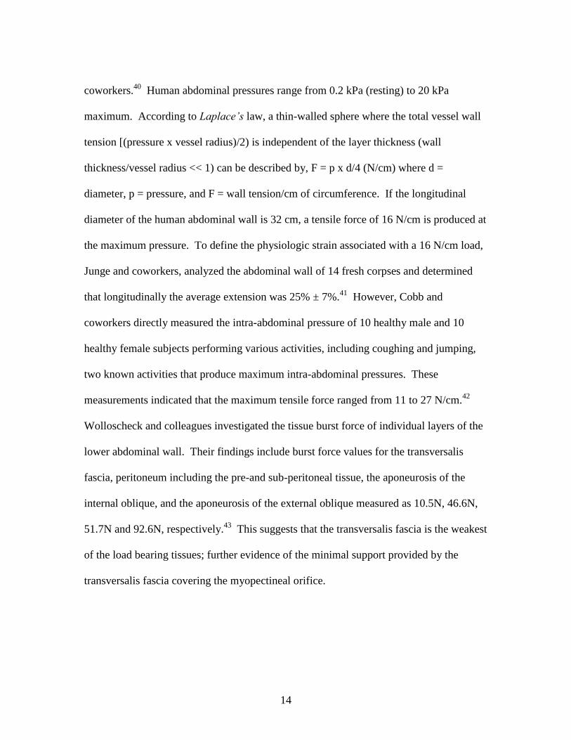
Human abdominal pressures range from 0.2 kPa (resting) to 20 kPa
maximum. According to Laplace’s law, a thin-walled sphere where the total vessel wall
tension [(pressure x vessel radius)/2) is independent of the layer thickness (wall
thickness/vessel radius << 1) can be described by, F = p x d/4 (N/cm) where d =
diameter, p = pressure, and F = wall tension/cm of circumference. If the longitudinal
diameter of the human abdominal wall is 32 cm, a tensile force of 16 N/cm is produced at
the maximum pressure. To define the physiologic strain associated with a 16 N/cm load,
Junge and coworkers, analyzed the abdominal wall of 14 fresh corpses and determined
that longitudinally the average extension was 25% ± 7%.41
However, Cobb and
coworkers directly measured the intra-abdominal pressure of 10 healthy male and 10
healthy female subjects performing various activities, including coughing and jumping,
two known activities that produce maximum intra-abdominal pressures. These
measurements indicated that the maximum tensile force ranged from 11 to 27 N/cm.42
Wolloscheck and colleagues investigated the tissue burst force of individual layers of the
lower abdominal wall. Their findings include burst force values for the transversalis
fascia, peritoneum including the pre-and sub-peritoneal tissue, the aponeurosis of the
internal oblique, and the aponeurosis of the external oblique measured as 10.5N, 46.6N,
51.7N and 92.6N, respectively.43
This suggests that the transversalis fascia is the weakest
of the load bearing tissues; further evidence of the minimal support provided by the
transversalis fascia covering the myopectineal orifice.

15
Hernia Development and Surgical Intervention Using Meshes
Surgical hernia intervention is the most common elective procedure in general
surgery with inguinal hernioplasty performed at the annual rate of 800,000 in the United
States, 200,000 in Germany, 100,000 in France, 80,000 in the United Kingdom, and
12,000 in Finland.44-46
The most important modern advancement in hernia surgery has
been the development of so-called tension-free repair using meshes.47
Anatomical Classification of Hernias
Hernias of the abdominal wall form at areas susceptible to a loss of mechanical
integrity through acquired or congenital pathologies. The weak points of the abdominal
wall are the inguinal, umbilical, and femoral canal regions. From epidemiology data, it is
known that the prevalence rates for abdominal wall hernias are approximately 73%
inguinal, 9.5% umbilical, 6.2% incisional, 2.7% femoral, and 8.6% other types such as
spigelian, hiatal, or epigastric.48
Inguinal hernias are classified as direct or indirect.
Indirect inguinal hernias occur when a visceral sac leaves the abdominal cavity,
enters the deep inguinal ring, and transcends the spermatic cord. The hernial sac
contains peritoneum and viscera such as adipose tissue, intestinal loops, or omentum and
is surrounded by all three fascial coverings of the spermatic cord. The hernia can traverse
the entire inguinal canal and exit through the superficial inguinal ring. In severe cases the
hernial sac enters the scrotum. Indirect inguinal hernias can occur in women, but they are
twenty times more likely in males.

16
Direct inguinal hernias occur when the peritoneum with subperitoneum tissues
and/or abdominal viscera herniate through a weak point in the abdominal wall. The
typical location of direct inguinal hernias is within the confines of the medial triangle of
the myopectineal orifice.35
The hernial sac is formed by distention of the transversalis
fascia lateral to the rectus abdominus muscle and it emerges to reach the superficial
inguinal ring, gaining an outer covering of external spermatic fascia inside or parallel to
that on the cord. It rarely enters into the scrotum. Direct hernias are most common in
elderly men.
Femoral hernias occur within the femoral triangle of the myopectineal orifice and
result from the distension or the rupture of the transversalis fascia.49
It is generally
accepted that they are the result of elevated intra-abdominal pressure and/or an enlarged
femoral ring which facilitates the peritoneum and preperitoneal adipose tissue to protrude
through the femoral ring.50
Subsequently, the hernial sac may travel along the femoral
vessels and settle in the anterior thigh.51
Femoral hernias are more frequent in women
than men (4:1).52
Umbilical hernia prevalence in adults has a female to male ratio of 3:1 with
particular frequency in obese, multiparous women.53
The etiology of umbilical hernias in
adults is believed to initiate during embryonic development through defects in the closure
of the embryo‟s abdominal orifice from which the umbilical cord emerges after the
obliteration of the celomic sac. Over time this weakness manifests itself at the superior
aspect of the umbilicus, becoming susceptible to increased intrabdominal pressure which

17
may drive forward gobbets of preperitoneal fat or an incipient sac. This condition
stretches the fascia before it into a funnel and eventually progresses into a hernia.54
An incisional hernia is one that appears at the site of an incision from a previous
abdominal operation. An incisional hernia can appear within months or take many years
to become evident to the patient. Incisional hernias are sometimes referred to as ventral
hernias, due to their typical position between the rectus abdominal muscles and through
the linea alba, the preferred midline incision used by surgeons for visceral access during
laparotomy.
The Surgical Repair of Hernias
Early attempts at primary intention tissue repairs of groin hernias resulted in
unacceptably high recurrence rates due to dehiscence. The endogenous tissue tension of
the abdominal wall accounted for the poor results in primary repairs. Primary intention
repair is still performed for small defects but is outside of the scope of this review. For
the last three decades, surgical repair with meshes has been considered the gold standard
for any sizable hernia defect.36
Hernia surgical repairs can be divided into two
classifications; (1) open repairs and (2) laparoscopic repairs.
Two commonly used open repairs for inguinal hernioplasty are the Lichtenstein
repair and the giant prosthetic reinforcement of the visceral sac repair. Lichtenstein
repair is the most frequently performed hernia repair worldwide due to its short learning
curve and ease with which general surgeons can obtain acceptable results.44
The
Lichtenstein procedure uses an anterior approach with, most commonly, a polypropylene

18
mesh. The mesh is placed in an onlay position55
and to accommodate the spermatic cord,
a slit is placed in the mesh with the two tails overlapping behind the spermatic cord to
avoid recurrence lateral to the superficial inguinal ring.
Figure 1.4
Mesh placement for the Lichtenstein procedure. A - internal oblique muscle, B -
polypropylene mesh, C - inguinal ligament, D - internal oblique aponeurosis, E - lesser
cord containing the genital nerve, F - spermatic cord55
The giant prosthetic reinforcement of the visceral sac (GPRVS) procedure56,57
was
developed to repair bilateral and complex recurrent inguinal hernias due to its use of a
large mesh that covers both inguinal regions. The GPRVS‟s alternate approach to the
Lichtenstein procedure eliminated the need to operate through distorted anatomy and scar
tissue from the previous surgical site.58
The procedure obtains preperitoneal access
through a midline subumbilical incision allowing access to the preperitoneal space for
blunt dissection. Short term fixation is assured by dissection pocket size, friction, and
19
hydrostatic pressure, all combining to achieve long-term security from tissue ingrowth.59
The result is bilateral mesh coverage within the preperitoneal space of sufficient size to
span all of the potential hernia defects of the myopectineal orifice: indirect, direct, and
femoral.60,61
The effectiveness of the GPRVS procedure was noticed by minimally
invasive surgeons and the concept became the basis for laparoscopic procedures.
Currently, there are two types of laparoscopic hernia repair; the transabdominal
preperitoneal (TAPP) repair and the totally extraperitoneal (TEP) repair,62
with the TAPP
repair being more common.63
The advantage of laparoscopic techniques are decreased
postoperative pain, faster recovery, quicker return to daily activities, coverage of all
potential hernia defects, and minimal fixation required due to assisted stabilization from
intra-abdominal pressure.64
Critics of the process cite increased cost, the use of general
anesthesia, the need for advanced skills that require a long learning curve to master, and
rare but disastrous potential complications.64,65
For the TAPP procedure, the peritoneal
cavity is accessed with an incision with the subsequent creation of a pneumoperitoneum.
Next, a peritoneal incision is made above the hernia defect to enter the preperitoneal
space. Dissection is completed when a pocket of adequate size to cover the myopectineal
orifice is achieved. The mesh is inserted and fixed, typically with staples.66
20
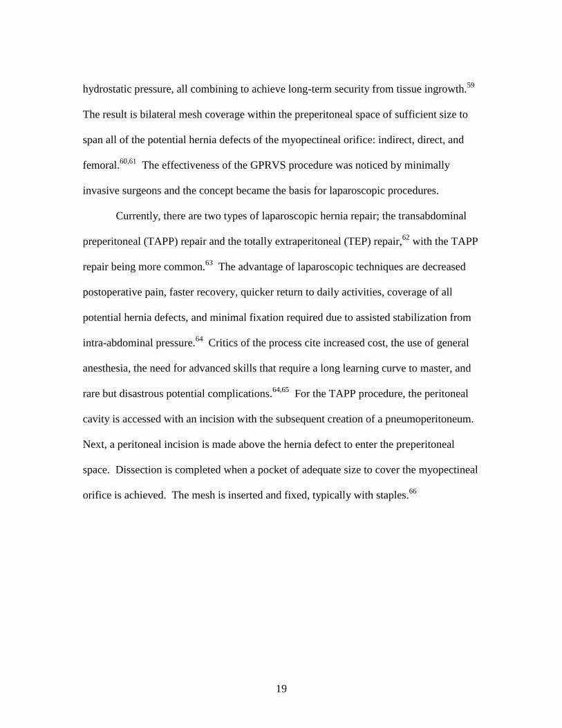
Figure 1.5
The laparoscopic techniques for hernia repair. (A) The transabdominal preperitoneal
(TAPP) technique using preperitoneal mesh placement through a peritoneal incision and
(B) the totally extraperitoneal technique (TEP) using a mesh placement procedure that
does not enter the peritoneal cavity.66
The TEP procedure uses the same preperitoneal mesh placement with the
exception that access to the hernia is created through the preperitoneal space using
dissection to produce a pneumo-preperitoneum.66
The TEP approach is technically more
difficult but it avoids the potential risk of damaging intra-abdominal organs and no
additional incisions are made into the peritoneum.
Complications Associated with Surgical Hernia
Repair Using a Mesh
The introduction of non-absorbable mesh for hernia repair has reduced the
incidence of recurrence, but its presence as a permanent biomaterial has produced several
short-term and long-term complications, all of which have inherent interdependency.

21
Short-term complications include hematoma67
, morbidity from infection68,69
, seroma70-72
,
primary mesh migration73
, wound dehiscence74
, or dislocation and protrusion
75,76 through
the defect site. Long-term complications are of great interest due to their significant
impact on patient quality of life and include neuralgia (chronic pain and paraesthesia),
chronic inflammation, mesh shrinkage, stiffness or reduced abdominal wall mobility,
secondary mesh migration, fistula or mesh adhesion, and recurrence.
Chronic postoperative pain caused by neuralgia is one of the main long-term
complications following inguinal hernia repair and regarded to be the most common
failure of groin hernia surgery.77,78
Recent literature reviews, comparing trials with
follow-ups greater than 3 months, have reported that chronic pain after inguinal hernia
operation may occur in 10-62% of patients, with considerable impact on a patient‟s daily
quality of life.45,79,80
Suggested etiological factors for neuralgia include irritation or
damage to inguinal nerves by incisions or dissections, severance by sutures or tacks, a
chronic inflammatory reaction to the mesh, or entrapment/compression of nerves from
scar tissue development.45,78,81,82
Data suggests that intraoperative nerve damage may be
the most important mechanism for developing chronic pain; however, a nerve lesion is
not the only factor leading to neuralgia, as many more patients have paraesthesia or
sensory abnormalities, rather than pain, after inguinal hernia repair.83
As many as fifty
percent of patients with a large mesh prosthesis complain of paresthesia at the palpable
stiff edges of the mesh.84
These more prevalent sensory abnormalities may originate
from the chronic inflammatory response and subsequent fibrosis and/or shrinkage of the
mesh. Historically, it was believed that mesh repairs reduced chronic pain compared to

22
primary repair but recent long-term investigations suggest that there is no statistical
difference between patient complaints about mesh and primary repair.85
The characteristic chronic inflammatory response to non-absorbable meshes is at
least in part responsible for several additional complications. Mesh shrinkage has been
explored extensively following observations during revision surgeries that significant
folding and shrinking of the mesh was apparent. Mesh size reduction resulting from
myofibroblast activity reduces the pore size and causes buckling and folding of the
prosthesis. Pore size and overall mesh length has been observed to reduce by 20% in
meshes explanted from patients.68
Furthermore, a study conducted by Klinge and
coworkers, using polypropylene mesh on the posterior sheath of the rectus fascia within
the preperitoneal space of dogs, produced an overall reduction in area of 46% within 4
weeks of implantation.86
The extent of mesh shrinkage has been shown to be directly
proportional to the degree of inflammatory response.87
In addition to shrinkage, the inflammatory response to typical mesh biomaterials
results in significant fibrosis that increases the rigidity and stiffness of the abdominal
wall.88
As reviewed by Welty and coworkers, 50% of patients report some form of
physical restriction of the abdominal wall.89
Chronic inflammation is also responsible for
slow and gradual secondary migration of mesh through trans-anatomical planes due to
foreign-body reaction induced erosion of local tissue.68,73
In addition, from a mechanical
point of view, irritation and inflammation from a hard material in contact with soft tissue
can induce erosion in the latter.90
This is especially true in the case of stiff and rigid

23
monofilament polypropylene mesh. Consequently, mesh can enter the abdominal cavity
causing visceral adhesions and/or fistula formation.91
Etiology and Pathology of Hernia Development
Is the development of abdominal wall hernias the result of an anatomical defect or
collagen disease? Historically, hernia genesis was attributed to a mechanical disparity
between visceral pressure and resistance of the structures within the myopectineal orifice.
Which of these factors are significant contributors? Increasingly, hernia etiopathology is
described as a multifactorial process linking an evolutionary anatomical weakness,
predisposed defects, and dynamic factors such as increased abdominal pressure. The
influence of each of these factors in the primary formation and recurrence of hernias is an
area of significant debate.
Mechanisms in the Development of Primary Hernias
Evolution has clearly left human beings with a section of the abdominal wall that
is weaker in comparison to the rest of the abdominal wall: the majority of hernias occur
in the myopectineal orifice of the inguinal region. The thin and weak transversalis fascia
of the groin coupled with the lack of fascial sheath below the arcuate line together form
the argument for an intrinsic defect in the human abdominal wall.92
Many surgeons
believe the transversalis fascia does not even resemble fascia or any tendinous-like
structure; the transversalis fascia is a thin, fibro-membranous peritoneum with markedly
reduced strength as compared with typical fascia.92
The myopectineal orifice is sealed by

24
the transversalis fascia; thus all groin hernias are the result of the displacement of this
fascia by a peritoneal sac.
Hernia development can be congenital in the case of indirect hernias. In this case
a visceral sac leaves the abdominal cavity and transcends the spermatic cord. Congenital
predisposition in males originates during the descent of the fetal testes into the scrotum.
Interruptions in the closure of the deep inguinal ring can develop into a potential defect
later in life.51
Indirect hernias are more common on the right side than left. The right
testicle descends from its position near the kidney into the scrotum after the left testicle
has already completed its descent. The delay in the closure of the deep inguinal ring on
the right side is believed to be responsible for its side-specific hernia predominance.92
Increased intra-abdominal pressure is believed to be a contributing factor in the
pathogenesis of herniation.93
Risk factors include obesity and chronic constipation.
Often hernias are thought to be the result of a single event (e.g. lifting a heavy object) but
in fact repetitive mechanical strain is likely the damaging factor.94
It is possible that
chronic mechanical strain, not prior biologic defects, may induce secondary changes in
structural tissue cellular and molecular function.95
However, increased intra-abdominal
pressure is speculative in nature with no clinical study to confirm its contribution to
hernia formation.93
Furthermore, no adequate animal model exists that can simulate
hernia formation or replicate the increased intra-abdominal pressure from erect posture
gravitational forces on the floor of the abdominal wall.92

25
The Role of Biochemical Mediators and
Collagen in Hernia Formation
Collagen is an active living tissue that is in a constant balanced state of production
and degradation. Because collagen has a long half-life and is the primary biomechanical
strength component in connective tissue, collagen has become the critical component for
investigation in the search for hernia genesis. So-called collagen disease is thought have
two pathologies, (1) a metabolic defect and/or (2) structural abnormalities in any of the
steps related to collagen fiber formation.
Imbalances in the connective tissue metabolic pathways are being investigated to
explain whether the quality of collagen is caused by the presence of destructive enzymes
or by the lack of inhibitors to those destructive enzymes. Collagens are mainly degraded
by matrix metalloproteinases (MMPs) and under normal conditions, are required for the
proper progression and maturation of wound healing.96
MMP-1 and MMP-13 are the
primary collagenases responsible for type I and type III collagen turnover.97
Klinge and
coworkers found that skin of patients with groin hernias had significantly different
upregulated levels of MMP-1 and MMP-13 compared to controls.98
In another study by
Klinge and coworkers, the expression level of MMP-1 in excised hernial sacs of patients
with either direct or indirect hernias was not different compared to that of peritoneum
control samples.99
In addition, MMP-13 was absent from either the hernial sac or control
tissue. Rosch and coworkers analyzed MMP-1 and MMP-13 in cultured fibroblasts from
the skin of patients and concluded that neither was involved in primary inguinal hernia.100
Overall, the implications of MMP-1 and MMP-13 in hernia formation are mixed and
inconclusive.

26
MMP-2 and MMP-9 have been identified as enzymes that break down collagen
Types IV and V as well as gelatin, elastin, fibronectin, and other matrix components.
Both are derived from neutrophils and have been found local to direct hernias but not
indirect hernias.101
In addition, MMP-2 overexpression in fibroblasts from the
transversalis fascia has been observed in young patients with direct hernias but not in
indirect hernia patients.102,103
The increased levels of MMP-2 and MMP-9 have also been
related to diminished levels of tissue inhibitors of matrix metalloproteinases, e.g. TIMP-1
and TIMP-2 are generally linked to elderly patients104
as well as indirect and direct hernia
patients.105
Evidence suggests that MMP-2 and MMP-9 may have a link to direct hernia
formation, especially in elderly patients.
Connective tissue quality is significantly influenced by the quantity and ratio of
Type I/III collagen synthesis and deposition.106
Altered collagen composition with
increased levels of Type III has profound effects on tissue elasticity and resistance to
applied stresses. The genetic expression of Type I or Type III procollagen mRNA affects
the Type I/III ratio. The different genetic expression pathways are poorly understood,
emphasizing that genetic influences on hernia formation are still not clear. In an attempt
to determine whether metabolic or gene transcriptional defects are the primary factors for
an altered Type I/III collagen ratio, studies have been conducted using the skin of
incisional and inguinal hernia patients.98,100,107-109
Each of these studies concluded that a
statistically significant downward shift in the Type I/III ratio was evident in hernia
patients as compared to controls or non-hernia patients, strengthening the position that a
systemic collagen disorder may predispose patients to hernia disease. However, it should

27
be noted that these studies are better characterized as observations of small numbers of
patients and more extensive, prospective studies are required to completely understand if
aberrations within the collagen gene expression profile supports a transcriptional
dysregulation relevant to hernia disease.110
The collagen fibril formation process is critical to collagen quality as fibrils are
the principle source of structural integrity.110
The extent of hydroxylation of lysine and
glycosylation of hydroxylysine provides the intermolecular and intramolecular covalent
bonds responsible for the bulk strength of mature collagen.111
During remodeling and
maturation, collagen fibers increase in diameter reflecting the change in the ratio of
Types I and III collagen.107
Differences in the rectus sheath ultrastructure of hernia
patients compared to non-hernia patients have been the target of several studies.112,113
Results indicated that for hernia patients, the ultrastructure of the rectus sheath had
irregularly arranged fibers that exhibited disturbed collagen hydroxylation, fibers with
caliber differences, and fewer collagen fibers that were replaced with ground substance.
Unfortunately, not enough is known about the structural and molecular-cell basis of
collagen fibrillogenesis to confidently define it as the etiology of hernia disease.110
Causes of Recurrent Hernias
In approximately 60% of all excised meshes, recurrence is the reason for
extraction.114
The recurrence of hernia repairs has frustrated surgeons for many years,
especially incisional hernia recurrence with rates of 11-15% within the first year and a
doubling of the high initial rates within the first nine years.115
The stated causes of

28
recurrence include stress applied to the wound prior to the development of mechanical
integrity, shear stresses at the margins of the mesh during collagen maturation, collagen
metabolism disorders, infection, and surgical technical errors. Immediate gross failure in
most cases is attributed to surgeon technical failure or infection, while longer term (> 3
months) failure stems primarily from abnormal wound healing such as varied collagen
metabolism and the progress of acute wound disruptions into symptomatic failures.
There is evidence that hernia recurrence of mesh-repaired laparotomies is the
result of external stresses applied to the wound site prior to the development of tissue
integration and wound strength (first 2-3 weeks post insult). As reviewed by Franz, one
prospective study of primary repaired incisional hernias found that the total rate of acute
wound disruption was about 11% at post-operative day 30 with the majority (94%) later
developing into incisional hernias.95
Primary repaired incisional hernias fail by wound
dehiscence from sutures pulling through the wound edges. Similarly, mesh acute wound
failures also occur from stressed suture lines at the margins of the mesh creating mesh-
fascial dehiscence. The result of the failure is a loss in tension applied across the wound.
The loss of mechanical load signaling may impair fibroblast biology which promotes
subsequent collagen abnormalities leading to the high rate of recurrent incisional hernia
formation.95
Recurrent hernias develop 99% of the time at the margins of the implanted
mesh.87,114,116-118
Owing to the significant strength of most meshes, central mesh ruptures
are a documented but extremely rare occurrence.119,120
The nonphysiologically low
stretching capability of the mesh/tissue complex contrasts with the highly elastic

29
abdominal wall resulting in shear forces at the margins of the mesh. These forces
overstress developing and maturing collagen resulting in recurrence at the margins of the
mesh.84
Incisional hernias are also being investigated as an abnormal wound healing
response with an inability to produce abundant, quality, strong collagen. As with primary
hernias, metabolic factors are being investigated; however, more evidence supports
collagenase as a central agent involved with the development of incisional hernias when
compared to primary hernia formation.97
Though this may be, it is hard to accept
metabolic factors as the primary pathway to recurrent hernia when the majority of
patients do not have a history of wound healing defects and do not express any defects in
organs local to the surgical site or the vascular system.
Knitting Technologies and Their Relevance to
the Properties of Surgical Meshes
Knit textile structures come in two general forms; (1) weft knit and (2) warp knit.
Mesh construction can be dramatically different between the two structures, but the
concept of using intermeshing loops of yarn is the same for both. The properties of a
knitted structure are largely dependent on the interaction of each stitch with its
neighboring stitches in the course and wale directions. The course is the cross direction
to the fabric production, while the wale is the parallel direction to the fabric production.

30
Weft Knit Mesh
The simple weft knit structure is formed by loops created by needles knitting fiber
across the width of the fabric with each loop being created by pulling it through the
previous loop in the same direction (Figure 1.6a). Needle movements are simply up and
down and are controlled by a cam. When the needles are in the up position, each weft
fiber is fed at an angle to the direction of fabric formation, single or multiple ends of fiber
can be fed into the mesh at one time but each end knits the same pattern with no overlap
or variation.
Looking at a cross-sectional view of the structure, all the loops are bent into the
third dimension due to the manner in which loops are pulled through each other. This
configuration results in an unbalanced structure which causes the mesh to curl at the
edges in an attempt to release some of the strains within the loops.121
The simplicity of
the weft knit structure with minimal cross-over points between courses and wales makes
it strong in burst strength, extremely porous, highly drapable, and highly elastic.
However, the greatest obstacle for the weft knit construction in use for medical
applications is that they easily run from their edges, especially when cut.

31
Figure 1.6
Knitted fabric from (a) a simple weft and (b) a single guide bar, half-tricot warp knit
construction.122
Warp Knit Mesh
Warp knitting differs from weft knitting in that loops are formed by every needle
in the needle bar during the same knitting cycle from series of warp fibers that are fed
parallel to the direction of mesh formation (Figure 1.6b). The so-called warp, is a sheet
of fiber with ends wrapped concentrically in parallel on a cylindrical beam prepared in a
creel prior to being mounted on the knitting machine. The warp fibers lap the needle bar
simultaneously by a series of guide bars that move through and then laterally to the
needle bar. Lateral movements include underlaps which are produced on the mesh
production side of the needle bar and overlap on the alternate side. The number of guide
bars is pattern-specific but generally varies between one and four.
Warp knit meshes provide versatile pattern selection, control of elasticity,
unraveling resistance, good drapability, control of porosity, good dimensional stability,

32
and high strength. Medical meshes used in hernia applications are constructed in such
configurations as the queenscord, tricot lapping, atlas lapping, and the sand-fly net.123
Mesh Properties as Determined from Knitting
Type and Construction
The elasticity and strength of a weft knit mesh is controlled by the number of
needles per inch, i.e. gauge, and the stitch length, which controls the number of courses
per inch. The gauge is typically set by the machine configuration leaving the stitch
length as the only adjustable variable. Although elasticity and strength can be somewhat
adjusted, there is no structural variability to further modify the weft knit properties.
The variability available with warp knitting allows extensive modulation of the
physical and mechanical properties. To produce elastic or stretchable structures, the
mesh must be designed with either (1) short underlaps or (2) an open mesh
construction.124
The most basic example of short underlaps is a single guide bar, one
needle underlap and one needle overlap, commonly referred to as a half-tricot stitch.
Increases in the underlap movement reduce extensibility and increase stability. The half
tricot pattern produces a dimensionally stretchable mesh with relatively small pores. To
produce larger openings in the mesh, loops can be formed continuously on the same
needle such that there are no connections by adjacent wales (underlaps) followed by a
lateral interlace after a specific number of courses.125
Different size and shape openings
can be produced with symmetrical pores when knit using partial threading of two guide
bars that are lapping in opposition. Another significantly less extensible open work mesh
that can be created is a lay-in mesh, i.e. a marquisette construction. Lay-in constructions,

33
at the most basic level, consist of a chain stitch, or series of stitches from one needle in
the course direction, joined together by laying-in yarn between the loops. The lay-in yarn
does not form a stitch because it does not have lateral movement during the overlap, only
during the underlap. As such, the fiber does not enter the hook of the needle but rather is
captured within the loops of the chain stitch.
Figure 1.7
Examples of (a) a short underlap mesh (half-tricot), (b) an open work mesh (sand-fly net),
and (c) a lay-in mesh (3-guide bar marquisette).122,125
Stabilization of Mesh Constructions using Heat Setting
Mesh dimensional stability and refinement of the fiber microstructure
morphology are accomplished using a heat setting process. The effect of heat setting is
affected by the temperature, time, and tension applied during the process with the most
significant factor being temperature.126
Fiber morphology is altered by relieving induced
stress from orientation and increasing the fibers entropy. As a result, stresses in the

34
construction of the mesh are relaxed improving dimensional stability, heat stability from
entropy driven shrinkage, handling characteristics, and in many cases the softness of the
mesh.
Meshes as Biomaterials
An ideal mesh material should be strong, compliant, non-allergenic, sterilizable,
chemically inert to the biologic environment, resistant to infection, dimensionally and
chemically stable in vivo, non-carcinogenic, cost effective, and should stimulate
fibroblastic activity for optimum incorporation into the tissue with no long-term reaction.
Clinically Relevant Mesh Materials
Each material used for the construction of hernia meshes has its advantages;
however, all of them reveal some disadvantages. Currently there is no ideal mesh
material, but polypropylene is most common regardless of certain drawbacks.
Polypropylene (PP)
Polypropylene is a linear aliphatic hydrocarbon with a methyl group attached to
alternate carbon atoms on the chain backbone (-C3H6-). As a result it is nonpolar and
highly hydrophobic. The addition of the methyl group has many physico-mechanical,
structural, and chemical implications. Physico-mechanically the methyl group stiffens
the chain by reduced molecular mobility from this relatively bulky side group.
Polypropylene derives its mechanical properties from chain entanglement and

35
intermolecular secondary bond forces (van der Waals-London forces) from induced
dipole hydrogen bonds between chains.127
Structurally the methyl group produces
tacticity with medical grade PP being highly isotactic with approximately 95%
crystallinity. All of the methyl groups are configured to one side of the carbon backbone
in the isotactic form, thereby creating a regular structure and facilitating crystallinity.
Steric hindrance from the methyl group forms crystals in helical conformations, unlike
the planar zigzag form of polyethylene. The presence of the methyl group also affects its
chemical nature, providing a tertiary carbon atom that is susceptible to oxidation and
chain scission.128
However, overall PP is considered to be an inert, stable material that
provides an adequate service life in vivo as a mesh material.
Polyethylene Terephthalate (PET)
Polyethylene terephthalate was introduced as a mesh material for hernia repair
more than 30 years ago and continues to be used today, although its use is limited in most
countries, with the exception of France.129
PET is a heterochain linear aromatic polymer
with repeat units comprised of ester groups on either side of its ring and two ethylene
moieties added to one side (-C10H8O4-). As such, the polymer is slightly polar, more
hydrophilic, and hygroscopic than homochain hydrocarbon polymers. The characteristic
feature of PET is its two ester linkages in the backbone of the polymer chain. Chemically
the ester groups create chemically liable sites that are susceptible to hydrolysis and thus
chain scission. However, the local hydrophobic moieties slow this reaction considerably.
Physico-mechanically the stronger dipole-dipole type van der Waals-London forces

36
between adjacent carbonyl groups contribute to its high strength characteristics.127
Structurally PET is a semicrystalline polymer with crystallization kinetics such that the
level of crystallinity can be controlled through thermal history and strain-induced
crystallization. The second most important characteristic is its aromatic ring which adds
stiffness to the backbone of the chain enhancing its physical and mechanical properties.
Accordingly, PET is typically processed into fine multifilaments rather than
monofilament fibers in surgical meshes.
Expanded Polytetrafluoroethylene (ePTFE)
Expanded polytetrafluoroethylene is not a widely used material for hernia meshes.
Its application is generally limited to surgical situations where visceral adhesion is of
major concern. Polytetrafluoroethylene (PTFE) is a linear homochain polymer
constructed of a carbon backbone saturated with fluorine atoms (-CF2-). The
characteristic feature of PTFE is its inert nature, due to the extreme stability of the
carbon-fluorine bond. PTFE is highly crystalline; however, although the structure is
similar to polyethylene, crystallites are not formed in the planar zigzag form. Instead, a
modified form of a twisted zigzag is created due to steric hindrance from the increased
size of the fluorine atom compared to hydrogen.130
The intermolecular attraction
between PTFE molecules is very small and thus its bulk properties do not possess the
high rigidity and tensile strength associated with other hernia mesh materials. Also, the
physical form of PTFE is the exception to the typical fiber form of hernia mesh materials.
The morphological difference is due to the high crystalline melting point of PTFE being
37
very close to its degradation temperature leaving no melt processing window.
Accordingly, ePTFE is manufactured by stretching and sintering a solid melt-extruded
sheet while at the same time producing a node-fibril structure that results in micropores.
This process gives rise to the “expanded” precursor designation.
Partially Absorbable Mesh Constructions
The intent of partially absorbable mesh constructions is to reduce the amount of
biomaterial, e.g. polypropylene, in an attempt to reduce the foreign body response.
Meshes constructed from a combination of a 10/90 copolymer of poly(L-lactide-co-
glycolide) and polypropylene have become the most common form of partially
absorbable mesh and are the most investigated. Theoretically the reduced level of
resident mass results in less fibrosis, structural changes that result in larger pores, and less
chronic inflammation.131
Partially absorbable meshes are constructed by plying the
different filaments together and then knitting the plied yarn to produce a mesh with
approximately 50% absorbable polymer.84
The high polyglycolide copolymer is a linear,
aliphatic polyester comprised of a single ester and ethylene group (-CH2COO-). The
ester group in the chain backbone is readily hydrolyzed due to its somewhat hydrophilic
nature and a lack of any side chain structures that provide steric hindrance. Polyglycolide
produces relatively high levels of crystallinity from planar zigzag crystallites which give
the material excellent stiffness. Mechanical properties are typically reduced about 50%
in 2-3 weeks with complete absorption within 90 days.

38
Mesh Characteristics Pertinent to Biocompatibility
The design characteristics of meshes include construction, fiber form, fiber
surface, and bulk chemistry. Collectively these characteristics significantly influence the
biocompatibility of a mesh and its mechanical suitability for a particular application.
However, although the design characteristics of meshes have produced significant debate
with regard to their respective influences, no study has been completed which isolates
each characteristic. For example, an in vivo study that compares the same construction
and yarn form and differing chemistry does not exist. To date, studies have been
conducted using commercially available meshes, and each has a different construction,
fiber form, and fiber chemistry making it difficult to isolate the influence of individual
mesh design variables. However, observations about mesh design variables have
provided insight into their general influence on biocompatibility.
Mesh Construction
Mesh construction can be extensively varied and has implications on pore size,
area weight, drape, extensibility, and strength, all which clinically translate into surgical
handling characteristics, anatomical conformability, foreign body reaction, and the
mechanical, cellular, and extra cellular matrix characteristics of the mesh/tissue complex.
The porosity of a mesh is best described as the amount of open space in a unit
area of mesh. However, this description does not provide a complete picture as the
dimensions/area of individual pores, the distance between pores, and the size and quantity
of interstitial pores, are also contributing factors to in vivo performance. Porosity is a

39
rarely measured characteristic. Recently, a study using digital imaging was conducted in
order to better characterize the overall porosity and the distribution of different pore sizes
for clinically relevant meshes.132
The porosity of meshes is a primary determinant for
tissue response, with pore size implicated in affecting long-term abdominal wall mobility.
It has been suggested that pores smaller than 1mm lead to extensive inflammation and
fibrosis, resulting in a bridging of collagen between adjacent pores.84,114,133
Ultimately
this occurrence produces a dense, continuous outer fibrotic capsule covering the whole
mesh. Several investigations using a rat134-136
and a porcine137
animal model have
concluded that larger pores result in increased abdominal wall mobility due to reduced
fibrotic bridging. In addition, the absence of a complete capsule covering the mesh
facilitates improved fluid transport through the mesh, as well as improved vascularization
and organization of connective tissue.138
Based on increasing evidence, porosity is a key
factor in the incorporation of the mesh into the surrounding tissue, and thus an important
prerequisite to its biocompatibility.
Area weight, measured as the mass per area (g/m2), is a determination of the total
amount of biomaterial implanted for a given area. Theoretically, lower area weights
induce a milder foreign body reaction, improved abdominal wall compliance, less
contraction or shrinkage, and allow better tissue incorporation; as a result, the use of
lighter weight or partially absorbable meshes has been investigated to improve hernia
repair outcomes. However, the available data is contradictory and controversial. The
outcomes from partially absorbable meshes are mixed. Early investigations in a rat
animal model indicated long-term decreased inflammation as a result of the long-term

40
decreased polypropylene content.136,139
However, Weyhe and coworkers have
investigated the changes in foreign body reaction in both a rat animal model140
and in
vitro141,142
and determined that simple reduction of the mesh mass was not the main
determinant of biocompatibility; rather, pore size and material composition were better
indicators. Clinical trials have produced conflicting outcomes as well. Several studies
have found no significant differences between typical polypropylene meshes and partially
absorbable meshes in multicenter studies using Lichtenstein hernioplasty.143,144
Conze
and coworkers found similar outcomes when comparing partially absorbable and standard
polypropylene meshes; however, partially absorbable mesh had a trend toward increased
hernia recurrence.145
Other authors have reported improvements in some aspects of pain
and discomfort using partially absorbable meshes,146
but in addition to less chronic pain,
an increase in recurrence has also been reported.147
In a recent review of current
randomized controlled trials and retrospective studies, partially absorbable meshes seem
to have some advantage with respect to post-operative pain and foreign body sensations,
but their use is associated with increased recurrence rates.148
The movement toward the
use of lower weight meshes has shown researchers and clinicians that long-term, lower
area weight meshes appear to reduce some complications but at the cost of an apparent
increase in recurrence.
The mesh construction in vivo can influence the mechanical properties of the
mesh/tissue complex. When a mesh is stressed, the mesh filaments show minimal if any
elasticity, while the mesh itself produces extensive elongation from geometric
deformation within the pores perpendicular to the applied stress. Thus, the elastic

41
characteristics of a mesh and the ability to match those of the natural abdominal wall are
predominately influenced by construction. In a study conducted by Greca and coworkers
a polypropylene light weight, macroporous mesh (19 g/m2) was compared to a typical so
called „heavy weight‟ mesh (85 g/m2) in the repair a full-thickness abdominal wall defect
in a dog animal model. Although the heavy weight mesh had 3.6 times the initial burst
strength of the light weight mesh, after 90 days in vivo the mesh/tissue complex for the
light weight mesh produced marginally greater average burst strengths than the heavy
weight mesh.149
The authors attributed the increased strength to a higher concentration of
mature type I collagen developed around the light weight mesh. The mechanical
characteristics of the mesh construction are important factors, as the maturation of the
mesh/tissue complex is a critical indicator of biocompatibility.
The strength of a mesh is not only characterized by yarn diameter or denier,
number of yarns, and tenacity of the yarn, but construction also affects the burst strength.
The nature and extent of yarn looping within the mesh construction affects the burst
strength due to stress concentrations. For a given mesh construction, stronger mesh yarn
does not always translate linearly to increased mesh burst strength. Construction can play
a limiting role in the strength of the construct.
Type of Yarn
Monofilament-based meshes have marked stiffness, whereas multifilament
meshes have improved softness, less surface texture, and better drape characteristics for
adaptation to anatomical curvatures. Multifilaments physically have a pronounced

42
increase in surface area, which influences their biocompatibility. In vivo testing in a rat
animal model has suggested a more intense acute inflammatory response and increased
fibrosis to multifilament yarn than monofilament yarn.150-152
The authors attributed the
upregulated response to the increased tissue/biomaterial surface contact area. Patients
implanted with either multifilament or monofilament polypropylene meshes for inguinal
hernioplasty were investigated for inflammatory response differences. Blood samples
were collected before surgery and up to 168 hours post-surgery, and were analyzed for
pro-inflammatory mediators. Results indicated a more intense acute inflammatory
response to the multifilament mesh.153
The increased response may be in part the result
of the increased adsorption of host proteins to the implant, which in turn triggers the
increased activation of inflammatory cells. Long-term, multifilaments have not been
identified as triggering an increased level of chronic inflammation as compared with
monofilaments, in fact, more leukocytes and larger multinucleated giant cells have been
observed to be associated with monofilament meshes.154
Multifilament based mesh constructions have been implicated as producing a
higher incidence of infection. Amid suggested that the infiltration and proliferation of
bacteria within multifilament meshes is due to interstices or pores that are less than 10
microns.68
The result is the development of infection by the housing of bacteria which
have sizes averaging 1 micron and the exclusion of macrophages and neutrophils of 10-
15 microns in size. In fact, infection associated with multifilament meshes often
necessitates the removal of the mesh to alleviate the problem, while infection associated
with many monofilament meshes can be treated with antibiotics and drainage of the

43
sepsis.155
However, a rat study to investigate Amid‟s claim determined that pore size
alone does not predict infection and suggested that collagen fibers and macrophages
penetrated and surrounded multifilament fibers at two weeks.154
Pore size alone is not
the only variable in infection prevention. The ability of a mesh to resist infection is also a
function of the surface area available for bacterial attachment, biomaterial composition
and hydrophobicity, and the interaction with the local host tissue defenses.156,157
Infection always starts with bacterial adhesion, which is influenced by the surface
roughness, hydrophobicity, and the material‟s inherent ability to generate electro-static
forces or an electric charge that transfers between the polymer surface and the bacterial
wall, resulting in attraction.158,159
Klinge and coworkers determined that the surface area
of multifilament meshes was increased by a factor of at least 1.57 in comparison to
monofilament, thus providing significantly more area for bacterial adhesion. The authors
indicated that the increased surface area associated with multifilaments was the primary
reason for the persistence of bacteria in the implant bed.160
In the same study, rats were
implanted with monofilament and multifilament meshes which were inoculated with
Staphylococcus aureus prior to implantation. No increased infection rates were observed
between the two fiber forms as compared to controls. Overall, it should be noted that
both monofilament and multifilament yarn forms have produced good clinical
biocompatibility with long-term experiences.

44
Yarn Surface and Bulk Chemistry
The surface and bulk properties of a yarn can be dramatically different. Surfaces
are physically unique environments with varied mechanical, morphological, barrier, and
electrical properties. The surface of a biomaterial is the interfacial transition between
bulk chemistry and the in vivo environment. The surface provides the only direct
chemical or biophysical interaction with the biologic environment. Surface properties are
influenced by unsaturated secondary bonds of atoms comprising the surface and their
interaction with opposing surfaces or molecules.161
For the polymers used in meshes,
their hydrophobic or hydrophilic nature is derived from unassociated polar and nonpolar
groups at the surface. Bulk properties, on the other hand, arise from composition and
morphology of everything below a few atoms deep of the surface, determining such
properties as elastic modulus, toughness, yield strength, and hardness.
Chemical degradation that results in reduced physical and mechanical properties
is the primary obstacle to long-term mesh stability. Due to the foreign body reaction, the
mesh material is continuously exposed to super oxides. As previously discussed,
polypropylene is susceptible to oxidative degradation. Continuous exposure of
polypropylene to these oxidants can lead to chain scission, production of radicals, and
degradation to the surface and bulk chemical structure. In one study, 85% of explanted
polypropylene meshes exhibited cracks, surface roughness, and peeling of the surface
from oxidation.162
Surface oxidative degradation of polypropylene has been shown to
result in bulk property changes such as a loss of mass, a lowering the glass transition and
melt temperatures, diminished molecular mobility, and a reduction in yield stress and

45
elongation at break.163-166
Moreover, both polypropylene and polyethylene terephthalate
have been shown to absorb squalene, palmitic acid, and, in some cases cholesterol.127
These small organic molecules may act as plasticizers and further decrease yield stress.
The bulk degradation and fracture of polyethylene terephthalate yarn from hydrolysis has
been realized for vascular grafts and meshes.167-169
In the future, it is possible that
eventual bulk degradation will be realized in polypropylene, which will limit its service
life, especially in young patients for whom the mesh is expected to hold for several
decades. Remarkably these finding are in contradiction to the widely accepted belief that
non-absorbable mesh materials, particularly polypropylene, are stable and inert.
Biocompatibility – Meshes and the Biologic Environment
The word biocompatibility is used extensively, yet a great deal of uncertainty
exists about what it actually means and about the mechanisms that collectively control
the concept. Several definitions have been proposed, with none gaining widespread
acceptance. Historically, the biocompatibility of long-term implanted devices has been
graded on their ability to be chemically and biologically inert and do no harm to the
surrounding host tissue. As knowledge of the biologic environment has grown, more
emphasis is placed on functionally stimulating or avoiding specific cellular or tissue
responses. A recent re-definition of biocompatibility has been suggested by Williams:
“Biocompatibility refers to the ability of a biomaterial to perform its desired function
with respect to a medical therapy, without eliciting any undesirable local or systemic
effects in the recipient or beneficiary of that therapy, but generating the most appropriate

46
beneficial cellular or tissue response in that specific situation, and optimizing the
clinically relevant performance of that therapy”.170
The following sections explore the
current status of mesh biocompatibility.
Early Phases of Wound Healing and Mesh Integration
The early phases of normal wound healing include hemostasis and acute
inflammation characterized by fibrin clot formation, bacterial clearing, and wound
debridement followed by proliferation, which includes the formation of granulation tissue
and wound contraction. Granulation tissue is made up of a cellular, randomly ordered
extracellular matrix containing new blood vessels from angiogenesis. When the acute
inflammation phase does not resolve in a timely manner it is said to enter a state of
chronic inflammation.
Acute and Chronic Inflammation – Responses to Meshes
Tissue disruption and bleeding during mesh implantation results in fibrin clot
formation and a burst of inflammatory cytokines that attract monocytes/macrophages,
polymorphonuclear cells, and lymphocytes. From the instant that the mesh is placed in
situ, surface protein adsorption is initiated followed by a reorganization of the protein
layer as described by the Vroman effect. Resident tissue cells such as mast cells and
macrophages become activated and respond to the biomaterial. It is believed that these
phagocytes attach and interact with the adsorbed proteins rather than with the material
itself.114
Phagocytes attempt but are unable to remove the mesh due to its size and

47
relatively inert nature. As a result, the healing response moves into the chronic
inflammation phase due to the continued presence of the mesh. Consequently, the
proliferation phase initiates, but with the continued presence of inflammatory cells.171
Within the first few hours, neutrophil activity is initiated with bloodborne
neutrophils entering the local tissue by diapedesis. For the ensuing weeks the presence of
the mesh stimulates neutrophil activity beyond the time of its normal resolution. Blood
samples from mesh and primary repaired hernia patients, up to 168 hours postoperative,
suggest the presence of a mesh significantly increases the neutrophil count.153
Neutrophil
activity is detrimental to the healing wound site because of the excessive generation of
matrix metalloproteinases favoring the degradation of local and newly formed tissue.172
Neutrophil activity investigated in a rat animal model using a simulated mesh hernia
repair peaked in activity at 3 days and steadily decreased in numbers until 14 days.173
An
investigation by Rosch and coworkers using a rat animal model determined that, in the
early phases, the wound area contains predominately macrophages with persistent T-cell
activity that lasts through 90 days.174
In addition, within the first week, mast cell activity
is elevated. The mast cell‟s role in inflammation is mostly credited to the recruitment of
inflammatory cells from the release of their granular products including histamine.
Furthermore, mast cell release of histamine facilitates increased blood flow and cell
infiltration through dilation of arterials and increased permeability of venules.175
The
continuous cytokine generation, which is said to peak between 7 and 14 days, progresses
the wound healing response into the proliferation phase as the host tissue attempts to
isolate the mesh through encapsulation.

48
Proliferation – Tissue Integration and Collagen Development
The proliferation phase is primarily characterized by the increased presence of
fibroblasts that produce significant amounts of extracellular matrix with maximum
deposition at 2-3 weeks. Consequently, the bulk of the collagen is deposited in the
proliferation stage; however, even under normal wound healing conditions, high quality
collagen is not formed until later in the maturation phase. Wound mechanical integrity
begins to develop as the level of crosslinking increases. Unfortunately, the overlap of the
acute wound healing trajectory may further delay the recovery of wound tensile
strength.176
Wound inflammation is primarily a protective response; studies suggest that
the mechanisms used to destroy bacteria and remove debris delay tissue repair.177
Fascial
tissues within the abdominal wall have been shown to develop strength faster than dermal
wounds. Fibroblasts extracted from rat fascial wounds show enhanced cell proliferation
and increased wound collagen deposition compared to dermal fibroblasts.178
Mechanisms for accelerated fascial healing include earlier activation of fascial fibroblasts
and earlier induction of collagen synthesis compared to dermal wounds.179
Macrophages
play a fundamental role in the process of extracellular matrix development through direct
or indirect fibroblast signaling. Results from animal studies have suggested that the
absence of macrophages results in defective scar formation.180
On the other hand,
increases in the time and intensity of inflammation are associated with increased levels of
scarring181
; however, the amount of collagen present at the wound site is not a good
indicator of mechanical integrity. The bulk of extracellular matrix production occurs
during the proliferation stage, but this does not represent the time at which the

49
extracellular matrix is complete. Significant changes in orientation and conformation of
fiber bundles have yet to occur during the remodeling and maturation stage in order to
develop quality collagen.
Development of Vascular Structures – Angiogenesis
Wound repair and normal healing depends on an adequate arterial circulation
supplying the newly forming tissue with oxygen. Angiogenesis begins during the
proliferation phase. Vasculature in the wound periphery develop small buds or sprouts
that grow into the fibrin/fibronectin-rich wound clot and, within a few days, organize into
a microvascular network within the granulation tissue. Several factors including vascular
endothelial growth factor (VEGF), basic fibroblast growth factor (bFGF), platelet-derived
growth factor (PDGF), and transforming growth factor (TGF-β) induce angiogenesis,182
which is then directed to the wound area by low oxygen tension gradients and elevated
lactic acid levels.183
The development of new blood vessels is critical since healing will
not proceed unless new, functioning blood vessels supply oxygen and nutrients to the
developing tissue and remove metabolic waste. However, the distribution of oxygen by
neovascularization goes beyond nutritional support. There are several posttranslational
steps in collagen synthesis that are oxygen dependent and responsible for the
development of tensile strength in healed wounds.184,185
At the end of the proliferative
phase, cellular activity is decreasing and there is less need for a rich vascular supply.
Consequently, some capillaries aggregate into larger vessels but most of the recently
formed blood vessels quickly involute through apoptosis of endothelial cells. Overall,

50
wound angiogenesis represents a response to coagulation, inflammation, and the
temporary increased metabolic need of the wound area that is well beyond the capacity of
the vessels that once fed the site.186
Laschke and coworkers187
developed a novel, quantitative method of investigating
angiogenesis for mesh implantation in a rat animal model and found that by day 3 of
implantation the protrusion of capillary buds and sprouts had originated from the host
microvasculature. Until day 10, the sprouts interconnected to form loops and a new
microvascular network. By day 14, the vascular ingrowth was complete with venular
diameters and volumetric blood flow comparable to those in the host tissue, distant from
the mesh. In a study to investigate the effect of yarn diameter on tissue response, fibrotic
capsule thickness around individual yarns was reduced when vascular structures were
observed close to the filament.188
The finding is consistent with the expectation that
tissue response is more favorable if nutrients are available locally. Additionally, vascular
constructs in close proximity to the mesh improve the cellular response to infection. For
other implanted, mesh-like constructions such as vascular grafts, investigations have
found that the potent cytokines secreted by chronically active macrophages are inhibitors
to angiogenesis.189
This suggests that intense acute inflammation may inhibit
angiogenesis. In conclusion, the extensive vascularization of an implanted mesh is
imperative to the optimal integration and resultant mechanical properties of the
mesh/tissue complex.

51
Contraction of the Mesh/Tissue Complex
Collagen deposition is accompanied by wound contraction as a natural
phenomenon that decreases the area of the wound defect. For mesh hernia repair, it is an
undesired consequence that initiates during the second week and is associated with
recurrence, migration, and pain.190,191
The etiology is largely unknown but it has been
suggested that during proliferative scars the impaired activity of myofibroblasts renders
them unable to control normal fibrillar arrangement; in addition, excessive production of
TGF-β during chronic inflammation increases contraction.192
Early and complete
integration of the mesh into the surrounding tissue may decrease mesh shrinkage. In a
swine study to investigate the association between tissue ingrowth and mesh contraction,
suture detachment from fixation points was observed, indicating that shrinkage occurred
before the mesh had time to integrate into the tissue.190
On the other hand, meshes that
exhibited strong integration into the surrounding tissue exhibited the least amount of
contraction. As reviewed by Garcia-Urena, in a study comparing mesh shrinkage with or
without fixation after 90 days, the meshes in the fixation group shrank less and retained
their original shape indicating the importance of mesh stability to shrinkage.191
As
previously indicated, the extent of mesh shrinkage has been shown to be directly
proportional to the degree of inflammatory response.87
It is also known that extensive
inflammation delays the proliferative phase of tissue deposition, which may reduce the
integration of the mesh into the surrounding tissue. Together, the physical consequences
of delayed tissue ingrowth due to inflammation and inadequate mesh stability have
potential contributing roles in mesh shrinkage.

52
Meshes and the Immune Response
The immune system protects the body from potentially harmful substances by
recognizing and responding to antigens or non-self molecules. For meshes, the immune
response is a rarely investigated topic because synthetic materials are not considered
immunogenic. However, fluids from the in vivo environment can facilitate mesh yarn
swelling which results in the leaching of low molecular weight particles such as
impurities, antioxidants, plasticizers, and unreacted monomer. These particles
themselves are not immunogenic, but if they covalently bond to a secretory protein or
protein on a cell surface they become haptens and the complex is then recognized as an
antigen by the immune system. Another potential pathway is from activated
macrophages, at or near the surface of the polymer, which release highly reactive radicals
that damage the polymer surface and create degradation products that can act as haptens
to adsorbed proteins.193,194
Depending on the physicochemical properties of the implant
surface and type of absorbed proteins, the rate of degradation and thus the immune
response will be variable.114
The immunologic response triggers the activation of
macrophages, which respond by releasing pro-inflammatory chemokines that attract
additional immune cells. Furthermore, immune cells under typical wound healing
conditions have a role in wound resolution. It has been demonstrated that T lymphocytes
have an active role in cytokine production at the wound site and are essential to a
successful healing process.195
T-lymphocytes have been shown to have a nonspecific
reaction against biomaterials with influences in macrophage recruitment, formation of
giant cells, and the phagocytosing activity of macrophages and giant cells.174
On the

53
other hand, there is no evidence that B lymphocytes play a significant role in wound
healing.196
In all, the adaptive immune response to synthetic meshes is thought to be
minimal, and only a small part of the overall acute inflammatory response. A more
significant nonspecific or innate role is played by T-lymphocytes, with influences over
macrophage activity.
Mesh/Tissue Complex Stability and Applied Tension
The surgical repair of hernias with mesh results in a lower level of tension applied
to the wound. Unlike primary repair, the edges of the hernia are not completely
approximated; instead, the mesh is sutured in place with the defect forming what is
known as a hernia ring that is spanned on all sides by the mesh. The mesh then becomes
the scaffold, allowing extracellular matrix to develop within and around the hernia ring.
The reduced wound tension of mesh repairs compared to primary repair has increased the
clinical use of meshes for incisional hernia repair from 35% in 1987 to 66% in 1999.197
This shift is due to an observed reduction in recurrence, which has been attributed to
lower levels of wound tension. The most common cause of wound failure in primary
repair is dehiscence, from the tearing of suture through the fascia. Although less
common, the mechanism exists for meshes because of the endogenous tension of the
tissue being repaired. However, early biomechanical wound disruption for meshes
occurs almost exclusively at the suture line located at the margins of the mesh. For
example, during the first few weeks after hernia repair, minimal extracellular matrix
integrity has developed, and applied loads are concentrated at the points of suture

54
attachment.198
Concurrently, recovering surgical patients return to physical activity,
placing increased loads across the acute wound during its weakest phase.39,199
Therefore,
suture integrity at the margins of the mesh must exclusively resist the applied stresses.
Failure to resist the applied stress results in mesh-fascial dehiscence.
The general clinical consensus is that wound tension should be minimized during
early post-operative periods.200
Burger and coworkers, using computed tomography
scans in a retrospective study, determined that, although incisional hernias in some cases
are not realized until several months or years after surgery, the hernia process starts
during the first postoperative month with observable separation of the rectus abdominal
muscles.201
These defects may initiate small and asymptomatic, but can steadily increase
in size, eventually allowing the protrusion of abdominal contents and visible bulging.
DuBay and coworkers designed a rat surgical model that produces acute fascial
separation following the rapid dissolution of cat gut suture.202
The ensuing incisional
hernias have a well defined hernia ring, protruding hernia sac, and visceral adhesions,
providing all of the characteristics that clinically develop in humans. Following mesh
repair of the induced hernia, animals were evaluated on post operative days 7, 14, 28, and
60 for the development of recurrent incisional hernias. It was determined that 16% of the
total 21% recurrences occurred by post operative day 7.202
The authors concluded that
recurrent incisional hernia formation is an early postoperative occurrence.
In addition to recurrence, wound biomechanical disruptions can affect
angiogenesis. During the early stages of angiogenesis, capillary sprouts lack full
thickness which renders them delicate and easily disrupted. Budding vessels are so

55
fragile that collagen fibers must surround them to prevent rupturing when blood pressure
is imposed by arterial inflow.182
Immobilization of the granulation tissue is essential
through the proliferation phase to permit vascular regrowth and prevent
microhemorrhages.7 The prevention of these microhemorrhages facilitates the
progression of the wound healing process without the release of additional pro-
inflammatory cytokines. Wound stability during the early postoperative period is critical
to preventing wound disruptions at the suture line that can evolve into recurrences and is
critical for optimal wound site vascularization.
Advanced Phases of Wound Healing and Maturation
The so-called maturation phase of wound healing is characterized by a decrease in
cell density and metabolic activity followed by balanced collagen degradation and
deposition process whereby the wound site is remodeled through collagen fiber bundle
organization based on chemical and mechanical stimulation.
The Long-Term Foreign Body Response to Meshes
All meshes demonstrate a chronic, persistent foreign body reaction. The long-
term tissue reaction at the interface to the mesh is independent of implantation time and
characterized by many macrophages, granulomas, and foreign body giant cells.203
Aggregated, activated, and frustrated macrophages lead to macrophage fusion and the
formation of foreign body giant cells on the surface of implanted biomaterials.193
Foreign
body giant cells are the predominant cell type of the long-term foreign body reaction,

56
with their numbers more than doubling from 2 months to 6 months around polypropylene
filaments in a swine animal study.204
This process initiates early and persists for years,
being observed in explanted meshes 15 years after patient implantation.205
Patients with
polyethylene terephthalate mesh hernia repairs were biopsied during later operations to
study the tissue response.206
At 16 months, a layer of foreign body giant cells developed
around the yarns, macrophages collected in an intermediate layer of mature granuloma
with fine fibrillar collagen, and a denser outer border of collagen bundles aligned along
stress lines and was populated by fibroblasts. The partial volume of cells and physical
nature of the foreign body response has been reported to be affected by the type of mesh
material. Polyethylene terephthalate induced tissue reactions show comparatively little
inflammation but have heavily macrophage populated granulomas, whereas
polypropylene shows an increased amount of inflammation and connective tissue.203
It
should be noted that the yarn form, construction, pore sizes, and so on, are different
between typical polyethylene terephthalate and polypropylene meshes; other factors
beyond material type likely influence long-term foreign body reaction. Altogether, non-
absorbable mesh causes a persistent, long-term inflammatory reaction at the interface
between polymer yarn and host tissue; the reaction is comprised mostly of foreign body
giant cells and macrophages within granulation tissue, which is surrounded by a collagen
capsule.

57
Wound Maturation – Collagen Reorganization and Crosslinking
The wound site extracellular matrix surrounding the mesh progresses from a
blood-based provisional matrix of fibrin clot and serum protein deposition (inflammation
phase), to a loose, disorganized, weak collagen network that, after several weeks begins
to crosslink and develop strength (proliferation), to finally a complete replacement and
reorganization of the collagen fibers and fiber bundles and established integrity of the
local tissue. During remodeling, collagen turnover allows the randomly deposited scar
tissue to be rearranged and restore some level of functionality. To achieve this goal,
quality collagen is produced by adequate synthesis, degradation, crosslinking, and
remodeling of collagen fibrils in response to mechanical stimulation.
The goal of hernioplasty should be to restore the morphology and functions of the
abdominal wall such that the prosthesis provides a substitute with characteristics closest
to the tissue‟s normal function, with a low elastic modulus more relevant to performance
than the relative strength of the mesh.207
Increasingly, it is being recognized that the
growth and remodeling of fibrotic tissue that supports mechanical loads is governed by
the same principles as Wolffs‟ Law for bone.171
A lack of stress produces atrophy while
excessive stress results in necrosis. Ideally, low forces produce extracellular matrix
distention, providing endogenous stress that fibroblasts maintain under tensional
homeostasis.208
Meshes begin to significantly decrease the mobility of the abdominal
wall 2-3 weeks after implantation from the induction of the scar plate.208
In the uniaxial
direction, typical meshes have low initial elastic modulus due to deformations within the
pores. However, biaxially, with fixation on all sides, current meshes have a high elastic

58
modulus with very low elongation even at maximum physiologic conditions.
Consequently, the mesh absorbs most of the mechanical load and the stress-deprived
extracellular matrix will not efficiently remodel or mature. Matching of the implant
load/extensional characteristics to the tissue should create a fibrotic capsule that is
substantial and strong, with elastic properties that more closely match those of the
surrounding tissue. Furthermore, when two contacting materials have marked differences
in their elastic moduli, the result is high shear stress concentrations at the interface.171
This difference is evidenced in reports of collagen fibers, which orientate along stress
lines, aligning parallel to individual filaments of yarn and around the outer fibrotic
capsule around the mesh203,205
, but with little or no orientation reported within the pores.
Relative motion at the mechanical interface may also be responsible in part for the
foreign body response to meshes. Increased shear stresses and a lack of mechanical
stability at the interface may cause load mediated cell necrosis and general irritation to
the tissue stimulating inflammation.171
A mesh/tissue complex that has firm attachment and close matching of the mesh
and tissue elastic moduli is critical to the long-term mesh/tissue complex mechanical
properties and the level of foreign body response to the mesh. Mechanical stimulation
significantly influences the remodeling of the mesh/tissue complex and the development
of proper physiology.

59
New Opportunities Based On Currently Unmet Needs
Since the development of absorbable sutures over three decades ago, there has
been interest in using absorbable multifilament yarn for constructing absorbable meshes.
However, this interest has been limited by unsuccessful attempts to repair load bearing
soft tissues such as abdominal wall hernia repairs. Meshes constructed of only fast
absorbing polyglycolide or 90/10 poly(glycolide-co-lactide) provide inadequate strength
beyond three to four weeks of breaking strength retention. In addition, development of
meshes constructed from relatively slow degrading high-lactide yarn has generated little
to no interest. This situation has left the majority of soft tissue repair load bearing
applications to be filled by non-absorbable materials, which suffer distinctly from
undesirable features associated, in part, with their inability to (1) possess short-term
stiffness to facilitate tissue stability during the development of wound strength; (2)
gradually transfer the perceived mechanical loads as the wound is building mechanical
integrity; (3) provide compliance with load transfer to the remodeling and maturing
mesh/tissue complex; and (4) minimize the likelihood of long-term complications with
their degradation and absorption at the conclusion of their intended functional
performance. Wound healing is a dynamic process that results in different criteria at
different phases for the optimal development of the mesh/tissue complex. Current non-
absorbable or partially absorbable meshes may not provide adequate early stability and
then a sufficient level of long-term mechanical stimulation to the remodeling and
maturing collagen.

60
Absorbable medical meshes in the form of multicomponent systems possessing
different degradation rates can produce modulated mechanical, chemical, and physical
properties which individually or collectively may improve the wound healing process.
Figure 1.8 illustrates the characteristics of a multicomponent mesh that has two different
strength profiles compared to the wound strength profile and typical phases of wound
healing. Each characteristic or phase is indicated with anticipated time intervals.
Figure 1.8
The modulated mechanical characteristics of a multicomponent mesh superimposed
with the wound healing response.

61
The mesh wound stability phase continues through the inflammation and
proliferation phases. Early stiffness of the mesh may facilitate uninterrupted tissue
integration and angiogenesis, while reducing the risk of recurrence from applied wound
stresses prior to the development of wound strength. In addition, the added stiffness and
stability may resist and/or minimize the wound contraction process. As the wound
develops load bearing capability, stress is slowly transferred as the fast degrading
component loses strength. Once the fast degrading component of the mesh is removed,
the long lasting component is well encapsulated in the extracellular matrix. The mesh is
positioned in a relaxed configuration such that the newly deposited collagen becomes
load bearing and tensional homeostasis is returned to the abdominal wall. Over the
ensuing months the remodeling/maturing process of collagen degradation and synthesis
adapts the tissue to the loading conditions. Finally, the slow degrading component loses
its mechanical integrity by hydrolysis and is metabolized, leaving the wound site without
the continuous foreign body response. Ultimately, the abdominal wall is left with a
functional, sustainable layer of tissue that seals the defect area preventing future hernia
formation.

62
References
1. Dee KC, Puleo DA. An introduction to tissue-biomaterials interactions. Hoboken,
NJ: Wiley-Liss; 2002.
2. Mulder GD, Brazinsky BA, Harding KG, Agren MS. Factors influencing wound
healing. In: Leaper DJ, Harding KG, editors. Wound biology and management.
Oxford, England: Oxford University Press; 1998. p 52-69.
3. Stadelmann WK, Digenis AG, Tobin GR. Physiology and healing dynamics of
chronic cutaneous wounds. Am J Surg 1998;176(2A Suppl):26S-38S.
4. Paul M. Wound healing - aiming for perfect skin regeneration. Science
1997;276:75-81.
5. Witte MB, Barbul A. General principles of wound healing. Surg Clin North Am
1997;77(3):509-28.
6. Lorenz HP, Longaker MT. Wounds: biology, pathology, and management. In:
Norton JA, Bollinger RR, Chang AE, Lowry SF, Mulvihill SJ, Pass HI,
Thompson RW, editors. Surgery: Basic science and clinical evidence. New York,
NY: Springer-Verlag; 2003. p 77-88.
7. Hardy MA. The biology of scar formation. Phys Ther 1989;69(12):1014-24.
8. Yang GP, Lim IJ, Phan TT, Lorenz HP, Longaker MT. From scarless fetal
wounds to keloids: molecular studies in wound healing. Wound Repair Regen
2003;11(6):411-8.
9. Silver FH, Christiansen DL, Snowhill PB, Chen Y. Transition from viscous to
elastic-based dependency of mechanical properties of self-assembled type I
collagen fibers. J Appl Polym Sci 2000;79:134-42.
10. Bailey AJ, Paul RG, Knott L. Mechanisms of maturation and ageing of collagen.
Mech Ageing Dev 1998;106(1-2):1-56.
11. Fratzl P, Misof K, Zizak I, Rapp G, Amenitsch H, Bernstorff S. Fibrillar structure
and mechanical properties of collagen. J Struct Biol 1998;122(1-2):119-22.
12. Silver FH, Ebrahimi A, Snowhill PB. Viscoelastic properties of self-assembled
type I collagen fibers: molecular basis of elastic and viscous behaviors. Connect
Tissue Res 2002;43(4):569-80.

63
13. Misof K, Rapp G, Fratzl P. A new molecular model for collagen elasticity based
on synchrotron X-ray scattering evidence. Biophys J 1997;72(3):1376-81.
14. Puxkandl R, Zizak I, Paris O, Keckes J, Tesch W, Bernstorff S, Purslow P, Fratzl
P. Viscoelastic properties of collagen: synchrotron radiation investigations and
structural model. Philos Trans R Soc Lond B Biol Sci 2002;357(1418):191-7.
15. Bonifasi-Lista C, Lake SP, Small MS, Weiss JA. Viscoelastic properties of the
human medial collateral ligament under longitudinal, transverse and shear
loading. J Orthop Res 2005;23(1):67-76.
16. Benjamin M, Hillen B. Mechanical influences on cells, tissues and organs -
'Mechanical Morphogenesis'. Eur J Morphol 2003;41(1):3-7.
17. Screen HR, Shelton JC, Bader DL, Lee DA. Cyclic tensile strain upregulates
collagen synthesis in isolated tendon fascicles. Biochem Biophys Res Commun
2005;336(2):424-9.
18. Webb K, Hitchcock RW, Smeal RM, Li W, Gray SD, Tresco PA. Cyclic strain
increases fibroblast proliferation, matrix accumulation, and elastic modulus of
fibroblast-seeded polyurethane constructs. J Biomech 2006;39(6):1136-44.
19. Yang G, Crawford RC, Wang JH. Proliferation and collagen production of human
patellar tendon fibroblasts in response to cyclic uniaxial stretching in serum-free
conditions. J Biomech 2004;37(10):1543-50.
20. Park SA, Kim IA, Lee YJ, Shin JW, Kim CR, Kim JK, Yang YI. Biological
responses of ligament fibroblasts and gene expression profiling on micropatterned
silicone substrates subjected to mechanical stimuli. J Biosci Bioeng
2006;102(5):402-12.
21. Eckes B, Zweers MC, Zhang ZG, Hallinger R, Mauch C, Aumailley M, Krieg T.
Mechanical tension and integrin alpha 2 beta 1 regulate fibroblast functions. J
Investig Dermatol Symp Proc 2006;11(1):66-72.
22. Bride J, Viennet C, Lucarz-Bietry A, Humbert P. Indication of fibroblast
apoptosis during the maturation of disc-shaped mechanically stressed collagen
lattices. Arch Dermatol Res 2004;295(8-9):312-7.
23. Puk CK, Miller DJ, Gamradt S, Wu BM, McAllister DR. The effects of short-
term stimulation on fibroblast spreading in an in vitro 3D system. J Biomed Mater
Res A 2006;76(4):665-73.

64
24. Eastwood M, Mudera VC, McGrouther DA, Brown RA. Effect of precise
mechanical loading on fibroblast populated collagen lattices: morphological
changes. Cell Motil Cytoskeleton 1998;40(1):13-21.
25. Prajapati RT, Chavally-Mis B, Herbage D, Eastwood M, Brown RA. Mechanical
loading regulates protease production by fibroblasts in three-dimensional collagen
substrates. Wound Repair Regen 2000;8(3):226-37.
26. Yasuda K, Hayashi K. Changes in biomechanical properties of tendons and
ligaments from joint disuse. Osteoarthritis Cartilage 1999;7(1):122-9.
27. Hannafin JA, Arnoczky SP, Hoonjan A, Torzilli PA. Effect of stress deprivation
and cyclic tensile loading on the material and morphologic properties of canine
flexor digitorum profundus tendon: an in vitro study. J Orthop Res
1995;13(6):907-14.
28. Eckes B, Kessler D, Aumailley M, Krieg T. Interactions of fibroblasts with the
extracellular matrix: implications for the understanding of fibrosis. Springer
Semin Immunopathol 1999;21(4):415-29.
29. Li F, Li B, Wang QM, Wang JH. Cell shape regulates collagen type I expression
in human tendon fibroblasts. Cell Motil Cytoskeleton 2008;65(4):332-41.
30. Hinz B, Mastrangelo D, Iselin CE, Chaponnier C, Gabbiani G. Mechanical
tension controls granulation tissue contractile activity and myofibroblast
differentiation. Am J Pathol 2001;159(3):1009-20.
31. Faryniarz DA, Chaponnier C, Gabbiani G, Yannas IV, Spector M. Myofibroblasts
in the healing lapine medial collateral ligament: possible mechanisms of
contraction. J Orthop Res 1996;14(2):228-37.
32. Mirastschijski U, Haaksma CJ, Tomasek JJ, Agren MS. Matrix metalloproteinase
inhibitor GM 6001 attenuates keratinocyte migration, contraction and
myofibroblast formation in skin wounds. Exp Cell Res 2004;299(2):465-75.
33. Grinnell F, Zhu M, Carlson MA, Abrams JM. Release of mechanical tension
triggers apoptosis of human fibroblasts in a model of regressing granulation
tissue. Exp Cell Res 1999;248(2):608-19.
34. Burgess LP, Morin GV, Rand M, Vossoughi J, Hollinger JO. Wound healing.
Relationship of wound closing tension to scar width in rats. Arch Otolaryngol
Head Neck Surg 1990;116(7):798-802.
65
35. Fagan SP, Awad SS. Abdominal wall anatomy: the key to a successful inguinal
hernia repair. Am J Surg 2004;188(6A Suppl):3S-8S.
36. Park AE, Roth JS, Kavic SM. Abdominal wall hernia. Curr Probl Surg
2006;43(5):326-75.
37. Annibali R, Fitzgibbons RJ, Quinn T. Surgical anatomy of the inguinal region
from a laparoscopic perspective. In: Bendavid R, Abrahamson J, Arregui M,
Flament J, Phillips E, editors. Abdominal Wall Hernias: Priciples and
Management. New York, NY: Springer-Verlag; 2001.
38. Flament J, Avisse C, Delattre J. Anatomy of the abdominal wall. In: Bendavid R,
Abrahamson J, Arregui M, Flament J, Phillips E, editors. Abdominal Wall
Hernias: Principles and Management. New York, NY: Springer-Verlag; 2001. p
39-63.
39. Peiper C, Junge K, Prescher A, Stumpf M, Schumpelick V. Abdominal
musculature and the transversalis fascia: an anatomical viewpoint. Hernia
2004;8(4):376-80.
40. Klinge U, Klosterhalfen B, Conze J, Limberg W, Obolenski B, Ottinger AP,
Schumpelick V. Modified mesh for hernia repair that is adapted to the physiology
of the abdominal wall. Eur J Surg 1998;164(12):951-60.
41. Junge K, Klinge U, Prescher A, Giboni P, Niewiera M, Schumpelick V. Elasticity
of the anterior abdominal wall and impact for reparation of incisional hernias
using mesh implants. Hernia 2001;5(3):113-8.
42. Cobb WS, Burns JM, Kercher KW, Matthews BD, James Norton H, Todd
Heniford B. Normal intraabdominal pressure in healthy adults. J Surg Res
2005;129(2):231-5.
43. Wolloscheck T, Gaumann A, Terzic A, Heintz A, Junginger T, Konerding MA.
Inguinal hernia: measurement of the biomechanics of the lower abdominal wall
and the inguinal canal. Hernia 2004;8(3):233-41.
44. Bhattacharjee P. Surgical options in inguinal hernia: Which is the best. Ind J Surg
2006;68(4):191-200.
45. Paajanen H. A single-surgeon randomized trial comparing three composite
meshes on chronic pain after Lichtenstein hernia repair in local anesthesia. Hernia
2007;11(4):335-9.

66
46. Schwab R, Klinge U. Principle actions for re-currences. In: Schumpelick V,
Fitzgibbons RJ, editors. Recurrent Hernia. Berlin, Germany: Springer-Verlag;
2007.
47. Awad SS, Fagan SP. Current approaches to inguinal hernia repair. Am J Surg
2004;188(6A Suppl):9S-16S.
48. Weber A, Garteiz D, Valencia S. Epidemiology of inguinal hernia: a useful aid for
adequate surgical decisions. In: Bendavid R, Abrahamson J, Arregui M, Flament
J, Phillips E, editors. Abdominal Wall Hernias: Principles and Management. New
York, NY: Springer-Verlag; 2001.
49. Palot J, Avisse C. Open techniques of femoral hernia repair. In: Bendavid R,
Abrahamson J, Arregui M, Flament J, Phillips E, editors. Abdominal Wall
Hernias: Priniciples and Management. New York, NY: Springer-Verlag; 2001.
50. Temiz A, Akcora B, Temiz M, Canbolant E. A rare and frequently unrecognised
pathology in children: femoral hernia. Hernia 2008;12(5):553-56.
51. Bax T, Sheppard BC, Crass RA. Surgical options in the management of groin
hernias. Am Fam Physician 1999;59(1):143-56.
52. Rodrigues AJ, Rodrigues C, Plopper C, Terra RM. Do the dimensions of the
femoral canal play a role in the genesis of femoral hernia? Hernia 2000;4:45-51.
53. Velasco M, Garcia-Urena MA, Hidalgo M, Vega V, Carnero FJ. Current concepts
on adult umbilical hernia. Hernia 1999;4:233-39.
54. Deysine M. Umbilical hernias. In: Bendavid R, Abrahamson J, Arregui M,
Flament J, Phillips E, editors. Abdominal Wall Hernias: Principles and
Management. New York, NY: Springer-Verlag; 2001.
55. Amid PK. Lichtenstein tension-free hernioplasty: its inception, evolution, and
principles. Hernia 2004;8(1):1-7.
56. Wantz GE, Fischer E. Unilateral giant prosthetic reinforcement of the visceral
sac: preperitoneal hernioplasties with Dacron. In: Bendavid R, Abrahamson J,
Arregui M, Flament J, Phillips E, editors. Abdominal Wall Hernias: Principles
and Management. New York, NY: Springer-Verlag; 2001.
57. Lowham AS, Filipi CJ, Fitzgibbons RJ, Jr., Stoppa R, Wantz GE, Felix EL,
Crafton WB. Mechanisms of hernia recurrence after preperitoneal mesh repair.
Traditional and laparoscopic. Ann Surg 1997;225(4):422-31.

67
58. Kurzer M, Belsham PA, Kark AE. Prospective study of open preperitoneal mesh
repair for recurrent inguinal hernia. Br J Surg 2002;89(1):90-3.
59. Kugel RD. Minimally invasive, nonlaparoscopic, preperitoneal, and sutureless,
inguinal herniorrhaphy. Am J Surg 1999;178(4):298-302.
60. Muldoon RL, Marchant K, Johnson DD, Yoder GG, Read RC, Hauer-Jensen M.
Lichtenstein vs anterior preperitoneal prosthetic mesh placement in open inguinal
hernia repair: a prospective, randomized trial. Hernia 2004;8(2):98-103.
61. Sinha R, Sharma N, Dhobal D, Joshi M. Laparoscopic total extraperitoneal repair
versus anterior prepertitoneal repair for inguinal hernia. Hernia 2006;10:187-91.
62. Ridings P, Evans DS. The transabdominal pre-peritoneal (TAPP) inguinal hernia
repair: a trip along the learning curve. J R Coll Surg Edinb 2000;45(1):29-32.
63. Horgan LF, Shelton JC, O'Riordan DC, Moore DP, Winslet MC, Davidson BR.
Strengths and weaknesses of laparoscopic and open mesh inguinal hernia repair: a
randomized controlled experimental study. Br J Surg 1996;83(10):1463-7.
64. Fenoglio ME, Bermas HR, Haun WE, Moore JT. Inguinal hernia repair: results
using an open preperitoneal approach. Hernia 2005;9(2):160-1.
65. Nyhus LM. Herniology 1948-1998: Evolution toward excellence. Hernia
1998;2:1-5.
66. Liem MS, van Vroonhoven TJ. Laparoscopic inguinal hernia repair. Br J Surg
1996;83(9):1197-1204.
67. Beltran MA, Cruces KS. Outcomes of Lichtenstein hernioplasty for primary and
recurrent inguinal hernia. World J Surg 2006;30(12):2281-7; discussion 2288-9.
68. Amid PK. Classification of biomaterials and their related complications in
abdominal wall hernia surgery. Hernia 1997;1:15-21.
69. Mann DV, Prout J, Havranek E, Gould S, Darzi A. Late-onset deep prosthetic
infection following mesh repair of inguinal hernia. Am J Surg 1998;176(1):12-4.
70. Susmallian S, Gewurtz G, Ezri T, Charuzi I. Seroma after laparoscopic repair of
hernia with PTFE patch: is it really a complication? Hernia 2001;5(3):139-41.
71. Tsereteli Z, Ramshaw B, Ramaswamy A. Chronic posterior seroma with
neoperitoneum following laparoscopic ventral hernia repair: treatment algorithm.
Hernia 2008;12(4):363-66.

68
72. Mayagoitia JC, Almaraz A, Diaz C. Two cases of cystic seroma following mesh
incisional hernia repair. Hernia 2006;10(1):83-6.
73. Agrawal A, Avill R. Mesh migration following repair of inguinal hernia: a case
report and review of literature. Hernia 2006;10(1):79-82.
74. van't Riet M, de Vos van Steenwijk PJ, Bonjer HJ, Steyerberg EW, Jeekel J. Mesh
repair for postoperative wound dehiscence in the presence of infection: is
absorbable mesh safer than non-absorbable mesh? Hernia 2007;11(5):409-13.
75. Binnebosel M, Rosch R, Junge K, Flanagan TC, Schwab R, Schumpelick V,
Klinge U. Biomechanical analyses of overlap and mesh dislocation in an
incisional hernia model in vitro. Surgery 2007;142(3):365-71.
76. Kes E, Lange J, Bonjer J, Stoeckart R, Mulder P, Snijders C, Kleinrensink G.
Protrusion of prosthetic meshes in repair of inguinal hernias. Surgery
2004;135(2):163-70.
77. Staal E, Nienhuijs SW, Keemers-Gels ME, Rosman C, Strobbe LJ. The impact of
pain on daily activities following open mesh inguinal hernia repair. Hernia
2008;12(2):153-7.
78. Palumbo P, Minicucci A, Nasti AG, Simonelli I, Vietri F, Angelici AM.
Treatment for persistent chronic neuralgia after inguinal hernioplasty. Hernia
2007;11(6):527-31.
79. Nienhuijs S, Staal E, Strobbe L, Rosman C, Groenewoud H, Bleichrodt R.
Chronic pain after mesh repair of inguinal hernia: a systematic review. Am J Surg
2007;194(3):394-400.
80. Hompes R, Vansteenkiste F, Pottel H, Devriendt D, Van Rooy F. Chronic pain
after Kugel inguinal hernia repair. Hernia 2008;12(2):127-32.
81. Aasvang E, Kehlet H. Surgical management of chronic pain after inguinal hernia
repair. Br J Surg 2005;92(7):795-801.
82. Ndiaye A, Diop M, Ndoye JM, Konate I, Ndiaye AI, Mane L, Nazarian S, Dia A.
Anatomical basis of neuropathies and damage to the ilioinguinal nerve during
repairs of groin hernias. (about 100 dissections). Surg Radiol Anat
2007;29(8):675-81.
83. Aasvang E, Kehlet H. Chronic postoperative pain: the case of inguinal
herniorrhaphy. Br J Anaesth 2005;95(1):69-76.
69
84. Doctor H. Evaluation of various prosthetic materials and newer meshes for hernia
repairs. J Min Access Surg 2006;2(3):110-16.
85. Poobalan AS, Bruce J, King PM, Chambers WA, Krukowski ZH, Smith WC.
Chronic pain and quality of life following open inguinal hernia repair. Br J Surg
2001;88(8):1122-6.
86. Klinge U, Klosterhalfen B, Muller M, Ottinger AP, Schumpelick V. Shrinking of
polypropylene mesh in vivo: an experimental study in dogs. Eur J Surg
1998;164(12):965-9.
87. Kockerling C, Schug-Pass C. Recurrence and mesh material. In: Schumpelick V,
Fitzgibbons RJ, editors. Recurrent Hernia. Berlin, Germany: Springer-Verlag;
2007.
88. Champault G, Bernard C, Rizk N, Polliand C. Inguinal hernia repair: the choice of
prosthesis outweighs that of technique. Hernia 2007;11(2):125-8.
89. Welty G, Klinge U, Klosterhalfen B, Kasperk R, Schumpelick V. Functional
impairment and complaints following incisional hernia repair with different
polypropylene meshes. Hernia 2001;5(3):142-7.
90. Klinge U, Krones CJ. Can we be sure that the meshes do improve the recurrence
rates? Hernia 2005;9:1-2.
91. Felemovicius I, Bonsack ME, Hagerman G, Delaney JP. Prevention of adhesions
to polypropylene mesh. J Am Coll Surg 2004;198(4):543-8.
92. McArdle G. Is inguinal hernia a defect in human evolution and would this insight
improve concepts for methods of surgical repair? Clin Anat 1997;10(1):47-55.
93. Rosch R, Junge K, Lynen P, Mertens P, R., Klinge U, Schumpelick V. Hernia - A
collagen disease? Eur Surg 2003;35:11-15.
94. Kang SK, Burnett CA, Freund E, Sestito J. Hernia: is it a work-related condition?
Am J Ind Med 1999;36(6):638-44.
95. Franz MG. The biology of hernias and the abdominal wall. Hernia
2006;10(6):462-71.
96. Rosch R, Junge K, Binnebosel M, Bertram P, Klinge U, Schumpelick V.
Laparoscopy and collagen metabolism. Hernia 2006;10(6):507-10.

70
97. Donahue TR, Hiatt JR, Busuttil RW. Collagenase and surgical disease. Hernia
2006;10(6):478-85.
98. Klinge U, Zheng H, Si Z, Schumpelick V, Bhardwaj RS, Muys L, Klosterhalfen
B. Expression of the extracellular matrix proteins collagen I, collagen III and
fibronectin and matrix metalloproteinase-1 and -13 in the skin of patients with
inguinal hernia. Eur Surg Res 1999;31(6):480-90.
99. Klinge U, Zheng H, Si ZY, Schumpelick V, Bhardwaj R, Klosterhalfen B.
Synthesis of type I and III collagen, expression of fibronectin and matrix
metalloproteinases-1 and -13 in hernial sac of patients with inguinal hernia. Int J
Surg Investig 1999;1(3):219-27.
100. Rosch R, Klinge U, Si Z, Junge K, Klosterhalfen B, Schumpelick V. A role for
the collagen I/III and MMP-1/-13 genes in primary inguinal hernia? BMC Med
Genet 2002;3:2.
101. Bendavid R. The unified theory of hernia formation. Hernia 2004;8(3):171-6.
102. Bellon JM, Bujan J, Honduvilla NG, Jurado F, Gimeno MJ, Turnay J, Olmo N,
Lizarbe MA. Study of biochemical substrate and role of metalloproteinases in
fascia transversalis from hernial processes. Eur J Clin Invest 1997;27(6):510-6.
103. Bellon JM, Bajo A, Ga-Honduvilla N, Gimeno MJ, Pascual G, Guerrero A, Bujan
J. Fibroblasts from the transversalis fascia of young patients with direct inguinal
hernias show constitutive MMP-2 overexpression. Ann Surg 2001;233(2):287-91.
104. Ashcroft GS, Herrick SE, Tarnuzzer RW, Horan MA, Schultz GS, Ferguson MW.
Human ageing impairs injury-induced in vivo expression of tissue inhibitor of
matrix metalloproteinases (TIMP)-1 and -2 proteins and mRNA. J Pathol
1997;183(2):169-76.
105. Abci I, Bilgi S, Altan A. Role of TIMP-2 in fascia transversalis on development
of inguinal hernias. J Invest Surg 2005;18(3):123-8.
106. Junge K, Klinge U, Rosch R, Mertens PR, Kirch J, Klosterhalfen B, Lynen P,
Schumpelick V. Decreased collagen type I/III ratio in patients with recurring
hernia after implantation of alloplastic prostheses. Langenbecks Arch Surg
2004;389(1):17-22.
107. Si Z, Bhardwaj R, Rosch R, Mertens PR, Klosterhalfen B, Klinge U. Impaired
balance of type I and type III procollagen mRNA in cultured fibroblasts of
patients with incisional hernia. Surgery 2002;131(3):324-31.
71
108. Friedman DW, Boyd CD, Norton P, Greco RS, Boyarsky AH, Mackenzie JW,
Deak SB. Increases in type III collagen gene expression and protein synthesis in
patients with inguinal hernias. Ann Surg 1993;218(6):754-60.
109. Zheng H, Si Z, Kasperk R, Bhardwaj RS, Schumpelick V, Klinge U,
Klosterhalfen B. Recurrent inguinal hernia: disease of the collagen matrix? World
J Surg 2002;26(4):401-8.
110. Lynen Jansen P, Klinge U, Mertens PR. Hernia disease and collagen gene
regulation: are there clues for intervention? Hernia 2006;10(6):486-91.
111. El Sherif A, Yano F, Mittal S, Filipi CJ. Collagen metabolism and recurrent hiatal
hernia: cause and effect? Hernia 2006;10(6):511-20.
112. Jansen PL, Mertens Pr P, Klinge U, Schumpelick V. The biology of hernia
formation. Surgery 2004;136(1):1-4.
113. Szczesny W, Cerkaska K, Tretyn A, Dabrowiecki S. Etiology of inguinal hernia:
ultrastructure of rectus sheath revisited. Hernia 2006;10(3):266-71.
114. Klosterhalfen B, Junge K, Klinge U. The lightweight and large porous mesh
concept for hernia repair. Expert Rev Med Devices 2005;2(1):103-17.
115. Hollinsky C, Sandberg S. Measurement of the tensile strength of the ventral
abdominal wall in comparison with scar tissue. Clin Biomech (Bristol, Avon)
2007;22(1):88-92.
116. Junge K, Klinge U, Klosterhalfen B, Rosch R, Stumpf M, Schumpelick V.
Review of wound healing with reference to an unrepairable abdominal hernia. Eur
J Surg 2002;168(2):67-73.
117. Schumpelick V, Klinge U, Rosch R, Junge K. Light weight meshes in incisional
hernia repair. J Min Access Surg 2006;2(3):pNA.
118. Klinge U, Marcel B, Rosch R, Peter M. Hernia recurrence as a problem of biology
and collagen. J Min Access Surg 2006;2(3):151-54.
119. Schippers E. Central mesh rupture - myth or real concern? In: Schumpelick V,
Fitzgibbons RJ, editors. Recurrent Hernia. Berlin, Germany: Springer-Verlag;
2007.
120. Langer C, Neufang T, Kley C, Liersch T, Becker H. Central mesh recurrence after
incisional hernia repair with Marlex--are the meshes strong enough? Hernia
2001;5(3):164-7.

72
121. Matic-Leigh SR. Dimensional stability, aesthetic and mechanical properties of
micro-fiber blended knitted fabrics. Nat Tex Cent Quart Rep 1993;April-June:13-
5.
122. Spencer D. Weft and warp knitting. In Knitting Technology: A comprehensive
handbook and practical guide, 3rd Edition. Cambridge, England: Woodhead
Publishing Limited; 2001.
123. Soares BM, King MW, Marois Y, Guidoin RG, Laroche G, Charara J, Girard JF.
In vitro characterization of a fluoropassivated gelatin-impregnated polyester mesh
for hernia repair. J Biomed Mater Res 1996;32(2):259-70.
124. Raz S. The karl mayer guide to technical textiles: Karl Mayer
Textilmaschinenfabrik, GmbH; 1998.
125. NoAuthor. Open work fabrics. American LIBA literature:48-58.
126. Gaoming J, Xuhong M, Dajun L. Process of warp knitting mesh for hernia repair
and its mechanical properties. Fibres Text East Eur 2005;13(3(51)):44-6.
127. Bracco P, Brunella V, Trossarelli L, Coda A, Botto-Micca F. Comparison of
polypropylene and polyethylene terephthalate (Dacron) meshes for abdominal
wall hernia repair: a chemical and morphological study. Hernia 2005;9(1):51-5.
128. Brydson J. Aliphatic polyolefins other than polyethylene, and diene rubbers. In
Plastic Materials, 7th Edition. Oxford, England: Butterworth-Heinemann; 1999.
129. Fernandez-Lobato R, Tartas-Ruiz A, Jimenez-Miramon FJ, Marin-Lucas FJ, de
Adana-Belbel JC, Esteban ML. Stoppa procedure in bilateral inguinal hernia.
Hernia 2006;10(2):179-83.
130. Brydson J. Fluorine-contraining polymers. In Plastic Materials, 7th Edition.
Oxford, England: Butterworth-Heinemann; 1999.
131. Bellon JM, Rodriguez M, Garcia-Honduvilla N, Pascual G, Bujan J. Partially
absorbable meshes for hernia repair offer advantages over nonabsorbable meshes.
Am J Surg 2007;194(1):68-74.
132. Muhl T, Binnebosel M, Klinge U, Goedderz T. New objective measurement to
characterize the porosity of textile implants. J Biomed Mater Res B Appl
Biomater 2008;84(1):176-83.
133. Schumpelick V, Klinge U. Prosthetic implants for hernia repair. Br J Surg
2003;90(12):1457-8.

73
134. Klinge U, Junge K, Stumpf M, Ap AP, Klosterhalfen B. Functional and
morphological evaluation of a low-weight, monofilament polypropylene mesh for
hernia repair. J Biomed Mater Res 2002;63(2):129-36.
135. Junge K, Klinge U, Klosterhalfen B, Mertens PR, Rosch R, Schachtrupp A,
Ulmer F, Schumpelick V. Influence of mesh materials on collagen deposition in a
rat model. J Invest Surg 2002;15(6):319-28.
136. Klinge U, Klosterhalfen B, Muller M, Anurov M, Ottinger A, Schumpelick V.
Influence of polyglactin-coating on functional and morphological parameters of
polypropylene-mesh modifications for abdominal wall repair. Biomaterials
1999;20(7):613-23.
137. Cobb WS, Burns JM, Peindl RD, Carbonell AM, Matthews BD, Kercher KW,
Heniford BT. Textile analysis of heavy weight, mid-weight, and light weight
polypropylene mesh in a porcine ventral hernia model. J Surg Res 2006;136(1):1-
7.
138. Klinge U, Klosterhalfen B, Birkenhauer V, Junge K, Conze J, Schumpelick V.
Impact of polymer pore size on the interface scar formation in a rat model. J Surg
Res 2002;103(2):208-14.
139. Rosch R, Junge K, Quester R, Klinge U, Klosterhalfen B, Schumpelick V. Vypro
II mesh in hernia repair: impact of polyglactin on long-term incorporation in rats.
Eur Surg Res 2003;35(5):445-50.
140. Weyhe D, Schmitz I, Belyaev O, Grabs R, Muller KM, Uhl W, Zumtobel V.
Experimental comparison of monofile light and heavy polypropylene meshes: less
weight does not mean less biological response. World J Surg 2006;30(8):1586-91.
141. Weyhe D, Hoffmann P, Belyaev O, Mros K, Muller C, Uhl W, Schmitz F. The
role of TGF-beta1 as a determinant of foreign body reaction to alloplastic
materials in rat fibroblast cultures: comparison of different commercially
available polypropylene meshes for hernia repair. Regul Pept 2007;138(1):10-4.
142. Weyhe D, Belyaev O, Buettner G, Mros K, Mueller C, Meurer K, Papapostolou
G, Uhl W. In vitro comparison of three different mesh constructions. ANZ J Surg
2008;78(1-2):55-60.
143. Bringman S, Wollert S, Osterberg J, Smedberg S, Granlund H, Fellander G,
Heikkinen T. One year results of a randomised controlled multi-centre study
comparing Prolene and Vypro II-mesh in Lichtenstein hernioplasty. Hernia
2005;9(3):223-7.

74
144. Smietanski M. Randomized clinical trial comparing a polypropylene with a
poliglecaprone and polypropylene composite mesh for inguinal hernioplasty. Br J
Surg 2008;95(12):1462-8.
145. Conze J, Kingsnorth AN, Flament JB, Simmermacher R, Arlt G, Langer C,
Schippers E, Hartley M, Schumpelick V. Randomized clinical trial comparing
lightweight composite mesh with polyester or polypropylene mesh for incisional
hernia repair. Br J Surg 2005;92(12):1488-93.
146. Bringman S, Wollert S, Osterberg J, Smedberg S, Granlund H, Heikkinen TJ.
Three-year results of a randomized clinical trial of lightweight or standard
polypropylene mesh in Lichtenstein repair of primary inguinal hernia. Br J Surg
2006;93(9):1056-9.
147. O'Dwyer PJ, Kingsnorth AN, Molloy RG, Small PK, Lammers B, Horeyseck G.
Randomized clinical trial assessing impact of a lightweight or heavyweight mesh
on chronic pain after inguinal hernia repair. Br J Surg 2005;92(2):166-70.
148. Weyhe D, Belyaev O, Muller C, Meurer K, Bauer KH, Papapostolou G, Uhl W.
Improving outcomes in hernia repair by the use of light meshes--a comparison of
different implant constructions based on a critical appraisal of the literature.
World J Surg 2007;31(1):234-44.
149. Greca FH, Souza-Filho ZA, Giovanini A, Rubin MR, Kuenzer RF, Reese FB,
Araujo LM. The influence of porosity on the integration histology of two
polypropylene meshes for the treatment of abdominal wall defects in dogs. Hernia
2008;12(1):45-9.
150. Krause HG, Galloway SJ, Khoo SK, Lourie R, Goh JT. Biocompatible properties
of surgical mesh using an animal model. Aust N Z J Obstet Gynaecol
2006;46(1):42-5.
151. Klosterhalfen B, Klinge U, Schumpelick V. Functional and morphological
evaluation of different polypropylene-mesh modifications for abdominal wall
repair. Biomaterials 1998;19(24):2235-46.
152. Conze J, Rosch R, Klinge U, Weiss C, Anurov M, Titkowa S, Oettinger A,
Schumpelick V. Polypropylene in the intra-abdominal position: influence of pore
size and surface area. Hernia 2004;8(4):365-72.
153. Di Vita G, Patti R, Sparacello M, Balistreri CR, Candore G, Caruso C. Impact of
different texture of polypropylene mesh on the inflammatory response. Int J
Immunopathol Pharmacol 2008;21(1):207-14.
75
154. Papadimitriou J, Petros P. Histological studies of monofilament and multifilament
polypropylene mesh implants demonstrate equivalent penetration of macrophages
between fibrils. Hernia 2005;9(1):75-8.
155. Amid P. Polypropylene prosthesis. In: Bendavid R, Abrahamson J, Arregui M,
Flament J, Phillips E, editors. Abdominal Wall Hernias: Principles and
Management. New York, NY: Springer-Verlag; 2001.
156. Carbonell AM, Kercher KW, Sing RF, Heniford BT. Susceptibility of prosthetic
biomaterials to infection. Surg Endosc 2005;19(12):1670.
157. Engelsman AF, van der Mei HC, Busscher HJ, Ploeg RJ. Morphological aspects
of surgical meshes as a risk factor for bacterial colonization. Br J Surg
2008;95(8):1051-9.
158. Speranza G, Gottardi G, Pederzolli C, Lunelli L, Canteri R, Pasquardini L, Carli
E, Lui A, Maniglio D, Brugnara M and others. Role of chemical interactions in
bacterial adhesion to polymer surfaces. Biomaterials 2004;25(11):2029-37.
159. Aggarwal P, Phaneuf MD, Bide MJ, Sousa KA, Logerfo FW. Development of an
infection-resistant bifunctionalized Dacron biomaterial. J Biomed Mater Res A
2005;75(1):224-31.
160. Klinge U, Junge K, Spellerberg B, Piroth C, Klosterhalfen B, Schumpelick V. Do
multifilament alloplastic meshes increase the infection rate? Analysis of the
polymeric surface, the bacteria adherence, and the in vivo consequences in a rat
model. J Biomed Mater Res 2002;63(6):765-71.
161. Kossovsky N, Frieman C, Howarth D. Biomaterials Pathology. In: Bendavid R,
Abrahamson J, Arregui M, Flament J, Phillips E, editors. Abdominal Wall
Hernias: Principles and Management. New York, NY: Springer-Verlag; 2001.
162. Costello CR, Bachman SL, Ramshaw BJ, Grant SA. Materials characterization of
explanted polypropylene hernia meshes. J Biomed Mater Res B Appl Biomater
2007;83(1):44-9.
163. Larena A, Ochoa S, Dominguez F. Dynamic-mechanical analysis of the photo-
degradation of long glass fibre reinforced polypropylene: Mechanical properties'
changes. Polym Degrad Stab 2006;91:940-46.
164. Yakimets I, Lai D, Guigon M. Effect of photo-oxidation cracks on behaviour of
thick polypropylene samples. Polym Degrad Stab 2004;86:59-67.

76
165. Fayolle B, Audouin L, Verdu J. Initial steps and embrittlement in the thermal
oxidation of stabilised polypropylene films. Poly Degr Stab 2002;75:123-29.
166. Fayolle B, Audouin L, Verdu J. Oxidation induced embrittlement in
polypropylene - a tensile testing study. Poly Degr Stab 2000;70:333-40.
167. Vinard E, Eloy R, Descotes J, Brudon JR, Guidicelli H, Magne JL, Patra P,
Berruet R, Huc A, Chauchard J. Stability of performances of vascular prostheses
retrospective study of 22 cases of human implanted prostheses. J Biomed Mater
Res 1988;22(7):633-48.
168. Riepe G, Loos J, Imig H, Schroder A, Schneider E, Petermann J, Rogge A,
Ludwig M, Schenke A, Nassutt R and others. Long-term in vivo alterations of
polyester vascular grafts in humans. Eur J Vasc Endovasc Surg 1997;13(6):540-8.
169. Klinge U, Klosterhalfen B, Ottinger AP, Junge K, Schumpelick V. PVDF as a
new polymer for the construction of surgical meshes. Biomaterials
2002;23(16):3487-93.
170. Williams DF. On the mechanisms of biocompatibility. Biomaterials
2008;29(20):2941-53.
171. Hilborn J, Bjursten LM. A new and evolving paradigm for biocompatibility. J
Tissue Eng Regen Med 2007;1(2):110-9.
172. Menke NB, Ward KR, Witten TM, Bonchev DG, Diegelmann RF. Impaired
wound healing. Clin Dermatol 2007;25(1):19-25.
173. Dubova EA, Shchyogolev AI, Chekmaryova IA, Filatkina NV, Chizhov DV,
Yegiev VN. Tissue reaction to implantation of light polypropylene meshes. Bull
Exp Biol Med 2006;142(6):729-33.
174. Rosch R, Junge K, Schachtrupp A, Klinge U, Klosterhalfen B, Schumpelick V.
Mesh implants in hernia repair. Inflammatory cell response in a rat model. Eur
Surg Res 2003;35(3):161-6.
175. Li J, Chen J, Kirsner R. Pathophysiology of acute wound healing. Clin Dermatol
2007;25(1):9-18.
176. Franz MG, Kuhn MA, Wright TE, Wachtel TL, Robson MC. Use of the wound
healing trajectory as an outcome determinant for acute wound healing. Wound
Repair Regen 2000;8(6):511-6.

77
177. Szpaderska AM, DiPietro LA. Inflammation in surgical wound healing: friend or
foe? Surgery 2005;137(5):571-3.
178. Dubay DA, Wang X, Kirk S, Adamson B, Robson MC, Franz MG. Fascial
fibroblast kinetic activity is increased during abdominal wall repair compared to
dermal fibroblasts. Wound Repair Regen 2004;12(5):539-45.
179. Franz MG, Smith PD, Wachtel TL, Wright TE, Kuhn MA, Ko F, Robson MC.
Fascial incisions heal faster than skin: a new model of abdominal wall repair.
Surgery 2001;129(2):203-8.
180. Bellon JM, Bujan J, Contreras L, Hernando A. Integration of biomaterials
implanted into abdominal wall: process of scar formation and macrophage
response. Biomaterials 1995;16(5):381-7.
181. Franz MG, Steed DL, Robson MC. Optimizing healing of the acute wound by
minimizing complications. Curr Probl Surg 2007;44(11):691-763.
182. Hopf HW, Gibson JJ, Angeles AP, Constant JS, Feng JJ, Rollins MD, Zamirul
Hussain M, Hunt TK. Hyperoxia and angiogenesis. Wound Repair Regen
2005;13(6):558-64.
183. Singer AJ, Clark RA. Cutaneous wound healing. N Engl J Med
1999;341(10):738-46.
184. Gordillo GM, Sen CK. Revisiting the essential role of oxygen in wound healing.
Am J Surg 2003;186(3):259-63.
185. Strodtbeck F. Physiology of wound healing. NBIN 2001;1(1):43-52.
186. Schugart R, Friedman A, Zhao R, Sen CK. Wound angiogenesis as function of
tissue oxygen tension: A mathmatical model. PNAS 2007;105(7):2628-33.
187. Laschke MW, Haufel JM, Thorlacius H, Menger MD. New experimental
approach to study host tissue response to surgical mesh materials in vivo. J
Biomed Mater Res A 2005;74(4):696-704.
188. Sanders JE, Stiles CE, Hayes CL. Tissue response to single-polymer fibers of
varying diameters: evaluation of fibrous encapsulation and macrophage density. J
Biomed Mater Res 2000;52(1):231-7.
189. Salzmann DL, Kleinert LB, Berman SS, Williams SK. Inflammation and
neovascularization associated with clinically used vascular prosthetic materials.
Cardiovasc Pathol 1999;8(2):63-71.

78
190. Gonzalez R, Fugate K, McClusky D, 3rd, Ritter EM, Lederman A, Dillehay D,
Smith CD, Ramshaw BJ. Relationship between tissue ingrowth and mesh
contraction. World J Surg 2005;29(8):1038-43.
191. Garcia-Urena MA, Vega Ruiz V, Diaz Godoy A, Baez Perea JM, Marin Gomez
LM, Carnero Hernandez FJ, Velasco Garcia MA. Differences in polypropylene
shrinkage depending on mesh position in an experimental study. Am J Surg
2007;193(4):538-42.
192. Robson MC, Steed DL, Franz MG. Wound healing: biologic features and
approaches to maximize healing trajectories. Curr Probl Surg 2001;38(2):72-140.
193. Anderson JM, Miller KM. Biomaterial biocompatibility and the macrophage.
Biomaterials 1984;5(1):5-10.
194. Klosterhalfen B, Hermanns B, Rosch R, Junge K. Biological response to mesh.
Eur Surg 2003;35:16-20.
195. Regan M, Barbul A. The role of the immune system in the regulation of wound
repair. Clin Mat 1991;8:197-201.
196. Schaffer M, Barbul A. Lymphocyte function in wound healing and following
injury. Br J Surg 1998;85(4):444-60.
197. Flum DR, Horvath K, Koepsell T. Have outcomes of incisional hernia repair
improved with time? A population-based analysis. Ann Surg 2003;237(1):129-35.
198. Franz MG. The biological treatment of the hernia disease. In: Schumpelick V,
Fitzgibbons RJ, editors. Recurrent Hernia. Berlin, Germany: Springer-Verlag;
2007.
199. Robson MC, Dubay DA, Wang X, Franz MG. Effect of cytokine growth factors
on the prevention of acute wound failure. Wound Repair Regen 2004;12(1):38-43.
200. Carlson MA. Acute wound failure. Surg Clin North Am 1997;77(3):607-36.
201. Burger JW, Lange JF, Halm JA, Kleinrensink GJ, Jeekel H. Incisional hernia:
early complication of abdominal surgery. World J Surg 2005;29(12):1608-13.
202. DuBay DA, Wang X, Adamson B, Kuzon WM, Jr., Dennis RG, Franz MG. Mesh
incisional herniorrhaphy increases abdominal wall elastic properties: a mechanism
for decreased hernia recurrences in comparison with suture repair. Surgery
2006;140(1):14-24.

79
203. Klinge U, Klosterhalfen B, Muller M, Schumpelick V. Foreign body reaction to
meshes used for the repair of abdominal wall hernias. Eur J Surg
1999;165(7):665-73.
204. Zieren J, Neuss H, Paul M, Muller J. Introduction of polyethylene terephthalate
mesh (KoSa hochfest) for abdominal hernia repair: an animal experimental study.
Biomed Mater Eng 2004;14(2):127-32.
205. Klosterhalfen B, Junge K, Hermanns B, Klinge U. Influence of implantation
interval on the long-term biocompatibility of surgical mesh. Br J Surg
2002;89(8):1043-8.
206. Trabucchi E, Corsi F, Meinardi C, Cellerino P, Allevi R, Foschi D. Tissue
response to polyester mesh for hernia repair: an ultramicroscopic study in man.
Hernia 1998;2:107-12.
207. Ferrando JM, Vidal J, Armengol M, Gil J, Manero JM, Huguet P, Segarra A,
Quiles MT, Schwartz S, Arbos i Via MA. Experimental evaluation of a new
layered prosthesis exhibiting a low tensile modulus of elasticity: long-term
integration response within the rat abdominal wall. World J Surg 2002;26(4):409-
15.
208. Karamuk E, Mayer J, Raeber G. Tissue engineered composite of a woven fabric
scaffold with tendon cells, response on mechanical simulation in vitro. Comp Sci
Tech 2004;64:885-91.

80
CHAPTER TWO
EFFECT OF MESH CONSTRUCTION ON THE PHYSICOMECHANICAL
PROPERTIES OF BICOMPONENT KNIT MESH USING YARNS
DERIVED FROM DEGRADABLE COPOLYESTERS
Introduction
The efficacy of hernia repair has challenged surgeons for decades. The high
recurrence and complication rate for hernia repair has resulted in the clinical exploration
of many surgical procedures, debate over the etiology and pathology of hernia formation,
and an evolution toward mesh repairs from the use of primary closure. Recently, the
deficiencies of meshes and their role in hernia recurrence and patient complications have
been well documented.1-10
In part, these deficiencies are a result of a mesh/tissue
complex which is less compliant than the abdominal wall due to the design of traditional
meshes.11-13
Furthermore, traditional meshes used for hernia repair are chemically inert
and permanent. As a result, absorbable polymers made from degradable copolyesters are
not routinely used in hernia repair, despite the fact that their use may hold significant
advantages. Consequently, a focused investigation of the physicomechanical
characteristics of new mesh designs, that employ different knit technologies which
consider the temporal characteristics of the wound healing process, may improve the
clinical outcome of hernioplasty.
When a mesh is placed in vivo the host produces a wound healing response
simultaneously with a foreign body response against the mesh. The typical wound
healing process has overlapping, temporal stages including inflammation, proliferation,
and maturation/remodeling. During the early phases of inflammation and proliferation,

81
cellular responses clear the site of bacteria, fibroblasts migrate to the site and form
extracellular matrix (ECM), and vascular structures infiltrate to facilitate the local
increase in cellular metabolism. However, during the first 2-3 weeks the ECM acts as a
scaffold for cellular motility but lacks significant mechanical integrity. For the next
several months during the maturation/remodeling phase, deposited collagen begins to
strengthen as collagen is degraded and reformed, crosslinked, and fibril diameters
increase as the tissue adapts to the perceived mechanical loading conditions.
Consideration for the specific needs of each stage within the wound healing process may
hold the potential for improving mesh biocompatibility. Traditional and proposed
additional design criteria for a hernia mesh are listed in Table 2.1.
Table 2.1
Traditional and Proposed Additional Design Criteria for a Hernia Mesh
Traditional Design Criteria Proposed Additional Design Criteria
Chemically Inert
Permanent
Low levels of inflammatory response
Compliant to the required anatomical form
Structurally stable
Adequately porous for tissue integration
Non-immunogenic
Resistant to mechanical strains
Sterilizable
Resistant to infection
Promote collagen deposition and tissue
remodeling
Absorb fully to minimize potential long-term
complications
Maintain structural stiffness during the early
phases of wound repair to provide stability to
developing tissue
Replicate the extensional properties of the
abdominal wall to provide mechanical
stimulation for the remodeling extracellular
matrix
Establish homeostatic conditions with
endogenous tension restored within and
around the mesh

82
The chemical biocompatibility and efficacy of linear aliphatic copolyesters, such
as those produced from glycolide and lactide, is well established with decades of clinical
use as sutures. For hernia repair, the use of fast-degrading absorbable meshes, as well as
the absence of a slow-degrading alternative, has resulted in unacceptably high hernia
recurrence rates for fully absorbable meshes. The use of a high-glycolide mesh for hernia
repair does not provide adequate strength to the remodeling ECM in sufficient time to
produce structurally supportive, self-sustaining collagen.14
As a consequence, the use of
these meshes has been discouraged by surgeons, with the exception of use in temporary
closure of the abdominal wall.15
Alternatively, the use of high-lactide yarns may provide
the necessary healing time to facilitate the development of mature collagen, making the
necessity of permanent implants limited to individuals that have a compromised wound
healing response. To date, there are no commercially available high-lactide meshes,
although their development has been explored for soft tissue repair.16-18
Compared to
glycolide, lactide‟s methyl group makes the polymer more hydrophobic and provides
steric hindrance to water molecules, partially shielding the labile ester bond.
Consequently, using lactide as the primary yarn chemical constituent will significantly
slow the rate of hydrolysis and improve its strength retention with time. Strength
retention greater than 50% at 6 months is obtainable with high-lactide yarn. In a like
manner, the slow degradation rate of lactide polymers is routinely leveraged in
orthopedic devices where healing times typically require strength retention for several
months. Moreover, the use of a fully absorbable hernia mesh may alleviate long-term
complications due to the complete absorption of the mesh following its intended function.

83
Subsequent surgical procedures local to the implantation of a non-absorbable mesh pose
significant surgical challenges, may not even be possible, and add to patient risk. This is
well documented for certain vascular and urological operations.19-22
Stress applied to the hernia repair site prior to the development of tissue
integration and wound strength (first 2-3 weeks post insult) can result in acute wound
failure. At this early stage, anchoring devices, such as sutures, absorb the majority of the
applied stress.23
Consequently, suture loops can pull through tissue, creating disruptions
that later result in a hernia recurrence.24
From an engineering perspective, a distribution
of applied loads across the mesh and wound site is required to avoid a stress
concentration around a small number of suture points. A stiff mesh may better distribute
applied loads through its non-compliant structure to several suture points. Furthermore,
wound stability within the confines of the mesh during the inflammation and proliferation
phases may prevent the disruption of developing, delicate connective tissue and vascular
structures.
The long-term (>3 weeks) strength and integrity development of the mesh/tissue
complex requires dynamic, mechanical stimulation. To date, the majority of meshes used
in hernioplasty are polypropylene meshes,25
designed with significant strength, and
constructed from stiff monofilament yarn to establish a perceived robust repair site.
More recently, reduced mass and increased porosity have been investigated to improve
the biocompatibility of these so-called heavy-weight meshes. Reduced mass has been
reported to lessen the long-term foreign body response26-29
to permanent meshes while
increased porosity minimizes the bridging of collagen between pores30-32
, where bridged

84
collagen results in a continuous, rigid scar plate. However, minimal attention has been
given to replicating the mechanics of the abdominal wall within the mesh/tissue complex.
In part, this lack of attention can be attributed to the design limitations of single-
component, non-absorbable meshes to meet the temporal needs associated with hernia
repair. An extremely high level of mesh extensibility is required to match that of the
abdominal wall, especially once the mesh extensibility is reduced after being
encapsulated in tissue. To further complicate matters, the long-term requirement for a
mesh to match the high extensibility of the abdominal wall means that it will lack initial
handling stability making surgical placement difficult, and will provide minimal support
to developing, fragile tissue.
The force-extension characteristics of a mesh, and the ability to match those of the
abdominal wall, are predominately influenced by construction. When a mesh is stressed,
the mesh filaments show minimal if any elongation, while the mesh itself produces
significant extension from geometric deformation within the pores perpendicular to the
applied strain. However, to establish normal tissue function in and around the implant,
the mechanical properties of the mesh/tissue complex must closely match those of the
abdominal wall. Mismatch in the compliance properties of the mesh/tissue complex and
local tissue is clinically believed to be a significant contributing factor in mesh failures.
Most of these failures are due to marginal mesh-fascial dehiscence from fatigue.10,32-35
Cyclic stresses at the margins of the mesh which are well below maximum failure values
result from differences in stiffness within, and around the mesh/tissue complex. As a

85
consequence, the long-term extensional properties of the mesh have significant relevance
to biocompatibility and thus efficacy.
The objective of any hernia mesh repair should be to restore homeostatic
conditions. Mechanical homeostasis of the abdominal wall is a dynamic, endogenous
state of tension established by cellular, mostly fibroblastic, interaction with the ECM.
However, stress shielding will prevail if the stiffness of the mesh is greater than that of
the forces generated within the ECM and those applied by the surrounding tissue.
Increasingly, the importance of tension in connective tissues is being realized, this force
is paramount during the remodeling process where the mechanical environment
influences cell function and ECM structure. Changes in the mechanical environment
have been shown to influence cellular function during in vitro studies.36-38
For example,
endogenous tension is purported to inhibit collagen degradation by reducing collagenases
production39
, control gene expression40
, prevent apoptosis41
, and control fibroblast
phenotype42
. Each of these cellular functions influences ECM remodeling and requires a
mesh/tissue complex with sufficient compliance so as to not interfere with the
development or transmission of tension through the repair site.
Presented is a study focused on the in vitro conditioned modulation of
biocompatibility-relevant physical and mechanical mesh properties using (1) degradable
yarns with different degradation profiles and (2) different mesh constructions employing
warp and weft knitting technologies. Specifically, a novel bicomponent mesh was
developed that modulates physicomechanical properties and that (1) possesses short-term

86
structural stiffness, (2) provides a gradual transition phase, and (3) possesses long-term
compliance with force-extension properties similar to the abdominal wall.
Materials and Methods
Polymer Synthesis and Characterization
Polymer Synthesis
MG-9, the proposed fast-degrading yarn of the bicomponent meshes, was
synthesized as a polyaxial, segmented, high-glycolide copolymer. A two-step, solid state,
ring-opening reaction method was used to polymerize MG-9. The first step produced a
trimethylolpropane-initiated, trimethylene carbonate (TMC) segment. Next, the TMC
segment was end-grafted using 95/5 (molar) glycolide/caprolactone (G/CL). The weight
ratio of the polymer initiator to the end-graft was 2/98. A more detailed explanation of
the polymerization process is described in U.S. Patent No. 7,129,319 (2006).
SMC-7, the proposed slow-degrading yarn of the bicomponent meshes, was
synthesized as a linear, segmented, high-lactide copolymer. The 88/12 (molar) l-
lactide/TMC copolymer was prepared using a two-step, solid state, ring-opening reaction
method. Propanediol was used to initiate the TMC polymeric initiator that was then end
grafted by l-lactide. A more detailed explanation of the polymerization process is
described in U.S. Patent No. 6,342,065 (2002).
Both polymers were isolated, ground, dried, and purified using high vacuum (<
1.5 torr) to remove traces of unreacted monomer.

87
Determination of Molecular Weight
The number average and weight average molecular weight of SMC-7 were
assessed by gel permeation chromatography (GPC) analysis (Waters, 1515 Pump and 717
Plus Autosampler). A 4 mg/ml solution, with dichloromethane (DCM) as the mobile
phase, was passed through a 0.4 micron syringe filter prior to analysis to remove any gel
particles. A portion of each solution was analyzed using the Waters GPC equipped with
four columns (HR6, HR4, HR2, and HR0.5) at a flow rate of 1.0 ml/min with refractive
index detector (Waters, RI detector 2414). Chromatograms were compared against
calibration curves for twenty poly(methyl methacrylate) (PMMA) standards to determine
the relative number and weight average molecular weights. GPC measurements for MG-
9 were not obtained due to its insolubility in DCM.
Solution viscosity according to ASTM D2857-95(2007) Standard Practice for
Dilute Solution Viscosity of Polymers was used to characterize the molecular weight of
SMC-7 and MG-9 by measuring inherent viscosity at the standard solution concentration
of 0.1 g/dL. Measurements for SMC-7 and MG-9 were carried out in the mobile phases
of chloroform and hexafluoroisopropanol (HFIP), respectively.
Determination of Thermal Characteristics
A differential scanning calorimeter (DSC; Perkin Elmer, Pyris 6) was used to
evaluate each polymer‟s melt temperature (Tm) and corresponding endothermic heat of
fusion (ΔHm). A sample weighing between 5-10 mg was heated from room temperature

88
to 240°C at a rate of 10°C/min. Dry nitrogen was used as a purge gas to eliminate
influences due to oxidation.
Yarn Preparation and Properties
Melt Extrusion of Multifilament Yarn
Melt-extruded yarn was produced using a 3/4″ diameter screw extruder equipped
with a 43-hole die for SMC-7 yarn. MG-9 was melt-extruded using the same extruder
with a 20-hole die. The extruded multifilament yarns were further oriented using a series
of heated Godets at temperatures between 100-120ºC prior to their use for knitted mesh
construction.
Yarn Physical and Mechanical Testing
Yarn denier, a unit measure of weight for the size of a bundle of filaments (g/9000
m), was measured on the SMC-7 and MG-9 yarns by weighing 50 m of yarn and scaling
this quantity to the equivalent of 9000 m.
A universal testing machine (MTS, Synergie 200) equipped with a 500 N load cell
was used to obtain mechanical properties for each yarn. Measurements were made using
a gauge length of 70 mm and cross-head speed of 2.33 mm/s. The maximum force and
elongation at the maximum force were obtained from each stress-strain curve. The
maximum force and the denier of the yarn were used to calculate the yarn tenacity
(tenacity = maximum force/denier). Mechanical properties were reported as a range

89
determined from measurements made during the beginning, middle, and end of the
extrusion.
Mesh Knit Construction
The weft knit mesh (DM1) was constructed using a single feed circular knitting
machine (LAMB, LX96) equipped with a 171 needle knitting head of 113 mm diameter.
The feed was a plied, single yarn comprised of one MG-9 and two SMC-7 ends. SMC-7
yarn was dyed violet (D&C violet #2) to assist in its identification.
The warp knitted mesh (WK1) was prepared using a two step process of warping
yarn onto beams and then constructing meshes using a raschel knitting machine
(American LIBA, RACOP TR-6). The warping process began by preparing 90 packages
of each yarn type and transferring their yarn to beams using a creel and warper
(American LIBA, GE203A). In all, four beams, two wound with a two-ply SMC-7 yarn
and two wound with a two-ply MG-9 yarn, were produced. The knit patterns for each
yarn type were coknit into a single interpenetrating construction.
DM1 and WK1 knit mesh were heat set by stretching a tubular mesh over a
stainless steel circular mandrel. The DM1 weft knit mesh was knitted in the form of a
tube and used as such. However, to accommodate heat setting of the WK1 mesh on
circular mandrels, the flat mesh sheet was edge sewn into a tube using a standard sewing
machine (Brother International, LX3125) and high-strength polyethylene terephthalate
yarn. Heat setting was completed at 110°C for 1 hour while under high vacuum (< 1
torr). Meshes were then cut from the mandrel to produce a stabilized sheet of mesh.

90
Images of each mesh construction were obtained using a camera (Cannon USA, EOS
20D) equipped with a macro lens and mounted to stand. In addition, images were
obtained of each bicomponent mesh and their respective structurally independent MG-9
and SMC-7 mesh components. Meshes of only MG-9 and SMC-7 were obtained by
accelerated in vitro degradation of the MG-9 yarn and solvent extraction of the SMC-7
yarn using DCM, each process is described below.
Mesh Physical Properties
Accelerated In Vitro Conditioned Degradation
Long-term mesh physical properties (only the SMC-7 yarn component of the
mesh) were determined for bicomponent meshes following the degradation and removal
of the MG-9 yarn under accelerated in vitro degradation conditions to expedite
processing. A 0.1M solution of buffered sodium phosphate was pH adjusted using 5.0M
sodium hydroxide to a target value of 12.0pH. Using the prepared medium, samples
were incubated in 50 mL tubes at 50ºC under static conditions for 5-7 days until the MG-
9 component was significantly hydrolyzed. Thereafter, samples were scoured in
isopropyl alcohol under ultrasonic agitation to remove MG-9 yarn fragments followed by
drying under reduced pressure (< 1.5 torr) to a constant weight.
Mesh Area Weight
The determination of mesh area weight followed option C in ASTM D3776-07
standard test method for mass per unit area of fabric. Specifically, the area weight for

91
each mesh construction was determined by first using a lever arm fabric cutter to cut 10
cm x 15 cm rectangular samples of annealed mesh. Each sample was then weighed
(Mettler Toledo, AB204-S) to the nearest one thousands of a gram. The following
equation was used to calculate the area weight in grams per meter squared.
Mesh Thickness
For meshes, thickness is measured as the distance between the upper and lower
surfaces of two plates subjected to a specified pressure. Mesh thickness was determined
using the procedure as outlined in the ASTM D1777-96 standard test method for
thickness of textile materials. Using a lever arm fabric cutter, random 57 mm x 57 mm
square samples of annealed mesh were obtained for evaluation. Each sample was
measured in the center of the mesh swatch using a comparator (B.C. Ames, 05-0191)
gauge. The comparator gauge was equipped with a 28.7 mm diameter foot and used a 9
ounce weight to apply the standardized pressure to the mesh.
Weight Ratio of the Bicomponent Constituents
The relative weight ratio of the fast- and slow-degrading yarns was determined
from solvent extraction of SMC-7 from the composite using DCM. Three random 57
mm x 57 mm square samples of annealed mesh were obtained and weighed (Mettler
Toledo, AB204-S). Next, all three samples were placed in 200 mL of DCM for 30
minutes while under constant orbital agitation at room temperature. Samples were

92
removed from DCM, rinsed using acetone, and dried under reduced pressure (< 1 torr) to
a constant weight. The initial weight of the three composite samples (Wi) and the final
weight of the MG-9 yarn component (Wf) were used in the following equation to
determine the percent MG-9 in the composite.
Mesh Porosity
Mesh porosity was characterized as (1) a percentage of the mesh covered by pores
and as (2) the mean pore size. Photographic images were obtained using a microscope
equipped with a camera (Cannon USA, EOS 20D) and evaluated using NIS Elements
(Nikon Instruments, Inc) software. The total pore area, or open apertures, for each mesh
was calculated from an obtained image that contained at least 20 large apertures.
Manipulation of the images was performed by high-contrast colorizing of the pores
followed by software determination of the color covered area. Using this information,
the fraction of area covered by pores compared to the total area was determined as a
percentage. Using the same image, individual pores were analyzed with respect to area.
Since pore shapes are highly variable, both within and among different meshes, the area
of individual pores were recalculated to an equivalent average pore diameter and reported
as such.
93
Mesh Tensile and Burst Properties
In Vitro Conditioned Degradation
Samples evaluated for mechanical testing following in vitro degradation were
conditioned using a 0.1 M solution of buffered sodium phosphate in 50 mL tubes at a
7.2pH. Buffered sodium phosphate was prepared by adding 23.3 grams of dibasic
(K2HPO4) potassium phosphate and 9.0 grams of monobasic (KH2PO4) potassium
phosphate into 2 liters of deionized water and stirred until dissolution. A pH meter
(Symphony, SB80PI) was used to verify a 7.2pH measurement and slight adjustments
were made to using 0.5 N hydrochloric acid (HCl). Tubes containing buffer and 4 to 5
mesh samples were placed in racks and incubated at 37°C under constant orbital-agitation
at a speed of 28 revolutions per minute (Innova 4300). Bicomponent mesh samples were
removed at the predetermined time periods of 7, 14, 21, 28, and 35 days for mechanical
properties testing.
Tensile Properties
Tensile testing of 2.5 cm wide strips of mesh was conducted using a universal
testing machine (MTS, Synergie 200) and a set of wedge grips (Chatillon, GF-9).
Meshes were tested using a gauge length of 25.4 mm and constant cross-head traverse of
2.33 mm/s. The maximum breaking force and extension at 16 N/cm were recorded.
Force-extension data was extracted from the system software (TestWorks 4.0) and used
to create force-extension profile curves. Knitted meshes typically have directional
structure and properties, regardless of the knitting process or pattern. Therefore, mesh

94
tensile properties have been reported in the course and wale directions, which correspond
to the cross-machine and machine knit direction, respectively.
Burst Properties
Burst mechanical testing was conducted using a universal testing machine (MTS,
Synergie 200) equipped with a 1 kN load cell. The ball burst test fixture geometry was
determined from ASTM D3787-07 standard test method for bursting strength of textiles-
constant-rate-of-traverse ball burst test. The MTS machine was connected to a data
acquisition system that recorded the force and displacement of the steel ball. Tests were
performed using a 2.54 cm/min constant-rate-of-traverse for the ball. Prior to the
initiation of the test, a 0.1 N preload force was placed against the mesh by the ball. For
each test the maximum burst force (N) obtained during the test and the extension at 71 N
load (mm) were recorded. The extension at 71 N was used to determine the elongation at
16 N/cm. The value of 71 N is derived from the diameter of the opening in the clamp
plate (4.44 cm x 16 N/cm = 71 N). A detailed explanation of the mathematical
expression, which relates the linear travel of the ball (mm) to the extension at 16 N/cm
(%), can be found in Appendix A.
Statistical Analysis
Significant differences in physical properties between initial and in vitro
conditioned meshes were determined using an independent, two-tailed Student t-test to
compare means. Two-factor analysis of variance (ANOVA) was used to test for effects

95
due to time during in vitro conditioned degradation and mesh construction, as well as
their interaction, for each mechanical property response variable. All analysis was
completed using statistical analysis software (SAS, version 9.2) and p-values < 0.05 were
considered to be statistically significant.
Results
Polymer Synthesis and Characterization
Before conversion to yarn, two copolyester polymers were prepared and
characterized with specific polymerization conditions and analytical data summarized in
Table 2.2.
Table 2.2
Polymerization Scheme and Analytical Data for MG-9 and SMC-7
Description MG-9 SMC-7
Polymeric
Initiator
Monomers, typea TMC TMC
Initiator, type Trimethylolpropane Propanediol
Analytical Data:
GPC: Mn, Mw (kDa) >2, >5 >30, >60
Crystalline
Copolyester
Polymeric Initiator/Monomer Ratio (weight) 2/98 6/94
Monomers, typea (molar) 95/5 G/CL 96/4 L/TMC
Analytical Data:
GPC: Mn, Mw (kDa) N/A 235, 436
Ihv: (dL/g) >1.0b >2.5
c
DSC: Tm (°C) 220 185
ΔHm (J/g) 94 67
a, CL = ε-caprolactone, TMC = trimethylene carbonate, G = glycolide, L = l-lactide; b, HFIP mobile phase; c, DCM
mobile phase

96
To produce high quality yarn from the relatively high modulus lactide and
glycolide polymer, copolymerization using trimethylene carbonate (TMC) was
performed, as reported in Table 2.2. However, to facilitate crystallinity, each polymer
was segmented. Results from DSC heat of fusion (ΔHm) measurements for MG-9 and
SMC-7 showed high levels of crystallinity at 94 J/g and 67 J/g, respectively. Polymer
synthesis was completed successfully with near complete conversion of monomer, which
resulted in high molecular weights (Mn, Mw, ηIhv) and melt temperatures (Tm) typical of
high glycolide or lactide copolymers.
Yarn Preparation and Properties
Ground and purified polymers were converted into yarn and further orientated to
optimize mechanical and physical properties. The resultant properties of both MG-9 and
SMC-7 yarn are listed in Table 2.3. Yarn quality was assessed from the tenacity, a
measure of strength normalized for yarn size, which exceeded 3.0 for both yarns.
Furthermore, the elongation at maximum force, a measure of ductility, for both yarns was
greater than 20%. Taken together, these values indicate a high level of yarn toughness.

97
Table 2.3
Typical Physical and Mechanical Properties of MG-9 and SMC-7 Yarn
Description MG-9 SMC-7
Filament count 20 43
Denier (g/9000m) 55 - 60 80 - 100
Tenacity (grams-force/denier) 4.2 - 4.6 3.0 - 3.4
Elongation at maximum force (%) 25 - 35 20 - 30
Mesh Knit Construction
Figure 2.1 provides comparative images of each mesh construction following
stabilization by heat setting. The construction of the DM1 and WK1 meshes was similar
in that each yarn type, MG-9 and SMC-7, was coknit together to form an interdependent
structure; however, the mesh produced by each individual yarn type was also capable of
functioning as an autonomous, structurally stable mesh. Figure 2.2 provides comparative
images of each mesh construction initially and following the removal of the MG-9 or the
SMC-7 yarn using accelerated in vitro degradation and solvent extraction, respectively.
In contrast to the DM1 mesh, the two yarn types within the WK1 mesh were knit in
different patterns. The DM1 mesh possessed the same knit pattern for both yarns due to
the limitations of weft knitting. Specifically, the DM1 mesh construction consisted of a
pattern of interlocking loops comprised of a single, plied yarn of MG-9 and SMC-7. On
the other hand, the WK1 mesh was constructed from hundreds of yarn ends that were
interlocked in a series of sequenced guide bar movements around the knitting needles.

98
Two guidebars of each yarn were used to knit two separate patterns that were constructed
simultaneously or coknit into a single structure.
Figure 2.1
Images of the knit construction for the (a) DM1 and (b) WK1 mesh. (Red scale
bars = 3 mm)

99
Figure 2.2
Images of the components of the DM1 and WK1 mesh. (a) DM1 mesh (b) SMC-7 yarn
component of the DM1 mesh (c) MG-9 yarn component of the DM1 mesh (d) WK1 mesh
(e) SMC-7 yarn component of the WK1 mesh and (f) MG-9 yarn component of the WK1
mesh (Red scale bars = 1 mm)

100
Mesh Physical Properties
Mesh samples of each construction were quantitatively evaluated for their
biocompatibility-relevant physical properties, both initially and following accelerated in
vitro conditioning. The results, detailed in Table 2.4 are reported with one standard
deviation.
Table 2.4
Initial and In Vitro Conditioned Mesh Physical Properties for the DM1 and WK1
Meshes (n = 5)
Mesh Physical Property
DM1 WK1
Initial In Vitro
Conditioned
Initial
In Vitro
Conditioned
Mesh Thickness (mm) .421 ± .008 .316 ± .006
.536 ± .005 .346 ± .006
Ratio of Constituents
(weight % of MG-9) 24 ± 1 --
33 ± 2 --
Area Weight (g/m2) 131 ± 2 99 ± 3
126 ± 3 83 ± 2
Porosity:
Pore Area (%) 34.2 ± .72 † 32.0 ± 2.56 † 29.6 ± .78 34.6 ± 1.28
Pore Diameter, Mean (µm) 520 ± 33 ‡ 499 ± 33 ‡ 698 ± 27 1045 ± 73
Pore Diameter, Range of
values (µm) 495 - 585 390 - 547 320 - 1040 349 - 1548
† ‡ Indicates changes in physical properties that were not found to be significantly different between initial and in vitro
conditioned samples (p < .05)
Results show that, for comparable initial area weights, the construction of the
WK1 mesh possessed a greater weight fraction of MG-9 than did the DM1 mesh. As a
consequence, the WK1 mesh showed a greater reduction in area weight and thickness
after in vitro conditioning. Mean in vitro conditioned area weights of 99 g/m2 and 83

101
g/m2 were significantly lower than the initial values for the DM1 and WK1 meshes,
respectively. The porosity measurement of total pore area increased from 29.6% to
34.6% following in vitro conditioning for the WK1 mesh. Additionally, the mean pore
diameter increased from 698 µm to 1045 µm with a 50% increase in the maximum value
of the range from 1040 µm to 1548 µm. Due to the plied construction of the DM1 mesh,
the degradation of the MG-9 yarn produced no significant change in porosity. In
contrast, the dramatic increase in porosity for the WK1 mesh was due to the opening of
the large pores after the degradation of the MG-9 yarn. On the whole, the use of two
yarns with different degradation profiles facilitated the in vitro modulation of the
thickness and area weight; however, only the WK1 mesh produced an increase in its
porosity following the removal of the MG-9 yarn.
Mesh Tensile and Burst Properties
The initial structural stiffness of each mesh was evaluated both qualitatively and
quantitatively. Qualitative observations during tensile testing indicated that the edges of
the WK1 mesh did not readily collapse. On the other hand, the edges of the DM1 mesh
immediately collapsed as the unrestrained pores deformed perpendicular to the applied
strain. These observations were reinforced by quantitative measures for the extension at
16 N/cm (Figure 2.3) and force-extension data (Figure 2.4). Using the theoretical
maximum physiologic condition of 16 N/cm applied to initial samples under uniaxial
tension, the WK1 mesh produced between 20% and 30% extension, which was less than
half the value obtained for the DM1 mesh. More importantly, from force-extension data,

102
it can be seen that for typical physiologic conditions which are a fraction of maximum
values, the WK1 mesh produced immediate and substantial resistance to an applied strain
in both the wale and course directions. In contrast, the DM1 mesh showed significant
extension before developing substantial resistance.
The different initial response of the two meshes was construction dependent. For
instance, the different yarn knit patterns which comprise the bicomponent, coknit
structure of the WK1 mesh restricted pore deformation. As a consequence, under
uniaxial strain the structural stiffness of the MG-9 yarn knit pattern, which was coknit
into the WK1 mesh, exhibited significant structural stability and resistance to an
externally applied strain. In contrast, the knit pattern of the MG-9 yarn coknit into the
DM1 mesh did not exhibit any significant resistance to the applied strain.
‡ Indicates a significant difference (p < .05) between (‡) the DM1 and WK1 meshes, No difference was found between
wale and course for a given mesh
Figure 2.3
The initial extension at 16 N/cm in the wale and course directions for the DM1 and WK1
meshes during mechanical tensile testing.

103
Figure 2.4
Force-extension data for initial tensile testing of the DM1 and WK1 meshes in the wale
and course directions. The dotted red line represents the 16 N/cm maximum abdominal
wall loading condition. (25.4mm extension represents a strain equal to 1)
The location of failure for tensile tested mesh samples was not centrally located;
rather, it consistently occurred at one edge of the two grips. No slipping of the mesh
within the grips was observed. The MG-9 yarn of each mesh was observable throughout
the in vitro conditioning test period; however, fragmentation prior to testing was first
observed at 14 days.

104
† ‡ Indicates a significant difference (p < .05) from the previous time point for the DM1 (†) and WK1 (‡) meshes
Figure 2.5
The temporal in vitro conditioned maximum breaking force in the course and wale
directions for the DM1 and WK1 meshes during mechanical tensile testing. (7.2pH,37ºC)
As seen in Figure 2.5, both the DM1 and WK1 mesh constructions showed a
reduction in their maximum tensile breaking force in the course and wale directions
during the first 14-21 days. However, the reduction in maximum breaking force for the
WK1 mesh was more dramatic, with 40-60% reductions compared to 20-25% for the
DM1 mesh. Beyond 21 days, no significant change in the maximum tensile breaking
force was observed for either mesh (all p-values > .193).

105
† ‡ Indicates a significant difference (p < .05) from the previous time point for the DM1 (†) and WK1 (‡) meshes
Figure 2.6
The temporal in vitro conditioned extension at 16 N/cm in the course and wale directions
for the DM1 and WK1 mesh during mechanical tensile testing. (7.2pH, 37ºC)
The in vitro conditioned tensile extension at 16 N/cm of the DM1 mesh did not
produce a pronounced change with time. On the other hand, in the course direction the
WK1 mesh showed a 6-fold increase in the extension at 16 N/cm between 7 and 14 days,
a marginal decrease between 14 and 21 days, and no change thereafter. These changes
were paralleled in the wale direction with a significant increase, although less dramatic,

106
from 28% to approximately 50% between 14 and 28 days. From 28 to 35 days, no
difference was observed for either mesh.
Collectively, observed changes in mechanical tensile properties were directly
related to the degradation of the MG-9 yarn; however, the specific response of that
change within each mesh was construction dependent. For example, both mesh
constructions experienced a reduction in breaking force as the MG-9 yarn lost breaking
strength with time; however, the extension at 16 N/cm for the WK1 mesh was drastically
different than that of the DM1 mesh. Since the MG-9 and SMC-7 yarns were knit in
different patterns, each construction contributed specific properties to the WK1 mesh.
For instance, the traversing MG-9 yarn lay-in within the pores provided resistance to
deformation from applied strains. Specifically, this structural stiffness was derived from
a chain stitch running in the wale direction and angled lay-in yarn connections that
traverse the chain stitch in the course direction. Moreover, being interlaced with the
sandfly net pattern of the SMC-7 yarn further restricted the relative strain between
different points within the mesh. On the other hand, once liberated following the
degradation of the MG-9 yarn, the knit pattern of the SMC-7 mesh possessed
significantly greater extension at 16 N/cm. The modulation in compliance resulted from
the relaxed configuration of the SMC-7 yarn mesh being constrained by the marquisette
pattern of the MG-9 yarn mesh, and its large, open pores that deform when strained. As a
result, the knit construction of each yarn type in the WK1 mesh produced two levels of
extensibility during tensile testing, early structural stiffness with restricted mobility
transitioning to a high degree of extension.

107
† ‡ Indicates a significant difference (p < .05) from the previous time point for the DM1 (†) and WK1 (‡) meshes
Figure 2.7
The temporal in vitro conditioned maximum burst force for the DM1 and WK1 mesh
during mechanical burst testing. (7.2pH, 37ºC)
The ball-burst test determines the strength and extensional characteristics of a
constrained mesh subjected to a perpendicular force. The failure mode of mesh samples
was centrally located and at no time did slipping between the plates occur. For all time
points, the DM1 mesh exhibited a significantly greater maximum burst force with mean
values at least 150 N greater than that of the WK1 mesh. Both mesh types experienced
significant reductions in maximum burst force up to 14 days with a leveling in burst force
between 14 and 21 days. During the time period from 21 to 28 days, the WK1 mesh

108
showed an increase of approximately 30 N (p < .001) while the DM1 mesh produced a
slight decrease (p = .091) of 20 N. No change for either mesh was experienced beyond
28 days.
The maximum burst force verifies the ability of a mesh to resist the expected in
vivo mechanical loading conditions. As found in the tensile test, both the DM1 and WK1
meshes experienced a reduction in strength up to 14 days; however, both meshes
exhibited the necessary strength required for clinical use. For the specified geometry of
the burst test fixture, a burst force of 71 N corresponds to the theoretical maximum
physiologic condition. The maximum burst force for the DM1 mesh was at least 5 times
greater than the physiologic maximum.

109
† ‡ Indicates a significant difference (p < .05) from the previous time point for the DM1 (†) and WK1 (‡) meshes
Figure 2.8
The temporal in vitro conditioned extension at 16 N/cm for the DM1 and WK1 mesh
during mechanical burst testing. (7.2pH, 37ºC)
Figure 2.8 depicts the extension at 16 N/cm for the two mesh constructions during
burst testing. For the first 7 days of in vitro conditioning, the WK1 mesh maintained a
constant, low level of extension. Between 7 and 14 days and again between 14 and 21
days, a statistically significant shift in the extension at 16 N/cm for the WK1 mesh was
realized. From 21 to 28 days the WK1 mesh extension reduced by 3.2% (p = .007).
Beyond 28 days, no change for the WK1 mesh type was observed (p > .825). The

110
extension at 16 N/cm for the DM1 mesh construction did not change during the in vitro
study (all p > .453).
The burst test extension at 16 N/cm of the WK1 mesh revealed two levels of mesh
stiffness with approximately a 7% extension until 7 days, a transition period from 7-14
days, and a second plateau with approximately 20% extension. These results show that
the coknit structure of the WK1 mesh, where different degradation profile yarns are
initially interdependent, will transition to exhibit independent, functional mechanical
properties for the SMC-7 yarn with extensional characteristics that match the extension of
the abdominal wall under maximum conditions. The DM1 showed significant structural
stiffness in the burst mode of testing, with only a slight, and not statistically significant,
increase in mean extensional values at 16 N/cm.
Discussion
The ideal hernioplasty requires that the mesh provide support to the local tissue,
without mechanical failure, and that it match the dynamic and multiaxial strains of the
abdominal wall. The former has historically not been an issue, with central mesh
ruptures being a rare occurrence.43,44
In fact, the strength of most meshes is several
orders of magnitude above clinical requirements. However, the extensional
characteristics of hernia meshes, and more importantly the resultant mesh/tissue complex,
may provide inadequate stability to the developing ECM and then lack long-term
extensibility. For these reasons, this study has focused on developing a novel mesh for
application in hernia repair using construction and absorbable polymers possessing

111
different degradation profiles to modulate the biocompatibility- and clinically-relevant
physical and mechanical properties.
The physical properties of area weight and porosity, and to a lesser extent
thickness, are important mesh design variables that influence biocompatibility and tissue
integration. So called heavy-weight (HW) polypropylene meshes (>80 g/m2) produce a
persistent, profound inflammatory response and scar production which has been linked to
pain and discomfort, reduced abdominal wall compliance, and mesh contraction.9,11,12
As
a result, there has been an initiative in recent years to reduce the area weight of typical
polypropylene meshes in an effort to reduce the foreign body response.31,45-48
However,
the overwhelming majority of meshes used clinically are HW meshes constructed from
monofilament, polypropylene yarn25
of area weight within the range of 80 to 110 g/m2.
Inclusive in this range is the slow absorbing SMC-7 yarn of the WK1 mesh. However, as
a fully absorbable mesh the overall area weight as a measure of long-term
biocompatibility (> 3years) has less relevance. Ideally, the tissue reaction to an
implanted mesh can be divided into two stages. Initially, a short-term, moderate reaction
to the mesh is a desirable outcome and facilities the integration of the mesh into the
abdominal wall; however, beyond the integration stage, a continuous inflammatory
response is undesirable. Fully absorbable meshes hold the potential to provide an initial
inflammatory response but their absorption after their intended function will eliminate the
long-term chronic foreign body response.
Mesh porosity facilitates the infiltration of cells, ECM, and blood vessels within
the mesh to (1) allow the diffusion and vascular transport of nutrients and waste and (2)

112
mechanically interlock the mesh into the abdominal wall, and (3) facilitate, in part, the
extensibility of the mesh/tissue complex. Porosity facilitates mesh extensibility in two
ways. First, as discussed previously, mesh extensibility is derived from geometric
changes within the pores. Consequently, meshes with larger pores produce greater
uniaxial extension. Second, porosity of adequate size minimizes the complete
encapsulation of the mesh, which results in additional resistance to deformation of the
mesh/tissue complex. From experience to date, pore sizes greater than 1000 µm have
been suggested by Junge and coworkers49
to avoid bridging of granulation tissue and the
subsequent complete encapsulation of the mesh. Although the DM1 mesh produced
adequate size pores for the infiltration of cells and neotissue, the WK1 mesh possessed
mean pore sizes greater than 1000 µm. HW meshes exhibit about 50% porosity50
with an
average pore size of 460 µm reported for one commonly used prosthesis.51
For the
reasons stated, pore size is the major factor which affects in vivo mechanics. In essence,
the WK1 mesh will likely integrate forming a mesh/tissue complex whereby yarn
filaments, rather than the entire mesh, are encapsulated, better preserving the inherent
biomechanics of the mesh construction.
The strength of HW meshes is several orders of magnitude higher than
physiologic conditions. Using a comparable burst test to that used in this study, values as
high as 1165 N have been reported in literature.52
Therefore, a maximum physiologic
burst force of 71 N produces a safety factor greater than 16. Although the DM1 mesh is
significantly stronger, the WK1 mesh provided adequate clinical strength with a steady

113
state burst force plateau of approximately 200 N, almost 3 times the theoretical
physiologic maximum, beyond 28 days.
A mesh which is structurally stiff during the inflammation and proliferation stages
and transitions to become highly extensible is novel to soft tissue repair. However,
stability or immobilization of healing tissue is not a new concept, with many examples in
the inherent pathology of wound healing and in clinical treatment. For example,
following a bone fracture the rapid formation of woven bone minimizes relative
movement at the site. In addition, the primary function of a scab is the stabilization of
the delicate epidermal granulation tissue.53
These inherent processes are often augmented
clinically with additional external stabilization (e.g. sutures, casting, pins, and plates).
Consequently, the pathological approach to wound healing is to stabilize the delicate
neotissue, which is often enhanced with clinical treatment. Likewise, during the initial
healing period the WK1 mesh showed a high degree of stiffness which was measured as
resistance to both uniaxial and multiaxial strain. It is novel for a mesh to resist uniaxial
and multiaxial strain. The DM1 mesh‟s lack of variation in knitting pattern resulted in a
one dimensional response with only a reduction in breaking force and little or no change
in extensional characteristics with time during in vitro conditioning. Currently available
hernia meshes do not possess a structure which opposes pore deformation. As a result,
they show minimal resistance during low levels of uniaxial applied strain, producing a
similar response as that of the DM1 mesh, but remain structurally stiff in a multiaxial
mode of deformation. The structure of the WK1 mesh is unique in that it uses two

114
constructions which interpenetrate, whereby the pattern of one limits the deformation
within the pores of the other. This novel characteristic may hold several advantages.
The early phases of wound healing and mesh integration are critical to the
outcome of hernioplasty. The acute wound healing phase is the timeframe when
inflammatory and repair cells are recruited, but during which no meaningful tissue
integrity is yet established.54
Mesh stress shielding, caused by restricted uniaxial and
multiaxial extension, may better protect the neotissue from widespread micro-trauma or
an isolated disruption of neotissue from a single overload event. These disruptions have
the potential to slow the progression of wound healing and stimulate the production of
pro-inflammatory chemical factors.
Although short-term meta-analysis studies continue to show lower recurrence
rates associated with mesh use, recurrence continues to be a problem.10
Several authors
have suggested that, in part, the origin of recurrence is associated with a defect created
early in the mesh wound healing and integration process caused by stressed suture points
disrupting local tissue at the margins of the mesh.23,24,55-57
For incisional hernias, these
disruptions occur in the first month, starting small and asymptomatic, but increasing in
size later.58
The immediate and significant transfer of load observed in uniaxial testing
may have benefit in reducing recurrence. The non-compliant nature of the WK1 mesh
will allow the distribution of load applied at any single point to multiple attachment
points as the mesh moves as one structure with minimal relative displacement between
pores. Consequently, a reduction in the load realized by any single attachment point will
reduce the likelihood of early induced trauma.

115
A further benefit may be found in the wound healing response to tension applied
during the proliferation stage. Although tensional homeostasis exists in almost all
connective tissues, under normal circumstances, loads seen by cells are minimal
compared to their surrounding ECM.59
Cells stress shield themselves from bulk external
loading. Specifically, fibroblasts actively control the local mechanical environment by
depositing collagen, contracting the matrix, and increasing the crosslink density of the
ECM to either increase or decrease cellular reaction to local mechanical conditions.60
The differentiation of fibroblasts to the myofibroblast phenotype is, in part, driven by
high ECM stress.61
Myofibroblasts are characterized by their ability to secrete collagen
and contract the ECM, which has undesirable results when unregulated.62
The modern
study of mechanobiology has established a link between wound tension and its effect on
myofibroblast activity. Within the first week of wound healing, external applied tension
has been shown to promote excessive fibrosis, with effects for 6 months thereafter, due to
an inhibition of myofibroblast apoptosis.63
In a separate study by Hinz and coworkers,
mechanical tension was found to be crucial for differentiation and maintenance of the
myofibroblast phenotype.64
Stress shielding of proliferating myofibroblasts, as provided
by the structurally stiff WK1 mesh, may reduce myofibroblast differentiation and/or
promote apoptosis, effectively reducing the likelihood of the early developed and well
documented excessive scar plate and mesh contraction.9,65-68
Unlike the initial stages of
inflammation and proliferation, where cellular activity is high and ECM strength is
minimal, a properly timed transition to tensional homeostasis and biomechanical
stimulation provides the cues for remodeling and adaptation to develop functional tissue.

116
The clinical use of meshes requires that the force/extensional characteristics are
evaluated against those approximated from human physiology. It is of interest to
characterize the extension of a mesh at the anticipated maximum physiologic condition,
determined to be 16 N for each centimeter of width or 16 N/cm.69
At this theoretical
maximum physiologic force the associated strain as determined from fresh cadavers was
25% ± 7%.70
It is reasonable to expect that meshes in vivo experience multiaxial and
uniaxial strain. However, it should be noted that only low to moderate (strain < 1) levels
of uniaxial deformation have clinical relevance. Significant changes to the mesh
length/width aspect ratio begin to negate the relevance of the test method since in vivo
uniaxial deformation is limited by secured mesh edges and pores which are infiltrated
with tissue. More appropriately, ball burst testing applies a perpendicular applied stress
to a mesh where the edges are fully constrained. In addition, these conditions simulate
the multiaxial expansion expected from increased abdominal pressure.
Optimized hernia repair will establish self-sustaining, functional tissue which will
prevent hernia recurrence. To accomplish this objective the biomechanical environment
of the abdominal wall must be replicated. Complications associated with traditional
meshes are certainly a response to their lack of biomechanical compatibility, as
traditional mesh materials are considered inert and do not illicit an immune response.71
Increasingly, the importance of biomechanical stimulation for load-bearing connective
tissues is being recognized as being governed by the same modern principles initially
conceived as Wolffs‟ Law for bone. Connective tissue morphology follows function, the
magnitude and frequency of repetitive loads trigger remodeling, a lack of stress produces

117
atrophy while excessive stress results in hypertrophy. Each of these pathological findings
become circumvented when the implant stress shields the remodeling tissue, and thus
prevents adaptation. For example, as the compliance of vascular grafts approaches that
of the native tissue their patency linearly increases.72
For traditional HW meshes, a
significant decrease in the mobility of the abdominal wall is realized 2-3 weeks after
implantation from the induction of the ECM.73
For the WK1 mesh, the timing of this
event occurs 1-2 weeks later than the observed transition to its highly compliant structure.
However, it should be noted that with chemical modification and/or further annealing
optimization temporal breaking strength of the MG-9 yarn can be modulated to prolong
the mesh transition point. As the transition progresses, load is gradually transferred from
the mesh to the ECM. At this point in the wound healing process, the ECM has
established sufficient strength and the remodeling process is initiated. As a result of the
coknit construction, the mesh is „set‟ in a relaxed configuration and encapsulated in the
ECM. This configuration is unique and only obtainable through the use of an absorbable
component which degrades to realize this relaxation event. Consequently, the mesh
possesses both uniaxial and multiaxial extensibility as evidenced by the tensile and burst
test results. Of special interest is that the multiaxial extensibility of the WK1 mesh is
within the maximum physiologic range of 25% ± 7%.70
In contrast, traditional HW
meshes in the multiaxial mode of deformation produce 16 N/cm extension values well
below physiologic conditions, with observed values between 6 and 14%.31,70
The
extensibility of the mesh in vivo will be reduced even further due to the formation of the
composite mesh/tissue complex73
and observed cyclic strain hardening which may occur

118
before ECM filtration.74
As a consequence, hernia meshes must be highly extensible to
restore the abdominal wall mechanics, rendering them possibly too extensible to be
efficiently handled during the surgical procedure. Hence, a mesh which is structurally
stiff and stable during the surgical procedure, but will transform to a high level of
extensibility after encapsulation in situ may be critical to achieving both sufficient initial
handling characteristics as well as physiologic extensibility. Furthermore, in situ
placement in a relaxed configuration means that endogenous tension within and around
the mesh may be established.
Conclusion
The construction of the WK1 mesh met the suggested additional design criteria of
being fully-absorbable, maintaining structurally stiffness during the early phases of
wound repair, and replicating the extensional properties of the abdominal wall during the
remodeling/maturation phase while providing an adequate level of strength. The use of
warp knitting whereby each yarn type was coknit using different knitting patterns allowed
for the modulation of mesh physicomechanical properties and a configuration allowing
(1) short-term structural stiffness, (2) a gradual transition of the perceived loads from the
mesh to local tissue, and (3) long-term compliance with extensional elasticity similar to
the abdominal wall. The initially interdependent construction provided a high level of
structural stiffness and following the substantial degradation of the fast-degrading yarn,
transitioned to liberate a compliant slow-degrading mesh. The use of two different
degradable copolyester yarns facilitated the modulation of the physicomechanical

119
properties while the knit construction determined the resultant porosity, area weight,
thickness, strength, and extension of the mesh, both during the initial phase when the
fast-degrading yarn was load bearing, and once the structurally independent, slow-
degrading yarn component was liberated. The lack of variation in the knit pattern for the
DM1 mesh made it one-dimensional, producing strength loss with time but showing
significant structural stiffness with minimal change in extensibility following the
substantial degradation of the fast-degrading yarn. Future studies will explore the
optimization of the high-glycolide yarn, the restoration of homeostatic tension within the
coknit mesh, and the long-term in vitro response of different warp knit designs based
upon the coknit construction and will compare the coknit mesh mechanics to that of
traditional meshes.

120
References
1. Beltran MA, Cruces KS. Outcomes of Lichtenstein hernioplasty for primary and
recurrent inguinal hernia. World J Surg 2006;30(12):2281-7; discussion 2288-9.
2. Mann DV, Prout J, Havranek E, Gould S, Darzi A. Late-onset deep prosthetic
infection following mesh repair of inguinal hernia. Am J Surg 1998;176(1):12-4.
3. Agrawal A, Avill R. Mesh migration following repair of inguinal hernia: a case
report and review of literature. Hernia 2006;10(1):79-82.
4. Kes E, Lange J, Bonjer J, Stoeckart R, Mulder P, Snijders C, Kleinrensink G.
Protrusion of prosthetic meshes in repair of inguinal hernias. Surgery
2004;135(2):163-70.
5. Staal E, Nienhuijs SW, Keemers-Gels ME, Rosman C, Strobbe LJ. The impact of
pain on daily activities following open mesh inguinal hernia repair. Hernia
2008;12(2):153-7.
6. Palumbo P, Minicucci A, Nasti AG, Simonelli I, Vietri F, Angelici AM.
Treatment for persistent chronic neuralgia after inguinal hernioplasty. Hernia
2007;11(6):527-31.
7. Nienhuijs S, Staal E, Strobbe L, Rosman C, Groenewoud H, Bleichrodt R.
Chronic pain after mesh repair of inguinal hernia: a systematic review. Am J Surg
2007;194(3):394-400.
8. Aasvang E, Kehlet H. Chronic postoperative pain: the case of inguinal
herniorrhaphy. Br J Anaesth 2005;95(1):69-76.
9. Klinge U, Klosterhalfen B, Muller M, Ottinger AP, Schumpelick V. Shrinking of
polypropylene mesh in vivo: an experimental study in dogs. Eur J Surg
1998;164(12):965-9.
10. Kockerling C, Schug-Pass C. Recurrence and mesh material. In: Schumpelick V,
Fitzgibbons RJ, editors. Recurrent Hernia. Berlin, Germany: Springer-Verlag;
2007.
11. Champault G, Bernard C, Rizk N, Polliand C. Inguinal hernia repair: the choice of
prosthesis outweighs that of technique. Hernia 2007;11(2):125-8.
12. Welty G, Klinge U, Klosterhalfen B, Kasperk R, Schumpelick V. Functional
impairment and complaints following incisional hernia repair with different
polypropylene meshes. Hernia 2001;5(3):142-7.

121
13. McLanahan D, King LT, Weems C, Novotney M, Gibson K. Retrorectus
prosthetic mesh repair of midline abdominal hernia. Am J Surg 1997;173(5):445-
9.
14. Tyrell J, Silberman H, Chandrasoma P, Niland J, Shull J. Absorbable versus
permanent mesh in abdominal operations. Surg Gynecol Obstet 1989;168(3):227-
32.
15. Schachtrupp A, Fackeldey V, Klinge U, Hoer J, Tittel A, Toens C, Schumpelick
V. Temporary closure of the abdominal wall (laparostomy). Hernia
2002;6(4):155-62.
16. Klinge U, Schumpelick V, Klosterhalfen B. Functional assessment and tissue
response of short- and long-term absorbable surgical meshes. Biomaterials
2001;22(11):1415-24.
17. de Tayrac R, Chentouf S, Garreau H, Braud C, Guiraud I, Boudeville P, Vert M.
In vitro degradation and in vivo biocompatibility of poly(lactic acid) mesh for soft
tissue reinforcement in vaginal surgery. J Biomed Mater Res B Appl Biomater
2008;85(2):529-36.
18. de Tayrac R, Oliva-Lauraire MC, Guiraud I, Henry L, Vert M, Mares P. Long-
lasting bioresorbable poly(lactic acid) (PLA94) mesh: a new approach for soft
tissue reinforcement based on an experimental pilot study. Int Urogynecol J
Pelvic Floor Dysfunct 2007;18(9):1007-14.
19. Stoppa R, Diarra B, Verhaeghe P, Henry X. Some problems encountered at re-
operation following repair of groin hernias with pre-peritoneal prosthesis. Hernia
1998;2(1):35-38.
20. Vijan SS, Wall JC, Greenlee SM, Farley DR. Consequences of endoscopic
inguinal hernioplasty with mesh on subsequent open radical prostatectomy.
Hernia 2008;12(4):415-9.
21. Stolzenburg JU, Anderson C, Rabenalt R, Do M, Ho K, Truss MC. Endoscopic
extraperitoneal radical prostatectomy in patients with prostate cancer and previous
laparoscopic inguinal mesh placement for hernia repair. World J Urol
2005;23(4):295-9.
22. Foley CL, Kirby RS. Bilateral laparoscopic inguinal hernia repair can complicate
subsequent radical retropubic prostatectomy. J Urol 2003;169(4):1475.
23. Franz MG. The biology of hernias and the abdominal wall. Hernia
2006;10(6):462-71.

122
24. Franz MG. The biological treatment of the hernia disease. In: Schumpelick V,
Fitzgibbons RJ, editors. Recurrent Hernia. Berlin, Germany: Springer-Verlag;
2007.
25. Conze J, Rosch R, Klinge U, Weiss C, Anurov M, Titkowa S, Oettinger A,
Schumpelick V. Polypropylene in the intra-abdominal position: influence of pore
size and surface area. Hernia 2004;8(4):365-72.
26. Bellon JM, Rodriguez M, Garcia-Honduvilla N, Pascual G, Bujan J. Partially
absorbable meshes for hernia repair offer advantages over nonabsorbable meshes.
Am J Surg 2007;194(1):68-74.
27. Klinge U, Junge K, Stumpf M, Ap AP, Klosterhalfen B. Functional and
morphological evaluation of a low-weight, monofilament polypropylene mesh for
hernia repair. J Biomed Mater Res 2002;63(2):129-36.
28. Klinge U, Klosterhalfen B, Muller M, Anurov M, Ottinger A, Schumpelick V.
Influence of polyglactin-coating on functional and morphological parameters of
polypropylene-mesh modifications for abdominal wall repair. Biomaterials
1999;20(7):613-23.
29. Rosch R, Junge K, Quester R, Klinge U, Klosterhalfen B, Schumpelick V. Vypro
II mesh in hernia repair: impact of polyglactin on long-term incorporation in rats.
Eur Surg Res 2003;35(5):445-50.
30. Schumpelick V, Klinge U. Prosthetic implants for hernia repair. Br J Surg
2003;90(12):1457-8.
31. Klosterhalfen B, Junge K, Klinge U. The lightweight and large porous mesh
concept for hernia repair. Expert Rev Med Devices 2005;2(1):103-17.
32. Doctor H. Evaluation of various prosthetic materials and newer meshes for hernia
repairs. J Min Access Surg 2006;2(3):110-16.
33. Junge K, Klinge U, Klosterhalfen B, Rosch R, Stumpf M, Schumpelick V.
Review of wound healing with reference to an unrepairable abdominal hernia. Eur
J Surg 2002;168(2):67-73.
34. Schumpelick V, Klinge U, Rosch R, Junge K. Light weight meshes in incisional
hernia repair. J Min Access Surg 2006;2(3):pNA.
35. Klinge U, Marcel B, Rosch R, Peter M. Hernia recurrence as a problem of biology
and collagen. J Min Access Surg 2006;2(3):151-54.

123
36. Brown RA, Prajapati R, McGrouther DA, Yannas IV, Eastwood M. Tensional
homeostasis in dermal fibroblasts: mechanical responses to mechanical loading in
three-dimensional substrates. J Cell Physiol 1998;175(3):323-32.
37. Eastwood M, McGrouther DA, Brown RA. Fibroblast responses to mechanical
forces. Proc Inst Mech Eng [H] 1998;212(2):85-92.
38. Chicurel ME, Chen CS, Ingber DE. Cellular control lies in the balance of forces.
Curr Opin Cell Biol 1998;10(2):232-9.
39. Nabeshima Y, Grood ES, Sakurai A, Herman JH. Uniaxial tension inhibits tendon
collagen degradation by collagenase in vitro. J Orthop Res 1996;14(1):123-30.
40. Lavagnino M, Arnoczky SP. In vitro alterations in cytoskeletal tensional
homeostasis control gene expression in tendon cells. J Orthop Res
2005;23(5):1211-8.
41. Grinnell F, Zhu M, Carlson MA, Abrams JM. Release of mechanical tension
triggers apoptosis of human fibroblasts in a model of regressing granulation
tissue. Exp Cell Res 1999;248(2):608-19.
42. Eckes B, Zweers MC, Zhang ZG, Hallinger R, Mauch C, Aumailley M, Krieg T.
Mechanical tension and integrin alpha 2 beta 1 regulate fibroblast functions. J
Investig Dermatol Symp Proc 2006;11(1):66-72.
43. Schippers E. Central mesh rupture - myth or real concern? In: Schumpelick V,
Fitzgibbons RJ, editors. Recurrent Hernia. Berlin, Germany: Springer-Verlag;
2007.
44. Langer C, Neufang T, Kley C, Liersch T, Becker H. Central mesh recurrence after
incisional hernia repair with Marlex--are the meshes strong enough? Hernia
2001;5(3):164-7.
45. Agarwal BB, Agarwal KA, Mahajan KC. Prospective double-blind randomized
controlled study comparing heavy- and lightweight polypropylene mesh in totally
extraperitoneal repair of inguinal hernia: early results. Surg Endosc
2009;23(2):242-7.
46. Bellon JM, Rodriguez M, Garcia-Honduvilla N, Gomez-Gil V, Pascual G, Bujan
J. Comparing the behavior of different polypropylene meshes (heavy and
lightweight) in an experimental model of ventral hernia repair. J Biomed Mater
Res B Appl Biomater 2009;89B(2):448-55.

124
47. Pascual G, Rodriguez M, Gomez-Gil V, Garcia-Honduvilla N, Bujan J, Bellon
JM. Early tissue incorporation and collagen deposition in lightweight
polypropylene meshes: bioassay in an experimental model of ventral hernia.
Surgery 2008;144(3):427-35.
48. Klosterhalfen B, Junge K, Hermanns B, Klinge U. Influence of implantation
interval on the long-term biocompatibility of surgical mesh. Br J Surg
2002;89(8):1043-8.
49. Junge K, Klinge U, Rosch R, Klosterhalfen B, Schumpelick V. Functional and
morphologic properties of a modified mesh for inguinal hernia repair. World J
Surg 2002;26(12):1472-80.
50. Anurov MV, Titkova SM, Shchegoleva NN, Mikhaleva LM, Tsitovich IG,
Galushkina NV, Oettinger AP. Experimental study of the impact of the textile
structure of mesh endoprostheses for the efficiency of reconstruction of the
anterior abdominal wall. Bull Exp Biol Med 2008;145(5):642-6.
51. Klinge U, Klosterhalfen B, Birkenhauer V, Junge K, Conze J, Schumpelick V.
Impact of polymer pore size on the interface scar formation in a rat model. J Surg
Res 2002;103(2):208-14.
52. Cobb WS, Burns JM, Peindl RD, Carbonell AM, Matthews BD, Kercher KW,
Heniford BT. Textile analysis of heavy weight, mid-weight, and light weight
polypropylene mesh in a porcine ventral hernia model. J Surg Res 2006;136(1):1-
7.
53. Galko MJ, Krasnow MA. Cellular and genetic analysis of wound healing in
Drosophila larvae. PLoS Biol 2004;2(8):E239.
54. Franz MG, Steed DL, Robson MC. Optimizing healing of the acute wound by
minimizing complications. Curr Probl Surg 2007;44(11):691-763.
55. DuBay DA, Wang X, Adamson B, Kuzon WM, Jr., Dennis RG, Franz MG. Mesh
incisional herniorrhaphy increases abdominal wall elastic properties: a mechanism
for decreased hernia recurrences in comparison with suture repair. Surgery
2006;140(1):14-24.
56. Dubay DA, Wang X, Kirk S, Adamson B, Robson MC, Franz MG. Fascial
fibroblast kinetic activity is increased during abdominal wall repair compared to
dermal fibroblasts. Wound Repair Regen 2004;12(5):539-45.
57. Pollock AV, Evans M. Early prediction of late incisional hernias. Br J Surg
1989;76(9):953-4.

125
58. Burger JW, Lange JF, Halm JA, Kleinrensink GJ, Jeekel H. Incisional hernia:
early complication of abdominal surgery. World J Surg 2005;29(12):1608-13.
59. Tomasek JJ, McRae J, Owens GK, Haaksma CJ. Regulation of alpha-smooth
muscle actin expression in granulation tissue myofibroblasts is dependent on the
intronic CArG element and the transforming growth factor-beta1 control element.
Am J Pathol 2005;166(5):1343-51.
60. Pedersen JA, Swartz MA. Mechanobiology in the third dimension. Ann Biomed
Eng 2005;33(11):1469-90.
61. Hinz B, Phan SH, Thannickal VJ, Galli A, Bochaton-Piallat ML, Gabbiani G. The
myofibroblast: one function, multiple origins. Am J Pathol 2007;170(6):1807-16.
62. Hinz B. The myofibroblast: Paradigm for a mechanically active cell. J Biomech
2010;43(1):146-55.
63. Aarabi S, Bhatt KA, Shi Y, Paterno J, Chang EI, Loh SA, Holmes JW, Longaker
MT, Yee H, Gurtner GC. Mechanical load initiates hypertrophic scar formation
through decreased cellular apoptosis. FASEB J 2007;21(12):3250-61.
64. Hinz B, Mastrangelo D, Iselin CE, Chaponnier C, Gabbiani G. Mechanical
tension controls granulation tissue contractile activity and myofibroblast
differentiation. Am J Pathol 2001;159(3):1009-20.
65. Garcia-Urena MA, Vega Ruiz V, Diaz Godoy A, Baez Perea JM, Marin Gomez
LM, Carnero Hernandez FJ, Velasco Garcia MA. Differences in polypropylene
shrinkage depending on mesh position in an experimental study. Am J Surg
2007;193(4):538-42.
66. Gonzalez R, Fugate K, McClusky D, 3rd, Ritter EM, Lederman A, Dillehay D,
Smith CD, Ramshaw BJ. Relationship between tissue ingrowth and mesh
contraction. World J Surg 2005;29(8):1038-43.
67. Amid PK. Classification of biomaterials and their related complications in
abdominal wall hernia surgery. Hernia 1997;1:15-21.
68. Scheidbach H, Tamme C, Tannapfel A, Lippert H, Kockerling F. In vivo studies
comparing the biocompatibility of various polypropylene meshes and their
handling properties during endoscopic total extraperitoneal (TEP) patchplasty: an
experimental study in pigs. Surg Endosc 2004;18(2):211-20.
126
69. Klinge U, Klosterhalfen B, Conze J, Limberg W, Obolenski B, Ottinger AP,
Schumpelick V. Modified mesh for hernia repair that is adapted to the physiology
of the abdominal wall. Eur J Surg 1998;164(12):951-60.
70. Junge K, Klinge U, Prescher A, Giboni P, Niewiera M, Schumpelick V. Elasticity
of the anterior abdominal wall and impact for reparation of incisional hernias
using mesh implants. Hernia 2001;5(3):113-8.
71. Klosterhalfen B, Hermanns B, Rosch R, Junge K. Biological response to mesh.
Eur Surg 2003;35:16-20.
72. Salacinski HJ, Goldner S, Giudiceandrea A, Hamilton G, Seifalian AM, Edwards
A, Carson RJ. The mechanical behavior of vascular grafts: a review. J Biomater
Appl 2001;15(3):241-78.
73. Karamuk E, Mayer J, Raeber G. Tissue engineered composite of a woven fabric
scaffold with tendon cells, response on mechanical simulation in vitro. Comp Sci
Tech 2004;64:885-91.
74. Velayudhan S, Martin D, Cooper-White J. Evaluation of dynamic creep properties
of surgical mesh prostheses--uniaxial fatigue. J Biomed Mater Res B Appl
Biomater 2009;91(1):287-96.

127
CHAPTER THREE
EFFECT OF CHEMICAL COMPOSITION
AND THERMAL TREATMENT ON THE PROPERTIES OF
MULTIFILAMENT YARNS MADE OF SEGMENTED
HIGH-GLYCOLIDE COPOLYESTERS
Introduction
Lactones, primarily glycolide, lactide, and ε-caprolactone, and the cyclic
carbonate, trimethylenecarbonate (TMC), represent a class of materials which are
commercially copolymerized and of significant interest for biomedical applications. As a
group of synthetic polymers which are degradable, bioabsorbable, and non-toxic, their
use as medical devices in the form of yarns to construct sutures and surgical meshes has
grown substantially over the past four decades. Due to their similar ring-opening reaction
mechanism from cyclic monomers, they are often produced as copolymers to achieve
application specific requirements using their diverse properties. In the synthesis process,
the choice of monomer and the relative distribution of monomeric sequence, influences
the properties of the resultant copolymer. Due to differences in the surrounding chemical
environment of the labile ester -linkage, the rate of degradation for each monomer is
variable. Since these copolymers are designed -to -degrade, the variables which control
their in vivo degradation profile, which is often first simulated in vitro, are of special
interest. Simply stated, the rate of hydrolysis is modulated, within limitations, and
balanced against mechanical property requirements using the interdependent variables of
chemical composition, structural arrangement, and molecular morphology. Chemical
composition and monomer sequencing are established during the synthesis process while

128
molecular morphology is subsequently developed via thermomechanical treatment during
processing. Of these variables, the choice of monomers is most influential in determining
absorbable copolymer properties.
Polyglycolide (PG) is the simplest linear aliphatic polyester. PG is a fast-
degrading polymer with substantial loss in mechanical properties within 1 month and
complete mass loss within 6-12 months.1 PG is highly crystalline
2 (46-52%) with a
relatively high crystallization rate compared to other bioabsorbable polyesters, primarily
due to its simple, stereoregular structure that forms crystals in a planar zig-zag
conformation.3 As such, it exhibits good mechanical properties and has excellent fiber
forming ability. The glass transition temperature (Tg) of PG is typically in the range of
35-40ºC, as determined by differential scanning calorimetry (DSC).
PG is often synthesized as the major component in a copolymer, using a more
hydrolytically stable monomer to temporally extend its function. Additionally, the
interjection of a different monomer changes the regular, repeat sequencing of monomer
units which results in a slightly lower, and/or less perfect, crystallite structure. The
random copolymer of 90/10 poly(glycolide-co-lactide) (polyglactin 910) is commonly
used in biomedical products. In the form of a multifilament yarn, the strength retention
of polyglactin 910 has been determined to be slightly longer and absorption sooner than
that of PG.4 The slightly longer strength retention is the result of the more hydrophobic
nature and lower hydrolysis rate of lactide. The increased absorption rate has been
suggested to be the result of differences in morphology (lower amount of and/or less
perfect crystallite structure) since amorphous domains are preferentially degraded.5

129
Consequently, polyglactin 910 degradation products are generated more quickly and are
less crystalline which may increase local phagocytosis.6 Segmented high-glycolide
copolymers are also used to produce compliant, slower-degrading monofilament sutures.7
In this case, copolymers consist of a slow-degrading „soft‟ amorphous middle segment
which is end grafted with a „hard‟, crystalline PG. Compliance is derived from the core,
while the stiff, crystalline end segments impart strength. These materials have shown to
retain strength longer, degrade less rapidly, and induce less tissue reaction compared to a
PG homopolymer.8
Poly(L-lactide) (PLL) is semi-crystalline, linear aliphatic polyester which differs
distinctly from PG by the addition of a pendant methyl group. The chemical structure of
PLL is such that an asymmetric carbon atom in the chain backbone can produce two
atoms with the same elements and bonding pattern but with different spatial arrangement.
The result is two optically active stereoisomeric forms, D(-) and L(+). However, in acid
form the L(+) isomer is the physiologically natural configuration.2 As a homopolymer,
the time required for substantial degradation of PLL is greater than 24 months.9 The
significantly longer degradation time for PLL, compared to PG, can be attributed to the
pendant methyl group which shields the labile ester group in two ways.10
First, steric
hindrance inhibits the physical access of water molecules to the ester group. Second, the
voluminous, hydrophobic methyl group limits the diffusion of water into the polymer due
to its relatively high Tg. Compared to PG, the added methyl group increases the Tg of
PLL to 60-65ºC, significantly above physiologic temperature.11

130
In fiber form, ε-caprolactone and TMC are almost exclusively used as
toughening, softening, and/or as slower hydrolyzing copolymers in high modulus
polymers such as glycolide or lactide. Polymeric TMC (pTMC) is a tacky, amorphous,
thermoplastic elastomer which has not found application as a structural biomaterial due to
its poor dimensional stability and low mechanical performance.1,2
As a high molecular
weight homopolymer, pTMC possesses a Tg of -18ºC and can be crystallized only by
strain induction, which results in a low melt temperature (Tm) of 36°C.12
However, used
as a segment within a copolymer, the extremely tough and compliant pTMC imparts
flexibility to the device. For example, this technique has been used for suture materials.8
Other investigated biomaterial applications of pTMC copolymers include drug
delivery.13,14
Polycaprolactone (PCL) is a semicrystalline, low-melting (Tm = 65-70°C),
linear aliphatic polyester with a Tg of -60ºC. Unlike pTMC, as a homopolymer, PCL
exhibits a semi-crystalline morphology. However, its slow degradation rate and
moderate mechanical properties have limited its application for use in medical devices.
Like TMC, ε-caprolactone has found a more significant role as a modifier in absorbable
copolymers.15
There are five primary factors which can be considered as controlling the bulk
degradation rate of absorbable polymers. They are chemical bond stability (e.g. esters,
anhydrides, carbonates), hydrophobicity, steric effects (e.g. Tg, chain interlocking and
entanglement), local pH or autocatalytic effects, and morphology (e.g. crystallinity,
porosity). In addition, external conditions such as temperature and load16
are important
factors but, for biomedical applications, in vitro evaluation is conducted at physiologic

131
temperature and load is not typically a studied variable. For the investigated copolymers
in this study, each monomer is a linear, aliphatic polyester, i.e. the cleaved bonds in the
backbone of the chain are the same. Furthermore, autocatalytic effects are considered
minimal for fibers, as they have a high surface to volume ratio, resulting in high diffusion
rates and thus significant clearing of generated acidic byproducts. Therefore, of pertinent
consideration are changes in chemistry, which result in hydrophobic and steric effects,
and post processing differences, which modify morphology.
The morphology of absorbable copolymers has significant influence on their end-
use performance. The fiber formation process of PG produces a two-phase system
consisting of crystalline and amorphous regions along the fiber axis, with semi-oriented
amorphous regions running in parallel.17
It is well established that degradation
commences in the amorphous domains.18
As summarized by Fu and coworkers,19
bulk
degradation by hydrolysis is governed by two major stages. First, water molecules
diffuse into the amorphous regions and hydrolysis results in chain scission. Primary
crystalline segments, however, are largely protected due to their tightly packed, ordered
structure which inhibits water penetration. The substantial degradation of the amorphous
regions marks the loss of mechanical properties and initiation of the second stage of
degradation. During the second stage, water molecules more slowly cleave accessible
ester groups, eventually resulting in soluble fragments which are metabolized. Of
specific interest to this investigation are the mechanisms of the first stage. As such,
factors which affect the accessibility of water to the amorphous domains are fundamental
to controlling degradation rate and the temporal preservation of mechanical properties.

132
The size, number, location, and perfection of polymer crystallites are governed by
annealing temperature and time. In general, an increased degree of crystallinity prolongs
degradation time; however, crystallite structure can heavily influence the initial and in
vivo retention of mechanical properties for semicrystalline, absorbable copolymers. The
isothermal annealing process, or heat setting, takes place as a result of a thermodynamic
balance governed by enthalpic and entropic competing events. At low temperatures,
molecular mobility is not adequate to allow crystallite formation, while at elevated
temperatures high levels of kinetic energy prevent secondary bond formation.
Measureable crystallization rates are generally accepted to occur between (Tm - 10°C)
and (Tg + 30°K), a range in which the kinetic energy of the polymer chains is conducive
to crystallite formation.20
Within an optimal range, molecular mobility facilitates
crystallite formation to an already formed nucleus and the resultant crystallite size is
governed by the rate of chain addition and the provided time interval.21
Consequently,
the temperature and time of isothermal annealing is critically influential to the
performance of absorbable yarn constructs, as is the characterization of the resultant
morphology.
The primary objective of fiber annealing is to modify molecular morphology
through the rearrangement of secondary bonds. As such, it is vital to quantify changes to
the first-order (e.g. melting and crystallization) and second-order (e.g. relaxation events
such as Tg) transitions. The analytical techniques of DSC and dynamic mechanical
analysis (DMA) are complementary in their ability to identify and characterize the
morphology of semicrystalline fibers. DSC is particularly proficient at quantifying latent

133
heat changes during first-order transitions. DMA is well suited to quantify second-order
transitions which are difficult, or even impossible to characterize by DSC. It has been
reported that DMA is 1000 times more sensitive than DSC at detecting glass transition
temperature.22,23
DMA measures the viscoelastic properties of storage modulus (E‟) and
loss modulus (E‟‟) as a function of temperature and frequency. The E‟ is reflective of the
stiffness of the material while the E‟‟ is a measure of damping or the ability of the
material to absorb energy. Tan δ is a dependent, calculated value (E”/E‟) and is of
significant importance. From an application perspective, tan δ is an indicator of how well
a material loses energy to molecular rearrangement and internal friction (energy lost as
heat) or stores elastic energy in bond stretching and rotation. For semicrystalline
copolymers the amorphous and crystalline domains are intimately joined, which affects
the Tg relaxation event. Typically, any increase in crystallinity results in a broadening of
the tan δ curve and a shift toward higher temperatures. The maximum of the tan δ curve
is used historically in literature as the Tg of the polymer. Additionally, the E‟‟ curve also
obtains a maximum during the Tg event. Consequently, E‟‟ is an independent measure of
damping and occurs at a lower temperature than the tan δ peak.
Uncontrolled free shrinkage due to heat prior to use, or in vivo, is undesirable for
biomedical devices. The dimensional stability of fibrous constructs is of particular
concern due to their natural tendency to relax. Therefore, the annealing process is a key
step in conferring dimensional stability of the amorphous region through the formation
and reorganization of crystallites which act as pseudo crosslinks. However, during
annealing it is not desirable to lose the orientation imparted during the fiber formation

134
process, which gives the yarn its mechanical properties. As a result, annealing is often
conducted under tension to restrict molecular relaxation. Furthermore, for absorbable
polymers the temporal in vivo breaking strength retention is significantly affected by
tension during the annealing process. Browning and Chu found that PG sutures annealed
with any level of axial tension always exhibited a lower rate of hydrolytic degradation
than did freely hung samples.24,25
The authors attributed the difference to tie-chain
molecules acquiring less constrained conformations, resulting in a loss of the orientation
established during drawing. Consequently, logic suggests that the relaxed morphology
would contain more free volume for water diffusion.
A key objective of the study described in this chapter was the development and
optimization of a segmented high-glycolide copolymer yarn for use in the construction of
a bicomponent mesh for hernia repair. As a medical device, the degradation profile and
resultant strength loss with time are of significant interest to investigators. Functionally,
the high-glycolide copolymer must provide strength retention for greater than 14 days,
and optimally between 18-24 days, to facilitate the temporal modulation of the mesh
properties. This temporal alteration marks the transfer from providing a structurally stiff
and stable mesh during the inflammation and proliferation stages to a gradual transition
of external loading to the developing extracellular matrix. To this end, two copolymers
were polymerized with subsequent yarn formation and isothermal annealing. Chemical
modification between the two copolymers and different annealing conditions were
investigated to optimize the initial maximum breaking force, temporal in vitro

135
conditioned maximum tensile force profile, and yarn stabilization against dimensional
changes.
Materials and Methods
Polymer Synthesis and Characterization
Polymer Synthesis
MG-9 and MG-17 were synthesized as polyaxial, segmented, high-glycolide
copolymers. To determine the effect of polymer chemistry, two significant modifications
were made to the MG-17 copolymer compared to MG-9. First, the molecular weight of
the pTMC polymeric initiator was increased. Second, lactide was replaced by ε-
caprolactone as a comonomer. A two-step, solid state, ring-opening polymerization was
used to produce both systems. The first step produced a trimethylolpropane-initiated,
trimethylene carbonate (TMC) segment. Next, the TMC polymeric initiator was end-
grafted using a molar ratio of 95/5 glycolide/caprolactone (G/CL) and 95/5 glycolide/L-
lactide (G/L) for MG-9 and MG-17, respectively. The weight ratio of the polymer
initiator to the end-graft was 2/98 in both cases. A more detailed discussion of the
polymerization process is described in U.S. Patent No. 7,129,319 (2006).
Both polymers were isolated, ground (Thomas Wiley mill), and dried and purified
(Buchi, Rotovapor) using reduced pressure (< 1.5 torr) to remove traces of unreacted
monomer.

136
Determination of Molecular Weight
Solution viscosity according to ASTM D2857-95(2007) Standard Practice for
Dilute Solution Viscosity of Polymers was used to characterize the molecular weight
using a viscometer (Cannon-Fenske) in a mobile phase of hexafluoroisopropylene (HFIP;
Sigma-Aldrich, 99.8% grade) for MG-9 and MG-17 by measuring inherent viscosity at
the standard solution concentration of 0.1 g/dL.
Determination of Thermal Characteristics
A differential scanning calorimeter analyzer (DSC; Perkin Elmer, Pyris 6) was
used to evaluate each polymer‟s melt temperature (Tm) and degree of crystallinity
characterized in terms of heat of fusion (ΔHm). A sample weighing between 5-10 mg was
heated from room temperature to 240°C at a rate of 10°C/min. Dry nitrogen was used as
a purge gas to eliminate influences due to oxidation.
Yarn Preparation and Properties
Melt Extrusion of Multifilament Yarn
Melt-extruded yarn of MG-9 and MG-17 was processed using similar extrusion
and in-line drawing conditions. Each copolymer was processed using a 3/4″ diameter
screw extruder equipped with a metering gear pump and a 10-hole die. The processing
conditions of extruder output, spin head draw-ratio, and in-line orientation were similar
between the MG-9 and MG-17 extrusions which resulted in nearly identically yarn

137
denier. In-line orientation was completed using a series of heated Godets at temperatures
between 25ºC and 90ºC.
Yarn Physical Testing
Yarn denier, a unit measure of weight for the size of a bundle of filaments (g/9000
m), was measured on both yarns by weighing (Mettler-Toledo, MS analytical balance) 50
m of yarn and scaling this quantity to the equivalent of 9000 m.
Yarn Stabilization by Annealing
Annealing, or heat setting, was completed by wrapping yarn around an
expandable rack which had two parallel bars of stainless steel. Yarn was wrapped in a
continuous fashion, secured, and a strain of 0.02 was applied by expanding the rack prior
to annealing. The annealing time periods of 30, 60, and 180 minutes were used to
condition yarn at the temperatures of 100ºC, 120ºC, and 140ºC while under a high
vacuum (< 1.5 torr). To improve the handling of the yarn during subsequent testing, the
yarn was plied (2x) together prior to annealing.
To simplify the description of different yarn annealing conditions the following
coding was used. The first letter of the yarn designation is either “C” for MG-9 or “L”
for MG-17. Next the annealing temperature is described by A, B, or C for 100°C, 120°C,
or 140°C, respectively. Finally, the time associated with the annealing step, either 30, 60,
or 180 minutes is determined by subsequent identification as 3, 6, or 18. For example,
LB18 is MG-17 yarn annealed at 120°C for 180 minutes.

138
Yarn Tensile Mechanical Properties
A universal testing machine (MTS, Synergie 200) equipped with a 500 N load cell
and a set of fiber testing grips were used to measure tensile mechanical properties for
each yarn. Measurements were made according to ASTM D2256-09 Standard Test
Method for Tensile Properties of Yarns by the Single-Strand Method using a gauge length
of 70 mm and cross-head speed of 2.33 mm/s. The maximum tensile force (MTF) and
elongation at that maximum force were obtained from each stress-strain curve.
Yarn Shrinkage Measurement
Percent shrinkage and shrinkage onset temperature measurements were conducted
on annealed yarn using a dynamic mechanical analyzer (DMA; Perkin Elmer Pyris
Diamond DMA) operated in a thermomechanical analysis (TMA) mode. Using an 8-ply
yarn (8 ends of yarn total of 10-filaments each), samples were analyzed in a nitrogen
atmosphere using a tensile mode, 3°C/min heating rate, and a temperature sweep from
room temperature to 130°C. The onset temperature and percent yarn shrinkage at 80ºC
and 120ºC were determined using a constant force of 3 mN.
Yarn Thermomechanical Properties
A DMA (Perkin Elmer Pyris Diamond DMA) equipped with a liquid nitrogen
cooler was used to determine the viscoelastic properties of loss modulus (E‟‟), storage
modulus (E‟), and tan delta (tan δ) as a function of temperature for each yarn type, and
for each time and temperature annealing condition. A temperature sweep was conducted

139
in a nitrogen atmosphere at a heating rate of 2ºC/min from -20ºC to 200ºC. A minimum
200 mN force was applied to yarn samples which were strained with a 10 micron cyclic
amplitude in a tensile mode. Reported values for the Tg were taken at the peak of the tan
δ curve for the frequency of 1 Hz. Tan δ onset temperatures were determined at the
temperature where the baseline increased to produce a 0.02 shift.
Additionally, the frequency dependent Tg values for each annealing condition
were used to calculate the apparent activation energy (Ea) using the Arrhenius method.
The multiplexed frequencies of 1, 5, 10, and 20 Hz were used to determine the frequency
dependent Tg value for each yarn sample using the same conditions described previously.
The Arrhenius equation was used in the following form:
where F is frequency, A is the pre-exponential factor, Ea is the activation energy, R is the
gas constant (8.314 J/K mol), and T is the temperature in degrees Kelvin. As such, the
natural log of frequency plotted against the reciprocal of the corresponding Tg results in a
line which has a slope equal to the negative of the activation energy divided by the gas
constant. The correlation coefficient for each annealing condition was determined to
measure the strength of a linear relationship between the independent (1/RT) and
dependent (ln(F)) variables.
In Vitro Conditioned Degradation
Samples evaluated for mechanical tensile testing following in vitro degradation
were conditioned using a 0.1 M solution of buffered sodium phosphate in 50 mL tubes

140
(Simport, C571-2) at a 7.2pH. Buffered sodium phosphate was prepared by adding 23.3
grams of dibasic (K2HPO4; Sigma-Aldrich, ACS ≥ 98%) potassium phosphate and 9.0
grams of monobasic (KH2PO4; Sigma-Aldrich, ACS ≥ 98%) potassium phosphate into 2
liters of deionized water and stirred until dissolution. A pH meter (Symphony, SB80PI)
was used to verify a 7.2pH measurement and slight adjustments were made to using 0.5
N hydrochloric acid (HCl; Sigma-Aldrich, ACS reagent). Tubes containing a 400 mm
long piece of yarn were placed in racks and incubated (Innova 4300) in the prepared
buffer at 37°C under constant orbital-agitation at a speed of 28 revolutions per minute.
Samples were removed at the predetermined time periods of 7, 10, 14, and 21 days for
mechanical tensile testing.
Statistical Analysis
Significant differences in physical properties between the two yarn types were
completed using an independent, two-tailed Student‟s t-test to compare means. Two-
factor analysis of variance (ANOVA) was used to test for effects due to annealing
conditions and yarn type, as well as their interaction, for the mechanical property
response variables of MTF and elongation at maximum force. All analysis was
completed using statistical analysis software (SAS, version 9.2) and p-values < 0.05 were
considered to be statistically significant.

141
Results
Polymer Synthesis and Characterization
Polymerization conditions and analytical data are summarized in Table 3.1.
Analytically, the results of the changes made to the MG-17 copolymer were evidenced in
each DSC thermogram, i.e. the peak of the melting endotherm (Tm) and the heat of
fusion. MG-17 had a lower melt temperature than MG-9 by approximately 8°C and
lower degree of crystallinity, with a corresponding drop in ΔHm of 6 J/g.
Near complete conversion of monomer was realized, as evidenced by the high
molecular weights (ηIhv) and melt temperatures (Tm) typical of high-glycolide
copolymers.26
Copolymers of equivalent molecular weight, as determined by inherent
viscosity, were polymerized for this study.
Table 3.1
Polymerization Scheme and Analytical Data for MG-9 and MG-17
Description MG-9 MG-17
Polymeric
Macroinitiator
Monomers, typea TMC TMC
Initiator, type Trimethylolpropane Trimethylolpropane
Analytical Data:
GPC: Mn, Mw (kDa) > 2, > 6 > 6, > 20
Crystalline
Copolyester
Polymeric Macroinitiator/Monomer
Ratio (weight) 2/98 8/92
Monomers, typea (molar) 95/5 G/CL 95/5 G/L
Analytical Data:
Ihv: (dL/g)b 1.0 1.0
DSC: Tm (°C) 223 215
ΔHm (J/g) 94 88
a, CL = ε-caprolactone, TMC = trimethylene carbonate, G = glycolide, L = l-lactide; b, HFIP mobile phase

142
The denier for the two copolymer yarns, MG-9 and MG-17, were identical.
However, the MTF was greater and elongation at that maximum force was lower for the
MG-17 yarn (Table 3.2).
Table 3.2
Physical and Initial Mechanical Properties of MG-9 and MG-17 Yarn
Description MG-9 MG-17
Filament count 10 10
Denier (g/9000m) 142 ± 2 144 ± 2
Maximum tensile force (N) 11.7 ± 0.4† 14.8 ± 0.5†
Elongation at maximum force (%) 70 ± 13‡ 47 ± 4‡
† ‡ Indicates significant differences in physical or mechanical properties between yarn types (p < .05)
Table 3.3 lists the thermal and initial mechanical properties of melt-extruded and
annealed yarn. It should be noted that no cold crystallization exotherms were observed in
any of the first heat thermograms indicating a high level of initial crystallinity. There
was an increase in the heat of fusion measurements for both annealed yarn types. Yarn
crystallinity for both yarn types increased as a result of all annealing conditions, except
for MG-9 samples annealed at 140ºC which had minimal change. Annealing of the MG-
9 yarn had no observable effect on melt temperature; however, the melting temperature of
the MG-17 yarn increased by 3-4ºC which was independent of annealing condition.
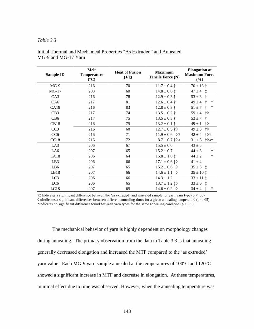
143
Table 3.3
Initial Thermal and Mechanical Properties “As Extruded” and Annealed
MG-9 and MG-17 Yarn
Sample ID
Melt
Temperature
(°C)
Heat of Fusion
(J/g)
Maximum
Tensile Force (N)
Elongation at
Maximum Force
(%)
MG-9 216 70 11.7 ± 0.4 † 70 ± 13 †
MG-17 203 60 14.8 ± 0.6 ‡ 47 ± 4 ‡
CA3 216 78 12.9 ± 0.3 † 53 ± 3 †
CA6 217 81 12.6 ± 0.4 † 49 ± 4 † *
CA18 216 83 12.8 ± 0.3 † 51 ± 7 † *
CB3 217 74 13.5 ± 0.2 † 59 ± 4 †◊
CB6 217 75 13.5 ± 0.3 † 53 ± 7 †
CB18 216 75 13.2 ± 0.1 † 49 ± 1 †◊
CC3 216 68 12.7 ± 0.5 †◊ 49 ± 3 †◊
CC6 216 71 11.9 ± 0.6 ◊¤ 42 ± 4 †◊¤
CC18 216 72 8.7 ± 0.7 †◊¤ 31 ± 6 †◊¤*
LA3 206 67 15.5 ± 0.6 43 ± 5
LA6 207 65 15.2 ± 0.7 44 ± 3 *
LA18 206 64 15.8 ± 1.0 ‡ 44 ± 2 *
LB3 206 66 17.1 ± 0.6 ‡◊ 41 ± 4
LB6 207 65 15.2 ± 0.6 ◊ 35 ± 5 ‡
LB18 207 66 14.6 ± 1.1 ◊ 35 ± 10 ‡
LC3 206 66 14.3 ± 1.2 33 ± 11 ‡
LC6 206 65 13.7 ± 1.2 ‡◊ 33 ± 6 ‡
LC18 207 65 14.6 ± 0.2 ◊ 34 ± 4 ‡ *
†‡ Indicates a significant difference between the „as extruded‟ and annealed sample for each yarn type (p < .05)
◊ ¤Indicates a significant differences between different annealing times for a given annealing temperature (p < .05)
*Indicates no significant difference found between yarn types for the same annealing condition (p < .05)
The mechanical behavior of yarn is highly dependent on morphology changes
during annealing. The primary observation from the data in Table 3.3 is that annealing
generally decreased elongation and increased the MTF compared to the „as extruded‟
yarn value. Each MG-9 yarn sample annealed at the temperatures of 100°C and 120°C
showed a significant increase in MTF and decrease in elongation. At these temperatures,
minimal effect due to time was observed. However, when the annealing temperature was

144
increased to 140ºC the effect of each step increase in time produced a reduction in MTF
and elongation. For the extreme condition of sample CC18, MG-9 yarn produced the
lowest MTF and elongation values observed in the study. The MTF for MG-17 was
greater than that of MG-9 for the „as extruded‟ and for each annealing condition.
However, for MG-17 an increase in MTF due to annealing was less pronounced. For
example, the LA18 and LB3 were the only samples which had a significant increase in
MTF after annealing. Of the two samples, the LB3 sample produced the greatest MTF
value in the study (p < .003) at 17.1 N.
Figure 3.1 presents DMA curves for each „as extruded‟ yarn and a typical
response of each yarn type to annealing. Figures 3.2 and 3.3 isolate the tan δ response to
depict the effect of annealing time and temperature, respectively. A complete set of
DMA results which includes all annealing conditions for both yarn types is tabulated in
Table 3.4.
In Figure 3.1 it can be seen that, for both yarn types, the glass transition region
encompasses a peak for both the tan δ and E‟‟ curves as well as a significant decrease in
E‟. Annealing increased the peak position of the tan δ curve (Tg), increased the breadth
and reduced the height of the tan δ peak, increased the storage modulus onset
temperature, and modified the rubbery plateau (region between Tg and Tm) such that
stiffness was increased. Comparing the two yarn types, MG-17 and MG-9, it can be seen
that MG-9 has a lower Tg, peak of the E‟‟ curve, and E‟ reduction onset temperature. It is
interesting to note that the storage modulus was greater for the MG-9 yarn during the
rubbery plateau.

145
Figure 3.1
The storage modulus (E‟), loss modulus (E‟‟), and tan δ response for the “as extruded”
(top) and annealed (bottom, 120°C for 60 minutes) MG-9 (dashed) and MG-17 (solid)
yarn. Depicted data presented as a comparative typical effect of annealing on the
thermomechanical properties.

146
A direct comparison of the tan δ responses for annealed yarn depicting the effect
of annealing time and temperature is displayed in Figures 3.2 and 3.3, respectively. For
MG-9 yarn, differences in the tan δ curve between annealing times or temperatures was
minimal. However, the height, breadth, and peak position of tan δ for MG-17 yarn was
sensitive to changes in annealing conditions with step increases in temperature showing
the most significant shifts. Most notable was the tan δ peak shift toward a lower
temperature for MG-17 at the temperature of 140°C.
Figure 3.2
The typical tan δ response of annealed MG-9 and MG-17 yarn depicted for the annealing
temperature of 120ºC conditioned for the times of 30 (blue), 60 (green), and 180
(maroon) minutes. “As extruded” (red) data has been included for comparison.

147
Of significant interest is the proximity of the onset or shift in the baseline of the
tan δ curve with reference to physiologic temperature (37°C). The onset of the Tg
transition for MG-9 is significantly lower than that of MG-17. As such, at 37°C the MG-
9 tan δ curve shows changes in the slope of the curve indicating the initiation of
molecular mobility and increased free volume. At 37°C, nearly all of the tan δ curves for
the depicted MG-17 yarn samples have minimal, or no slope, indicating the relaxation
event of Tg has not initiated. Exceptions to this finding for MG-17 yarn include the „as
extruded‟ and samples annealed at 140°C for 30 minutes.
Figure 3.3
The typical tan δ response of annealed MG-9 and MG-17 yarn depicted for the annealing
time of 30 minutes conditioned at the temperatures of 100°C (blue), 120°C (green), and
140°C (maroon). “As extruded” (red) data has been included for comparison.

148
The principal observation from the DMA data presented in Table 3.4 is that in all
cases, initial and annealed, the Tg of MG-17 yarn was greater by 4-6°C than that of MG-9
yarn. In addition to changes in peak position of tan δ, changes to the onset temperature of
tan δ were dramatic following annealing. The annealing conditions of 100°C for 180
minutes and 120°C for 30 and 60 minutes produced the greatest onset temperatures for
both yarn types. But at the same time, MG-17 produced onset values about 16°C greater
than that of MG-9. When the annealing temperature was increased from 120°C to 140°C,
the tan δ onset temperature initiated earlier for both yarn types. The peak height of tan δ
for annealed MG-9 yarn was generally lower than that of MG-17.

149
Table 3.4
Thermomechanical Properties of “As Extruded” and Annealed MG-9 and MG-17 Yarn
Determined by DMA
Sample ID Tg (°C) Tan δ half-
width (°C)
Onset of
Tan δ (°C)
Peak
Height of
Tan δ
Onset of
Storage
Modulus
(°C)
Peak of Loss
Modulus, E’’
(°C)
MG-9 62 27 28 0.309 47 54
MG-17 67 27 34 0.265 49 57
CA3 65 27 29 0.185 51 57
CA6 66 28 28 0.185 50 57
CA18 67 29 35 0.178 50 59
CB3 66 26 37 0.185 49 58
CB6 66 27 37 0.174 46 57
CB18 66 28 34 0.177 49 58
CC3 65 31 29 0.170 51 57
CC6 62 25 33 0.175 45 54
CC18 65 24 33 0.176 47 57
LA3 71 21 49 0.219 56 62
LA6 70 23 46 0.218 56 62
LA18 72 18 53 0.204 60 64
LB3 72 18 53 0.203 59 63
LB6 72 20 53 0.191 58 65
LB18 71 20 50 0.192 56 62
LC3 69 27 40 0.188 51 58
LC6 69 31 38 0.188 54 61
LC18 69 36 30 0.179 51 58
Annealing increased yarn dimensional stability as shown by the data listed in
Table 3.5. Initially, MG-17 shrank approximately twice the amount as MG-9 yarn. For
both yarn types all post-annealed shrinkage measurements were lower than the „as
extruded‟ initial value (p < .04). In spite of the dramatic reductions observed for MG-17,
post-annealed shrinkage measurements for MG-9 yarn remained lower.

150
Table 3.5
Percent Shrinkage and Shrinkage Onset Temperature of “As Extruded”
and Annealed MG-9 and MG-17 Yarn
Sample ID Shrinkage at 80°C
(%)
Shrinkage at 120°C
(%)
Shrinkage Onset
Temperature
(ºC)
MG-9 5.6 ± 0.5 7.1 ± 0.9 43.0 ± 0.9 *
MG-17 10.2 ± 2.2 14.1 ± 1.3 44.1 ± 1.0 *
CA3 2.9 ± 0.6 † 5.0 ± 1.0 † 46.7 ± 1.4 †
CA6 2.2 ± 0.1 4.6 ± 0.3 ‡ 46.4 ± 1.0 ‡
CA18 1.7 ± 0.2 † 3.5 ± 0.3 †‡ 49.9 ± 0.3 †‡
CB3 1.6 ± 0.2 2.3 ± 0.2 52.7 ± 0.3
CB6 1.8 ± 0.4 2.9 ± 0.5 51.3 ± 1.7 *
CB18 1.6 ± 0.2 2.2 ± 0.3 51.9 ± 0.8
CC3 2.0 ± 0.3 2.5 ± 0.3 44.8 ± 1.0 † *
CC6 1.9 ± 0.1 * 2.5 ± 0.3 47.1 ± 1.6 †‡
CC18 1.6 ± 0.2 1.9 ± 0.1 42.2 ± 0.7 †‡
LA3 6.5 ± 0.5 † 12.7 ± 0.5 † 49.0 ± 1.0 †
LA6 5.1 ± 1.1 † 11.6 ± 2.0 51.3 ± 0.9 †
LA18 4.3 ± 0.5 † 11.3 ± 1.3 † 52.4 ± 1.1 †
LB3 3.5 ± 0.3 † 7.8 ± 0.8 † 50.3 ± 1.6
LB6 3.6 ± 0.4 7.7 ± 0.8 ‡ 50.6 ± 1.0 *
LB18 2.6 ± 0.4 † 5.9 ± 0.8 †‡ 49.4 ± 0.3
LC3 4.0 ± 0.5 † 7.7 ± 1.2 † 44.8 ± 0.6 † *
LC6 2.1 ± 0.1 †* 4.0 ± 0.4 † 48.8 ± 1.4 †‡
LC18 2.8 ± 0.4 † 4.4 ± 0.7 † 46.3 ± 0.7 ‡
†‡ Indicates a significant difference within each yarn type between different annealing times for the indicated annealing
temperature (p < .05)
*Indicates no significant difference found between yarn types for the same treatment conditions (p < .05)
At the annealing temperature of 100°C, increased annealing time significantly
reduced yarn shrinkage for both yarn types. However, varying the annealing time did not
produce any differences in shrinkage values for MG-9 at the annealing temperatures of
120°C and 140°C. On the contrary, the shrinkage of MG-17 yarn continued to be
reduced as annealing time increased at the annealing temperatures of 120°C and 140°C.

151
On the whole, MG-17 yarn required greater temperatures and times to influence
shrinkage measurements, whereas MG-9 yarn was mostly unresponsive to annealing
conditions beyond a temperature of 100°C for 60 minutes.
All temperature onset measurements for annealed samples were greater than the
„as extruded‟ values (p < .01), with the exception of samples CC18 and LC3. In these
two cases, no difference was observed. In addition, it is interesting to note that for the
onset temperature there was no difference between the MG-9 and MG-17 „as extruded‟
yarn samples. For MG-9 yarn, annealing at 100°C increased the onset temperature with a
continuation of this trend as annealing time increased. Further improvements were
obtained at the annealing temperature of 120°C; however, at this temperature no
difference was determined due to time. MG-17 showed a similar trend, but rather than an
increase, a slight decrease was observed for each step change in time at the annealing
temperature of 120°C. Annealing at 140°C had a negative effect on the shrinkage onset
temperature for MG-9 and MG-17. All in all, similar initial and maximum shrinkage
onset temperatures were observed between the two yarn types of approximately 44°C to
52°C, respectively.

152
Figure 3.4
A typical Arrhenius plot demonstrating the relationship between logarithmic frequency
and reciprocal peak temperature for the Tg transition. Depicted data is for the annealing
condition of 120ºC. Reported linear slope and correlation coefficient data is organized in
the same configuration as presented in the legend.
Figure 3.4 depicts the relationship used to determine the activation energy
associated with each annealing condition determined by the associated slope (Ea) (data
for the other annealing temperatures not shown). In addition, the correlation coefficient
(R2) has been reported to assess linear fit. A strong linear response was found (R
2 >

153
0.970) which validates the Arrhenius relationship. Figure 3.5 depicts the resulting Ea
data as a function of annealing temperature for different annealing times.
Figure 3.5
The apparent activation energies of the Tg transition calculated from the slope of the
Arrhenius plot. The activation energies for the “as-extruded” samples were 419 kJ/mol
and 466 kJ/mol for the MG-9 and MG-17, respectively.
Several interesting observations can be made from the data in Figure 3.6. First,
minimal differences in Ea were observed for data within each yarn type at the three

154
annealing temperatures. Second, a maximum occurred for both yarn types at the
temperature of 120°, regardless of annealing time. Lastly, a clear separation existed
between the two yarn types with the Ea of the Tg transition for MG-17 substantially
greater than that of MG-9.
† Indicates a significant differences between 21 day in vitro samples (p < .05)
Figure 3.6
The temporal in vitro conditioned maximum tensile force for MG-9 and MG-17 samples
annealed at 100ºC for 30, 60, and 180 minutes.

155
From inspection of the data in Figures 3.6, 3.7, and 3.8, clearly the annealing
process increased the temporal in vitro conditioned MTF for both yarn types. The only
exception to this observation is the MG-9 sample annealed at 140°C for 180 minutes
which produced lower MTF values than that of the „as extruded‟ sample. In all cases,
MG-9 and MG-17 produced a reduction in strength that was immediate, continuous, and
almost linear. However, the rate of that change or slope of the resultant profile was
variable. Of specific importance is that MG-17 showed greater MTF values for all
annealing temperatures and annealing times through 14 days. MG-9 showed a steeper
slope that resulted in low MTF values by 14 days and no measurable results by 21 days.
In contrast, all annealed MG-17 samples produced measurable MTF values at 21 days.

156
Figure 3.7
The temporal in vitro conditioned maximum tensile force for MG-9 and MG-17 samples
annealed at 120ºC for 30, 60, and 180 minutes. (No significant differences found between
MG-17 samples at 21 days of in vitro conditioning (p < .05))
At the in vitro time point of 21 days, annealing at 100°C for 180 minutes was not
significantly different than each of the samples annealed at 120°C (p > .06) Samples
annealed at 140°C were significantly lower than any of those annealed at 120°C (p < .01).
In brief, the longest time period of 180 minutes for the lowest annealing temperature, as
well as, all of the annealing times at 120°C produced similar, and the highest temporal

157
MTF values for MG-17 yarn. The temporal in vitro conditioned MTF values for MG-9
were significantly lower and marginally met the 14 day strength retention objective.
Figure 3.8
The temporal in vitro conditioned maximum tensile force for MG-9 and MG-17 samples
annealed at 140ºC for 30, 60, and 180 minutes. (No significant differences found between
MG-17 samples at 21 days of in vitro conditioning (p < .05))

158
Discussion
Three distinct variables were investigated to develop a high-glycolide copolymer
for use in the construction of a bicomponent mesh. Specifically, comonomer
composition, annealing time, and annealing temperature were investigated to determine
their effect on the initial maximum breaking force, temporal in vitro conditioned
maximum breaking force profile, and yarn stabilization against dimension changes. In
addition to the direct measurement of these study objectives, several analytical techniques
were employed to better understand morphological differences including thermal
properties by DSC and viscoelastic properties by DMA. Significant results related to
each copolymer and for each investigated annealing time and temperature will be
discussed.
As polymerized, MG-17 revealed a clear reduction in Tm and crystallinity
compared to MG-9. The peak temperature of the melting event is driven by crystallite
perfection and thickness. Chu described that when a PLL comonomer is dispersed in PG,
the sheet crystalline structure (also described as planar zig-zag) is disturbed because the
methyl group affects chain packing.27
The steric effect from the pendant methyl group of
PLL protruding outward along the main chain of MG-17 likely interrupts the regular,
repeat structure between adjacent chains, resulting in a less perfect crystalline structure.
For comparison, the Tm for a homopolymer of PG is about 225°C. A commonly used and
widely investigated copolymer for suture and meshes is polyglactin 910, a random
copolymer of 90/10 poly(glycolide-co-lactide) which, compared to PG, displays (1) a
lower Tm of about 205°C and less crystallinity and (2) a slower crystallization rate.28
159
These reported findings are similar to the reduction observed for MG-17. Following
melt-extrusion, greater differences in Tm and degree of crystallinity were observed
between MG-9 and MG-17.
During processing, each polymer was melted, extruded, and in-line oriented into
fibers to produce a 10-filament yarn. As a result, crystallinity is developed which is
detectable by DSC. In effect, during the extrusion process molten polymer is cooled
rapidly, or quenched, which does not allow sufficient time for complete crystallization
leaving a substantial amorphous fraction that upon reheating will partially crystallize. An
inherent characteristic of absorbable polyesters is that their crystallization kinetics are
relatively slow. As such, the effect of different molecular structures becomes magnified
as a result of the rapid quenching during the melt-extrusion process. This difference was
evident between MG-17 and MG-9. MG-17 showed a greater difference in Tm between
the synthesized copolymer and “as extruded” yarn compared to that of MG-9.
Furthermore, during annealing appreciable increases were observed for MG-17. As such,
it is likely that the added kinetic energy facilitated a reorganization of the crystallite
structure for MG-17 that was initially hindered by the dispersed lactide moiety. Some
disturbance was also realized as a result of using PCL as a comonomer in MG-9.
However, the reduction in Tm and degree of crystallinity was less pronounced due to the
lack of a bulky side group in the monomers. It is interesting to note that for MG-9 yarn,
minimal differences in Tm were observed following annealing. This was likely the result
of faster crystallization kinetics which initially produced greater crystallite perfection that

160
did not significantly change during annealing. Instead only an increase in the degree of
crystallinity was observed.
The mechanical tensile properties of MTF and elongation have significant
influence on the maximum burst force of meshes. For the investigated yarns, one might
have hypothesized that MG-17 would elongate more than MG-9 due to the greater weight
percent of the low Tg and low modulus pTMC macroinitiator in the MG-17. Results
indicated the contrary, however; mechanical tensile testing showed that MG-9 yarn
produced significantly greater elongation. The interlocking effect of the added lactide
monomer units between adjacent chains dominated the extensional behavior and negated
any effect from the greater molecular weight of the pTMC segment. Likewise, steric
hindrance and molecular interlocking prevented rotational and translational mobility
between adjacent chains in the amorphous domain, resulting in greater chain
entanglement and thus greater MTF for MG-17. A similar response was observed when
tercopolymer of PCL, TMC, and PLL with different molar ratios were synthesized.29
The
authors noted that as the content of PLL increased, chain slippage decreased, which
increased the tensile strength and decreased elongation.
The temperature position, height, onset temperature, and temperature range of tan
δ provide quantitative measures which are related to the degree of crystallinity and
morphology of semicrystalline polymers. The amorphous and crystalline domains of
fibers are intimately connected which has an effect on the Tg relaxation. The temperature
of the Tg relaxation is a measure of chain rigidity and resistance to segmental molecular
mobility. As such, segmental movement must overcome chain friction and steric barriers.
161
This interaction is detectable in the breadth, peak, and onset of the Tg transition as
segmental motion in the amorphous region is constrained or unrestrained due to different
annealing conditions. Furthermore, the onset temperature for the reduction in storage
modulus is also an indicator of how well the amorphous region is constrained by
annealing to long-range segmental motion. It should be noted that the values determined
for Tg using DMA are higher than those determined using the more commonly used DSC
method. Other authors have reported the same observation.19
This difference lies in the
fact that each technique measures a different property. DSC measures differences in
specific heat while DMA measures thermally induced molecular mobility.
The Tg transition represents a major physical change to the polymer as it goes
from a „glassy‟ structure with limited molecular mobility to the „rubbery‟ state with
increased free volume and chain mobility within the amorphous domain. A significant
finding, which has substantial influence on degradation rate, was that the Tg of MG-17
yarn (69-72°C) was greater by 4-6°C than that of MG-9 (65-66°C). Again, adding PLL
increased the barrier to molecular rotation and translation leading to a higher Tg. Values
of Tg determined using DMA for a homopolymer of PLG and polyglactin 910 yarn in
suture form have been reported as 72°C and 74°C, respectively.30
Similar to results of
the present study, the addition of PLL as a comonomer to PG increased the temperature
of the Tg relaxation event. Moreover, in a study by Penning and coworkers,31
PLL was
polymerized with a 0.10 and 0.05 molar fraction of PCL or D-lactide, respectively. Of
interest was the response of Tg, Tm, and heat of fusion to the addition of each comonomer
unit. In the case of PCL, a reduction in all three thermal properties was observed.

162
However, the addition of D-lactide maintained the value of Tg but depressed, even more
dramatically than PCL, the Tm and heat of fusion values. Although the major component
was PLL and not PG as used in the current study, the response was similar to that of MG-
17 and MG-9. Steric effects from lactide heavily influenced crystallite formation and
perfection, which significantly lowered the Tm and heat of fusion values. PCL had the
same effect but to a lesser degree. The dramatic reduction in Tg when PCL was
introduced was explained as being the result of the extremely low Tg of PCL (Tg = -60°C)
which shifted the Tg a proportional amount to its molar content. Again, this was similar
to the Tg response of MG-9. Since the Tg of D-lactide is the same as L-lactide no
difference was observed. Therefore, for the monomers used in the present study, the
reduction in MG-9 was likely the result of the low Tg of PCL, while the increase in MG-
17 was from the greater Tg of PLL.
Differences in the amount of soft segment were most noticeable in the DMA
storage modulus curves. The finding that the storage modulus was greater for the MG-9
yarn within the rubbery plateau is related to the amount of soft segment within each
copolymer and differences in the degree of crystallinity. Below Tg the stiffness of the
chain backbone is highly influential on the stiffness of the polymer. As such, the greater
proportion of the soft polymeric initiator in MG-17 is a likely cause for the lower E‟
response below Tg. In addition, the height of the rubbery plateau is related to a polymers
degrees of crystallinity. Crystallites resist chain slippage which results in a greater elastic
response. Compared to MG-9, MG-17 was less crystalline which was concluded from
DSC measurements.

163
There is a well documented link between degradation rate and crystallinity.3,32
Higher degrees of crystallinity prolong the strength retention profile by inhibiting the
access of water to molecular chains which are protected within tightly packed crystallites.
However, crystallinity alone does not dictate degradation rate. Rather it is the
accessibility of water to the amorphous domain which is also influenced by molecular
orientation, Tg, and the hydrophobicity of the constituent monomers.33
This study
illustrates this point; MG-9 was more crystalline yet it showed an increased rate of
degradation. The explanation for this finding can be found in differences in Tg.
Of particular interest to this study is the in vitro conditioned retention of
mechanical strength as it has the greatest impact on the function of the device. The
greater Tg of MG-17 influenced the temporal in vitro conditioned strength retention
profile. The affect of Tg on degradation rate is evidenced in the DMA tan δ curve for
each yarn type and at each annealing condition. With overall lower Tg values for MG-9,
the tan δ curve begins to increase sooner than that of MG-17. From the tan δ onset
temperature it is clear that MG-9 began to show evidence of the initiation of the Tg
relaxation event at or below physiologic temperature. The increase in tan δ marks a
physical increase in free volume for the copolymer, induced by molecular movement. A
consequence of this increased free volume, it would be expected that larger gaps between
chains would increase the diffusion of water. This is a significant finding since porosity
is a major factor which affects degradation rate. For the majority of the investigated
annealing conditions, MG-17 does not show any increase in tan δ until 10°C, or more,
above physiologic temperature. This finding correlates well with the in vitro conditioned

164
MTF data which indicated that MG-17 in all cases has better in vitro conditioned strength
retention.
Changes to the size and shape of a fibrous medical device due to elevated
temperature during sterilization or shipment is often detrimental to its intended function.
In addition to undesirable dimensional changes, a relaxed yarn will have modified initial
and temporal in vivo mechanical properties. These changes result from the thermal
relaxation of orientation within the amorphous region which is triggered by entropic
molecular changes to acquire a lower energy conformation. In this study, the annealing
process was found to substantially decrease the amount of shrinkage and increase the
shrinkage onset temperature. Although the annealing process imparts resistance to
deformation from the relaxation of some chains and the crystallization of others, for
fibers this process is never absolute. MG-17 exhibited about two times more free
shrinkage than MG-9. It is reasonable to expect that steric effects induce stressed chain
configurations, which were frozen in as the yarn transitioned into the glassy state during
fiber orientation. Consequently, MG-17 experienced substantially more thermally
induced free shrinkage as the stressed chains were allowed to relax into lower energy
conformations. In the case of MG-9, the PCL comonomer unit would have imparted
increased chain flexibility that facilitated chains to assume lower stress levels.
Furthermore, the greater crystallinity of MG-9 would have better constrained the
microstructure against relaxation. Regardless, for annealed samples equal to or greater
than 120°C, the absolute amount of shrinkage at 80°C is low. For comparison, using a
similar technique, Fu and coworkers19
determined that polyglactin 910 sutures processed

165
and annealed at different conditions produced shrinkage values from 3.3 to 5.1% at 80°C.
These values are comparable to those obtained for MG-17 and slightly greater than MG-
9. The temperature at which the shrinkage initiates, i.e. the shrinkage onset temperature,
is equally important to the dimensional stability of yarn as is the absolute amount of
shrinkage. The amount of shrinkage at the onset of shrinkage temperature would be
expected to be essentially zero at typical end-use (37°C) and sterilization temperatures (<
42°C); both yarn types met this criterion when annealing was conducted at temperatures
greater than 120°C.
Since the rearrangement of polymer chains into crystallites is time dependent, it
was important to determine the effect of different annealing times on each yarn type.
Longer annealing times allow more chains to diffuse into suitable orientations for
crystalline arrangement; thus, the perfection, size, and degree of crystallinity increase
with increased annealing time.34
In this study minimal differences in degrees of
crystallinity were observed between the annealing times of 30, 60, and 180 minutes,
indicating that the percent of crystallite formation within both copolymers was achieved
prior to the lowest time point of 30 minutes. This result has been observed for the slower
crystallizing PLL homopolymer. Molded articles of PLL have been shown to reach
equilibrium with regard to percent crystallinity by 30 minutes for the same investigated
annealing temperatures.35
However, although differences in amount of crystallinity were
not observed between each annealing time, changes in morphology were apparent.
At the studied annealing temperatures and given adequate time, polymer chains
have sufficient mobility that, below a critical size, small crystallites melt and create larger
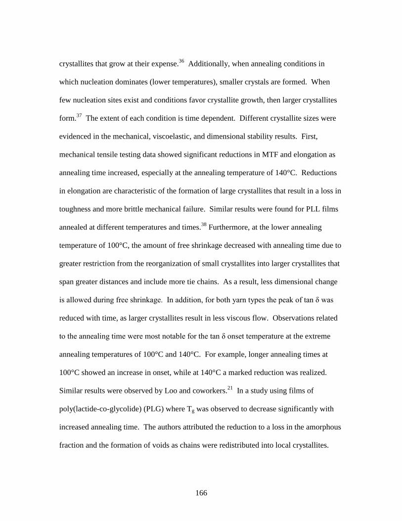
166
crystallites that grow at their expense.36
Additionally, when annealing conditions in
which nucleation dominates (lower temperatures), smaller crystals are formed. When
few nucleation sites exist and conditions favor crystallite growth, then larger crystallites
form.37
The extent of each condition is time dependent. Different crystallite sizes were
evidenced in the mechanical, viscoelastic, and dimensional stability results. First,
mechanical tensile testing data showed significant reductions in MTF and elongation as
annealing time increased, especially at the annealing temperature of 140°C. Reductions
in elongation are characteristic of the formation of large crystallites that result in a loss in
toughness and more brittle mechanical failure. Similar results were found for PLL films
annealed at different temperatures and times.38
Furthermore, at the lower annealing
temperature of 100°C, the amount of free shrinkage decreased with annealing time due to
greater restriction from the reorganization of small crystallites into larger crystallites that
span greater distances and include more tie chains. As a result, less dimensional change
is allowed during free shrinkage. In addition, for both yarn types the peak of tan δ was
reduced with time, as larger crystallites result in less viscous flow. Observations related
to the annealing time were most notable for the tan δ onset temperature at the extreme
annealing temperatures of 100°C and 140°C. For example, longer annealing times at
100°C showed an increase in onset, while at 140°C a marked reduction was realized.
Similar results were observed by Loo and coworkers.21
In a study using films of
poly(lactide-co-glycolide) (PLG) where Tg was observed to decrease significantly with
increased annealing time. The authors attributed the reduction to a loss in the amorphous
fraction and the formation of voids as chains were redistributed into local crystallites.

167
Several other authors have noted that for poly(ethylene terephthalate), increased
crystallinity increases Tg, to a point, and then a further increase to crystallinity results in a
reduction in Tg.39-41
In this study, shifts in Tg were apparent but less dramatic, likely due
to the highly oriented and crystalline nature of the yarn. Rather, more dramatic changes
were noted in the onset of the tan δ event with reductions as annealing temperature and
time increased. The effect of this phenomenon was also witnessed in the temporal in
vitro conditioned strength retention.
Differences in annealing time had a clear impact on the temporal in vitro
conditioned MTF profile. For MG-17 yarn, at the temperature of 100°C the strength
profile benefited significantly when the time point was increased from 60 to 180 minutes.
Reductions in the in vitro conditioned strength profile for both yarn types were
consistently lower when the annealing temperature was increased from 120°C to 140°C.
These findings were similar to those found for the previously mentioned PLG films.21
In
that study, the degradation rate was reported to decrease for annealing times less than 30
minutes and increase when annealing time was greater than 30 minutes. As before, the
authors attributed the initial decrease in degradation rate to crystallites retarding water
penetration, followed by a loss in the amorphous fraction which created voids that
allowed greater water uptake and faster hydrolysis. Another explanation for the
increased degradation rate and loss of mechanical strength due to increased crystallinity
of absorbable polymers has been suggested by Tsuji.42,43
Studies showed that for PLL
films a higher initial crystallinity was found to result in enhanced hydrolysis. The
authors suggested that an increased density of hydrophilic terminal carboxyl and

168
hydroxyl groups, which are excluded from crystalline domains, causes loose chain
packing and an increase in the diffusion rate of water into amorphous domains. The
increased degradation rate associated with advanced crystallite formation determined in
these studies parallel the results of both yarn types in this study, specifically the
annealing conditions which produced enhanced crystallization. Namely, annealing at
140°C produced diminishing in vitro conditioned strength retention with each step
increase in time.
As demonstrated, the three annealing temperatures were all influential on the
properties of both yarn types. However, the temperature of 120°C increased the
mechanical properties, Tg, onset temperature for tan δ, onset temperature of E‟, peak of
the E‟‟ curve, and produced the greatest temporal in vitro strength retention for both MG-
9 and MG-17 yarn. This data was further supported by the calculated Ea for each yarn
type and each annealing condition. The activation energy provides a quantitative
measurement of the energy required to transition through the thermomechanical
relaxation event of Tg. As such, it provides information about how well the amorphous
region was constrained. In other words, it is effectively the energy barrier that the
material has to overcome in order to generate segmental molecular motion on a long-
range scale. The obtained Ea values were clearly greater for MG-17 and produced a
maximum at 120°C which corresponded with the copolymer and annealing temperature
that resulted in the greatest initial strength, highest tan δ onset temperature, and greatest
in vitro conditioned strength retention. On the other hand, a reduction in Ea was observed
at the annealing temperature of 140°C. Overall, annealing at 140°C resulted in a

169
reduction in properties. This was most notable in the reduced mechanical properties,
lower Tg values, and faster degradation rate. When annealing was conducted at 100°C
morphology development required the longer time point of 180 minutes to achieve
marked increases in the onset of tan δ, shrinkage, and a greater strength retention in vitro
profile.
For copolymers, two or more inherently incompatible polymer sequences are
forced to co-exist in a single phase. The coupling of their properties results in a single Tg
relaxation which is between each individual segments homopolymer. The properties of
the investigated copolymers in this study were largely influenced by the temperature of
the Tg relaxation. Steric effects from the addition of the PLL in MG-17 increased Tg, and
more importantly, the onset temperature of the tan δ transition. It is difficult to predict
the in vivo performance of an absorbable yarn based on only a single characteristics as
there are many interactions; however, in this study the most influential factor on the
initial and temporal in vitro conditioned strength profile was the replacement of PCL with
PLL for MG-17.
Conclusion
A high-glycolide yarn was developed for use in a bicomponent mesh for hernia
repair whereby its function requires strength retention during the inflammatory and
proliferation period of healing with subsequent gradual transfer of the load to remodeling
tissue. Chemical modification resulted in two triaxial, segmented high-glycolide
copolymers for evaluation, namely MG-9 and MG-17. Experimental results indicated
that the addition of L-lactide as a comonomer in MG-17, compared to ε-caprolactone for

170
MG-9, increased Tg, the onset of the tan δ transition, the Ea of the Tg transition, the
maximum tensile force, and decreased the tensile elongation. A further aim of this work
was to determine the isothermal annealing time and temperature which optimized the
temporal in vitro conditioned strength profile. In summary, it can be concluded that MG-
17 annealed at a temperature of 120°C for 30 minutes met the desired functional
requirements and provided the greatest initial maximum tensile force, longest temporal in
vitro conditioned strength retention, and yarn stabilization against dimensional changes
induced by unrestrained thermal relaxation.

171
References
1. Nair L, Laurencin C. Biodegradable polymers as biomaterials. Progress in
Polymer Science 2007;32:762-798.
2. Engelberg I, Kohn J. Physico-mechanical properties of degradable polymers used
in medical applications: a comparative study. Biomaterials 1991;12(3):292-304.
3. Chu CC. Hydrolytic degradation of polyglycolic acid: tensile strength and
crystallinity study. Journal of Applied Polymer Science 1981;26:1727-1734.
4. Craig P, Williams J, David K. A biological comparison of polyglactin 910 and
polyglycolic acid synthetic absorbable sutures. Surg Gynecol Obstet 1975;141:1-
10.
5. Barrows T. Degradable implant materials: a review of synthetic absorbable
polymers and their applications. Clin Mat 1986;1:233-257.
6. Bergsma JE, Rozema FR, Bos RR, Boering G, de Bruijn WC, Pennings AJ.
Biocompatibility study of as-polymerized poly(L-lactide) in rats using a cage
implant system. J Biomed Mater Res 1995;29(2):173-9.
7. Lee S, Kim K, Kang SW, Kim C. Microstructural analysis and structure-property
relationship of poly(glycolide-co-1,3-trimethylene carbonate). Polymer
2005;46:7953-7960.
8. Metz SA, Chegini N, Masterson BJ. In vivo and in vitro degradation of
monofilament absorbable sutures, PDS and Maxon. Biomaterials 1990;11(1):41-
5.
9. Middleton JC, Tipton AJ. Synthetic biodegradable polymers as orthopedic
devices. Biomaterials 2000;21(23):2335-46.
10. Gopferich A. Mechanisms of polymer degradation and erosion. Biomaterials
1996;17(2):103-14.
11. Wang Y, Ribelles J, Sanchez M, Mano J. Morphological contributions to glass
transition in poly(L-lactic acid). Macromolecules 2005;38:4712-18.
12. Pego A, Feijen G. Enhanced mechanical properties of 1,3-trimethylene carbonate
polymers and networks. Polymer 2003;44:6495-6504.

172
13. Jie C, Zhu K, Shilin Y. Preparation, characterization and biodegradation
characteristics of poly(1,3-trimethylene carbonate-co-glycolide). Polym Int
1996;41:369-375.
14. Noorsal K, Mantle M, Gladden L, Cameron R. Degradation and drug-release
studies of a poly(glycolide-co-trimethylene carbonate) copolymer (Maxon). J
Appl Polym Sci 2005;95:475-786.
15. Bezwada RS, Jamiolkowski DD, Lee IY, Agarwal V, Persivale J, Trenka-Benthin
S, Erneta M, Suryadevara J, Yang A, Liu S. Monocryl suture, a new ultra-pliable
absorbable monofilament suture. Biomaterials 1995;16(15):1141-8.
16. Deng M, Zhou J, Chen G, Burkley D, Xu Y, Jamiolkowski D, Barbolt T. Effect of
load and temperature on in vitro degradation of poly(glycolide-co-L-lactide)
multifilament braids. Biomaterials 2005;26(20):4327-36.
17. Montes de Oca H, Ward IM. Structure and mechanical properties of PGA crystals
and fibres. Polymer 2006;47:7070-77.
18. Fredericks R, Melveger A, Dolegiewitz L. Morphological and structural changes
in a copolymer of glycolide and lactide occurring as a result of hydrolysis. J Poly
Sci (Poly Phys Ed) 1984;22:57-66.
19. Fu B, Hsiao, B., Chen, G., Zhou, J., Koyfman, I., Jamiolkowski, D., Dormier, E.
Structure and property studies of bioabsorbable poly(glycolide-co-lactide) fiber
during processing and in vitro degradation. Polymer 2002;43:5527-5534.
20. Cowie J. Polymers: chemistry and physics of modern materials. New York:
Chapman and Hall; 1991.
21. Loo SC, Ooi CP, Wee SH, Boey YC. Effect of isothermal annealing on the
hydrolytic degradation rate of poly(lactide-co-glycolide) (PLGA). Biomaterials
2005;26(16):2827-33.
22. Wetton R. Dynamic mechanical thermal analysis of polymers and related systems.
In: Dawkins J, editor. Development in polymer characterization. Barking:
Elsevier; 1986.
23. Wetton R. Dynamic mechanical method in the characterization of solid polymers.
Polymer Testing 1984;4:117-129.
24. Chu CC, Browning A. The study of thermal and gross morphologic properties of
polyglycolic acid upon annealing and degradation treatments. J Biomed Mater
Res 1988;22(8):699-712.

173
25. Browning A, Chu CC. The effect of annealing treatments on the tensile properties
and hydrolytic degradative properties of polyglycolic acid sutures. J Biomed
Mater Res 1986;20(5):613-32.
26. Cohn D, Younes H, Marom G. Amorphous and crystalline morphologies in
glycolic acid and lactic acid polymers. Polymer 1987;28(12):2018-22.
27. Chu CC. Classification and general characteristics of suture materials. In: Chu
CC, editor. Wound Closure Biomaterials and Devices: CRC Press; 1996. p 39-64.
28. Shalaby SW, Johnson RA. Synthetic absorbable polyesters. In: Shalaby SW,
editor. Biomedical Polymers, Designed-to-Degrade. Cincinnati, OH:
Hanser/Gardner Publications; 1994. p 8-10.
29. Jia Y, Shen X, Gu X, Dong J, Mu C, Zhang Y. Synthesis and characterization of
tercopolymers derived from e-caprolactone, trimethylene carbonate, and lactide.
Polym. Adv. Technol 2008;19:159-166.
30. Von Fraunhofer J, Chu CC. Mechanical Properties. In: Chu CC, editor. Wound
Closure Biomaterials and Devices: CRC Press; 1997. p 118-19.
31. Penning JP, Dijkstra H, Pennings AJ. Preparation and properties of absorbable
fibres from L-lactide copolymers. Polymer 1993;34(5):942-951.
32. Williams DF. Biodegradation of surgical polymers. J Mater Sci 1982;17(5):1233-
46.
33. Reed AM, Gilding DK. Biodegradable polymers for use in surgery -
poly(glycolic)/poly(lactic acid) homo and copolymers: 2. In vitro degradation.
Polymer 1981;22:494-498.
34. Zhoa N, Wang L, Huang D, Zhang T, Zhang L, Xiong C. Effect of isothermal
annealing on degree of crystallinity and mechanical properties of poly(l-lactide-
co-glycolide). Cryst Res Technol 2010;45(3):275-280.
35. Migliaresi C, Cohn D, De Lollis A, Fambri L. Dynamic mechanical and
calorimetric analysis of compression-molded PLLA of different molecular
weights: Effect of thermal treatment. J Appl Polym Sci 1991;43:83-95.
36. Hurrell S, Cameron RE. The effect of initial polymer morphology on the
degradation and drug release from polyglycolide. Biomaterials 2002;23(11):2401-
9.

174
37. Andjelic S, Fitz B, Jamiolkowski D. Advances in morphological development to
tailor the performance of absorbable medical devices. In: Shalaby SW, Burg K,
editors. Absorbable and biodegradable polymers. Boca Raton: CRC Press; 2004.
38. Tsuji H, Ikada Y. Properties and morphologies of poly(L-lactide): 1. Annealing
condition effects on properties and morphologies of poly(L-lactide). Polymer
1995;36(14):2709-2716.
39. Illers K, Breuer H. Molecular motions in polyethylene terephthalate. J Colloid Sci
1963;18(1):1-31.
40. Dumbleton J, Murayama T. Temperature dependence of the dynamic mechanical
behavior of poly(ethylene terephthalate). Colloid Polym Sci 1967;220(1):41-48.
41. Dumbleton J, Murayama T. On the dynamic mechanical behavior of drawn
poly(ethylene terephthalate) fibers. Colloid Polym Sci 1968;228(1-2):54-58.
42. Tsuji H, Mizuno A, Ikada Y. Properties and morphology of poly(L-lactide). III.
Effect of initial crystallinity on long-term in vitro hydrolysis of high molecular
weight poly(L-lactide) film in phoshate-buffered solution. J Appl Polym Sci
2000;77(7):1452-1464.
43. Saha S, Tsuji H. Effects of rapid crystallization on hydrolytic degradation and
mechanical properties of poly(L-lactide-co-E-caprolactone). React Funct Polym
2006;66:1362-1372.

175
CHAPTER FOUR
AN INVESTIGATION OF THE TISSUE RESPONSE AND INTEGRATION
OF AN ABSORBABLE BICOMPONENT CONSTRUCT
IN A RAT MODEL
Introduction
When implanted in living tissues, mesh materials elicit a cellular response which
triggers a tissue reaction that results in the encapsulation of the implant. The
characteristics of the tissue encapsulation are variable and largely dependent on the mesh
design variables of yarn chemistry, yarn form (monofilament or multifilament), yarn size,
and the physical configuration or knit construction. Previously, an absorbable
bicomponent mesh (ABM) comprised of a fast-degrading and slow-degrading yarn was
shown to modulate mesh temporal physical and biomechanical properties for application
in hernia repair (Chapters 2 and 5). As such, the ABM goes through a transition phase
whereby the structural stiffness of the mesh changes from low extensibility to high
extensibility given the same force. This transition is timed to take place between the
inflammation/proliferation phase and the maturation/remodeling phase of the wound
healing process. During the former, the ABM mesh shields the neotissue from
biomechanical stimulation resulting in an integration process primarily influenced by
yarn chemistry, yarn form, and knit construction. In this investigation, a simulated ABM
knit construct was evaluated to determine the cellular and tissue integration response
during the transition phase using a rat model.
Mesh hernia repair efficacy is dependent upon strengthening weak native
abdominal wall tissue by a strong mesh/tissue complex. A significant factor in achieving

176
this objective is the integration of the mesh at the host tissue interface. The acute foreign
body cellular response to the mesh is initially responsible for the mesh-tissue integration
process. For the proposed ABM, the temporal transition period associated with the
substantial degradation of the fast-degrading yarn is a critical timeframe. The
development and optimization of a fast-degrading yarn was shown (Chapter 3) to retain
strength for greater than 18 days. As a result, the ABM possesses a transition period
between 18 and 28 days (Chapter 5). Efficacy of the ABM is dependent on its integration
with the host tissue before the mesh transitions to a state of high extensibility. Significant
integration of the extracellular matrix (ECM) into polypropylene (PP) and
polyethyleneterephthalate (PET) meshes has been observed in animal studies, reducing
abdominal wall compliance 2-3 weeks post implantation.1 This temporal change in the
bending stiffness of the abdominal wall of rats correlated with the histological finding of
activated fibroblasts and the accumulation of collagen. In the same study, grades of
collagen content within the PET mesh steadily increased from 3 days to a maximum at 21
days, with no subsequent change up to 90 days. High-glycolide coated meshes are
associated with vigorous collagen deposition.2,3
Partially-absorbable (PA) meshes which
incorporate a fast-degrading absorbable yarn into a light-weight (LW) PP mesh have been
shown to induce greater cellular activity and fibrosis within the first 28 days post-implant
compared to the LW PP mesh alone.4 Furthermore, the introduction of high-glycolide
filaments into a PA mesh increases the quantity of collagen at 21 days compared to PP
and PET meshes.5 Overall, the use of a fast-degrading absorbable polymer results in an

177
intense cellular reaction followed by greater collagen deposition compared with non-
absorbable yarns.
The tissue response to a new mesh design is often first evaluated in animal
models. In vivo evaluations for absorption and tissue response using the gluteal muscle
of rats as an implantation site has been reported frequently for sutures6,7
and tissue
adhesive analyses.8 This animal model provides two implantation sites to facilitate
paired experimental designs, allowing within animal variability to be minimized when
comparing the effect of two different implant types. As a result, the rat gluteal muscle
model provides a simple method to compare the tissue reaction of different mesh
materials. To evaluate the integration of a mesh into the surrounding tissue it is
important to quantify the extent of encapsulation. To quantitatively characterize changes
in the foreign body response with time, a measure of the inner ring of granuloma (i.e. the
zone of high cellular activity) and the outer ring (i.e. the fibrotic capsule) has been
suggested by several authors.4,7,9
To determine the total amount of collagen deposition
surrounding an implant, Junge and coworkers used a quantitative method based on the
selective binding of histological stains to collagen and noncollagenous protein.5,10
Evaluated with histological qualitative observations, quantitative measurements of
cellular activity and tissue integration provide a mechanism to evaluate device
performance in vivo.
In this investigation, a simulated ABM knit construct was implanted in vivo and
evaluated at 3 and 6 weeks. As a result, the biological reaction to the simulated ABM
construct during the early stability phase was closely simulated. These evaluation time

178
points bracket the transition phase of the proposed ABM to evaluate (1) the extent of
foreign body response measured as the thickness of the granuloma or zone of high
inflammatory cell density, (2) the degree of collagen encapsulation measured as capsule
thickness, and (3) the amount of deposited collagen measured as the collagen/total
protein ratio. Additionally, qualitative histological observations coupled with the
quantitative results provided insight into the anticipated device efficacy. For comparison,
a similar construct comprised of PET yarn served as a clinically-relevant control.
Materials and Methods
Materials
The polymer synthesis and production of yarn for the investigated polymers of
MG-17 (Chapter 3) and SMC-7 (Chapter 2) were described previously. In summary,
MG-17 is a triaxial, segmented, high-glycolide copolymer that is melt-extruded into a 10-
filament yarn. SMC-7 is a linear, segmented, high-lactide copolymer that is melt-xtruded
into a 43-filament yarn. The denier (g/9000m) of the MG-17 and SMC-7 yarn was 150
and 86, respectively. Additionally, a non-absorbable yarn of polyethylene terephthalate
(PET) was procured for use as a control (Unifi, Dacron, 115 denier, 56-filament).
Implant Construction
Using MG-17 and SMC-7 yarns, a warp knitted absorbable bicomponent
construct (ABC) was knit using an 18-gauge raschel knitting machine (American LIBA,
RACOP TR-6). To produce the ABC, a single end of MG-17 was plied with two ends of

179
SMC-7 yarn (S1) prior to knitting and wound onto a spool. Additionally, a three-ply of
SMC-7 yarn (S2) was wound onto a spool in the same manner. Prepared spools of yarn,
S1 and S2, were fed through a tensioning device and then directly into guidebars (GB)
one and two, respectively. Knitting was completed by threading S1 and S2 yarn through
a single guide of each GB such that the construct was produced by knitting around only a
single needle within the needle bar. Using the same knitting process, PET yarn was plied
to closely match the denier of the yarns used to construct the ABC and was knit (knit
PET termed PETC) using the same knit pattern. As such, GB 1 was fed with a two-ply
and GB2 was fed with a three-ply PET yarn.
The knit ABC and PETC were annealed or heat set by wrapping the knit construct
around an expandable rack which had two parallel bars of stainless steel. Yarn was
wrapped in a continuous fashion, secured, and a strain of 0.02 was applied prior to
annealing. Annealing was completed at 120°C for 1/2 hour while under high vacuum (<
1 torr). Following annealing, implants were cleaned using ultrasonic agitation (Branson,
5510) in isopropyl alcohol (Sigma-Aldrich, ACS Plus, A416) for 6 minutes. An image of
each mesh construct was obtained using a digital camera (Moticam 2300) attached to a
microscope (40x, Leica, DME).
Implant Sterilization
Sterilization of the ABC and PETC implants was completed using a low-
temperature (40°C) ethylene oxide (EtO) cycle (Anderson Scientific Inc., EOGasTM
Series 3 Plus Sterilization Chamber). Constructs were sealed (FUJI, Impulse OPL-300-

180
10) in Tyvek pouches (Oliver-Tolas, 1073B) to facilitate EtO gas diffusion and preserve
sterility of the device until implantation. To complete the removal of EtO residuals,
pouches containing the implants were placed under reduced pressure (< 1.0 torr) for 12
hours following sterilization. To protect against ambient exposure and premature
degradation of the ABC implants, all pouched implants were sealed in foil pouches
(Oliver-Tolas, TPC-0764B)
Study Design and Surgical Procedure
Four adult female Sprague-Dawley rats (approximately 250 grams) were used for
the cellular and tissue response study. The study design included two rats for each time
period (3 and 6 weeks) with one knit construct (ABC and PETC) implanted in each
gluteal muscle. This design resulted in two implant sites for each construct at each time
period.
All animals were acclimated for a minimum of one week before the surgical
procedure. Each rat was pre-medicated with 0.5 mg/kg acepromazine and 0.5 mg/kg
buprenorphine subcutaneously 15 minutes prior to induction of general anesthesia, which
was isoflurane in oxygen. Each rat was shaved and prepped with iodine at the incision
sites for both gluteal muscles. Subsequently, each animal was placed in a sterile surgical
environment, draped, and positioned so that the dorsal area was exposed. Using a #11
scalpel blade, a cutaneous stab incision was made at the proximal end of each gluteal
muscle. A sterile ABC and PETC implant was drawn through the left and right gluteal
muscles (one implant in each muscle) using the proximal incision as the entry point. A

181
segment of approximately 2 cm length of each implant was left in situ. The cutaneous
stab incisions were closed with one autoclip (staple) at each of the incision locations.
Staples were removed 7-10 days post-surgery. No antibiotic treatment was given before
or during the treatment.
At the predetermined time periods of 3 and 6 weeks, two animals were
administered ½ cc of heparin 15 minutes before being euthanized by carbon dioxide
asphyxiation. Immediately following euthanasia, the abdominal aorta was cannulated
and vascular perfusion was administered by first using saline and then 10% neutral
buffered formalin (NBF). Subsequently, the surgical sites were opened and each gluteal
muscle was excised leaving the implant in situ and undisturbed. Each gluteal
muscle/implant was preserved in a sterile, labeled container filled with 10% NBF.
Histological Evaluation
A transverse section of each NBF fixed tissue sample was trimmed, placed in a
cassette, labeled, dehydrated, cleared, and embedded in paraffin. Paraffin-embedded
tissue samples were sectioned (6 µm), placed on a slide, deparaffinized, and stained
(Goode Histology Lab, New Brunswick, NJ). Histological investigations of granuloma
and fibrotic capsule thickness were performed after staining with hematoxylin
(Polysciences, #02749) & eosin Y (Polysciences, #09859) (H&E) and Masson‟s
trichrome (Polysciences, #25088), respectively. Using a digital camera (National
Optical, Moticam 2300) attached to a brightfield microscope (400x, Leica Microsystems,
DME), five pictures of random sites around the irregular tissue/implant interface were

182
captured from five slides per implant site. Measurements of the granuloma from H&E
stained sections and fibrotic capsule thickness from Masson‟s trichrome stained sections
were made using digital image-analysis software (Motic Image Plus, 2.0 ML).
Measurements (5 slides x 5 locations = 25 measurements) were pooled, resulting in a
single representative average value for each implant type at each implantation time
period.
Collagen/Total Protein Ratio
The procedure for determining the collagen/protein ratio is described in detail
elsewhere.11,12
In brief, 10% NBF fixed samples were embedded in paraffin and 15 µm
thick sections were obtained. Four sections for each sample were deparaffinized and
maintained in distilled water at 4°C until staining. Four individual sections were first
stained with 0.04% Fast Green FCF (Polysciences Inc., C.I. 42053) in saturated picric
acid (Fisher-Scientific, Aqueous, SP9200) for 15 minutes in a small test tube (10x45
mm). The sections were then washed with distilled water and stained with 0.1% Sirius
red F3B (Polysciences Inc., C.I. 35780) and 0.1% Fast Green FCF at room temperature
for 30 minutes in a rotary shaker. Fluids were carefully withdrawn with a disposable
pipette and the sections were rinsed several times with distilled water until the
supernatant was colorless. Subsequently, the dyes were eluted from the sections using
0.1 N sodium hydroxide (NaOH) in absolute methanol. The fluid was read using a
spectrophotometer (PerkinElmer, LAMBDA 35) at the wavelengths corresponding to the
maximum absorbance of Sirius red (538 nm) and Fast Green (605 nm). The absorbance

183
of each stain was used to calculate the amount of collagen and noncollagenous protein in
the samples. Results were expressed as the ratio of collagen (µg) to total protein (mg).
Collagen contained within the implant capsule, within and between the muscle cells, and
surrounding the muscle tissue was included in the measurement. To limit the influence
of collagen within and between the muscle cells and surrounding the muscle tissue,
sections were first stained with Fast Green to maximize the attachment of the dye to
noncollagenous tissues and limit the Sirius Red dye uptake to highly concentrated
collagen regions.
Statistical Analysis
To study differences in tissue reaction and integration a split plot design analyzed
by two-factor analysis of variance (ANOVA) to compare means was completed. Two-
factor ANOVA was used to test for effects due to implant type (ABC or PETC) and in
vivo time period (3 or 6 weeks), as well as their interaction, for the response variables of
granuloma thickness, fibrotic capsule thickness, and collagen/total protein ratio. The
analysis of collagen data based on a split-plot design limited errors by introducing the
same background signal into paired measurements for each implant type such that
differences could be distinguished. The data for each implant type from each rat at each
in vivo implantation time period was pooled. All analysis was completed using statistical
analyses software (Statistical Analyses Software, v9.2) and a p-value less than 0.05 was
considered to be significant.

184
Results
Figure 4.1 provides comparative images of the ABC and PETC samples following
stabilization by heat setting. The same knit pattern and the similar denier of the yarn
resulted in the nearly identical size and shape of the ABC and PETC.
Figure 4.1
Images of the ABC (left) and PETC (right) showing the knit construction and high aspect
ratio. (Red scale bar = 0.5 mm)
The cellular response of each implant was measured quantitatively using the
granuloma thickness at the tissue/implant interface. Figure 4.2 depicts the cellular
response measurements for the 3 and 6 week post-implantation periods.

185
Corresponding letters indicate a significant difference (p < .05) between samples.
Figure 4.2
The granuloma thickness for the ABC and PETC implants at the implantation periods of
3 and 6 weeks.
The PETC produced a small and nonsignificant effect on granuloma thickness (p
= 0.17) between 3 and 6 weeks in vivo. On the other hand, the ABC produced a
significant reduction between 3 and 6 weeks. At 3 weeks, the thickness of the granuloma
for the ABC was approximately twice that of the PETC. However, at 6 weeks the
average thickness of the cellular response around the ABC had decreased almost four-
fold from 3 weeks to a level which was lower than that of the PETC (p = 0.02).

186
As seen in Figure 4.3, the ABC capsule thickness at 3 weeks was significantly
greater (p = 0.02) than that surrounding the PETC. At 6 weeks, the ABC was statistically
unchanged (p = 0.13) while the average capsule thickness of PETC was greater than that
produced by the ABC.
Corresponding letters indicate a significant difference (p < .05) between samples.
Figure 4.3
The capsule thickness for the ABC and PETC implants at the implantation periods of 3
and 6 weeks.

187
Figure 4.4
Histological sections of the tissue/implant interface in rat gluteal muscle for the ABC and
PETC at 3 (top) and 6 (bottom) weeks post-implantation. a, e – ABC at 3 weeks showing
the high cellular activity adjacent to the implant and the formation of collagen
surrounding the granuloma. b, f – PETC at 3 weeks surrounded by fewer cells than that
of the ABC and several capillaries. c, g – ABC at 6 weeks surrounded by fewer
inflammatory cells than at 3 weeks and a dense and homogenous collagen capsule. d, h –
PETC at 6 weeks showing significantly more collagen formation than that of the ABC.
(a - d → H&E / e - h → Masson‟s trichrome / original magnification 100x, Black scale
bars = 100 microns)

188
Histological analysis (Figure 4.4) showed that the ABC and PETC were markedly
colonized with cells in a zone near the implant filaments and the knit yarn was well
encapsulated. Observed effects due to implant type included less cellular activity for the
PETC at 3 weeks compared to the greater granuloma thickness induced by the ABC.
However, the PETC produced several capillaries around the implant while new vascular
constructs were non-existent for the ABC. At 6 weeks, the major difference between the
ABC and PETC was the characteristics of the respective collagen capsules. The ABC
capsule was highly oriented and dense as highlighted by the dark purple/blue color in
Masson‟s trichrome stained sections; the capsule was devoid of inflammatory cells. In
contrast, the PETC capsule was thick and permeated with cells. Significant numbers of
spindle shaped, fibroblasts appeared to infiltrate a less compacted fibrous capsule
compared to that of the ABC. From 3 to 6 weeks, the ABC was surrounded by fewer
inflammatory cells and the capsule was compacted. The change in time from 3 to 6
weeks for the PETC resulted in a dramatic increase in the effected zone around the
implant. During the studied implantation time period, there was minimal evidence of
collagen fibers infiltrating the individual filaments for either implant type. There were no
signs of substantial mass loss for the fast-degrading yarn of the ABC. The larger MG-17
yarn filaments were well dispersed within the much smaller SMC-7 filaments and did not
change in size or shape by the later time point of 6 weeks.
The selective binding of Sirius red and Fast Green was used to determine the ratio
of collagen to total protein within sections of the implant/muscle (Figure 4.5). No
difference in the collagen/total protein ratio was determined between 3 and 6 weeks for

189
each implant type. The amount of collagen around the PETC was found to be on average
greater at 6 weeks than at 3 weeks, but not significantly different (p = 0.09). However,
the amount of detected collagen was different between each implant type at 3 weeks, and
again at 6 weeks. At 3 weeks, the collagen/total protein ratio was greater for the ABC
tissue specimens, while at 6 weeks the PETC tissue specimens contained a greater
amount of collagen.
Corresponding letters indicate a significant difference (p < .05) between samples.
Figure 4.5
The collagen/total protein ratio for the ABC and PETC implants at the implantation
periods of 3 and 6 weeks.

190
Discussion
The initial stability and transition phases of the mesh biomechanics are critical
time periods in evaluating the efficacy of the WK6 absorbable bicomponent mesh (ABM)
(Chapter 5). For meshes, the cellular response is initially responsible for the mesh-tissue
integration process. However, the level and duration of the inflammatory response can
delay the quantity and quality of collagen deposition. In this study, a strong initial (< 3
weeks) foreign body granuloma representing the accumulation of inflammatory cells was
observed for the ABC which at 6 weeks was significantly reduced. Approximately 30%
of the ABC mass is a high-glycolide yarn; hence, a substantial initial cellular response
was expected. Klinge and coworkers investigated the tissue response to fast- and slow-
degrading absorbable surgical meshes.13
A fast-degrading mesh revealed an intense
macrophage response at the mesh/tissue interface that peaked at 14 days, was reduced by
about four-fold at 21 days, and was reduced to a low level by 90 days. The inflammatory
response reported by Klinge was similar to that triggered by the ABC; however, the ABC
response was shifted approximately one week earlier. This shift in the ABC response
may be the result of the additional cellular response to the slow-degrading yarn. In the
same article, Klinge reported a lower, but slowly increasing response to the slow-
degrading absorbable mesh. The simultaneous cellular response against both the
absorbable components of the ABC may have been additive and contributed to the
overall observed reaction. Nevertheless, the cellular response for the ABC was
significantly diminished, although still present, at the 6 week implantation time period.
This result is significant. Although the use of degradable yarns incite an initially strong

191
cellular response, by 6 weeks the inflammatory cell response had subsided to a level
below that of the non-absorbable PET implant.
The PETC showed no change in cellular response between 3 and 6 weeks.
Similarly, an investigation reported in literature, detailing implantation of PET mesh in
rats showed that the number of macrophages at the mesh/tissue interface did not change
between 7 and 90 days.14
In another study using PET mesh, the total percentage of
macrophages and giant cells were scored and both were found to peak at 14 days with a
steady reduction in macrophages, but little change to the number of giant cells through 90
days.1 Overall, the results from the granuloma thickness measurements indicate that
within the 3 to 6 week time period the ABC elicited an intense initial cellular response
which was substantially reduced by 6 weeks; whereas, the PETC cellular response was
initially lower, likely reached steady-state prior to 3 weeks, and was maintained through
6 weeks.
Mesh biocompatibility has been reported to be improved when angiogenesis
accompanies the integration process.15
Angiogenesis provides the wound site with a
conduit for the delivery of inflammatory cells, fluid, and nutrients, while at the same time
removing metabolic waste. In this investigation the PETC implants stimulated
neovascularization at 3 weeks which was sustained at 6 weeks. On the contrary, the ABC
implant sites showed no signs of neovascularization. Neovascularization local to PET
mesh implants has been reported to be substaintial.1 For other mesh-like constructions
such as vascular grafts, investigations have found that a strong up-regulation of
inflammatory cytokines is an inhibitor to angiogenesis.16
This may explain the lack of

192
neovascularization for the ABC. The strong inflammatory response observed at 3 weeks
would likely have produced a strong cytokine response. If true, the lack of observed
vascular structures local to the ABC would be consistent with the finding that strong
inflammatory responses prevent angiogenesis. For this investigation, the lack of new
vascular structures for the ABC may be perceived as a positive outcome as the greater
access of inflammatory cells to the wound site may have increased and prolonged the
initial strong cellular response.
A successful hernioplasty requires effective encapsulation of the individual
bundles of yarn which comprise the mesh to prevent migration and support the local
tissue. This event is particularly important for the ABM, which after 6 weeks has
modulated biomechanical features such that it becomes highly extensible. The amount of
collagen between 3 and 6 weeks around the ABC was not found to be different.
Consequently, the collagen deposition process for the ABC occurs quickly with no
significant change from 3 to 6 weeks. However, qualitative changes to the newly
deposited collagen were apparent from 3 to 6 weeks. Differences in the collagen capsule
from 3 to 6 weeks included a reduction in the average capsule thickness (nonsignificant
change, p = 0.13) surrounding the implant. As such, the collagen deposition upon
entering the transition phase (3 weeks) was already established, but the density and
orientation increased, which was likely the result of the decreased cellular reaction and
cytokine production. This observation is important since the collagen capsule must
possess high mechanical strength, which would be facilitated by a dense and oriented
structure. In other words, collagen of high mechanical quality rather than high quantity is

193
optimal. In contrast, the deposition of collagen increased for the PETC during the studied
implantation time period. Unlike the ABC, the capsule formation of the PETC consisted
of significant amount of low density connective tissue containing many apparent spindle
shaped fibroblasts. Consequently, the tissue response was characteristic of a wound
healing process that results in excessive fibrosis.
Excessive fibrosis surrounding non-absorbable hernia meshes is well
documented17-20
and is associated with many complications.14,21-26
Although collagen
formation is critical to mesh efficacy, the amount of collagen present at the wound site is
not a good indicator of mechanical integrity. For example, it has been demonstrated that
large amounts of collagen encapsulating a mesh does not prevent recurrence.1,27
Loose,
disorganized collagen which is delayed from reorganization by inflammation lacks
strength facilitated by the reorganization and crosslinking process. The ABC appeared to
down-regulate cellular activity and collagen synthesis which are characteristic markers
for the initiation of the next wound healing phase of collagen remodeling. In contrast, the
high number of proliferating fibroblasts, lack of change in the number of inflammatory
cells, and intensifying collagen production are consistent with features describing a
chronic foreign body response against the PETC. Although fast-degrading absorbable
polymers have been shown to result in an intense cellular reaction followed by greater
collagen deposition compared with non-absorbable yarns,2-5
the segmented, copolyester
yarns used in this study evaluated from 3 to 6 weeks did not show greater collagen
deposition than the PET control. The observed difference in tissue reaction between MG-
17 and the typical random structured, high-glycolide yarn (e.g. Vicryl) may be in the rate

194
of acidic byproduct production or differences in the temporal fragmentation of the yarn,
which may shift or reduce fibroblast chemotaxis and/or modify fibroblast phenotype.
The exact mechanism requires investigation and may hold promise in improving the
biocompatibility of absorbable meshes.
Conclusion
Using the ABC as a model of the ABM, the results of this study suggest that
during the transition phase of the ABM a moderate, but decreasing cellular response and
the mesh will be well encapsulated without excessive fibrosis. ABC granuloma thickness
values representing the accumulation of inflammatory cells were lower at 6 weeks
compared to that of the non-absorbable PETC control. Capsule thickness and
collagen/total protein ratio measurements indicated that the ABC was well integrated
with a dense, compacted, concentrically oriented capsule. In contrast, the PETC tissue
samples had evidence of excessive fibrosis, including a thicker, less dense capsule which
was with infiltrated fibroblasts. Although the results must be interpreted with caution due
to the limited number of animals and observation time points, the ABC showed a down-
regulation of the inflammatory process and good integration. Additionally, it must be
stated that results obtained from small animal models have limited translation to clinical
outcomes; however, the developed knit construct implanted in a gluteal muscle rat model
does provide a baseline to evaluate relative differences in tissue reaction and implant
integration for future mesh designs.

195
References
1. Klinge U, Klosterhalfen B, Conze J, Limberg W, Obolenski B, Ottinger AP,
Schumpelick V. Modified mesh for hernia repair that is adapted to the physiology
of the abdominal wall. Eur J Surg 1998;164(12):951-60.
2. Klinge U, Klosterhalfen B, Muller M, Anurov M, Ottinger A, Schumpelick V.
Influence of polyglactin-coating on functional and morphological parameters of
polypropylene-mesh modifications for abdominal wall repair. Biomaterials
1999;20(7):613-23.
3. Pans A, Pierard GE. A comparison of intraperitoneal prostheses for the repair of
abdominal muscular wall defects in rats. Eur Surg Res 1992;24(1):54-60.
4. Rosch R, Junge K, Quester R, Klinge U, Klosterhalfen B, Schumpelick V. Vypro
II mesh in hernia repair: impact of polyglactin on long-term incorporation in rats.
Eur Surg Res 2003;35(5):445-50.
5. Junge K, Klinge U, Klosterhalfen B, Mertens PR, Rosch R, Schachtrupp A,
Ulmer F, Schumpelick V. Influence of mesh materials on collagen deposition in a
rat model. J Invest Surg 2002;15(6):319-28.
6. Bezwada RS, Jamiolkowski DD, Lee IY, Agarwal V, Persivale J, Trenka-Benthin
S, Erneta M, Suryadevara J, Yang A, Liu S. Monocryl suture, a new ultra-pliable
absorbable monofilament suture. Biomaterials 1995;16(15):1141-8.
7. Im JN, Kim JK, Kim HK, Chang HI, Lee YL, Park WH. In vitro and in vivo
degradation behaviors of synthetic absorbable bicomponent monofilament suture
prepared with poly(p-dioxanone) and its copolymers. Poly Degr Stab
2007;92:667-674.
8. Henderson AM, Stephenson M. 3-Methoxybutylcyanoacrylate: evaluation of
biocompatibility and bioresorption. Biomaterials 1992;13(15):1077-84.
9. Jansen JA, Dhert WJ, van der Waerden JP, von Recum AF. Semi-quantitative and
qualitative histologic analysis method for the evaluation of implant
biocompatibility. J Invest Surg 1994;7(2):123-34.
10. Junge K, Rosch R, Anurov M, Titkova S, Ottinger A, Klinge U, Schumpelick V.
Modification of collagen formation using supplemented mesh materials. Hernia
2006;10(6):492-7.

196
11. Lopez-De Leon A, Rojkind M. A simple micromethod for collagen and total
protein determination in formalin-fixed paraffin-embedded sections. J Histochem
Cytochem 1985;33(8):737-43.
12. Gascon-Barre M, Huet PM, Belgiorno J, Plourde V, Coulombe PA. Estimation of
collagen content of liver specimens. Variation among animals and among hepatic
lobes in cirrhotic rats. J Histochem Cytochem 1989;37(3):377-81.
13. Klinge U, Schumpelick V, Klosterhalfen B. Functional assessment and tissue
response of short- and long-term absorbable surgical meshes. Biomaterials
2001;22(11):1415-24.
14. Rosch R, Junge K, Schachtrupp A, Klinge U, Klosterhalfen B, Schumpelick V.
Mesh implants in hernia repair. Inflammatory cell response in a rat model. Eur
Surg Res 2003;35(3):161-6.
15. Arbos MA, Ferrando JM, Quiles MT, Vidal J, Lopez-Cano M, Gil J, Manero JM,
Pena J, Huguet P, Schwartz-Riera S and others. Improved surgical mesh
integration into the rat abdominal wall with arginine administration. Biomaterials
2006;27(5):758-68.
16. Salzmann DL, Kleinert LB, Berman SS, Williams SK. Inflammation and
neovascularization associated with clinically used vascular prosthetic materials.
Cardiovasc Pathol 1999;8(2):63-71.
17. Klinge U, Klosterhalfen B, Muller M, Ottinger AP, Schumpelick V. Shrinking of
polypropylene mesh in vivo: an experimental study in dogs. Eur J Surg
1998;164(12):965-9.
18. Kockerling C, Schug-Pass C. Recurrence and mesh material. In: Schumpelick V,
Fitzgibbons RJ, editors. Recurrent Hernia. Berlin, Germany: Springer-Verlag;
2007.
19. Welty G, Klinge U, Klosterhalfen B, Kasperk R, Schumpelick V. Functional
impairment and complaints following incisional hernia repair with different
polypropylene meshes. Hernia 2001;5(3):142-7.
20. Champault G, Bernard C, Rizk N, Polliand C. Inguinal hernia repair: the choice of
prosthesis outweighs that of technique. Hernia 2007;11(2):125-8.
21. Leber GE, Garb JL, Alexander AI, Reed WP. Long-term complications associated
with prosthetic repair of incisional hernias. Arch Surg 1998;133(4):378-82.

197
22. Cobb WS, Kercher KW, Heniford BT. The argument for lightweight
polypropylene mesh in hernia repair. Surg Innov 2005;12(1):63-9.
23. Paajanen H. A single-surgeon randomized trial comparing three composite
meshes on chronic pain after Lichtenstein hernia repair in local anesthesia. Hernia
2007;11(4):335-9.
24. Palumbo P, Minicucci A, Nasti AG, Simonelli I, Vietri F, Angelici AM.
Treatment for persistent chronic neuralgia after inguinal hernioplasty. Hernia
2007;11(6):527-31.
25. Aasvang E, Kehlet H. Chronic postoperative pain: the case of inguinal
herniorrhaphy. Br J Anaesth 2005;95(1):69-76.
26. Aasvang E, Kehlet H. Surgical management of chronic pain after inguinal hernia
repair. Br J Surg 2005;92(7):795-801.
27. Klinge U, Si ZY, Zheng H, Schumpelick V, Bhardwaj RS, Klosterhalfen B.
Abnormal collagen I to III distribution in the skin of patients with incisional
hernia. Eur Surg Res 2000;32(1):43-8.

198
CHAPTER FIVE
A COMPARISON OF THE CLINICALLY RELEVANT BIOMECHANICAL
PROPERTIES OF WARP KNIT, FULLY ABSORBABLE
BICOMPONENT MESHES WITH TRADITIONAL
MESHES FOR HERNIA REPAIR
Introduction
Mesh hernioplasty is the most common general surgical procedure with more than
1 million procedures performed annually worldwide.1-3
For the last two decades, a so-
called “tension-free” mesh surgical procedure has been considered the gold standard for
any sizable hernia defect.4 The majority of the hernia repairs are completed using meshes
constructed from non-absorbable polymers, primarily polypropylene (PP), and to a lesser
extent polyethylene terephthalate (PET). Although the tension-free, non-absorbable
mesh approach to hernia repair has been reported to reduce the incidence of recurrence
compared to primary repair,5-7
traditional mesh physicomechanical properties and their
presence in a permanent biomaterial that alters the biomechanics of the abdominal wall
has produced several well documented long-term clinical complications.8-18
Moreover,
recent data suggests that while the percentage of inguinal hernia repairs completed with
meshes has increased dramatically, the percentage of recurrence has only slightly
decreased.19,20
In fact, questions still remain if current meshes are properly designed21
and if recurrence rates are actually reduced or simply delayed as a result of the use of
traditional meshes.19,22-24
Consequently, there still exists an unmet need for a mesh which
exhibits improved biocompatibility for the repair of abdominal wall defects.

199
A novel hernia mesh design concept which uses a bicomponent, fully absorbable
mesh that temporally modulates biomechanical properties to meet the expected needs of
the wound healing process has been suggested (Figure 5.1).25
To this end, a bicomponent
fully absorbable mesh has been developed which provides (1) short-term structural
stiffness, (2) a gradual transition phase, and (3) long-term force-extensional properties
similar to the abdominal wall (Chapter 2). As a critical component of the device, a fast-
degrading, segmented, high-glycolide yarn was developed which has a temporal
degradation profile that overlaps the expected commencement of the wound strength
profile (Chapter 3).
Figure 5.1
The modulated mechanical characteristics of a bicomponent mesh superimposed with the
temporal wound healing response.25

200
The wound healing process is dynamic with overlapping phases, each of which
has different biomechanical needs. A mesh which considers the temporal phases of the
wound healing process by providing structural stability to the developing extracellular
matrix and facilitating mechanical stimulation to remodeling collagen may be required to
improve mesh biocompatibility. To accomplish this objective a mesh must modulate
properties with a load transition period (LTP) that is timed to coincide with the
commencement of wound strength. Following the transition phase, a compliant mesh
must prevent stress shielding and allow local tissue to adapt to the perceived external
loading conditions during the remodeling/maturing process. After a sufficient time
period (> 9 months), the slow-degrading mesh should lose integrity and gradually
transition the load completely to the repair site. As such, this temporal progression of the
wound healing process may produce self-sustaining, functional tissue that resists
recurrence.
Abdominal wall biomechanics are complex and largely unknown. Theoretical
calculations suggest that a maximum load of 16 N/cm is developed within the abdominal
wall.26
Cobb and coworkers, using bladder pressure to approximate intra-abdominal
pressure found that the activities of coughing and jumping may result in a maximum load
of 27 N/cm.27
Using the value of 16 N/cm, measurements of harvested abdominal wall
tissue from male cadavers produced an extension in the sagittal plane of 25% ± 7% and
transverse plane of 15% ± 7%.28
Song and coworkers, using carbon dioxide insufflation
within the peritoneal cavity, measured a 15 % increase in area with approximately twice
the strain in the sagittal plane compared to the transverse plane (10.5% vs. 5%).29
Other

201
studies have confirmed that the abdominal wall is twice as stiff in the transverse direction
as in the sagittal direction.30
The investigated shutter mechanism at the inguinal canal
suggests the mesh must be able to accommodate uniaxial deformation.31
Investigations
by Peiper and coworkers suggests that the transversalis fascia is predominately loaded by
intra-abdominal pressure.32
As such, the mesh must distend in multiaxial directions to a
distributed perpendicular load. Nevertheless, it is well accepted that the abdominal wall
is a composite laminate structure of connective tissue which allows expansion or
contraction in multiple planes simultaneously.33
Logic suggests that a mesh placed on the
abdominal wall will be required to accommodate uniaxial distension (lateral forces from
muscle/aponeurotic structures) and non-isotropic, multiaxial distension (intra-abdominal
pressure). Consequently, the evaluation of mesh biomechanics should include uniaxial
(tensile) and multiaxial (burst) modes of deformation. Furthermore, since the mesh does
not act alone but rather as a mesh/tissue complex, it is clinically pertinent to measure
mesh biomechanics as a composite structure.
Mesh biomechanics are determined by the design variables of yarn chemistry and
the textile characteristics of knit construction (knit pattern, stitch density, secondary
processing), yarn type (monofilament or multifilament), and yarn size (diameter/denier).
Collectively, these design variables control the clinically-relevant mesh properties of area
weight, porosity, suture pullout force, tear resistance, flexural rigidity, maximum burst
force, and the force-extension profile (FEP) response. Each mesh property is regulated
by at least one, but generally two or more design variables. As a consequence of the
number of design variables and the significant interaction between variables on each

202
mesh property, a countless number of mesh designs are possible. As a result, hernia
meshes differ widely in physical and biomechanical properties. For example, reported
data for several commercially available hernia meshes showed that extension at 16 N/cm
values varied from 3.5% to 31.0%.28
This extreme variation in functional characteristics
highlights the importance of careful consideration for the impact of each design variable
on biomechanics. For a given yarn chemistry and knit construction, the biomechanical
properties will be drastically different when the fiber type is changed from monofilament
to multifilament. The same is true for yarn size; however, knit construction is the most
influential variable on mesh biomechanical properties.
Usher introduced the first knitted, monofilament, PP mesh into clinical practice in
1963.34
It was estimated in 2000 that 80% of the 750,000 inguinal procedures performed
in the United States use the same material and basic mesh design invented by Usher
almost four decades earlier.35-37
Today the overwhelming major of meshes used
worldwide are still monofilament PP meshes. Recently, the use of light-weight (LW)
meshes has received significant attention in literature37,38
as a replacement to the so called
“heavy-weight” (HW) traditional monofilament PP mesh. The LW mesh concept focuses
on lowering area weight and changing the knit construction to an open structure (larger
pore sizes). Additionally, some LW mesh constructions incorporate absorbable yarn to
produce a partially absorbable (PA) mesh which loses 50%, or more, of original mass in
vivo. The primary objective for the addition of absorbable yarn is to augment the strength
and bending stiffness of the mesh to improve handling characteristics and reduce the
long-term foreign body reaction and fibrosis.39-42
However, this concept has been

203
challenged and it has been suggested that mesh area weight alone is not a good metric for
biocompatibility.43,44
Nonetheless, large pore sizes from 1 - 5 mm and area weights that
are 25-40% of HW meshes are typical of LW meshes. Most LW mesh designs use
monofilament PP yarn and some match the extension of the abdominal wall at the
maximum physiologic condition (16 N/cm).26,28
As a result, LW meshes restrict
abdominal wall mobility less than HW meshes45
and there is evidence that their use
results in less chronic groin pain.46-51
LW mesh explants from animal studies have
demonstrated good tissue incorporation and mechanical strength.52
In one study, explants
from a canine animal model using LW and HW mesh produced comparable mesh/tissue
strength after 90 days even though the LW mesh possessed 3.6 times lower initial
strength.53
However, randomized clinical trial results using LW mesh have not been
encouraging. Several clinical studies using LW meshes have shown no reduction in
patient complications,2,54-57
and others have noted an increase in recurrence rates.58-60
In
essence, data from animal studies indicate that LW meshes may improve the quality of
collagen within the mesh and clinical data suggest patients experience less chronic pain;
though this may be, there is no clear clinical advantage with regard to minimizing long-
term complications and recurrence.
Key objectives of the presented study are (1) to characterize the temporal
modulation of the clinically-relevant physical and biomechanical mesh properties of two
different absorbable bicomponent mesh (ABM), and (2) to compare the physical and
biomechanical properties of the investigated ABM with traditional meshes used for
hernia repair.

204
Materials and Methods
Mesh Materials and Construction
Traditional Meshes
Meshes of two types were procured for this investigation, namely Prolene®
(PP)
and Mersilene® (PET). Both meshes are manufactured by Ethicon, Inc. Prolene
® is a
high-strength, monofilament, polypropylene mesh which is commonly used for hernia
repair. Mersilene® is
knit from multifilament PET yarn using a knit pattern that produces
a light-weight, open pore construction which contrasts that of Prolene®. Each mesh
approximates the upper and lower bounds for the physical and mechanical properties
associated with traditional meshes.
Absorbable Yarns
The polymer synthesis and production of yarn for the polymers of MG-17
(Chapter 3) and SMC-7 were previously described (Chapter 2). In summary, MG-17 is a
triaxial, segmented, high-glycolide polymer that is melted extruded into a 10-filament
yarn. SMC-7 is a linear, segmented, high-lactide polymer that is melt-extruded into a 43-
filament yarn. The denier (g/9000 m) of the MG-17 and SMC-7 yarn is 150 and 86,
respectively.
Absorbable Bicomponent Mesh
Warp knitting was completed by co-knitting two different knit patterns, then
setting with heat to stabilize each mesh construction. Using MG-17 and SMC-7 yarns,

205
warp knitted absorbable bicomponent meshes (ABM), WK6 and WK7, were prepared
using a two-step process of warping yarn onto beams and knitting meshes using a raschel
knitting machine (American LIBA, RACOP TR-6). The warping process began with
preparing packages of each yarn type which were loaded into a creel and wound onto
beams using a warper (American LIBA, GE203A). A total of 90 ends of yarn were
wound onto four beams, two holding a two-ply SMC-7 yarn and two holding a single-ply
MG-17 yarn. Meshes were constructed using different knit patterns for the SMC-7 yarn
between the two constructions of WK6 and WK7.
To accommodate heat setting on circular mandrels, flat mesh sheets were edge
sewn into a tube using a standard sewing machine (Brother International, LX3125) and
high-strength polyethylene terephthalate yarn. Knit mesh of both types was heat set by
stretching the tubular mesh over a stainless steel circular mandrel. Heat setting was
completed at 120°C for 1/2 hour while under high vacuum (< 1 torr). Meshes were then
cut from the mandrel to produce a stabilized sheet of mesh which was 210 mm wide.
Digital images of the PP, PET, and ABM were obtained using a digital camera (Cannon
USA, EOS 20D) equipped with a macro lens and mounted on a stand. In addition,
images were obtained of each ABM following the removal of the MG-17 yarn. Meshes
of the SMC-7 yarn only were obtained by removing the MG-17 yarn from each ABM by
accelerated in vitro degradation as described below.

206
Simulated Mesh/Tissue Complex Construction and Properties
Simulated mesh/tissue complex (SMTC) samples of each investigated mesh were
prepared by constructing a silicone/mesh composite structure. Part A and B of the
silicone elastomer (NuSil Technology, Med 4950) were mixed in equal parts using a 1
liter stainless steel kettle and mechanical paddle wheel stirring apparatus. To facilitate
the diffusion of water into the silicone, 10% by weight of polyethylene glycol (PEG;
Sigma-Aldrich, Mn = 4,600) was added and evenly dispersed during the mixing process.
Silicone/mesh composites were molded using four stacked stainless steel plates (20 x 20
cm) of 1.5 mm thickness. The centers of the middle two plates were cut out (10 x 10 cm)
which created the cavity of the mold. Mesh was placed between the middle two mold
plates, filled with the uncured silicone/PEG elastomer, compressed for 10 minutes under
a pressure of 2.4 MPa (Carver Press, Model 3895), placed under reduced pressure (< 2.5
torr) for 1/2 hour to remove trapped air pockets, and cured at 45°C for 7 days. Cured
SMTC samples were 3.5 ± 0.2 mm thick, with the mesh centrally located with respect to
the thickness.
Mesh Physical Properties
Accelerated In Vitro Conditioned Degradation
Long-term mesh physical properties, simulated by using only the SMC-7 yarn
component of the mesh, were determined for WK6 and WK7 meshes following the
degradation and removal of the MG-17 yarn under accelerated in vitro degradation
conditions. A 0.1 M solution of buffered sodium phosphate was pH adjusted using 5.0 M

207
sodium hydroxide (Sigma-Aldrich, cat#221465) to a target value of 12.0pH. Using the
prepared medium, samples were incubated in 50 mL tubes (VWR International,
cat#14231-880) at 50ºC under static conditions for 7-9 days until the MG-17 component
was significantly hydrolyzed. Thereafter, samples were scoured in isopropyl alcohol
under ultrasonic agitation (Branson, 5510) to remove MG-17 yarn fragments followed by
drying under reduced pressure (< 1.5 torr) to a constant weight.
Mesh Area Weight
The determination of mesh area weight followed option C in ASTM D3776-07
standard test method for mass per unit area of fabric. Specifically, the area weight for
each mesh construction was determined by first using a lever arm fabric cutter to cut 10
cm x 15 cm rectangular samples of annealed mesh. Each sample was then weighed
(Mettler Toledo, AB204-S) to the nearest one thousands of a gram. The following
equation was used to calculate the area weight in grams per meter squared.
Mesh Thickness
For meshes, thickness is measured as the distance between the upper and lower
surfaces of two plates compressed against the mesh and subjected to a specified pressure.
Mesh thickness was determined using the procedure as outlined in the ASTM D1777-96
standard test method for thickness of textile materials. Using a lever arm fabric cutter,
random 57 mm x 57 mm square samples of the annealed mesh were obtained for

208
evaluation. Each sample was measured in the center of the mesh swatch using a
comparator (B.C. Ames, 05-0191) gauge. The comparator gauge was equipped with a
28.7 mm diameter foot and used a 9 ounce weight to apply the standardized pressure to
the mesh.
Weight Ratio of the Bicomponent Constituents
The relative weight ratio of the fast and slow degrading component was
determined by solvent extraction of SMC-7 from the composite using dichloromethane
(DCM). Three random 57 mm x 57 mm square samples of annealed mesh were obtained
and weighed (Mettler Toledo, AB204-S). Next, all three samples were placed in 200 mL
of DCM for 30 minutes while under constant orbital agitation at room temperature.
Samples were removed from DCM, rinsed using acetone, and dried under reduced
pressure (< 1 torr) to a constant weight. The initial weight of the three composite
samples (Wi) and the final weight of the MG-17 yarn component (Wf) were used in the
following equation to determine the percent MG-17 in the composite.
Mesh Porosity
Mesh porosity was characterized as (1) a percentage of the mesh covered by pores
and as (2) the mean pore size. Photographic images were obtained using a microscope
equipped with a camera (Cannon USA, EOS 20D) and evaluated using NIS Elements
(Nikon Instruments, Inc) software. The total pore area, or open apertures, for each mesh

209
was calculated from an obtained image that contained at least 20 large apertures.
Manipulation of the images was performed by high-contrast colorizing of the pores
followed by software determination of the color covered area. Using this information,
the fraction of area covered by pores compared to the total area was determined as a
percentage. Using the same image, individual pores were analyzed with respect to area.
Since pore shapes are highly variable, both within and among different meshes, the area
of individual pores were recalculated to an equivalent average pore diameter and reported
as such.
Mesh Mechanical Properties
In Vitro Conditioned Degradation
Samples evaluated for mechanical testing following in vitro degradation were
conditioned using a 0.1 M solution of buffered sodium phosphate in 50 mL tubes at a
7.2pH. Buffered sodium phosphate was prepared by adding 23.3 grams of dibasic
(K2HPO4; Sigma-Aldrich, ACS ≥ 98%) potassium phosphate and 9.0 grams of
monobasic (KH2PO4; Sigma-Aldrich, ACS ≥ 98%)) potassium phosphate into 2 liters of
deionized water and stirred until dissolution. A pH meter (Symphony, SB80PI) was used
to verify a 7.2pH measurement and slight adjustments were made to using 0.5 M
hydrochloric acid (HCl; Sigma-Aldrich, ACS reagent). Tubes (VWR International,
cat#14231-880) containing buffer and 4 to 5 mesh samples were placed in racks and
incubated at 37°C under constant orbital-agitation (Innova 4300) at a speed of 28
revolutions per minute. Mesh samples were removed at predetermined time periods of 1,

210
2, 3, 4, 8, 12, 16, 20, 28, 34, and 39 weeks for mechanical properties testing. For SMTC
samples, in vitro conditioning was conducted for one day (initial) to hydrate the silicone
and at the predetermined time period of 8 weeks.
Tensile Properties
Tensile testing of 2.5 cm wide strips of mesh and SMTC samples was conducted
using a universal testing machine (MTS, Synergie 100) equipped with a 500 N load cell
and a set of wedge grips (Chatillon, GF-9). Each sample was tested using a gauge length
of 25.4 mm and constant cross-head traverse of 2.33 mm/s. FEP data was extracted from
the system software (TestWorks 4.0) to construct FEP curves.
Burst Properties
Burst mechanical testing of mesh and SMTC samples was conducted using a
universal testing machine (MTS, Synergie 200) equipped with a 1 kN load cell. The ball
burst test fixture geometry was determined from ASTM D3787-07 standard test method
for bursting strength of textiles-constant-rate-of-traverse ball burst test. The MTS
machine was connected to a data acquisition computer and software (TestWorks 4.0) that
recorded the force and displacement of the steel ball. Tests were performed using a 2.54
cm/min constant-rate-of-traverse for the ball. Prior to the initiation of the test, a 0.1 N
preload force was placed against the mesh by the ball. For each test the maximum burst
force obtained during the test (N) and the extension at 71N load (mm) were recorded.
The extension at 71 N was used to determine the elongation at 16 N/cm. The value of 71

211
N is derived from the diameter of the opening in the clamp plate (4.44 cm x 16 N/cm =
71 N). A detailed explanation of the mathematical expression which relates the linear
travel of the ball (mm) to the extension at 16 N/cm (%), can be found in Appendix A.
FEP data for each investigated mesh and SMTC was exported from the data acquisition
software to construct FEP curves.
Mesh Flexural Stiffness
Mesh flexural stiffness was measured according to the cantilever test method as
described in option A of ASTM D1388 standard test method for stiffness of fabrics. Test
samples were cut to the dimension of 20 mm x 150 mm in the course and wale directions.
Test specimens were slid at a constant speed of 120 mm/min until the edge of the
specimen deflected under its own mass and touched the knife edge, which was set to a
41.5 angle. The length of the overhang, to the nearest 0.1 cm, was measured on the
knife edge scale at the point of contact and recorded as the overhang length (OL). The
mass per unit area (w) was expressed in mg/cm2. The following formulas were used to
calculate the bending length and flexural stiffness:
Bending length c = OL / 2 (cm)
Flexural stiffness G = w x c3 (mg•cm)
Suture Pullout Force
The suture pullout force test was completed using a universal testing machine
(MTS, Synergie 200) and a set of wedge grips (Chatillon, GF-9). Using a lever arm
fabric cutter, fourteen 20mm x 50mm samples were cut from each mesh type, seven

212
samples with the 50mm length direction corresponding to the course direction and the
other seven in the wale direction. In the course direction, half of each sample was
clamped in the lower wedge jaw and a 2/0 monofilament polypropylene suture was
threaded through the mesh at a distance of 6-9 mm from the upper edge. The ends of the
suture were secured in the upper wedge grip and the test was completed at a speed of 75
mm/min. The maximum force obtained during the test was recorded for each sample.
Tear Resistance
Tear resistance testing was conducted using a universal testing machine (MTS,
Synergie 200) and a set of wedge grips (Chatillon, GF-9). Samples measuring 30 mm x
80 mm were cut in the wale and course directions for each mesh type. To initiate the
location of the tear, a 10 mm deep defect was created from one edge at the midpoint of
the 80 mm long side. Each mesh was secured in the grips with the 10-mm slit centered
between a 20 mm gauge length. Testing was conducted at 50 mm/min and the maximum
force obtained during the test was recorded.
Statistical Analysis
Significant differences in physical properties between initial and in vitro
conditioned ABM and the traditional meshes were completed using a student‟s t-test to
compare means. For temporal in vitro conditioned ABM, a two-factor analysis of
variance (ANOVA) was used to test for effects due to time and mesh construction for the
response variables of maximum burst force (MBF) and extension at 16 N/cm. All

213
analysis was completed using statistical analysis software (SAS, version 9.2) and a p-
value less than 0.05 was considered to be significant.
Results
Mesh Materials and Construction
Figure 5.2 provides comparative images of each mesh construction. Figure 5.3
provides comparative images of each traditional mesh, PP and PET, and each ABM
construction, both initially and following the accelerated in vitro conditioned degradation
of the MG-17 yarn.
Figure 5.2
Images of the knit construction for the (a) WK6 and (b) WK7 meshes. (Red scale bars = 3
mm)

214
Figure 5.3
Images of the knit construction for the WK6, WK7, PP, and PET meshes. (a) WK6 mesh
(b) WK7 mesh (c) SMC-7 yarn component of the WK6 mesh (d) SMC-7 yarn component
of the WK7 mesh (e) PET mesh (f) PP mesh (Red scale bars = 1 mm)

215
Mesh Physical Properties
Table 5.1 lists the clinically-relevant physical properties of each evaluated mesh.
The WK6 and WK7 meshes were also evaluated following accelerated in vitro
conditioning to assess the long-term physical properties following the substantial
degradation of the MG-17 component.
Table 5.1
Initial and In Vitro Conditioned Mesh Physical Properties for the ABM, PET, and PP (n =
minimum of 5)
Mesh Description Thickness
(µm)
Area Weight*
(g/m2)
Porosity
Pore Area
(%)
Mean Pore
Diameter (µm)
Pore
Diameter
Range (µm)
WK6
Initial 530 ± 30 138 ± 3 34.4 ± 1.7 698 ± 27 281 - 1068
In Vitro
Conditioned 362 ± 12† 82 ± 4† 37.7 ± 1.4 1180 ± 64 368 - 1568
WK7
Initial 626 ± 15 146 ± 2 21.8 ± 0.6 543 ± 20† 230 - 1063
In Vitro
Conditioned 351 ± 10† 102 ± 2 24.7 ± 1.9 601 ± 43† 252 - 1173
PET 266 ± 13 41 ± 2 59.8 ± 2.0 930 ± 43 827 - 983
PP 514 ± 10 83 ± 6† 44.9 ± 1.7 555 ± 21† 445 - 752
*Ratio of constituents determined by solvent extraction of SMC-7 for the ABM: WK6 = 41 ± 1%; WK7 = 31 ± 1%
† Indicates corresponding samples that were not found to be significantly different (p > .05)
The mesh thickness was significantly reduced following in vitro conditioning for
both ABM. The thickness of the ABM were initially thicker than PP (514 µm) but after
in vitro conditioning the WK6 and WK7 meshes were thinner with values of 362 µm and

216
351 µm, respectively. The in vitro conditioned area weight measurement for the WK6
was significantly lower than that of WK7 and not different than PP. The thickness and
area weight of PET was substantially lower than any other evaluated mesh.
Following the in vitro conditioned degradation of MG-17, the mean pore diameter
for the WK6 mesh increased from 698 µm to 1180 µm (p<.001) which increased the
maximum value of the range by 47%, from 1068 µm to 1568 µm. To a lesser degree, the
WK7 mesh showed a significant increase in pore area (p = 0.022) with a marginally
significant change in mean pore diameter (p = 0.053). In addition, for the WK7 mesh the
maximum value of the range slightly increased by 11% from 1063 µm to 1173 µm. The
pore area for the traditional meshes was significantly greater than either ABM. However,
the mean pore diameter for the in vitro conditioned WK6 was greater than all of the other
evaluated meshes at 1180 µm. The pore diameter for WK7 and PP were not different (p
> .102) and were significantly smaller than those of the WK6 and PET. Overall, the in
vitro conditioned WK6 had the largest pore diameter with the largest pores being 37%
and 52% greater than PET and PP, respectively.
Mesh Mechanical Properties
Mesh mechanical properties listed in Tables 5.2 and 5.3 were evaluated to
determine differences in initial strength, stiffness, and extensibility for each mesh using
clinically-relevant test methods. PET produced the lowest and most isotropic suture
pullout force, tear resistance, and flexural stiffness of the investigated meshes. The ABM
and PP mesh were at least twice the value of PET for each of the tested mechanical

217
properties. The ABM and PP produced significant resistance to tearing. Of the three
meshes, a mean range of 78.4 N to 146.9 N was observed. Flexural stiffness
measurements indicated that PP mesh was significantly stiffer than all of the other
meshes. The ABM produced moderate levels of stiffness.
Table 5.2
Suture Pullout Force, Tear Resistance, and Flexural Stiffness Data for the ABM and
Traditional Meshes (n = 7)
Property WK6 WK7 PP PET
Wale Course Wale Course Wale Course Wale Course
Suture
Pullout
Force
(N)
Mean 54.0• 37.0‡ 48.3• 37.2‡ 49.5• 67.5 14.7† 14.1†
SD 3.8 3.2 2.6 4.0 9.4 7.6 1.1 1.9
Min 46.7 34.1 45.1 30.8 39.0 55.7 12.8 11.0
Max 58.6 41.6 52.6 44.1 63.4 80.8 16.2 16.4
Tear
Resistance
(N)
Mean 78.4 132.1‡ 95.4 146.9‡ 137.2‡ 112.1 47.4† 34.8†
SD 8.2 13.9 8.8 8.8 22.9 14.4 5.2 4.1
Min 68.7 107.9 81.7 132.6 118.5 90.3 37.5 30.1
Max 90.5 149.3 108.7 156.9 167.4 127.0 54.2 41.2
Flexural
Stiffness
(mg•cm)
Mean 234.2‡ 299.0‡ 177.3 272.2‡ 645.4 454.8 22.5† 8.5†
SD 31.7 85.1 44.1 48.4 31.2 89.2 3.4 0.8
Min 195.2 199.4 111.2 192.6 605.4 342.1 17.4 7.4
Max 301.1 450.5 257.1 340.4 700.5 580.5 26.0 9.6
† ‡ • Indicates corresponding samples that were not found to be significantly different (p > .05)

218
Table 5.3
Burst Test Data for the ABM and Traditional Meshes (n=7)
WK6 WK7 PP PET
Maximum
Burst
Force (N)
Mean 421 602 839 184
SD 23 26 61 4
Min 393 582 774 179
Max 443 631 911 189
Extension
at 16
N/cm (%)
Mean 5.5† 6.1† ‡ 6.4‡ 11.6
SD 0.3 0.2 0.9 0.4
Min 5.2 5.9 5.8 11.3
Max 5.8 6.4 7.6 12.1
† ‡ Indicates corresponding samples that are not significantly different (p > .05)
From the burst test data it is obvious that the maximum burst force between each
evaluated mesh varied considerably. PP mesh was the strongest, producing about 4.5
times the resistance to central burst as that of PET mesh. The ABM were markedly
different as well with 421 N and 602 N burst force values for the WK6 and WK7 meshes,
respectively. However, the WK6, WK7, and PP meshes all exhibited similar extensibility
at 16 N/cm. In addition to being the weakest, PET mesh was the most extensible
producing nearly twice the extension at 16 N/cm as each of the other meshes.
219
† ‡ Indicates samples from 8 to 39 weeks that have significantly different burst force than those recorded at the 4 week
time period (p < .05)
Figure 5.4
The temporal in vitro conditioned maximum burst force for the ABM during mechanical
burst testing (7.2pH, 37ºC). Initial burst test data obtained for PET and PP, as well as the
maximum physiologic burst force at 16 N/cm, has been included for comparison (n =
minimum of 4).
Figures 5.4 and 5.5 depict the effect of in vitro conditioned degradation on
temporal changes in maximum burst force and extension at 16 N/cm. The failure of mesh
burst test samples was centrally located and at no time did the mesh slip between the
plates. At each time period, the WK7 mesh exhibited a significantly greater maximum
burst force (all p < .001) with mean values at least 62 N greater than that of the WK6

220
mesh. Both ABM experienced a significant reduction in maximum burst force during the
first 2 weeks (all p < .005) which was followed by an inflection and slight increase in
maximum burst force from 2 to 4 weeks. Beyond 4 weeks, the WK6 mesh produced a
reduction in burst force at 28 weeks which was unchanged through 39 weeks (9 months).
Beyond 4 weeks, the WK7 mesh first realized a significant reduction at 39 weeks (p =
.011). Both ABM types showed maximum burst force values at 39 weeks which were at
least twice that of the maximum physiologic burst force.
† ‡ Indicates a significant difference from the previous time period for the WK6 (†) and WK7 (‡) meshes (p < .05)
§ Indicates a significant difference between WK6 and WK7 samples at the indicated time period (p < .05)
Figure 5.5
The temporal in vitro conditioned extension at 16 N/cm for the ABM during mechanical
burst testing (7.2pH, 37ºC). Burst extension at 16 N/cm test data obtained for PET and
PP have been included for comparison. In addition, the minimum physiologic extension
at 16 N/cm (25% ± 7%) has been shown as a reference (n = minimum of 4).

221
Figure 5.5 depicts the extension at 16 N/cm for the ABM during burst testing.
For the first 14 days of in vitro conditioning, the ABM possessed an unchanged, low
level of extension (all p > .266) that was similar to that of the PP mesh. In the subsequent
days, a transition in the extension at 16 N/cm for the ABM was realized between the time
periods of 2 and 8 weeks and 2 and 4 weeks for the WK6 and WK7 meshes, respectively.
Beyond 8 weeks, no change for either ABM was observed (all p > .123). No difference
in extension at 16 N/cm was observed between the ABM from 8 to 34 weeks.
Furthermore, both ABM approximated the minimum physiologic extension at 16 N/cm
(18%) of the abdominal wall after 4 weeks and maintained this degree of extensibility
through 39 weeks. Although not statistically significant until after 34 weeks, the mean
extension was greater for the WK6 mesh.

222
Figure 5.6
FEP data for burst testing of ABM, PET, and PP meshes. ABM results are shown of
initial phase (stability phase), at 3 weeks (transition phase), and at 8 weeks (remodeling
phase) of in vitro conditioning (7.2pH, 37ºC). The dotted red line represents the range
associated with the maximum physiologic loading condition of the abdominal wall (16
N/cm).
In Figure 5.6, FEP data in the burst test mode is depicted for the resistive
mechanical force of different meshes over the entire range of applied strain until failure.
With the exception of the 3 week in vitro data for the ABM, each set of data exhibited a
curved profile which transitioned to a linear response until failure. However, the

223
curvature, transition point, and slope of the linear portion of each profile were drastically
different among the meshes and within the different in vitro time periods of the ABM. In
general, the different profiles can be segregated into three groups of high, moderate, and
low structural stiffness. The first group contains the initial ABM (stability phase) and PP
mesh. Each of these meshes produced profiles that exhibited an initial curvature with a
transition by 5% extension into a high stiffness, linear response until failure at a force
significantly above the physiologic maximum value. The moderate group contained the 3
week in vitro conditioned ABM (transition phase) and PET mesh. PET was slightly less
resistant up to about 12% extension where its stiffness increased at a greater rate than the
ABM. The ABM showed an almost linear response with a level of structural stiffness
that divided its initial and long-term FEP response. Finally, the third group consisted of
only the 8 week in vitro conditioned ABM. Each ABM started with a low level of
stiffness that gradually transitioned into a linear response. The 8 week in vitro
conditioned ABM were the only samples which passed through the range of force-
extension values which represented the maximum physiologic loading condition of the
abdominal wall.
Simulated Mesh/Tissue Complex Properties
Figures 5.7 through 5.10 depict the burst and tensile FEP response of mesh and
SMTC samples using ABM and traditional meshes. Results showed that the resistive
force to an applied strain increased for SMTC samples. However, for meshes that
showed high structural stiffness, the relative difference between the mesh and

224
corresponding SMTC sample was negligible. For example, the high degree of mesh
structural stiffness dominated the resultant FEP for SMTC samples during the burst
testing of PP, WK6, and WK7, as well as, during tensile testing of WK6 and WK7.
Figure 5.7
FEP data for multiaxial burst testing of SMTC using traditional meshes. The dotted red
line represents the force-extension range associated with the maximum physiologic
loading condition of the abdominal wall (16 N/cm).

225
In Figures 5.7 and 5.8, only the 8 week in vitro conditioned ABM produced a FEP
which exhibited lower stiffness than the simulated matrix (silicone) up to approximately
10-12% of mesh extension. Burst tested 8 week in vitro conditioned ABM samples
passed through the range of force-extension values which represented the maximum
physiologic loading condition of the abdominal wall. However, the WK6 SMTC
produced a FEP profile that was almost linear with an extension at 16 N/cm and was
slightly below the maximum physiologic range (~ 15%). In comparison, the WK7
SMTC produced approximately half the extension at 16 N/cm as did the WK6 SMTC.

226
Figure 5.8
FEP data for multiaxial burst testing of SMTC using ABM. Data are from the initial
(stability phase) and the 8 week (remodeling phase) in vitro conditioned samples (7.2pH,
37ºC). The dotted red line represents the force-extension range associated with the
maximum physiologic loading condition of the abdominal wall (16 N/cm).

227
Figure 5.9
FEP data for uniaxial tensile testing of SMTC using PET and PP mesh in the course
direction. The dotted red line represents the maximum abdominal wall loading condition
(16 N/cm). (25.4 mm extension represents a strain equal to 1)
FEP data for uniaxial tensile testing depicted in Figures 5.9 and 5.10 showed that,
for low strain values, the 8 week in vitro conditioned ABM exhibited lower stiffness than
the simulated matrix. Similar to the result observed during burst testing, the WK6 SMTC
possessed a greater degree of extension at 16 N/cm than did the WK7 SMTC. Unlike the
response for burst testing, PET mesh produced an initial low stiffness FEP response for
uniaxial testing which was below the simulated matrix. In the form of a SMTC, the PET

228
mesh possessed increased stiffness, but did maintain a level of extensibility similar to the
WK6 SMTC. The PP mesh was stiffer than the simulated matrix for all strain values in
tensile and burst testing.
Figure 5.10
FEP data for uniaxial tensile testing of SMTC using ABM in the course direction.
Depicted data for the initial (stability phase) and the 8 week (remodeling phase) in vitro
conditioned samples (7.2pH, 37ºC). The dotted red line represents the maximum
abdominal wall loading condition (16 N/cm). (25.4 mm extension represents a strain
equal to 1)

229
Discussion
Biocompatibility is a complex concept that continues to evolve as research
uncovers the cause and effect relationship of biochemical and biomechanical influences
on the pathology of disease and wound healing. The active stimulation or
suppression/allowance of biological responses, consideration for cellular signaling
through biochemical and biomechanical pathways, and recognition that the inertness of
the biomaterial is not the only mediator of biocompatibility have increasingly been
recognized as important design considerations. Historically, HW meshes have been
designed to produce a perceived mechanically robust repair site, due to their significant
strength, and to have minimal interaction with the biological environment due to the use
of inert PP monofilament yarn. However, these meshes have not taken into account the
concepts of establishing early wound site stability and restoring physiologic abdominal
wall biomechanics in the long-term. The influence of mesh biomechanics on the cellular
and extracellular matrix (ECM) responses of the wound healing process may be critical to
improving mesh biocompatibility.
As a primary design objective, a surgical mesh must exhibit mechanical properties
that prevent acute catastrophic failure of the device. In particular, the mesh should have
mechanical integrity such that the mesh does not centrally burst, tear from an edge, or
allow the suture to pull through an edge. ABM exceeded mean suture retention values
reported for fascia (16.9 N).61
Furthermore, suture pullout force and tear resistance
values for the ABM were significantly greater than PET, comparable to that of PP, and
similar to values reported elsewhere.38,62
All and all, reports of the mechanical failure of

230
traditional meshes are uncommon; the mechanical strength properties of the ABM mesh
were greater than PET and similar to PP. Hence, the mechanical integrity of the ABM is
expected to resist acute failure. In spite of the rare reports of traditional mesh acute
mechanical failure, mesh complications due to planar migration and tissue erosion is a
documented complication.
Logic suggests that a mismatch between the implant flexural stiffness and the
surrounding tissue will cause erosion in the latter. Results of this study were consistent
with other findings that HW PP monofilament meshes possess high flexural stiffness.63
As a result, HW meshes have significant structural memory with a limited ability to
conform to anatomical structures.64
As a consequence, the use of HW meshes has been
implicated in tissue erosion with potentially severe complications.65
For example, the
mesh can erode into the abdominal cavity causing visceral adhesions and/or fistula
formation.19
Yarn form, type, and construction are mesh design factors which affect
flexural stiffness. Multifilament yarn morphology provides flexibility and drapability
which is essential to the conformation of the mesh to anatomical structures. Despite the
potential clinical advantages, the use of multifilament yarn for meshes has been limited
due to reports of increased infection rates.66-70
Therefore, stiff monofilament meshes
have gained favor but with the unintended consequence of increased flexural stiffness and
reduced extensibility. The very fine filament and open pore construction of the PET
mesh produced substantially lower flexural stiffness values than all of the other tested
meshes. Flexural stiffness measurements show that the ABM provides a high level of
conformity even during the initial noncompliant stability phase. Although flexural
231
stiffness measurements were not made on in vitro conditioned samples of the ABM,
stiffness values close to those determined for PET would be expected due to the similar
multifilament, open pore construction. As a result, the likelihood of the mesh to erode
through adjacent tissue layers would be reduced. With respect to infection, the
absorbable multifilament yarn used to construct the ABM may have less susceptibility to
infection than meshes constructed from nonabsorbable multifilament yarn. For instance,
the fast-degrading yarn creates a dynamically changing mesh surface with the substantial
loss of approximately one-third of the meshes mass within 3 months. Moreover, the
median interval for late-term infection has been reported to be 2 years;71
at this time
period the slow-degrading mesh component will be substantially degraded and
macrophages will have access to any harbored bacteria. In a similar manner, absorbable
suture (Vicryl®) has been documented to be more effective at preventing surgical site
infection than a nonabsorbable suture.72
Although the design of meshes to resist maximum physiologic conditions is
critical to preventing acute device failure, improved biocompatibility will likely be
achieved from evaluating and optimizing sub-failure mesh biomechanics. It is common
to characterize the extension of hernia meshes using a single data point (extension at 16
N/cm) representing the maximum physiologic loading condition; however, to date the
FEP response of meshes has been given minimal attention. The evaluation of FEP data
illustrates mesh biomechanics at sub-failure or normal physiologic conditions.
Unfortunately the exact FEP of the abdominal wall is not well established. However,
current knowledge indicates that the profile passes through a range of extension values

232
associated with the maximum physiologic condition. For burst testing, the strength and
force-extension response of each mesh has relevance within an evaluation window
bounded by the maximum physiologic force26
(< 71 N for 16 N/cm) and the maximum
expected physiologic extension at that force (< 32%).28
For uniaxial tensile testing it
should be noted that only low to moderate (strain < 1) levels of uniaxial deformation are
clinically -relevant. Significant changes to the mesh length/width aspect ratio are limited
clinically by secured mesh edges and pores, which are infiltrated with tissue.
To better simulate the in vivo environment, sub-failure biomechanical FEP data
for each mesh was investigated in a simulated mesh/tissue complex (SMTC) model at
physiologic loading conditions. The silicone simulated matrix does not precisely
replicate ECM biomechanics; rather, it provides a synthetic analog which is reproducible
and homogenous to evaluate the effect of ECM infiltration on different mesh designs. As
such, the SMTC can illustrate mesh stress shielding of the matrix and alterations in mesh
biomechanics due to the wound healing process.
Early wound stability facilitated by the mesh may be an important factor in the
timely resolution of the wound healing process. The healing processes for soft tissue
where significant amounts of granulation tissue are formed, as is the case for secondary
intention dermal wounds, require early wound stability. A scab functions to provide
stability to a dermal wound site and to temporarily shield the fragile soft tissue from
external insults.73
Also, the importance of initial implant stability during bone healing is
increasingly being recognized. Primary stability of the implant for the first 2-3 weeks,
which facilitates secondary stability created by the deposition of bone, expedites the
233
wound healing process for endosseous implants.74
In a similar manner, the ABM will
provide stability until the ECM is anchored into the surrounding tissue. The initial
healing response to a foreign body, such as a mesh, includes high cellular activity with
abundant deposition of fragile, immature collagen as the body attempts to isolate the
implant. During the inflammation and early in the proliferation phase, the developing
collagen has practically no strength and an externally applied strain can disrupt the
developing ECM and vascular constructs. Therefore, stabilization of the neotissue will
minimize disruptions that slow the wound healing process and stimulate the production of
pro-inflammatory cytokines.
Compared to traditional meshes, the observed significant resistance to uniaxial
and multiaxial induced strain by the ABM will improve early stability of neotissue. The
FEP response for multiaxial burst testing of the ABM, PET, and PP meshes using the
SMTC model showed a high degree of stress and strain shielding. Additionally, the
ABM SMTC also significantly resisted deformation during uniaxial tensile testing. This
unique biomechanical response is the result of the knit pattern of the interpenetrating fast-
degrading yarn which constrained pore deformation. Consequently, the ABM shielded
an externally applied strain by resisting the relative displacement of mesh pores in
multiple axes. As such, during the initial phases of wound healing the ABM more
closely emulated the stiffness of a woven, rather than a knitted structure. This novel
biomechanical stability may have clinically -relevant advantages such as reduced
recurrence rates and less mesh contraction (Chapter 2). In addition, the structural
stability of such a knitted structure improves surgical handling and placement. Following

234
the early stability phase for the ABM, the substantial degradation of the fast-degrading
yarn temporally modulates biomechanical properties such that load is partially, and
eventually fully, transferred to the ECM.
The ABM concept results in two load transfer periods (LTP) to the local tissue
with a gradual transition of the perceived load at 2-3 weeks and again at greater than 9
months. The importance of fracture stability with properly timed subsequent mechanical
stimulation in the bone healing process has been realized for decades. More recently,
research in tissue engineering, and more specifically mechanobiology, has reinforced the
importance of mechanical stimulation in soft tissue, and to a lesser extent the importance
of early stability. An intermediate LTP is required to achieve the modulation of
biomechanical properties from a single implant. The use of a fast-degrading yarn
facilitated the ability of the ABM to temporally alter biomechanical properties of the
mesh at a LTP which coincides with the expected development of collagen integrity. In
vivo this phenomenon has been reported in a rat model to initiate at 2-3 weeks following
the surgical procedure and is associated with significant collagen infiltration.26
Abdominal wall fascial defects have a rapid healing capacity that results in fast strength
recovery;75,76
for example, fascial wounds in rabbits were observed to rapidly increase in
strength from 1 to 6 weeks. At 6 weeks the wound strength was 40-70% the strength of
unwounded tissue.77
Douglas investigated the strength recovery for an incision in the
lumbar aponeurosis of a rabbit model and found that the strength increased 20% after 2
weeks, 50% after 1 month, and after 6 months the strength reached a plateau at 60 – 80%
compared to the unwounded control.78
Furthermore, in this study the in vitro

235
investigation of the second LTP determined that the high-lactide yarn mesh provided
better than 9 months of strength retention, with meaningful strength retention expected
for greater than 12 months. Under mechanically stimulated, aseptic wound healing
conditions after 9 months the wound site will achieve significant and near maximum
strength. In a previous canine study the use of a LW mesh was able to produce a
mesh/tissue complex that resulted in a burst strength several fold greater than the mesh
itself after 90 days.53
The significant increase in strength was attributed to collagen
quality. The quality and strength of the resultant tissue will be heavily influenced by the
biomechanical cues provided during the collagen maturation process.
Although the understanding of how fibroblasts respond to mechanical signals is
incomplete, it is clear that mechanical stimulation is required and is responsible for hard
and soft tissue adaptation. Tissue adaptation results routinely following wound healing,
just as physiological changes in morphology follow tissue functional requirements.
Collagenous connective tissue remodeling is influenced by a complex combination of
crosslinking degree and collagen type, which alter structure, composition, and
mechanical properties.79
Fibroblasts sense mechanical changes in their ECM
environment, transducer mechanical signals into chemical information, and integrate
these signals with growth factor derived stimuli to achieve specific changes in gene
expression.80
For fibroblasts in connective tissue, the production and modification of the
ECM is a primary response to changes in the mechanical environment. For biological
systems this is a continuous evolutionary process so as to attain, and maintain, a steady
state or homeostatic condition. Conversely, abnormal mechanical loading conditions
236
alter cellular function that changes ECM function, eventually leading to a diseased
state.81,82
As such, for meshes the ECM regulation pathway requires endogenous tension
or tensional homeostasis within the mesh/tissue complex.
Homeostatic conditions for collagenous structures include endogenous tension
with continuous dynamic cycling. The 8 week in vitro conditioned ABM produced low
mechanical resistance at low strain levels. It is interesting to note that the profile of the
ABM is similar to that reported for collagenous structures, with a low-resistance, highly
extensible “toe” region, curved transition region, and a steep, linear region characteristic
of high stiffness. A similar response, with a shorter “toe” region, has been reported to be
also exhibited by scar tissue.83
A similar mesh biomechanical response was observed for
the 8 week in vitro conditioned ABM and is required to establish endogenous tension
within the interpenetrating extracellular matrix (ECM). Furthermore, the 8 week in vitro
conditioned response for the ABM possessed less resistance than the simulated matrix for
strain values less than 10%. Therefore, at low physiologic strain levels the ECM will
share in resisting the applied stress and perceive the applied strain such that homeostatic,
endogenous tension will be established. This characteristic is novel and derived from the
unique co-knit construction. Following the substantial degradation of the fast-degrading
yarn, the resultant slow-degrading mesh became highly extensible, likely due to (1) the
removal of the constraint on pore deformation, (2) the space once occupied by the fast-
degrading yarn creating voids between knit loops, resulting in a loose knit structure, and
(3) the mesh constructed from the slow-degrading yarn being liberated in a relaxed and
constrained state. Furthermore, theses mesh structural changes take place subsequent to

237
the mesh being “set” within a load bearing ECM. This temporal change in biomechanics
results in the preservation of the mesh configuration and may resist early changes in mesh
stiffness due to cyclic strain hardening.84
Collectively, these mesh structural changes
facilitate biomechanical stimulation of the ECM due to the unique observed multiaxial
mesh extension.
To achieve biomechanical stimulation the mesh must not stress shield the ECM.
When a mesh is several orders of magnitude stiffer than the surrounding ECM, the mesh
bears most of the stress and dictates the strain response. As a result, under these
conditions minimal strain is perceived by the ECM. Using the SMTC model, stress
shielding was determined to result when (1) the mesh produced a stiffer FEP than that of
the simulated matrix, and (2) the FEP for the mesh and corresponding SMTC were nearly
identical. Stress shielding was observed in the FEP response of the traditional meshes
with the exception of PET tensile tested samples. The most commonly used HW meshes
produce 16 N/cm extension values less than 14%, with several equal to or below
7%.26,28,85
This inherent mesh stiffness, combined with increased stiffness following
tissue integration, is purported to be responsible for substantial abdominal wall restriction
and subsequent complications.86
In contrast, 8 week in vitro conditioned ABM produced
the only FEP to pass through the range of physiologic extension values associated with
16 N/cm. Traditional hernia meshes do not possess the ability to accommodate
multiaxial deformation, as suggested by the high degree of stiffness observed during
burst testing. For example, if the abdominal wall were subjected to a strain of 5% the PP
and PET meshes would resist with a force of 70 N and 30 N, respectively. On the other

238
hand, the WK6 and WK7 meshes resisted with less than a 5 N force, resulting in a 14-
fold and 6-fold reduction compared to the PP and PET meshes. When the WK6 and
WK7 meshes were evaluated in the SMTC model, the resistive forces were 24 N and 34
N, respectively. The observed difference in force values between the mesh and SMTC is
the load transferred or perceived by the matrix. For the same conditions, the traditional
meshes resisted with a force of 46 N and 83 N for the PET and PP, respectively. Again,
the traditional meshes were significantly stiffer than the ABM.
Synthetic materials and biologic tissues more often fail by repetitive sub-failure
loading than by a single maximal loading event. A mesh attached to the abdominal wall
must be able to replicate multiaxial strains to avoid stress concentrations at the margins of
the mesh in response to abdominal wall distention. Mismatch in the FEP of the
mesh/tissue complex and local tissue is clinically believed to be a significant contributing
factor in mesh failures. Due to the stiffness of traditional meshes, recurrent hernias
develop 99% of the time at the margins of the mesh/tissue complex.38,87-89
It is likely that
a fatigue mechanism is a contributing factor in late-term marginal mesh-fascial
dehiscence. Fatigue failure occurs as a result of cyclical loading, where the level of stress
is well below ultimate failure loads. However, the number of cycles to failure is a
function of the level of stress. As previously discussed, for a given strain value the
resistive force for a stiff mesh will be greater by several orders of magnitude. As a result,
differences in the FEP of the mesh/tissue complex and surrounding tissue at physiologic
cyclic loading will create high shear stresses at the marginal interface. Consequently, the
low extensibility of the PP mesh could develop high shear stresses which may induce

239
marginal dehiscence.90
In contrast, the observed compliance, especially at low strain
values, of the ABM would minimize the gradient in stiffness between the local tissue and
the mesh/tissue complex and reduce the likelihood of recurrence.
The 8 week in vitro conditioned ABM and traditional meshes produced greater
resistance to strain when evaluated in a SMTC. Although constructed with different co-
knit patterns, the FEP for each ABM was remarkably similar at both the initial and 8
week in vitro conditioned time periods. However, a significant difference was observed
between the 8 week in vitro conditioned WK6 SMTC and WK7 SMTC samples. The
WK6 SMTC produced less resistance to an applied strain in uniaxial and multiaxial
testing than did the WK7 mesh. The observed difference is likely the result of the larger
pores of the WK6 mesh. When a mesh is stressed, the mesh filaments show minimal if
any elongation, while the mesh itself produces significant extension from geometric
deformation of the pores. The infiltration of each pore resists pore deformation, but for
larger pores the effect was less pronounced as less resistance was likely realized by the
more extensible silicone matrix.
In part, the inability of nonabsorbable meshes to modulate their biomechanical
properties during integration with the surrounding tissue in a temporal manner that
coincides with the functional needs of the wound healing process and approximates
physiologic biomechanical conditions has limited the efficacy of nonabsorbable meshes.
The use of the SMTC model illustrates the need for highly compliant meshes to obtain
mesh biomechanics that do not stress shield the ECM. The observed lack of long-term
compliance will continue to hinder the biocompatibility of traditional meshes.

240
Consequently, advances in hernia mesh technology will likely come from the use of
highly compliant meshes that approximate abdominal wall biomechanics and establish
some level of tensional homeostasis. However, nonabsorbable LW meshes, which have
improved compliance over HW meshes, have inferior surgical handling
characteristics91,92
and lack the ability to facilitate early wound stability.
Conclusion
The ideal hernioplasty requires, in part, that the mesh provides support to the
wound site without mechanical failure, conforms to anatomical structures, and that it
facilitates a wound healing response which prevents recurrence. The latter is primarily
influenced by mesh biomechanics and is a primary determinant of biocompatibility. In
this study, a focused comparison of the sub-failure biomechanical properties for two
ABM employing different constructions and traditional meshes was completed. The in
vitro conditioned biomechanics of the ABM indicated each mesh provided (1) improved
stability compared to traditional meshes during the inflammation and proliferation
phases, and (2) approximated the biomechanics of the abdominal wall and established
tensional homeostasis within the mesh/tissue complex during the remodeling/maturation
phase. These ABM properties were derived from the unique co-knit construction and
facilitated by the use of two copolyester yarns possessing different degradation profiles.
Using a simulated mesh/tissue complex (SMTC) model, quantitative changes in mesh
biomechanics were determined which demonstrated mesh stress shielding and significant
resistive forces at low strain values for traditional meshes. Consequently, a highly

241
extensible mesh was shown to be required to closely replicate abdominal wall
biomechanics following simulated tissue integration. However, the two evaluated ABM
constructs differed in extensibility using the SMTC model with an apparent dependence
on pore size. Following encapsulation using the SMTC model, the ABM with larger
pores was found to produce less resistance to an applied strain in uniaxial and multiaxial
distention. Overall, the results of the present study suggest that the ABM concept will
temporally augment the wound healing process by establishing stability to the developing
neotissue during the inflammation and proliferation phase and restoration of abdominal
wall biomechanics and tensional homeostasis during the remodeling and maturation
phase. The temporal modulation of biomechanics observed for the ABM may augment
the natural healing process and improve the clinical outcome of mesh hernioplasty.

242
References
1. Bhattacharjee P. Surgical options in inguinal hernia: Which is the best. Ind J Surg
2006;68(4):191-200.
2. Paajanen H. A single-surgeon randomized trial comparing three composite
meshes on chronic pain after Lichtenstein hernia repair in local anesthesia. Hernia
2007;11(4):335-9.
3. Schwab R, Klinge U. Principle actions for re-currences. In: Schumpelick V,
Fitzgibbons RJ, editors. Recurrent Hernia. Berlin, Germany: Springer-Verlag;
2007.
4. Park AE, Roth JS, Kavic SM. Abdominal wall hernia. Curr Probl Surg
2006;43(5):326-75.
5. Luijendijk RW, Hop WC, van den Tol MP, de Lange DC, Braaksma MM, JN IJ,
Boelhouwer RU, de Vries BC, Salu MK, Wereldsma JC. A comparison of suture
repair with mesh repair for incisional hernia. N Engl J Med 2000;343(6):392-8.
6. Bisgaard T, Bay-Nielsen M, Kehlet H. Groin hernia repair in young males: mesh
or sutured repair? Hernia 2010;14(5):467-9.
7. Grant AM. Open mesh versus non-mesh repair of groin hernia: meta-analysis of
randomised trials based on individual patient data [corrected]. Hernia
2002;6(3):130-6.
8. Ferzli GS, Edwards ED, Khoury GE. Chronic pain after inguinal herniorrhaphy. J
Am Coll Surg 2007;205(2):333-41.
9. Beltran MA, Cruces KS. Outcomes of Lichtenstein hernioplasty for primary and
recurrent inguinal hernia. World J Surg 2006;30(12):2281-7; discussion 2288-9.
10. Mann DV, Prout J, Havranek E, Gould S, Darzi A. Late-onset deep prosthetic
infection following mesh repair of inguinal hernia. Am J Surg 1998;176(1):12-4.
11. Agrawal A, Avill R. Mesh migration following repair of inguinal hernia: a case
report and review of literature. Hernia 2006;10(1):79-82.
12. Kes E, Lange J, Bonjer J, Stoeckart R, Mulder P, Snijders C, Kleinrensink G.
Protrusion of prosthetic meshes in repair of inguinal hernias. Surgery
2004;135(2):163-70.

243
13. Staal E, Nienhuijs SW, Keemers-Gels ME, Rosman C, Strobbe LJ. The impact of
pain on daily activities following open mesh inguinal hernia repair. Hernia
2008;12(2):153-7.
14. Palumbo P, Minicucci A, Nasti AG, Simonelli I, Vietri F, Angelici AM.
Treatment for persistent chronic neuralgia after inguinal hernioplasty. Hernia
2007;11(6):527-31.
15. Nienhuijs S, Staal E, Strobbe L, Rosman C, Groenewoud H, Bleichrodt R.
Chronic pain after mesh repair of inguinal hernia: a systematic review. Am J Surg
2007;194(3):394-400.
16. Aasvang E, Kehlet H. Chronic postoperative pain: the case of inguinal
herniorrhaphy. Br J Anaesth 2005;95(1):69-76.
17. Aasvang E, Kehlet H. Surgical management of chronic pain after inguinal hernia
repair. Br J Surg 2005;92(7):795-801.
18. van Hanswijck de Jonge P, Lloyd A, Horsfall L, Tan R, O'Dwyer PJ. The
measurement of chronic pain and health-related quality of life following inguinal
hernia repair: a review of the literature. Hernia 2008;12(6):561-9.
19. Klinge U, Krones CJ. Can we be sure that the meshes do improve the recurrence
rates? Hernia 2005;9:1-2.
20. Nixon SJ, Jawaid H. Recurrence after inguinal hernia repair at ten years by open
darn, open mesh and TEP--no advantage with mesh. Surgeon 2009;7(2):71-4.
21. Bringman S, Conze J, Cuccurullo D, Deprest J, Junge K, Klosterhalfen B, Parra-
Davila E, Ramshaw B, Schumpelick V. Hernia repair: the search for ideal meshes.
Hernia;14(1):81-7.
22. Klinge U, Conze J, Krones CJ, Schumpelick V. Incisional hernia: open
techniques. World J Surg 2005;29(8):1066-72.
23. Flum DR, Horvath K, Koepsell T. Have outcomes of incisional hernia repair
improved with time? A population-based analysis. Ann Surg 2003;237(1):129-35.
24. Burger JW, Luijendijk RW, Hop WC, Halm JA, Verdaasdonk EG, Jeekel J. Long-
term follow-up of a randomized controlled trial of suture versus mesh repair of
incisional hernia. Ann Surg 2004;240(4):578-83; discussion 583-5.

244
25. Peniston SJ, Shalaby SW, Burg KJ. Design of Abdominal Wall Hernioplasty
Meshes Guided by Mechanobiology and the Wound Healing Response. In:
Nagatomi J, editor. Mechanobiology Handbook: CRC Press; 2011. In Press.
26. Klinge U, Klosterhalfen B, Conze J, Limberg W, Obolenski B, Ottinger AP,
Schumpelick V. Modified mesh for hernia repair that is adapted to the physiology
of the abdominal wall. Eur J Surg 1998;164(12):951-60.
27. Cobb WS, Burns JM, Kercher KW, Matthews BD, James Norton H, Todd
Heniford B. Normal intraabdominal pressure in healthy adults. J Surg Res
2005;129(2):231-5.
28. Junge K, Klinge U, Prescher A, Giboni P, Niewiera M, Schumpelick V. Elasticity
of the anterior abdominal wall and impact for reparation of incisional hernias
using mesh implants. Hernia 2001;5(3):113-8.
29. Song C, Alijani A, Frank T, Hanna GB, Cuschieri A. Mechanical properties of the
human abdominal wall measured in vivo during insufflation for laparoscopic
surgery. Surg Endosc 2006;20(6):987-90.
30. Kureshi A, Vaiude P, Nazhat SN, Petrie A, Brown RA. Matrix mechanical
properties of transversalis fascia in inguinal herniation as a model for tissue
expansion. J Biomech 2008;41(16):3462-8.
31. Fortuny G, Rodriguez-Navarro J, Susin A, Lopez-Cano M. Simulation and study
of the behaviour of the transversalis fascia in protecting against the genesis of
inguinal hernias. J Biomech 2009;42(14):2263-7.
32. Peiper C, Junge K, Prescher A, Stumpf M, Schumpelick V. Abdominal
musculature and the transversalis fascia: an anatomical viewpoint. Hernia
2004;8(4):376-80.
33. Brown SH, McGill SM. An ultrasound investigation into the morphology of the
human abdominal wall uncovers complex deformation patterns during
contraction. Eur J Appl Physiol 2008;104(6):1021-30.
34. Usher FC. Hernia repair with knitted polypropylene mesh. Surg Gynecol Obstet
1963;117:239-40.
35. Di Vita G, Milano S, Frazzetta M, Patti R, Palazzolo V, Barbera C, Ferlazzo V,
Leo P, Cillari E. Tension-free hernia repair is associated with an increase in
inflammatory response markers against the mesh. Am J Surg 2000;180(3):203-7.

245
36. Shin D, Lipshultz LI, Goldstein M, Barme GA, Fuchs EF, Nagler HM, McCallum
SW, Niederberger CS, Schoor RA, Brugh VM, 3rd and others. Herniorrhaphy
with polypropylene mesh causing inguinal vasal obstruction: a preventable cause
of obstructive azoospermia. Ann Surg 2005;241(4):553-8.
37. Cobb WS, Kercher KW, Heniford BT. The argument for lightweight
polypropylene mesh in hernia repair. Surg Innov 2005;12(1):63-9.
38. Klosterhalfen B, Junge K, Klinge U. The lightweight and large porous mesh
concept for hernia repair. Expert Rev Med Devices 2005;2(1):103-17.
39. Bellon JM, Rodriguez M, Garcia-Honduvilla N, Pascual G, Bujan J. Partially
absorbable meshes for hernia repair offer advantages over nonabsorbable meshes.
Am J Surg 2007;194(1):68-74.
40. Rosch R, Junge K, Quester R, Klinge U, Klosterhalfen B, Schumpelick V. Vypro
II mesh in hernia repair: impact of polyglactin on long-term incorporation in rats.
Eur Surg Res 2003;35(5):445-50.
41. Junge K, Klinge U, Rosch R, Klosterhalfen B, Schumpelick V. Functional and
morphologic properties of a modified mesh for inguinal hernia repair. World J
Surg 2002;26(12):1472-80.
42. Barbolt TA. Biology of polypropylene/polyglactin 910 grafts. Int Urogynecol J
Pelvic Floor Dysfunct 2006;17 Suppl 1:S26-30.
43. Weyhe D, Belyaev O, Buettner G, Mros K, Mueller C, Meurer K, Papapostolou
G, Uhl W. In vitro comparison of three different mesh constructions. ANZ J Surg
2008;78(1-2):55-60.
44. Weyhe D, Schmitz I, Belyaev O, Grabs R, Muller KM, Uhl W, Zumtobel V.
Experimental comparison of monofile light and heavy polypropylene meshes: less
weight does not mean less biological response. World J Surg 2006;30(8):1586-91.
45. Welty G, Klinge U, Klosterhalfen B, Kasperk R, Schumpelick V. Functional
impairment and complaints following incisional hernia repair with different
polypropylene meshes. Hernia 2001;5(3):142-7.
46. Nikkolo C, Lepner U, Murruste M, Vaasna T, Seepter H, Tikk T. Randomised
clinical trial comparing lightweight mesh with heavyweight mesh for inguinal
hernioplasty. Hernia;14(3):253-8.

246
47. O'Dwyer PJ, Kingsnorth AN, Molloy RG, Small PK, Lammers B, Horeyseck G.
Randomized clinical trial assessing impact of a lightweight or heavyweight mesh
on chronic pain after inguinal hernia repair. Br J Surg 2005;92(2):166-70.
48. Post S, Weiss B, Willer M, Neufang T, Lorenz D. Randomized clinical trial of
lightweight composite mesh for Lichtenstein inguinal hernia repair. Br J Surg
2004;91(1):44-8.
49. Langenbach MR, Schmidt J, Zirngibl H. Comparison of biomaterials in the early
postoperative period. Surg Endosc 2003;17(7):1105-9.
50. Bringman S, Wollert S, Osterberg J, Smedberg S, Granlund H, Heikkinen TJ.
Three-year results of a randomized clinical trial of lightweight or standard
polypropylene mesh in Lichtenstein repair of primary inguinal hernia. Br J Surg
2006;93(9):1056-9.
51. Khan LR, Liong S, de Beaux AC, Kumar S, Nixon SJ. Lightweight mesh
improves functional outcome in laparoscopic totally extra-peritoneal inguinal
hernia repair. Hernia;14(1):39-45.
52. Pascual G, Rodriguez M, Gomez-Gil V, Garcia-Honduvilla N, Bujan J, Bellon
JM. Early tissue incorporation and collagen deposition in lightweight
polypropylene meshes: bioassay in an experimental model of ventral hernia.
Surgery 2008;144(3):427-35.
53. Greca FH, Souza-Filho ZA, Giovanini A, Rubin MR, Kuenzer RF, Reese FB,
Araujo LM. The influence of porosity on the integration histology of two
polypropylene meshes for the treatment of abdominal wall defects in dogs. Hernia
2008;12(1):45-9.
54. Bringman S, Wollert S, Osterberg J, Smedberg S, Granlund H, Fellander G,
Heikkinen T. One year results of a randomised controlled multi-centre study
comparing Prolene and Vypro II-mesh in Lichtenstein hernioplasty. Hernia
2005;9(3):223-7.
55. Lauscher JC, Yafaei K, Buhr HJ, Ritz JP. Total extraperitoneal hernioplasty: does
the long-term clinical course depend on the type of mesh? J Laparoendosc Adv
Surg Tech A 2008;18(6):803-8.
56. Smietanski M. Randomized clinical trial comparing a polypropylene with a
poliglecaprone and polypropylene composite mesh for inguinal hernioplasty. Br J
Surg 2008;95(12):1462-8.

247
57. Heikkinen T, Wollert S, Osterberg J, Smedberg S, Bringman S. Early results of a
randomised trial comparing Prolene and VyproII-mesh in endoscopic
extraperitoneal inguinal hernia repair (TEP) of recurrent unilateral hernias. Hernia
2006;10(1):34-40.
58. Conze J, Kingsnorth AN, Flament JB, Simmermacher R, Arlt G, Langer C,
Schippers E, Hartley M, Schumpelick V. Randomized clinical trial comparing
lightweight composite mesh with polyester or polypropylene mesh for incisional
hernia repair. Br J Surg 2005;92(12):1488-93.
59. Chowbey PK, Garg N, Sharma A, Khullar R, Soni V, Baijal M, Mittal T.
Prospective randomized clinical trial comparing lightweight mesh and
heavyweight polypropylene mesh in endoscopic totally extraperitoneal groin
hernia repair. Surg Endosc.
60. Akolekar D, Kumar S, Khan LR, de Beaux AC, Nixon SJ. Comparison of
recurrence with lightweight composite polypropylene mesh and heavyweight
mesh in laparoscopic totally extraperitoneal inguinal hernia repair: an audit of
1,232 repairs. Hernia 2008;12(1):39-43.
61. Boguszewski D, Dyment N, Bailey D, Shearn J, Butler D. Biomechanical
comparison of abdominal wall hernia repair materials. ASME 2008 summer
bioengineering conference. June 25-29, Marriott Resort, Marco Island, Florida,
USA; 2008.
62. Klinge U, Junge K, Stumpf M, Ap AP, Klosterhalfen B. Functional and
morphological evaluation of a low-weight, monofilament polypropylene mesh for
hernia repair. J Biomed Mater Res 2002;63(2):129-36.
63. Goldstein HS. Selecting the right mesh. Hernia 1999;3:155-162.
64. Soares BM, King MW, Marois Y, Guidoin RG, Laroche G, Charara J, Girard JF.
In vitro characterization of a fluoropassivated gelatin-impregnated polyester mesh
for hernia repair. J Biomed Mater Res 1996;32(2):259-70.
65. Hamouda A, Kennedy J, Grant N, Nigam A, Karanjia N. Mesh erosion into the
urinary bladder following laparoscopic inguinal hernia repair; is this the tip of the
iceberg? Hernia;14(3):317-9.
66. Leber GE, Garb JL, Alexander AI, Reed WP. Long-term complications associated
with prosthetic repair of incisional hernias. Arch Surg 1998;133(4):378-82.

248
67. Klinge U, Junge K, Spellerberg B, Piroth C, Klosterhalfen B, Schumpelick V. Do
multifilament alloplastic meshes increase the infection rate? Analysis of the
polymeric surface, the bacteria adherence, and the in vivo consequences in a rat
model. J Biomed Mater Res 2002;63(6):765-71.
68. Engelsman AF, van der Mei HC, Busscher HJ, Ploeg RJ. Morphological aspects
of surgical meshes as a risk factor for bacterial colonization. Br J Surg
2008;95(8):1051-9.
69. Engelsman AF, van der Mei HC, Ploeg RJ, Busscher HJ. The phenomenon of
infection with abdominal wall reconstruction. Biomaterials 2007;28(14):2314-27.
70. Tolino MJ, Tripoloni DE, Ratto R, Garcia MI. Infections associated with
prosthetic repairs of abdominal wall hernias: pathology, management and results.
Hernia 2009.
71. Klosterhalfen B, Junge K, Hermanns B, Klinge U. Influence of implantation
interval on the long-term biocompatibility of surgical mesh. Br J Surg
2002;89(8):1043-8.
72. Togo S, Kubota T, Takahashi T, Yoshida K, Matsuo K, Morioka D, Tanaka K,
Shimada H. Usefulness of absorbable sutures in preventing surgical site infection
in hepatectomy. J Gastrointest Surg 2008;12(6):1041-6.
73. Galko MJ, Krasnow MA. Cellular and genetic analysis of wound healing in
Drosophila larvae. PLoS Biol 2004;2(8):E239.
74. Raghavendra S, Wood MC, Taylor TD. Early wound healing around endosseous
implants: a review of the literature. Int J Oral Maxillofac Implants
2005;20(3):425-31.
75. Dubay DA, Wang X, Kirk S, Adamson B, Robson MC, Franz MG. Fascial
fibroblast kinetic activity is increased during abdominal wall repair compared to
dermal fibroblasts. Wound Repair Regen 2004;12(5):539-45.
76. Franz MG, Smith PD, Wachtel TL, Wright TE, Kuhn MA, Ko F, Robson MC.
Fascial incisions heal faster than skin: a new model of abdominal wall repair.
Surgery 2001;129(2):203-8.
77. Carlson MA. Acute wound failure. Surg Clin North Am 1997;77(3):607-36.
78. Douglas DM. The healing of aponeurotic incisions. Br J Surg 1952;40(159):79-
84.

249
79. Wang JH. Mechanobiology of tendon. J Biomech 2006;39(9):1563-82.
80. Chiquet M, Gelman L, Lutz R, Maier S. From mechanotransduction to
extracellular matrix gene expression in fibroblasts. Biochim Biophys Acta
2009;1793(5):911-20.
81. Wang JH, Thampatty BP. An introductory review of cell mechanobiology.
Biomech Model Mechanobiol 2006;5(1):1-16.
82. Paszek MJ, Zahir N, Johnson KR, Lakins JN, Rozenberg GI, Gefen A, Reinhart-
King CA, Margulies SS, Dembo M, Boettiger D and others. Tensional
homeostasis and the malignant phenotype. Cancer Cell 2005;8(3):241-54.
83. Corr DT, Gallant-Behm CL, Shrive NG, Hart DA. Biomechanical behavior of
scar tissue and uninjured skin in a porcine model. Wound Repair Regen
2009;17(2):250-9.
84. Velayudhan S, Martin D, Cooper-White J. Evaluation of dynamic creep properties
of surgical mesh prostheses--uniaxial fatigue. J Biomed Mater Res B Appl
Biomater 2009;91(1):287-96.
85. Klosterhalfen B, Klinge U, Schumpelick V, Tietze L. Polymers in hernia repair -
common polyester vs. polypropylene surgical meshes. J Mat Sci 2000;35:4769-
76.
86. Bellon JM, Bujan J, Contreras L, Hernando A. Integration of biomaterials
implanted into abdominal wall: process of scar formation and macrophage
response. Biomaterials 1995;16(5):381-7.
87. Kockerling C, Schug-Pass C. Recurrence and mesh material. In: Schumpelick V,
Fitzgibbons RJ, editors. Recurrent Hernia. Berlin, Germany: Springer-Verlag;
2007.
88. Junge K, Klinge U, Klosterhalfen B, Rosch R, Stumpf M, Schumpelick V.
Review of wound healing with reference to an unrepairable abdominal hernia. Eur
J Surg 2002;168(2):67-73.
89. Schumpelick V, Klinge U, Rosch R, Junge K. Light weight meshes in incisional
hernia repair. J Min Access Surg 2006;2(3):pNA.
90. Doctor H. Evaluation of various prosthetic materials and newer meshes for hernia
repairs. J Min Access Surg 2006;2(3):110-16.

250
91. Agarwal BB, Agarwal KA, Sahu T, Mahajan KC. Traditional polypropylene and
lightweight meshes in totally extraperitoneal inguinal herniorrhaphy. Int J
Surg;8(1):44-7.
92. Scheidbach H, Tamme C, Tannapfel A, Lippert H, Kockerling F. In vivo studies
comparing the biocompatibility of various polypropylene meshes and their
handling properties during endoscopic total extraperitoneal (TEP) patchplasty: an
experimental study in pigs. Surg Endosc 2004;18(2):211-20.

251
CONCLUSIONS
In these dissertation studies a warp knit mesh was developed for application in
hernia repair using (1) absorbable yarns with fast- and slow-degradation profiles and (2) a
novel knit construction such that the knit pattern for each degradable yarn is
interdependent. These preliminary studies suggest that the developed mesh temporally
modulated physicomechanical properties such that the mesh (1) possessed short-term
structural stiffness, (2) provided a gradual transition phase, and (3) possessed long-term
compliance with force-extension properties similar to the abdominal wall. In the
development of the degradable copolyester yarns, the use of dynamic mechanical analysis
to characterize the glass transition temperature, and the associated activation energy, was
shown to predict in vitro strength retention and used to optimize the strength profile of
the fast-degrading yarn. Furthermore, an in vitro model was developed to prototype the
mesh/tissue complex which illustrated the importance of a highly-extensible mesh
construction to match physiologic abdominal wall biomechanics. Finally, a simple model
for evaluating tissue reaction was developed which showed that the cellular response was
reduced and collagen integration was compact and concentrically oriented around an
absorbable bicomponent construct which simulated the subject mesh during an evaluation
period associated with the mesh transition phase.

252
RECOMMENDATIONS
Completion of this hernia mesh research provides direction for future studies. To
further this research, future work could be conducted to:
Remove the external fibrous tissue from the gluteal muscle prior to tissue
processing to reduce the noise associated with collagen/total protein
measurements in the rat gluteal muscle model for future studies.
Develop an animal model that can reproduce hernia recurrence to evaluate the
efficacy of the absorbable bicomponent mesh.
Investigate the effect of mesh structural stability on the wound contraction
process.
Develop an in vitro model to characterize the distribution of load to multiple
suture attachment points for an externally applied force during the stability phase
of the absorbable bicomponent mesh.
Conduct in vivo studies to determine the long-term relative contribution of
facilitating endogenous tension and mechanical stimulation on collagen type,
density, orientation, and crosslinking surrounding the absorbable bicomponent
mesh.