MODULAR RACK & PINION SYSTEM RACK CAPABILITIES · 2016-12-05 · MODULAR RACK & PINION SYSTEM RACK...
34
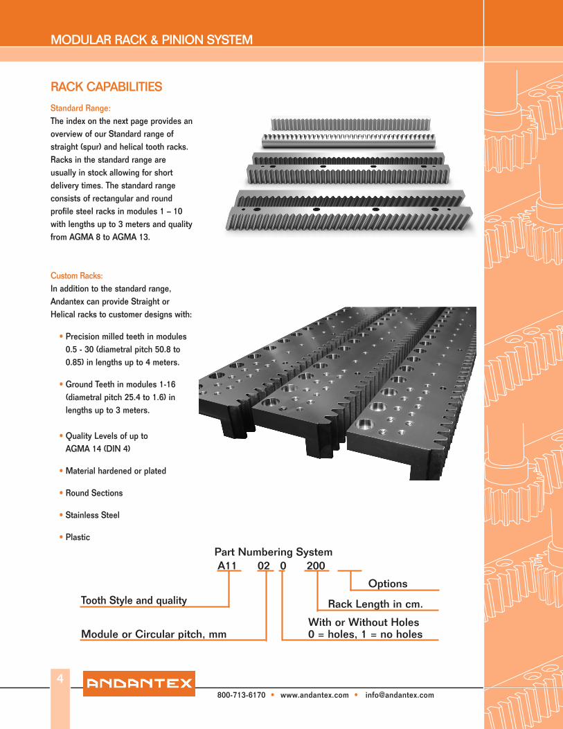
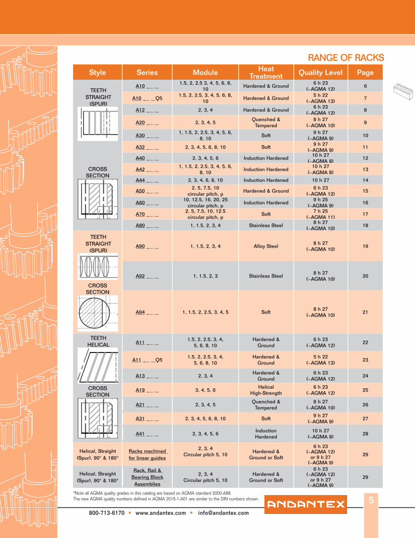
MODULAR RACK & PINION SYSTEM RACK CAPABILITIES 4 Standard Range: The index on the next page provides an overview of our Standard range of straight (spur) and helical tooth racks. Racks in the standard range are usually in stock allowing for short delivery times. The standard range consists of rectangular and round profile steel racks in modules 1 – 10 with lengths up to 3 meters and quality from AGMA 8 to AGMA 13. Custom Racks: In addition to the standard range, Andantex can provide Straight or Helical racks to customer designs with: • Precision milled teeth in modules 0.5 - 30 (diametral pitch 50.8 to 0.85) in lengths up to 4 meters. • Ground Teeth in modules 1-16 (diametral pitch 25.4 to 1.6) in lengths up to 3 meters. • Quality Levels of up to AGMA 14 (DIN 4) • Material hardened or plated • Round Sections • Stainless Steel • Plastic 800-713-6170 • www.andantex.com • [email protected] Part Numbering System A11 02 0 200 Tooth Style and quality Rack Length in cm. Module or Circular pitch, mm With or Without Holes 0 = holes, 1 = no holes Options
Transcript of MODULAR RACK & PINION SYSTEM RACK CAPABILITIES · 2016-12-05 · MODULAR RACK & PINION SYSTEM RACK...
MODULAR RACK & PINION SYSTEM
RACK CAPABILITIES
4
Standard Range:The index on the next page provides an overview of our Standard range of straight (spur) and helical tooth racks. Racks in the standard range are usually in stock allowing for short delivery times. The standard range consists of rectangular and round profile steel racks in modules 1 – 10 with lengths up to 3 meters and quality from AGMA 8 to AGMA 13.
Custom Racks:In addition to the standard range, Andantex can provide Straight or Helical racks to customer designs with:
• Precision milled teeth in modules 0.5 - 30 (diametral pitch 50.8 to 0.85) in lengths up to 4 meters.
• Ground Teeth in modules 1-16
(diametral pitch 25.4 to 1.6) in lengths up to 3 meters.
• Quality Levels of up to
AGMA 14 (DIN 4)
• Material hardened or plated • Round Sections • Stainless Steel
• Plastic
800-713-6170 • www.andantex.com • [email protected]
Part Numbering SystemA11 02 0 200
Tooth Style and quality Rack Length in cm.
Module or Circular pitch, mm With or Without Holes0 = holes, 1 = no holes
Options
MODULAR RACK & PINION SYSTEM
RANGE OF RACKS
800-713-6170 • www.andantex.com • [email protected]
Style Series Module Heat Treatment Quality Level Page
CROSSSECTION
A10 __ _ __1.5, 2, 2.5 3, 4, 5, 6, 8,
10Hardened & Ground
6 h 23(~AGMA 12)
6
A10 __ _ __Q51.5, 2, 2.5, 3, 4, 5, 6, 8,
10Hardened & Ground
5 h 22(~AGMA 13)
7
A12 __ _ __ 2, 3, 4 Hardened & Ground6 h 23
(~AGMA 12)8
A20 __ _ __ 2, 3, 4, 5Quenched &
Tempered8 h 27
(~AGMA 10)9
A30 __ _ __1, 1.5, 2, 2.5, 3, 4, 5, 6,
8, 10Soft
9 h 27(~AGMA 9)
10
A32 __ _ __ 2, 3, 4, 5, 6, 8, 10 Soft9 h 27
(~AGMA 9)11
A40 __ _ __ 2, 3, 4, 5, 6 Induction Hardened10 h 27
(~AGMA 8)12
A42 __ _ __1, 1.5, 2, 2.5, 3, 4, 5, 6,
8, 10Induction Hardened
10 h 27(~AGMA 8)
13
A44 __ _ __ 2, 3, 4, 6, 8, 10 Induction Hardened 10 h 27 14
A50 __ _ __2, 5, 7.5, 10
circular pitch, pHardened & Ground
6 h 23(~AGMA 12)
15
A60 __ _ __10, 12.5, 16, 20, 25
circular pitch, pInduction Hardened
9 h 25(~AGMA 9)
16
A70 __ _ __2, 5, 7.5, 10, 12.5 circular pitch, p
Soft7 h 25
(~AGMA 11)17
A80 __ _ __ 1, 1.5, 2, 3, 4 Stainless Steel8 h 27
(~AGMA 10)18
CROSSSECTION
A90 __ _ __ 1, 1.5, 2, 3, 4 Alloy Steel8 h 27
(~AGMA 10)19
A92 __ _ __ 1, 1.5, 2, 3 Stainless Steel8 h 27
(~AGMA 10)20
A94 __ _ __ 1, 1.5, 2, 2.5, 3, 4, 5 Soft8 h 27
(~AGMA 10)21
CROSSSECTION
A11 __ _ __1.5, 2, 2.5, 3, 4,
5, 6, 8, 10Hardened &
Ground6 h 23
(~AGMA 12)22
A11 __ _ __Q51.5, 2, 2.5, 3, 4,
5, 6, 8, 10Hardened &
Ground5 h 22
(~AGMA 13)23
A13 __ _ __ 2, 3, 4Hardened &
Ground6 h 23
(~AGMA 12)24
A19 __ _ __ 3, 4, 5, 6Helical
High-Strength6 h 23
(~AGMA 12)25
A21 __ _ __ 2, 3, 4, 5Quenched &
Tempered8 h 27
(~AGMA 10)26
A31 __ _ __ 2, 3, 4, 5, 6, 8, 10 Soft9 h 27
(~AGMA 9)27
A41 __ _ __ 2, 3, 4, 5, 6InductionHardened
10 h 27(~AGMA 8)
28
Helical, Straight (Spur), 90° & 180°
Racks machined for linear guides
2, 3, 4Circular pitch 5, 10
Hardened &Ground or Soft
6 h 23(~AGMA 12)
or 9 h 27 (~AGMA 9)
29
Helical, Straight (Spur), 90° & 180°
Rack, Rail & Bearing Block
Assemblies
2, 3, 4Circular pitch 5, 10
Hardened &Ground or Soft
6 h 23(~AGMA 12)
or 9 h 27(~AGMA 9)
29
5
TEETHSTRAIGHT
(SPUR)
TEETHSTRAIGHT
(SPUR)
TEETHHELICAL
*Note all AGMA quality grades in this catalog are based on AGMA standard 2000-A88. The new AGMA quality numbers defined in AGMA 2015-1-A01 are similar to the DIN numbers shown.

MODULAR RACK & PINION SYSTEM
800-713-6170 • www.andantex.com • [email protected]
Material AISI 1045 (C45) with tensile strength = 650 N/mm2 (95,000 PSI). Teeth induction hardened to 50-55 Rc; ground on all sides after hardening. Only teeth are hardened allowing subsequent drilling and pinning of rack. Rack ends are machined for continuous mounting.Fp is the max cumulative pitch error for the corresponding rack length.
Dimensions are in mm and are subject to change - consult factory.
SERIES A10
Module L1 l1 teeth b h ho f a l No. holes h1 d1 d2 t a1 d3 Fp mass
kg. Part no.
1.5 499.5 441.5 106 19 19 17.5 2 62.44 124.88 4 8 7 11 7 29 5.7 0.029 1.3 A10-1.50-0501.5 499.5 106 19 19 17.5 2 Without Holes 0.029 1.3 A10-1.51-0501.5 999.0 941 212 19 19 17.5 2 62.44 124.88 8 8 7 11 7 29 5.7 0.043 2.6 A10-1.50-1001.5 999.0 212 19 19 17.5 2 Without Holes 0.043 2.6 A10-1.51-1001.5 Companion Rack For Assembly A10-1.51-9992.0 502.7 440.1 80 24 24 22 2 62.83 125.66 4 8 7 11 7 31.3 5.7 2.1 A10-020-0502.0 502.7 80 24 24 22 2 Without Holes 2.1 A10-021-0502.0 1005.3 942.7 160 24 24 22 2 62.83 125.66 8 8 7 11 7 31.3 5.7 0.036 4.2 A10-020-1002.0 1005.3 160 24 24 22 2 Without Holes 0.036 4.2 A10-021-1002.0 2010.6 1948 320 24 24 22 2 62.83 125.66 16 8 7 11 7 31.3 5.7 0.058 8 A10-020-2002.0 2010.6 320 24 24 22 2 Without Holes 0.058 8 A10-021-2002.0 Companion Rack For Assembly A10-021-9992.5 502.7 440.1 64 24 24 21.5 2 62.83 125.66 4 9 7 11 7 31.3 5.7 0.027 2.0 A10-2.50-0502.5 502.7 64 24 24 21.5 2 Without Holes 0.027 2.0 A10-2.51-0502.5 1005.3 942.7 128 24 24 21.5 2 62.83 125.66 8 9 7 11 7 31.3 5.7 0.036 4.1 A10-2.50-1002.5 1005.3 128 24 24 21.5 2 Without Holes 0.036 4.1 A10-2.51-1002.5 2010.6 1948 256 24 24 21.5 2 62.83 125.66 16 9 7 11 7 31.3 5.7 0.053 8 A10-2.50-2002.5 2010.6 256 24 24 21.5 2 Without Holes 0.053 8 A10-2.51-2002.5 Companion Rack For Assembly A10-2.51-9993.0 508.9 440.1 54 29 29 26 2 63.62 127.23 4 9 10 15 9 34.4 7.7 3 A10-030-0503.0 508.9 54 29 29 26 2 Without Holes 3 A10-031-0503.0 1017.9 949.1 108 29 29 26 2 63.62 127.23 8 9 10 15 9 34.4 7.7 0.036 6 A10-030-1003.0 1017.9 108 29 29 26 2 Without Holes 0.036 6 A10-031-1003.0 2035.8 1967.0 216 29 29 26 2 63.62 127.23 16 9 10 15 9 34.4 7.7 0.055 11.5 A10-030-2003.0 2035.8 216 29 29 26 2 Without Holes 0.055 11.5 A10-031-2003.0 Companion Rack for Assembly A10-031-9994.0 502.7 427.7 40 39 39 35 3 62.83 125.66 4 12 10 15 9 37.5 7.7 5.3 A10-040-0504.0 502.7 40 39 39 35 3 Without Holes 5.3 A10-041-0504.0 1005.3 930.3 80 39 39 35 3 62.83 125.66 8 12 10 15 9 37.5 7.7 0.040 10.5 A10-040-1004.0 1005.3 80 39 39 35 3 Without Holes 0.040 10.5 A10-041-1004.0 2010.6 1935.6 160 39 39 35 3 62.83 125.66 16 12 10 15 9 37.5 7.7 21 A10-040-2004.0 2010.6 160 39 39 35 3 Without Holes 21 A10-041-2004.0 Companion Rack for Assembly A10-041-9995.0 502.6 442.4 32 49 39 34 3 62.83 125.66 4 12 14 20 13 30.1 11.7 6.7 A10-050-0505.0 502.6 32 49 39 34 3 Without Holes 6.7 A10-051-0505.0 1005.3 945 64 49 39 34 3 62.83 125.66 8 12 14 20 13 30.1 11.7 0.040 13.4 A10-050-1005.0 1005.3 64 49 39 34 3 Without Holes 0.040 13.4 A10-051-1005.0 2010.6 1950.4 128 49 39 34 3 62.83 125.66 16 12 14 20 13 30.1 11.7 26.8 A10-050-2005.0 2010.6 128 49 39 34 3 Without Holes 26.8 A10-051-2005.0 Companion Rack for Assembly A10-051-9996.0 508.9 446.1 27 59 49 43 3 63.62 127.23 4 16 18 26 17 31.4 15.7 10.1 A10-060-0506.0 508.9 27 59 49 43 3 Without Holes 10.1 A10-061-0506.0 1017.8 955 54 59 49 43 3 63.62 127.23 8 16 18 26 17 31.4 15.7 0.040 20.2 A10-060-1006.0 1017.8 54 59 49 43 3 Without Holes 0.040 20.2 A10-061-1006.0 2035.8 1973 108 59 49 43 3 63.62 127.23 16 16 18 26 17 31.4 15.7 40.4 A10-060-2006.0 2035.8 108 59 49 43 3 Without Holes 40.4 A10-061-2006.0 Companion Rack for Assembly A10-061-9998.0 502.7 449.5 20 79 79 71.0 3 62.83 125.66 4 25 22 33 21 26.6 19.7 22.4 A10-080-0508.0 502.7 20 79 79 71.0 3 Without Holes 22.4 A10-081-0508.0 1005.3 952 40 79 79 71.0 3 62.83 125.66 8 25 22 33 21 26.6 19.7 0.040 44.8 A10-080-1008.0 1005.3 40 79 79 71.0 3 Without Holes 0.040 44.8 A10-081-1008.0 2010.6 1957.3 80 79 79 71.0 3 62.83 125.66 16 25 22 33 21 26.6 19.7 89.5 A10-080-2008.0 2010.6 80 79 79 71.0 3 Without Holes 89.5 A10-081-2008.0 Companion Rack for Assembly A10-081-999
10.0 1005.3 754 32 99 99 89 3 62.83 125.66 8 32 33 48 32 125.7 19.7 0.040 69 A10-100-10010.0 1005.3 32 99 99 89 3 Without Holes 0.040 69 A10-101-10010.0 Companion Rack for Assembly A10-101-999
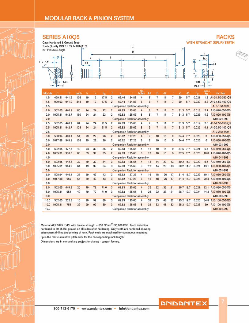
Case Hardened & Ground Teeth Tooth Quality DIN 6 h 23 (~AGMA12)
20° Pressure Angle
RACKS WITH STRAIGHT (SPUR) TEETH
6
MODULAR RACK & PINION SYSTEM
800-713-6170 • www.andantex.com • [email protected]
RACKS WITH STRAIGHT (SPUR) TEETH
No. mass
SERIES A10Q5
Material AISI 1045 (C45) with tensile strength = 650 N/mm2 (95,000 PSI). Teeth induction hardened to 50-55 Rc: ground on all sides after hardening. Only teeth are hardened allowing subsequent drilling and pinning of rack. Rack ends are machined for continuous mounting. Fp is the max cumulative pitch error for the corresponding rack length.
Dimensions are in mm and are subject to change - consult factory.
Case Hardened & Ground TeethTooth Quality DIN 5 h 22 (~AGMA13) 20° Pressure Angle
Module L1 I1 teeth b h ho f a l holes h1 d1 d2 t a1 d3 Fp kg. Part No. 1.5 499.51 441.5 106 19 19 17.5 2 62.44 124.88 4 8 7 11 7 29 5.7 0.021 1.3 A10-1.50-050-Q5 1.5 999.03 941.0 212 19 19 17.5 2 62.44 124.88 8 8 7 11 7 29 5.7 0.030 2.6 A10-1.50-100-Q5 1.5 Companion Rack for assembly A10-1.51-999 2.0 502.65 440.1 80 24 24 22 2 62.83 125.66 4 8 7 11 7 31.3 5.7 0.018 2.1 A10-020-050-Q5 2.0 1005.31 942.7 160 24 24 22 2 62.83 125.66 8 8 7 11 7 31.3 5.7 0.025 4.2 A10-020-100-Q5 2.0 Companion Rack for assembly A10-021-999 2.5 502.65 440.1 64 24 24 21.5 2 62.83 125.66 4 9 7 11 7 31.3 5.7 0.019 2.0 A10-2.50-050-Q5 2.5 1005.31 942.7 128 24 24 21.5 2 62.83 125.66 8 9 7 11 7 31.3 5.7 0.025 4.1 A10-2.50-100-Q5 2.5 Companion Rack for assembly A10-2.51-999 3.0 508.94 440.1 54 29 29 26 2 63.62 127.23 4 9 10 15 9 34.4 7.7 0.020 3 A10-030-050-Q5 3.0 1017.88 949.1 108 29 29 26 2 63.62 127.23 8 9 10 15 9 34.4 7.7 0.026 6 A10-030-100-Q5 3.0 Companion Rack for assembly A10-031-999 4.0 502.65 427.7 40 39 39 35 2 62.83 125.66 4 12 10 15 9 37.5 7.7 0.021 5.4 A10-040-050-Q5 4.0 1005.31 930.3 80 39 39 35 2 62.83 125.66 8 12 10 15 9 37.5 7.7 0.026 10.8 A10-040-100-Q5 4.0 Companion Rack for assembly A10-041-999 5.0 502.65 442.3 32 49 39 34 3 62.83 125.66 4 12 14 20 13 30.2 11.7 0.020 6.6 A10-050-050-Q5 5.0 1005.31 944.9 64 49 39 34 3 62.83 125.66 8 12 14 20 13 30.2 11.7 0.024 13.1 A10-050-100-Q5 5.0 Companion Rack for assembly A10-051-999 6.0 508.94 446.1 27 59 49 43 3 63.62 127.23 4 16 18 26 17 31.4 15.7 0.022 10.1 A10-060-050-Q5 6.0 1017.88 955 54 59 49 43 3 63.62 127.23 8 16 18 26 17 31.4 15.7 0.026 20.3 A10-060-100-Q5 6.0 Companion Rack for assembly A10-061-999 8.0 502.65 449.3 20 79 79 71.0 3 62.83 125.66 4 25 22 33 21 26.7 19.7 0.021 22.1 A10-080-050-Q5 8.0 1005.31 952 40 79 79 71.0 3 62.83 125.66 8 25 22 33 21 26.7 19.7 0.024 44.3 A10-080-100-Q5 8.0 Companion Rack for assembly A10-081-999 10.0 502.65 252.3 16 99 99 89 3 62.83 125.66 4 32 33 48 32 125.2 19.7 0.020 34.8 A10-100-050-Q5 10.0 1005.31 755 32 99 99 89 3 62.83 125.66 8 32 33 48 32 125.2 19.7 0.023 69 A10-100-100-Q5 10.0 Companion Rack for assembly A10-101-999
7
MODULAR RACK & PINION SYSTEM
800-713-6170 • www.andantex.com • [email protected]
RACKSWITH STRAIGHT (SPUR) TEETH
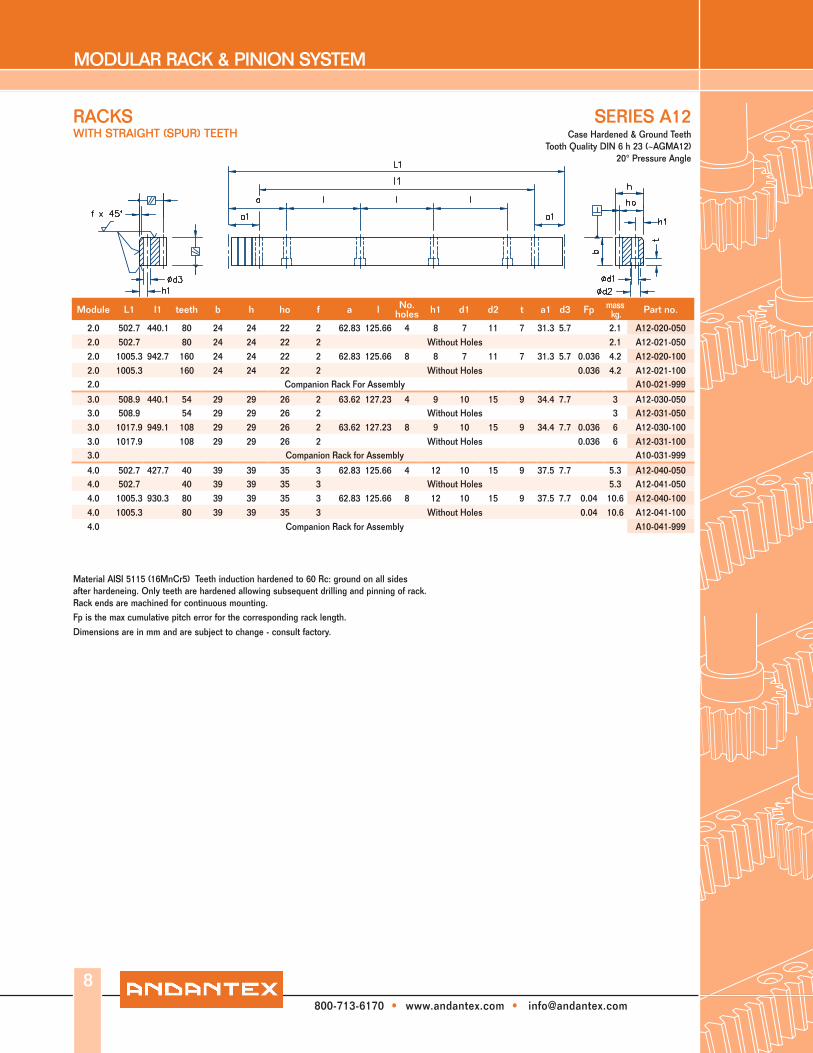
SERIES A12
Material AISI 5115 (16MnCr5) Teeth induction hardened to 60 Rc: ground on all sides after hardeneing. Only teeth are hardened allowing subsequent drilling and pinning of rack. Rack ends are machined for continuous mounting.Fp is the max cumulative pitch error for the corresponding rack length.
Dimensions are in mm and are subject to change - consult factory.
8
Module L1 l1 teeth b h ho f a l No. holes h1 d1 d2 t a1 d3 Fp mass
kg. Part no.
2.0 502.7 440.1 80 24 24 22 2 62.83 125.66 4 8 7 11 7 31.3 5.7 2.1 A12-020-0502.0 502.7 80 24 24 22 2 Without Holes 2.1 A12-021-0502.0 1005.3 942.7 160 24 24 22 2 62.83 125.66 8 8 7 11 7 31.3 5.7 0.036 4.2 A12-020-1002.0 1005.3 160 24 24 22 2 Without Holes 0.036 4.2 A12-021-1002.0 Companion Rack For Assembly A10-021-999
3.0 508.9 440.1 54 29 29 26 2 63.62 127.23 4 9 10 15 9 34.4 7.7 3 A12-030-0503.0 508.9 54 29 29 26 2 Without Holes 3 A12-031-0503.0 1017.9 949.1 108 29 29 26 2 63.62 127.23 8 9 10 15 9 34.4 7.7 0.036 6 A12-030-1003.0 1017.9 108 29 29 26 2 Without Holes 0.036 6 A12-031-1003.0 Companion Rack for Assembly A10-031-999
4.0 502.7 427.7 40 39 39 35 3 62.83 125.66 4 12 10 15 9 37.5 7.7 5.3 A12-040-0504.0 502.7 40 39 39 35 3 Without Holes 5.3 A12-041-0504.0 1005.3 930.3 80 39 39 35 3 62.83 125.66 8 12 10 15 9 37.5 7.7 0.04 10.6 A12-040-1004.0 1005.3 80 39 39 35 3 Without Holes 0.04 10.6 A12-041-1004.0 Companion Rack for Assembly A10-041-999
Case Hardened & Ground TeethTooth Quality DIN 6 h 23 (~AGMA12)
20° Pressure Angle

MODULAR RACK & PINION SYSTEM
800-713-6170 • www.andantex.com • [email protected]
RACKSWITH STRAIGHT (SPUR) TEETH
Material AISI 4140 (42CrMo4V) with tensile strength = 900 N/mm2 (130,500 PSI). Back and contact face ground. Rack ends are machined for continuous mounting.
Fp is the max cumulative pitch error for the corresponding rack length.
Dimensions are in mm and are subject to change - consult factory.
SERIES A20
9
Module L1 l1 teeth b h ho f a l No. holes h1 d1 d2 t a1 d3 Fp
mass kg. Part no.
2.0 502.7 440.1 80 24 24 22 2 62.83 125.66 4 8 7 11 7 31.3 5.7 2.2 A20-020-0502.0 502.7 80 24 24 22 2 without holes 2.2 A20-021-0502.0 1005.3 942.7 160 24 24 22 2 62.83 125.66 8 8 7 11 7 31.3 5.7 0.063 4.3 A20-020-1002.0 1005.3 160 24 24 22 2 without holes 0.063 4.3 A20-021-1002.0 2010.6 1948 320 24 24 22 2 62.83 125.66 16 8 7 11 7 31.3 5.7 8.6 A20-020-2002.0 2010.6 320 24 24 22 2 without holes 8.6 A20-021-2002.0 Companion Rack For Assembly A10-021-999-W
3.0 508.9 440.1 54 29 29 26 2 63.62 127.23 4 9 10 15 9 34.4 7.7 3.1 A20-030-0503.0 508.9 54 29 29 26 2 without holes 3.1 A20-031-0503.0 1017.9 949.1 108 29 29 26 2 63.62 127.23 8 9 10 15 9 34.4 7.7 0.071 6.2 A20-030-1003.0 1017.9 108 29 29 26 2 without holes 0.071 6.2 A20-031-1003.0 2035.8 1967 216 29 29 26 2 63.62 127.23 16 9 10 15 9 34.4 7.7 12.4 A20-030-2003.0 2035.8 216 29 29 26 2 without holes 12.4 A20-031-2003.0 Companion Rack for Assembly A10-031-999-W
4.0 502.7 427.7 40 39 39 35 3 62.83 125.66 4 12 10 15 9 37.5 7.7 5.5 A20-040-0504.0 502.7 40 39 39 35 3 without holes 5.5 A20-041-0504.0 1005.3 930.3 80 39 39 35 3 62.83 125.66 8 12 10 15 9 37.5 7.7 0.08 11 A20-040-1004.0 1005.3 80 39 39 35 3 without holes 0.08 11 A20-041-1004.0 2010.6 1935.6 160 39 39 35 3 62.83 125.66 16 12 10 15 9 37.5 7.7 22 A20-040-2004.0 2010.6 160 39 39 35 3 without holes 22 A20-041-2004.0 Companion Rack for Assembly A10-041-999-W
5.0 502.7 442.3 32 49 39 34 3 62.83 125.66 4 12 14 20 13 30.2 11.7 6.8 A20-050-0505.0 502.7 32 49 39 34 3 without holes 6.8 A20-051-0505.0 1005.3 945.0 64 49 39 34 3 62.83 125.66 8 12 14 20 13 30.2 11.7 0.08 13.6 A20-050-1005.0 1005.3 64 49 39 34 3 without holes 0.08 13.6 A20-051-1005.0 2010.6 1950.0 128 49 39 34 3 62.83 125.66 16 12 14 20 13 30.2 11.7 27.2 A20-050-2005.0 2010.6 128 49 39 34 3 without holes 27.2 A20-051-2005.0 Companion Rack for Assembly A10-051-999-W
Quenched & Tempered MaterialQuality DIN 8 h 27 (~AGMA10) 20° Pressure Angle
MODULAR RACK & PINION SYSTEM
800-713-6170 • www.andantex.com • [email protected]
RACKS WITH STRAIGHT (SPUR) TEETH
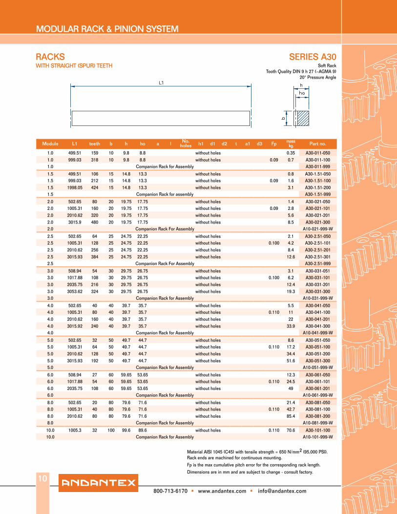
SERIES A30
Material AISI 1045 (C45) with tensile strength = 650 N/mm2 (95,000 PSI). Rack ends are machined for continuous mounting.
Fp is the max cumulative pitch error for the corresponding rack length.
Dimensions are in mm and are subject to change - consult factory.
10
Module L1 teeth b h ho a l No. holes h1 d1 d2 t a1 d3 Fp mass
kg. Part no.
1.0 499.51 159 10 9.8 8.8 without holes 0.35 A30-011-0501.0 999.03 318 10 9.8 8.8 without holes 0.09 0.7 A30-011-1001.0 Companion Rack for Assembly A30-011-999
1.5 499.51 106 15 14.8 13.3 without holes 0.8 A30-1.51-0501.5 999.03 212 15 14.8 13.3 without holes 0.09 1.6 A30-1.51-1001.5 1998.05 424 15 14.8 13.3 without holes 3.1 A30-1.51-2001.5 Companion Rack for assembly A30-1.51-999
2.0 502.65 80 20 19.75 17.75 without holes 1.4 A30-021-0502.0 1005.31 160 20 19.75 17.75 without holes 0.09 2.8 A30-021-1012.0 2010.62 320 20 19.75 17.75 without holes 5.6 A30-021-2012.0 3015.9 480 20 19.75 17.75 without holes 8.5 A30-021-3002.0 Companion Rack For Assembly A10-021-999-W
2.5 502.65 64 25 24.75 22.25 without holes 2.1 A30-2.51-0502.5 1005.31 128 25 24.75 22.25 without holes 0.100 4.2 A30-2.51-1012.5 2010.62 256 25 24.75 22.25 without holes 8.4 A30-2.51-2012.5 3015.93 384 25 24.75 22.25 without holes 12.6 A30-2.51-3012.5 Companion Rack For Assembly A30-2.51-999
3.0 508.94 54 30 29.75 26.75 without holes 3.1 A30-031-0513.0 1017.88 108 30 29.75 26.75 without holes 0.100 6.2 A30-031-1013.0 2035.75 216 30 29.75 26.75 without holes 12.4 A30-031-2013.0 3053.62 324 30 29.75 26.75 without holes 19.3 A30-031-3003.0 Companion Rack for Assembly A10-031-999-W
4.0 502.65 40 40 39.7 35.7 without holes 5.5 A30-041-0504.0 1005.31 80 40 39.7 35.7 without holes 0.110 11 A30-041-1004.0 2010.62 160 40 39.7 35.7 without holes 22 A30-041-2014.0 3015.92 240 40 39.7 35.7 without holes 33.9 A30-041-3004.0 Companion Rack for Assembly A10-041-999-W
5.0 502.65 32 50 49.7 44.7 without holes 8.6 A30-051-0505.0 1005.31 64 50 49.7 44.7 without holes 0.110 17.2 A30-051-1005.0 2010.62 128 50 49.7 44.7 without holes 34.4 A30-051-2005.0 3015.93 192 50 49.7 44.7 without holes 51.6 A30-051-3005.0 Companion Rack for Assembly A10-051-999-W
6.0 508.94 27 60 59.65 53.65 without holes 12.3 A30-061-0506.0 1017.88 54 60 59.65 53.65 without holes 0.110 24.5 A30-061-1016.0 2035.75 108 60 59.65 53.65 without holes 49 A30-061-2016.0 Companion Rack for Assembly A10-061-999-W
8.0 502.65 20 80 79.6 71.6 without holes 21.4 A30-081-0508.0 1005.31 40 80 79.6 71.6 without holes 0.110 42.7 A30-081-1008.0 2010.62 80 80 79.6 71.6 without holes 85.4 A30-081-2008.0 Companion Rack for Assembly A10-081-999-W
10.0 1005.3 32 100 99.6 89.6 without holes 0.110 70.6 A30-101-10010.0 Companion Rack for Assembly A10-101-999-W
Soft RackTooth Quality DIN 9 h 27 (~AGMA 9)
20° Pressure Angle
MODULAR RACK & PINION SYSTEM
800-713-6170 • www.andantex.com • [email protected]
Material AISI 1045 (C45) with tensile strength = 650 N/mm2 (95,000 PSI). Rack ends are machined for continuous mounting
Fp is the max cumulatve pitch error for the corresponding rack length.
Dimensions are in mm and are subject to change - consult factory.
11
Module L1 l1 teeth b h ho a l No. holes h1 d1 d2 t a1 d3 Fp mass
kg. Part no.
2.0 502.65 440.1 80 20 19.75 17.75 62.80 125.66 4 8 7 11 7 31.3 5.7 1.4 A32-020-0502.0 1005.31 942.7 160 20 19.75 17.75 62.80 125.66 8 8 7 11 7 31.3 5.7 0.090 2.8 A32-020-1002.0 2010.62 1948.0 320 20 19.75 17.75 62.80 125.66 16 8 7 11 7 31.3 5.7 5.6 A32-020-2002.0 Companion Rack for Assembly A10-021-999-W
3.0 508.94 440.1 54 30 29.75 26.75 63.60 127.23 4 9 10 15 9 34.4 7.7 3.1 A32-030-0503.0 1017.88 949.1 108 30 29.75 26.75 63.60 127.23 8 9 10 15 9 34.4 7.7 0.100 6.2 A32-030-1003.0 2035.75 1967.0 216 30 29.75 26.75 63.60 127.23 16 9 10 15 9 34.4 7.7 12.4 A32-030-2003.0 Companion Rack for Assembly A10-031-999-W
4.0 502.65 427.7 40 40 39.70 35.70 62.83 125.66 4 12 10 15 9 37.5 7.7 5.5 A32-040-0504.0 1005.31 930.3 80 40 39.70 35.70 62.83 125.66 8 12 10 15 9 37.5 7.7 0.110 11.0 A32-040-1004.0 2010.62 1935.6 160 40 39.70 35.70 62.83 125.66 16 12 10 15 9 37.5 7.7 22.0 A32-040-2004.0 Companion Rack for Assembly A10-041-999-W
5.0 502.65 442.3 32 50 49.70 44.70 62.83 125.66 4 12 14 20 13 30.2 11.7 8.6 A32-050-0505.0 1005.31 945 64 50 49.70 44.70 62.83 125.66 8 12 14 20 13 30.2 11.7 0.110 17.2 A32-050-1005.0 2010.62 1950.3 128 50 49.70 44.70 62.83 125.66 16 12 14 20 13 30.2 11.7 34.4 A32-050-2005.0 Companion Rack for Assembly A10-051-999-W
6.0 508.94 446.1 27 60 59.65 53.65 63.62 127.23 4 16 18 26 17 31.4 15.7 12.3 A32-060-0506.0 1017.88 955 54 60 59.65 53.65 63.62 127.23 8 16 18 26 17 31.4 15.7 0.110 24.5 A32-060-1006.0 2035.75 1972.9 108 60 59.65 53.65 63.62 127.23 16 16 18 26 17 31.4 15.7 49.0 A32-060-2006.0 Companion Rack for Assembly A10-061-999-W
8.0 502.65 449.5 20 80 79.60 71.60 62.83 125.66 4 25 22 33 21 26.6 19.7 21.4 A32-080-0508.0 1005.31 952.0 40 80 79.60 71.60 62.83 125.66 8 25 22 33 21 26.6 19.7 0.110 42.7 A32-080-1008.0 2010.62 1957.3 80 80 79.60 71.60 62.83 125.66 16 25 22 33 21 26.6 19.7 85.4 A32-080-2008.0 Companion Rack for Assembly A10-081-999-W
10.0 1005.31 754.0 32 100 99.60 89.60 62.83 125.66 8 32 33 48 32 125.7 19.7 0.110 70.6 A32-100-10010.0 Companion Rack for Assembly A10-101-999-W
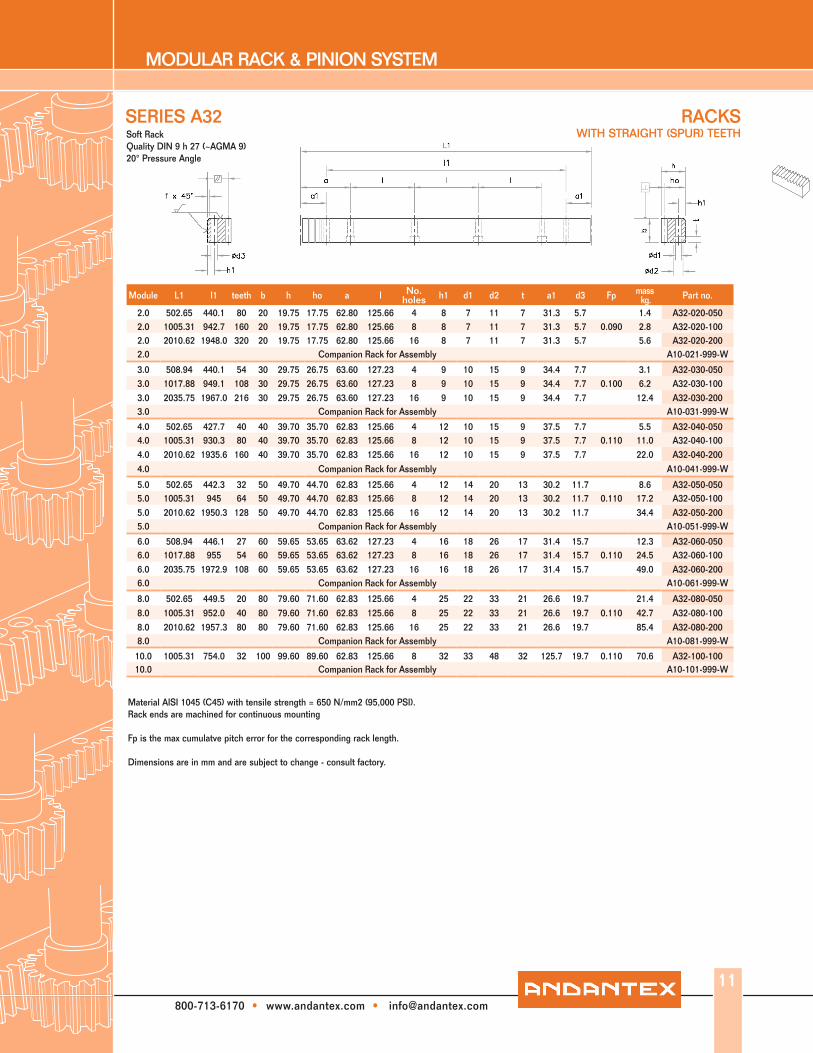
Soft RackQuality DIN 9 h 27 (~AGMA 9)20° Pressure Angle
SERIES A32 RACKSWITH STRAIGHT (SPUR) TEETH

MODULAR RACK & PINION SYSTEM
800-713-6170 • www.andantex.com • [email protected]
Material AISI 1045 (C45) with tensile strength = 650 N/mm2 (95,000 PSI). Teeth are induction hardened to 50-55Rc. Back and contact faces are machined after hardening. Only teeth are induction hardened allowing subsequent drilling and pinning of the rack. Rack ends are machined for continuous mounting.
Fp is the max cumulative pitch error for the corresponding rack length.
Dimensions are in mm and are subject to change - consult factory.
Module L1 l1 teeth b h ho f a l No. holes h1 d1 d2 t a1 d3 Fp mass
kg. Part no.
2.0 502.7 440.1 80 24 24 22 2 62.83 125.66 4 8 7 11 7 31.3 5.7 2.1 A40-020-0502.0 502.7 80 24 24 22 2 without holes 2.1 A40-021-0502.0 1005.3 942.7 160 24 24 22 2 62.83 125.66 8 8 7 11 7 31.3 5.7 0.140 4.2 A40-020-1002.0 1005.3 160 24 24 22 2 without holes 0.140 4.2 A40-021-1002.0 2010.61 1948 320 24 24 22 2 62.83 125.66 16 8 7 11 7 31.3 5.7 8.4 A40-020-2002.0 2010.61 320 24 24 22 2 without holes 8.4 A40-021-2002.0 Companion Rack For Assembly A10-021-999-W
3.0 508.9 440.1 54 29 29 26 2 63.62 127.23 4 9 10 15 9 34.4 7.7 3 A40-030-0503.0 508.9 54 29 29 26 2 without holes 3 A40-031-0503.0 1017.9 949.1 108 29 29 26 2 63.63 127.23 8 9 10 15 9 34.4 7.7 0.160 6 A40-030-1003.0 1017.9 108 29 29 26 2 without holes 0.160 6 A40-031-1003.0 2035.75 1967.0 216 29 29 26 2 63.63 127.23 16 9 10 15 9 34.4 7.7 12 A40-030-2003.0 2035.75 216 29 29 26 2 without holes 12 A40-031-2003.0 Companion Rack for Assembly A10-031-999-W
4.0 502.7 427.7 40 39 39 35 3 62.83 125.66 4 12 10 15 9 37.5 7.7 5.3 A40-040-0504.0 502.7 40 39 39 35 3 without holes 5.3 A40-041-0504.0 1005.3 930.3 80 39 39 35 3 62.83 125.66 8 12 10 15 9 37.5 7.7 0.180 10.5 A40-040-1004.0 1005.3 80 39 39 35 3 without holes 0.180 10.5 A40-041-1004.0 2010.61 1935.6 160 39 39 35 3 62.83 125.66 16 12 10 15 9 37.5 7.7 21.2 A40-040-2004.0 2010.61 160 39 39 35 3 without holes 21.2 A40-041-2004.0 Companion Rack for Assembly A10-041-999-W
5.0 502.65 442.3 32 49 39 34 3 62.83 125.66 4 12 14 20 13 30.2 11.7 6.9 A40-050-0505.0 502.65 32 49 39 34 3 without holes 6.9 A40-051-0505.0 1005.3 945 64 49 39 34 3 62.83 125.66 8 12 14 20 13 30.2 11.7 0.180 13.8 A40-050-1005.0 1005.3 64 49 39 34 3 without holes 0.180 13.8 A40-051-1005.0 2010.61 1950.3 128 49 39 34 3 62.83 125.66 16 12 14 20 13 30.2 11.7 27.6 A40-050-2005.0 2010.61 128 49 39 34 3 without holes 27.6 A40-051-2005.0 Companion Rack for Assembly A10-051-999-W
6.0 508.93 446.1 27 59 49 43 3 63.62 127.23 4 16 18 26 17 31.4 15.7 10.5 A40-060-0506.0 508.93 27 59 49 43 3 without holes 10.5 A40-061-0506.0 1017.87 955 54 59 49 43 3 63.62 127.23 8 16 18 26 17 31.4 15.7 0.180 21 A40-060-1006.0 1017.87 54 59 49 43 3 without holes 0.180 21 A40-061-1006.0 2035.75 1972.9 108 59 49 43 3 63.62 127.23 16 16 18 26 17 31.4 15.7 42 A40-060-2006.0 2035.75 108 59 49 43 3 without holes 42 A40-061-2006.0 Companion Rack for Assembly A10-061-999-W
Induction Hardened TeethQuality DIN 10 h 27 (~AGMA 8)
20° Pressure Angle
SERIES A40RACKSWITH STRAIGHT (SPUR) TEETH
12
MODULAR RACK & PINION SYSTEM
800-713-6170 • www.andantex.com • [email protected]
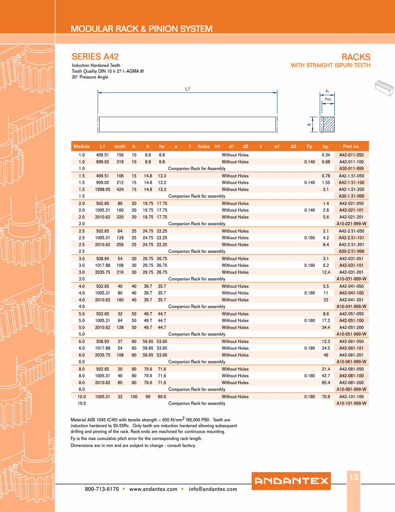
Material AISI 1045 (C45) with tensile strength = 650 N/mm2 (95,000 PSI). Teeth are induction hardened to 50-55Rc. Only teeth are induction hardened allowing subsequent drilling and pinning of the rack. Rack ends are machined for continuous mounting.Fp is the max cumulatve pitch error for the corresponding rack length.Dimensions are in mm and are subject to change - consult factory.
RACKS WITH STRAIGHT (SPUR) TEETH
SERIES A42Induction Hardened TeethTooth Quality DIN 10 h 27 (~AGMA 8)20° Pressure Angle
Module L1 teeth b h ho a l holes h1 d1 d2 t a1 d3 Fp kg. Part no.
1.0 499.51 159 10 9.8 8.8 Without Holes 0.34 A42-011-0501.0 999.02 318 10 9.8 8.8 Without Holes 0.140 0.68 A42-011-1001.0 Companion Rack for Assembly A30-011-999
1.5 499.51 106 15 14.8 13.3 Without Holes 0.78 A42-1.51-0501.5 999.02 212 15 14.8 13.3 Without Holes 0.140 1.55 A42-1.51-1001.5 1998.05 424 15 14.8 13.3 Without Holes 3.1 A42-1.51-2001.5 Companion Rack for assembly A30-1.51-999
2.0 502.65 80 20 19.75 17.75 Without Holes 1.4 A42-021-0502.0 1005.31 160 20 19.75 17.75 Without Holes 0.140 2.8 A42-021-1012.0 2010.62 320 20 19.75 17.75 Without Holes 5.6 A42-021-2012.0 Companion Rack for assembly A10-021-999-W
2.5 502.65 64 25 24.75 22.25 Without Holes 2.1 A42-2.51-0502.5 1005.31 128 25 24.75 22.25 Without Holes 0.160 4.2 A42-2.51-1012.5 2010.62 256 25 24.75 22.25 Without Holes 8.4 A42-2.51-2012.5 Companion Rack for assembly A30-2.51-999
3.0 508.94 54 30 29.75 26.75 Without Holes 3.1 A42-031-0513.0 1017.88 108 30 29.75 26.75 Without Holes 0.160 6.2 A42-031-1013.0 2035.75 216 30 29.75 26.75 Without Holes 12.4 A42-031-2013.0 Companion Rack for assembly A10-031-999-W
4.0 502.65 40 40 39.7 35.7 Without Holes 5.5 A42-041-0504.0 1005.31 80 40 39.7 35.7 Without Holes 0.180 11 A42-041-1004.0 2010.62 160 40 39.7 35.7 Without Holes 22 A42-041-2014.0 Companion Rack for assembly A10-041-999-W
5.0 502.65 32 50 49.7 44.7 Without Holes 8.6 A42-051-0505.0 1005.31 64 50 49.7 44.7 Without Holes 0.180 17.2 A42-051-1005.0 2010.62 128 50 49.7 44.7 Without Holes 34.4 A42-051-2005.0 Companion Rack for assembly A10-051-999-W
6.0 508.93 27 60 59.65 53.65 Without Holes 12.3 A42-061-0506.0 1017.88 54 60 59.65 53.65 Without Holes 0.180 24.5 A42-061-1016.0 2035.75 108 60 59.65 53.65 Without Holes 49 A42-061-2016.0 Companion Rack for assembly A10-061-999-W
8.0 502.65 20 80 79.6 71.6 Without Holes 21.4 A42-081-0508.0 1005.31 40 80 79.6 71.6 Without Holes 0.180 42.7 A42-081-1008.0 2010.62 80 80 79.6 71.6 Without Holes 85.4 A42-081-2008.0 Companion Rack for assembly A10-081-999-W
10.0 1005.31 32 100 99 89.6 Without Holes 0.180 70.6 A42-101-10010.0 Companion Rack for assembly A10-101-999-W
13
MODULAR RACK & PINION SYSTEM
800-713-6170 • www.andantex.com • [email protected]
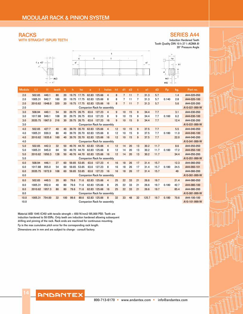
Material AISI 1045 (C45) with tensile strength = 650 N/mm2 (95,000 PSI). Teeth are induction hardened to 50-55Rc. Only teeth are induction hardened allowing subsequent drilling and pinning of the rack. Rack ends are machined for continuous mounting.Fp is the max cumulatve pitch error for the corresponding rack length.Dimensions are in mm and are subject to change - consult factory.
RACKS WITH STRAIGHT (SPUR) TEETH
SERIES A44Induction Hardened Teeth
Tooth Quality DIN 10 h 27 (~AGMA 8)20° Pressure Angle
Module L1 l1 teeth b h ho a l holes h1 d1 d2 t a1 d3 Fp kg. Part no.
2.0 502.65 440.1 80 20 19.75 17.75 62.83 125.66 4 8 7 11 7 31.3 5.7 1.4 A44-020-0502.0 1005.31 942.7 160 20 19.75 17.75 62.83 125.66 8 8 7 11 7 31.3 5.7 0.140 2.8 A44-020-1002.0 2010.62 1948.0 320 20 19.75 17.75 62.83 125.66 16 8 7 11 7 31.3 5.7 5.6 A44-020-2002.0 Companion Rack for assembly A10-021-999-W
3.0 508.94 440.1 54 30 29.75 26.75 63.6 127.23 4 9 10 15 9 34.4 7.7 3.1 A44-030-0503.0 1017.88 949.1 108 30 29.75 26.75 63.6 127.23 8 9 10 15 9 34.4 7.7 0.160 6.2 A44-030-1003.0 2035.75 1967.0 216 30 29.75 26.75 63.6 127.23 16 9 10 15 9 34.4 7.7 12.4 A44-030-2003.0 Companion Rack for assembly A10-031-999-W
4.0 502.65 427.7 40 40 39.70 35.70 62.83 125.66 4 12 10 15 9 37.5 7.7 5.5 A44-040-0504.0 1005.31 930.3 80 40 39.70 35.70 62.83 125.66 8 12 10 15 9 37.5 7.7 0.180 11.0 A44-040-1004.0 2010.62 1935.6 160 40 39.70 35.70 62.83 125.66 16 12 10 15 9 37.5 7.7 22.0 A44-040-2004.0 Companion Rack for assembly A10-041-999-W
5.0 502.65 442.3 32 50 49.70 44.70 62.83 125.66 4 12 14 20 13 30.2 11.7 8.6 A44-050-0505.0 1005.31 945.0 64 50 49.70 44.70 62.83 125.66 8 12 14 20 13 30.2 11.7 0.180 17.2 A44-050-1005.0 2010.62 1950.3 128 50 49.70 44.70 62.83 125.66 16 12 14 20 13 30.2 11.7 34.4 A44-050-2005.0 Companion Rack for assembly A10-051-999-W
6.0 508.94 446.1 27 60 59.65 53.65 63.6 127.23 4 16 18 26 17 31.4 15.7 12.3 A44-060-0506.0 1017.88 955.0 54 60 59.65 53.65 63.6 127.23 8 16 18 26 17 31.4 15.7 0.180 24.5 A44-060-1016.0 2035.75 1972.9 108 60 59.65 53.65 63.6 127.23 16 16 18 26 17 31.4 15.7 49 A44-060-2006.0 Companion Rack for assembly A10-061-999-W
8.0 502.65 449.5 20 80 79.6 71.6 62.83 125.66 4 25 22 33 21 26.6 19.7 21.4 A44-080-050
8.0 1005.31 952.0 40 80 79.6 71.6 62.83 125.66 8 25 22 33 21 26.6 19.7 0.180 42.7 A44-080-1008.0 2010.62 1957.3 80 80 79.6 71.6 62.83 125.66 16 25 22 33 21 26.6 19.7 85.4 A44-080-2008.0 Companion Rack for assembly A10-081-999-W
10.0 1005.31 754.00 32 100 99.6 89.6 62.83 125.66 8 32 33 48 32 125.7 19.7 0.180 70.6 A44-100-10010.0 Companion Rack for assembly A10-101-999-W
14

MODULAR RACK & PINION SYSTEM
800-713-6170 • www.andantex.com • [email protected]
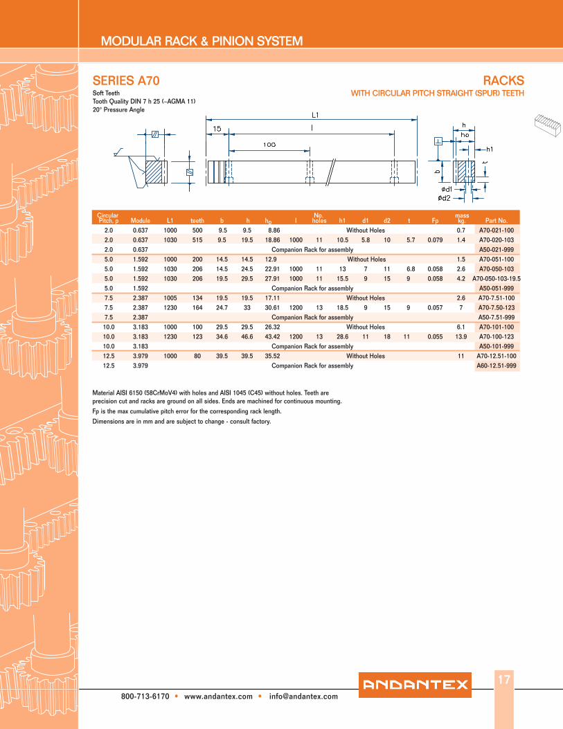
RACKS WITH CIRCULAR PITCH STRAIGHT (SPUR) TEETH
SERIES A50
Material AISI 6150 (58CrMoV4). Teeth induction hardened to 50-60 Rc: ground on all sides after hardening. Only teeth are hardened allowing subsequent drilling and pinning of rack. Rack ends are machined for continuous mounting.
Fp is the max cumulative pitch error for the corresponding rack length.
Dimensions are in mm and are subject to change - consult factory.
No. mass Pitch, p Module L1 I teeth b h ho holes h1 d1 d2 t Fp kg. Part No. 2.0 0.637 330 300 165 9.5 19.5 18.86 3 10.5 5.8 10 5.7 0.032 0.45 A50-020-033 2.0 0.637 1030 1000 515 9.5 19.5 18.86 10 10.5 5.8 10 5.7 0.068 1.4 A50-020-103 2.0 0.637 Companion Rack for assembly A50-021-999 5.0 1.592 330 300 66 14.5 24.5 22.91 3 13 7 11 6.8 0.023 0.85 A50-050-033 5.0 1.592 1030 1000 206 14.5 24.5 22.91 10 13 7 11 6.8 0.043 2.6 A50-050-103 5.0 1.592 330 300 66 19.5 29.5 27.91 3 15.5 9 15 9 0.023 1.35 A50-050-033-19.5 5.0 1.592 1030 1000 206 19.5 29.5 27.91 10 15.5 9 15 9 0.043 4.2 A50-050-103-19.5 5.0 Companion Rack for assembly A50-051-999 7.5 2.387 330 300 44 24.7 33 30.61 3 18.5 9 15 9 0.024 1.9 A50-7.50-033 7.5 2.387 1230 1200 164 24.7 33 30.61 12 18.5 9 15 9 0.041 7 A50-7.50-123 7.5 2.387 Companion Rack for assembly A50-7.51-999 10.0 3.183 330 300 33 34.6 46.6 43.42 3 28.6 11 18 11 0.025 3.7 A50-100-033 10.0 3.183 1230 1200 123 34.6 46.6 43.42 12 28.6 11 18 11 0.04 13.9 A50-100-123 10.0 3.183 Companion Rack for assembly A50-101-999
Circular
Case Hardened & Ground TeethQuality DIN 6 h 23 (~AGMA12) 20° Pressure Angle
15

MODULAR RACK & PINION SYSTEM
800-713-6170 • www.andantex.com • [email protected]
RACKSWITH CIRCULAR PITCH STRAIGHT (SPUR) TEETH
Material AISI 1045 (C45) with tensile strength = 650 N/mm2 (95,000 PSI). Teeth are induction hardened to 50-55Rc. Back and contact faces are machined after hardening. Only teeth are induction hardened allowing subsequent drilling and pinning of the rack. Rack ends are machined for continuous mounting.
Fp is the max cumulative pitch error for the corresponding rack length.
Dimensions are in mm and are subject to change - consult factory.
SERIES A60
No. massCircular Pitch, p Module L1 I teeth b h ho holes h1 d1 d2 t Fp kg. Part No. 10.0 3.183 800 700 80 29 29 25.82 10 11.5 9 15 9 0.092 4.8 A60-100-080 10.0 3.183 1200 1100 120 29 29 25.82 14 11.5 9 15 9 0.108 7.2 A60-100-120 10.0 3.183 2000 1900 200 29 29 25.82 22 11.5 9 15 9 0.142 12 A60-100-200 10.0 3.183 Companion Rack for assembly A50-101-999 12.5 3.979 800 700 64 39 39 35.02 10 14 11 18 11 0.094 9.8 A60-12.50-080 12.5 3.979 1200 1100 96 39 39 35.02 14 14 11 18 11 0.108 13.5 A60-12.50-120 12.5 3.979 2000 1900 160 39 39 35.02 22 14 11 18 11 0.137 22.5 A60-12.50-200 12.5 3.979 Companion Rack for assembly A60-12.51-999 16.0 5.093 800 700 50 49 49 43.91 10 24 13.5 20 13 0.088 14.2 A60-160-080 16.0 5.093 1200 1100 75 49 49 43.91 14 24 13.5 20 13 0.099 21.2 A60-160-120 16.0 5.093 2000 1900 125 49 49 43.91 22 24 13.5 20 13 0.121 35.3 A60-160-200 16.0 5.093 Companion Rack for assembly A60-161-999 20.0 6.366 800 700 40 59 59 52.63 10 29 13.5 20 13 0.094 20.2 A60-200-080 20.0 6.366 1200 1100 60 59 59 52.63 14 29 13.5 20 13 0.104 30.3 A60-200-120 20.0 6.366 2000 1900 100 59 59 52.63 22 29 13.5 20 13 0.125 50.5 A60-200-200 20.0 6.366 Companion Rack for assembly A60-201-999 25.0 7.958 800 700 32 79 79 71.04 10 39 17.5 26 17.5 0.09 35.7 A60-250-080 25.0 7.958 1200 1100 48 79 79 71.04 14 39 17.5 26 17.5 0.098 53.6 A60-250-120 25.0 7.958 2000 1900 80 79 79 71.04 22 39 17.5 26 17.5 0.115 89.3 A60-250-200 25.0 7.958 Companion Rack for assembly A60-251-999
16
Induction Hardened TeethQuality DIN 9 h 25 (~AGMA 9)
20° Pressure Angle
MODULAR RACK & PINION SYSTEM
800-713-6170 • www.andantex.com • [email protected]
SERIES A70
Material AISI 6150 (58CrMoV4) with holes and AISI 1045 (C45) without holes. Teeth areprecision cut and racks are ground on all sides. Ends are machined for continuous mounting.
Fp is the max cumulative pitch error for the corresponding rack length.
Dimensions are in mm and are subject to change - consult factory.
No. mass Pitch, p Module L1 teeth b h ho l holes h1 d1 d2 t Fp kg. Part No. 2.0 0.637 1000 500 9.5 9.5 8.86 Without Holes 0.7 A70-021-100 2.0 0.637 1030 515 9.5 19.5 18.86 1000 11 10.5 5.8 10 5.7 0.079 1.4 A70-020-103 2.0 0.637 Companion Rack for assembly A50-021-999 5.0 1.592 1000 200 14.5 14.5 12.9 Without Holes 1.5 A70-051-100 5.0 1.592 1030 206 14.5 24.5 22.91 1000 11 13 7 11 6.8 0.058 2.6 A70-050-103 5.0 1.592 1030 206 19.5 29.5 27.91 1000 11 15.5 9 15 9 0.058 4.2 A70-050-103-19.5 5.0 1.592 Companion Rack for assembly A50-051-999 7.5 2.387 1005 134 19.5 19.5 17.11 Without Holes 2.6 A70-7.51-100 7.5 2.387 1230 164 24.7 33 30.61 1200 13 18.5 9 15 9 0.057 7 A70-7.50-123 7.5 2.387 Companion Rack for assembly A50-7.51-999 10.0 3.183 1000 100 29.5 29.5 26.32 Without Holes 6.1 A70-101-100 10.0 3.183 1230 123 34.6 46.6 43.42 1200 13 28.6 11 18 11 0.055 13.9 A70-100-123 10.0 3.183 Companion Rack for assembly A50-101-999 12.5 3.979 1000 80 39.5 39.5 35.52 Without Holes 11 A70-12.51-100 12.5 3.979 Companion Rack for assembly A60-12.51-999
Circular
RACKS WITH CIRCULAR PITCH STRAIGHT (SPUR) TEETH
17
Soft TeethTooth Quality DIN 7 h 25 (~AGMA 11)20° Pressure Angle

MODULAR RACK & PINION SYSTEM
800-713-6170 • www.andantex.com • [email protected]
RACKSWITH STRAIGHT (SPUR) TEETH Stainless Steel, Soft Rack
Tooth Quality DIN 8 h 27 (~AGMA 10)20° Pressure Angle
SERIES A80
Material AISI 303 (X8CrNiS 18-9). Rack ends are machined for continuous mounting.Fp is the max cumulatve pitch error for the corresponding rack length.Dimensions are in mm and are subject to change - consult factory.
18
Module L1 teeth b h ho a lNo.
holes h1 d1 d2 t a1 d3 Fpmass kg. Part no.
1.0 499.51 159 10 9.80 8.80 Without Holes 0.34 A80-011-0501.0 999.03 318 10 9.80 8.80 Without Holes 0.68 A80-011-1001.0 Companion Rack for Assembly A30-011-999
1.5 499.51 106 15 14.80 13.30 Without Holes 0.8 A80-1.51-0501.5 999.03 212 15 14.80 13.30 Without Holes 1.6 A80-1.51-1001.5 Companion Rack for assembly A30-1.51-999
2.0 502.65 80 20 19.75 17.75 Without Holes 1.4 A80-021-0502.0 999.03 159 20 19.75 17.75 Without Holes 2.8 A80-021-1002.0 1998.05 318 20 19.75 17.75 Without Holes 5.6 A80-021-2002.0 Companion Rack For Assembly A10-021-999-W
3.0 499.51 53 30 29.75 26.75 Without Holes 3.1 A80-031-0503.0 999.03 106 30 29.75 26.75 Without Holes 6.2 A80-031-1003.0 1998.05 212 30 29.75 26.75 Without Holes 12.4 A80-031-2003.0 Companion Rack for Assembly A10-031-999-W
4.0 1005.31 80 40 39.70 35.70 Without Holes 11 A80-041-1004.0 1998.05 159 40 39.70 35.70 Without Holes 22 A80-041-2004.0 Companion Rack for Assembly A10-041-999-W
MODULAR RACK & PINION SYSTEM
800-713-6170 • www.andantex.com • [email protected]
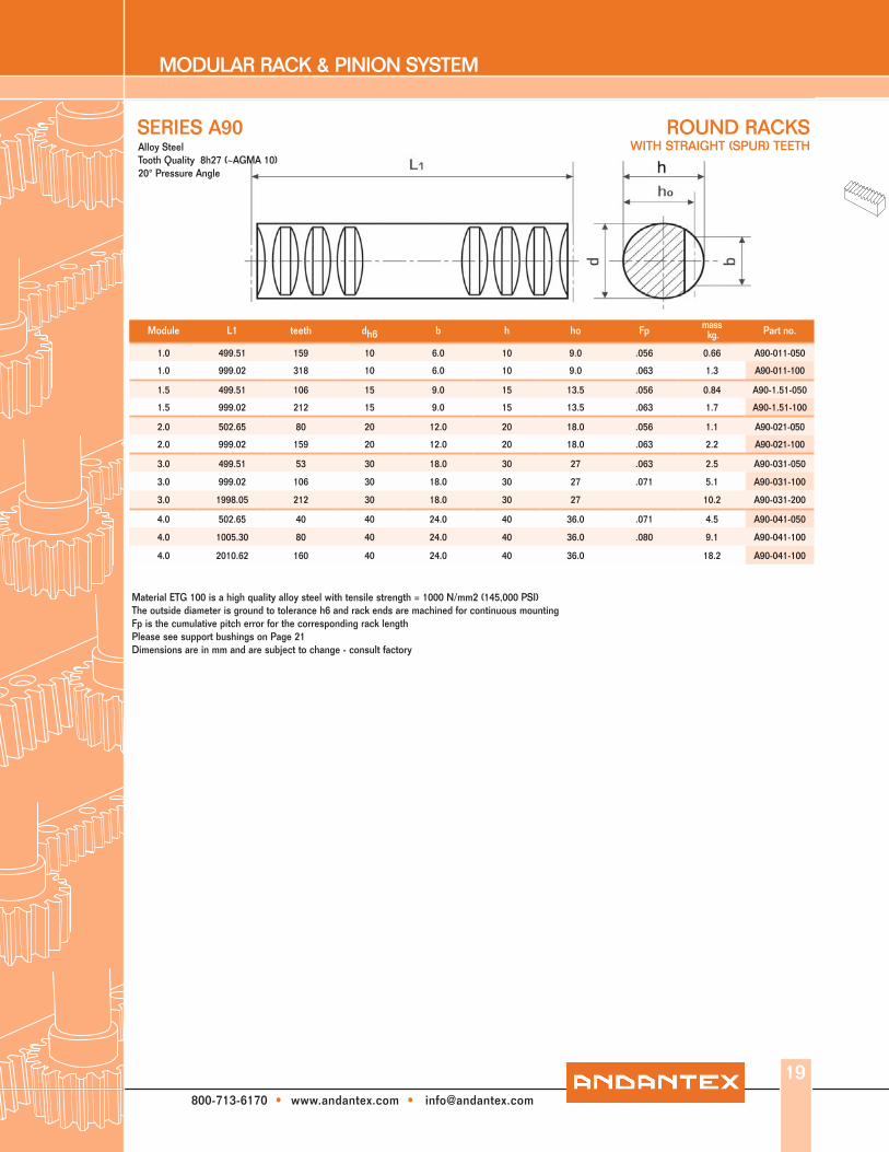
Material ETG 100 is a high quality alloy steel with tensile strength = 1000 N/mm2 (145,000 PSI)The outside diameter is ground to tolerance h6 and rack ends are machined for continuous mountingFp is the cumulative pitch error for the corresponding rack lengthPlease see support bushings on Page 21Dimensions are in mm and are subject to change - consult factory
SERIES A90
19
Module L1 teeth dh6 b h ho Fp mass kg. Part no.
1.0 499.51 159 10 6.0 10 9.0 .056 0.66 A90-011-050
1.0 999.02 318 10 6.0 10 9.0 .063 1.3 A90-011-100
1.5 499.51 106 15 9.0 15 13.5 .056 0.84 A90-1.51-050
1.5 999.02 212 15 9.0 15 13.5 .063 1.7 A90-1.51-100
2.0 502.65 80 20 12.0 20 18.0 .056 1.1 A90-021-050
2.0 999.02 159 20 12.0 20 18.0 .063 2.2 A90-021-100
3.0 499.51 53 30 18.0 30 27 .063 2.5 A90-031-050
3.0 999.02 106 30 18.0 30 27 .071 5.1 A90-031-100
3.0 1998.05 212 30 18.0 30 27 10.2 A90-031-200
4.0 502.65 40 40 24.0 40 36.0 .071 4.5 A90-041-050
4.0 1005.30 80 40 24.0 40 36.0 .080 9.1 A90-041-100
4.0 2010.62 160 40 24.0 40 36.0 18.2 A90-041-100
Alloy SteelTooth Quality 8h27 (~AGMA 10)20° Pressure Angle
ROUND RACKSWITH STRAIGHT (SPUR) TEETH

MODULAR RACK & PINION SYSTEM
800-713-6170 • www.andantex.com • [email protected]
Material AISI 303 (X8CrNiS 18-9)The outside diameter tolerance is h9 and rack ends are machined for continuous mountingFp is the cumulative pitch error for the corresponding rack lengthPlease see support bushings on page 21Dimensions are in mm and are subject to change - consult factory
SERIES A92
Module L1 teeth dh9 b h ho Fp mass kg. Part no.
1.0 499.51 159 10 6.2 10 9.0 .056 0.66 A92-011-050
1.0 999.02 318 10 6.2 10 9.0 .063 1.3 A92-011-100
1.5 499.51 106 15 9.3 15 13.5 .056 0.84 A92-1.51-050
1.5 999.02 212 15 9.3 15 13.5 .063 1.7 A92-1.51-100
2.0 502.65 80 20 12.5 20 18.0 .056 1.1 A92-021-050
2.0 999.02 159 20 12.5 20 18.0 .063 2.2 A92-021-100
3.0 499.51 53 30 18.5 30 27 .063 2.5 A92-031-050
3.0 999.02 106 30 18.5 30 27 .071 5.1 A92-031-100
Stainless SteelTooth Quality 8h27 (~AGMA 10)
20° Pressure Angle
ROUND RACKSWITH STRAIGHT (SPUR) TEETH
20

MODULAR RACK & PINION SYSTEM
800-713-6170 • www.andantex.com • [email protected]
Material AISI 1045 (C45) with tensile strength = 650 N/mm2 (95,000 PSI)The outside diameter tolerance h11 and rack ends are machined for continuous mountingFp is the cumulative pitch error for the corresponding rack lengthSee Support bushings below.
SERIES A94
Module L1 teeth dh11 b h ho Fp mass kg. Part no.
1.0 499.51 159 15 7.5 15 14.0 .056 0.66 A94-011-050
1.0 999.02 318 15 7.5 15 14.0 .063 1.3 A94-011-100
1.5 499.51 106 17 9.6 17 15.5 .056 0.84 A94-1.51-050
1.5 999.02 212 17 9.6 17 15.5 .063 1.7 A94-1.51-100
2.0 502.65 80 20 12.0 20 18.0 .056 1.1 A94-021-050
2.0 999.02 159 20 12.0 20 18.0 .063 2.2 A94-021-100
2.5 502.65 64 25 15.0 25 22.5 .056 1.8 A94-2.51-050
2.5 997.45 127 25 15.0 25 22.5 .063 3.6 A94-2.51-100
3.0 499.51 53 30 18.0 30 27.0 .063 2.5 A94-031-050
3.0 999.02 106 30 18.0 30 27.0 .071 5.1 A94-031-100
4.0 502.65 40 40 24.0 40 36.0 .071 4.5 A94-041-050
4.0 1005.30 80 40 24.0 40 36.0 .080 9.1 A94-041-100
5.0 502.65 32 50 30.0 50 45.0 .071 7.1 A94-051-050
5.0 1005.30 64 50 30.0 50 45.0 .080 14.3 A94-051-100
5.0 2010.60 128 50 30.0 50 45.0 28.6 A94-051-200
SoftTooth Quality 8h27 (~AGMA 10)20° Pressure Angle
ROUND RACKSWITH STRAIGHT (SPUR) TEETH
21
d1* d2 r7 d3 b1 b2 (kg) Part no.
10 16 22 3 16 0.02 141-010-000
15 21 26 3 16 0.03 141-015-000
20 26 32 3 25 0.04 141-020-000
30 38 46 4 30 0.11 141-030-000
40 50 60 5 50 0.27 141-040-000
50 60 70 5 63 0.58 141-050-000
Oil Impregnated bronze bushings with MoS2 providing nearly maintenancefree round rack supports
SUPPORT BUSHINGS
* For Ød1 = 10 - 40 mm - tolerance = E7; For Ød1 = 50 mm - tolerance E8Dimensions are in mm and are subject to change - consult factory

MODULAR RACK & PINION SYSTEM
800-713-6170 • www.andantex.com • [email protected]
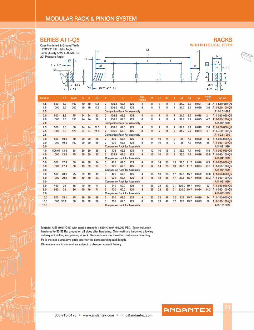
Material AISI 1045 (C45) with tensile strength = 650 N/mm2 (95,000 PSI). Teeth induction hardened to 50-55 Rc; ground on all sides after hardening. Only teeth are hardened allowing subsequent drilling and pinning of rack. Rack ends are machined for continuous mounting.Fp is the max cumulatve pitch error for the corresponding rack length.Dimensions are in mm and are subject to change - consult factory.
SERIES A11
Module L1 L2 teeth b h ho f l1 a l No. holes h1 d1 d2 t a1 d3 Fp
mass kg. Part no.
1.5 500 6.7 100 19 19 17.5 2 436.6 62.5 125 4 8 7 11 7 31.7 5.7 0.029 1.3 A11-1.50-0501.5 500 6.7 100 19 19 17.5 2 Without Holes 0.029 1.3 A11-1.51-0501.5 1000 6.7 200 19 19 17.5 2 936.6 62.5 125 8 8 7 11 7 31.7 5.7 0.043 2.6 A11-1.50-1001.5 1000 6.7 200 19 19 17.5 2 Without Holes 0.043 2.6 A11-1.51-1001.5 Companion Rack For Assembly A11-1.51-9992.0 500 8.5 75 24 24 22 2 436.6 62.5 125 4 8 7 11 7 31.7 5.7 2.1 A11-020-0502.0 500 8.5 75 24 24 22 2 Without Holes 2.1 A11-021-0502.0 1000 8.5 150 24 24 22 2 936.6 62.5 125 8 8 7 11 7 31.7 5.7 0.036 4.2 A11-020-1002.0 1000 8.5 150 24 24 22 2 Without Holes 0.036 4.2 A11-021-1002.0 2000 8.5 300 24 24 22 2 1936.6 62.5 125 16 8 7 11 7 31.7 5.7 0.058 8.2 A11-020-2002.0 2000 8.5 300 24 24 22 2 Without Holes 0.058 8.2 A11-021-2002.0 Companion Rack For Assembly A11-021-9992.5 500 8.5 60 24 24 21.5 2 436.6 62.5 125 4 9 7 11 7 31.7 5.7 0.027 2.0 A11-2.50-0502.5 500 8.5 60 24 24 21.5 2 Without Holes 0.027 2.0 A11-2.51-0502.5 1000 8.5 120 24 24 21.5 2 936.6 62.5 125 8 9 7 11 7 31.7 5.7 0.036 4.1 A11-2.50-1002.5 1000 8.5 120 24 24 21.5 2 Without Holes 0.036 4.1 A11-2.51-1002.5 2000 8.5 240 24 24 21.5 2 1936.6 62.5 125 16 9 7 11 7 31.7 5.7 0.053 8.2 A11-2.50-2002.5 2000 8.5 240 24 24 21.5 2 Without Holes 0.053 8.2 A11-2.51-2002.5 Companion Rack For Assembly A11-2.51-9993.0 500 10.3 50 29 29 26 2 430 62.5 125 4 9 10 15 9 35 7.7 2.9 A11-030-0503.0 500 10.3 50 29 29 26 2 Without Holes 2.9 A11-031-0503.0 1000 10.3 100 29 29 26 2 930 62.5 125 8 9 10 15 9 35 7.7 0.036 5.9 A11-030-1003.0 1000 10.3 100 29 29 26 2 Without Holes 0.036 5.9 A11-031-1003.0 2000 10.3 200 29 29 26 2 1930 62.5 125 16 9 10 15 9 35 7.7 0.054 11.2 A11-030-2003.0 2000 10.3 200 29 29 26 2 Without Holes 0.054 11.2 A11-031-2003.0 2 A11-031-9994.0 506.67 13.8 38 39 39 35 3 433.0 62.5 125 4 12 10 15 9 33.3 7.7 5.4 A11-040-0504.0 506.67 13.8 38 39 39 35 3 Without Holes 5.4 A11-041-0504.0 1000 13.8 75 39 39 35 3 933.4 62.5 125 8 12 10 15 9 33.3 7.7 0.040 10.7 A11-040-1004.0 1000 13.8 75 39 39 35 3 Without Holes 0.040 10.7 A11-041-1004.0 2000 13.8 150 39 39 35 3 1933.4 62.5 125 16 12 10 15 9 33.3 7.7 21.4 A11-040-2004.0 2000 13.8 150 39 39 35 3 Without Holes 21.4 A11-041-2004.0 Companion Rack for Assembly A11-041-9995.0 500 17.4 30 49 39 34 3 425 62.5 125 4 12 14 20 13 37.5 11.7 6.5 A11-050-0505.0 500 17.4 30 49 39 34 3 Without Holes 6.5 A11-051-0505.0 1000 17.4 60 49 39 34 3 925 62.5 125 8 12 14 20 13 37.5 11.7 0.040 13 A11-050-1005.0 1000 17.4 60 49 39 34 3 Without Holes 0.040 13 A11-051-1005.0 2000 17.4 120 49 39 34 3 1925 62.5 125 16 12 14 20 13 37.5 11.7 26 A11-050-2005.0 2000 17.4 120 49 39 34 3 Without Holes 26 A11-051-2005.0 Companion Rack for Assembly A11-051-9996.0 500 20.9 25 59 49 43 3 425 62.5 125 4 16 18 26 17 37.5 15.7 9.9 A11-060-0506.0 500 20.9 25 59 49 43 3 Without Holes 9.9 A11-061-0506.0 1000 20.9 50 59 49 43 3 925 62.5 125 8 16 18 26 17 37.5 15.7 0.040 19.8 A11-060-1006.0 1000 20.9 50 59 49 43 3 Without Holes 0.040 19.8 A11-061-1006.0 2000 20.9 100 59 49 43 3 1925 62.5 125 16 16 18 26 17 37.5 15.7 36.2 A11-060-2006.0 2000 20.9 100 59 49 43 3 Without Holes 36.2 A11-061-2006.0 Companion Rack for Assembly A11-061-9998.0 480 28 18 79 79 71 3 240 60.0 120 4 25 22 33 21 120.0 19.7 21 A11-080-0508.0 480 28 18 79 79 71 3 Without Holes 21 A11-081-0508.0 960 28 36 79 79 71 3 720 60.0 120 8 25 22 33 21 120.0 19.7 0.040 42.5 A11-080-1008.0 960 28 36 79 79 71 3 Without Holes 0.040 42.5 A11-081-1008.0 1920 28 72 79 79 71 3 1680 60.0 120 16 25 22 33 21 120 19.7 85 A11-080-2008.0 1920 28 72 79 79 71 3 Without Holes 85 A11-081-2008.0 Companion Rack for Assembly A11-081-99910.0 1000 35.11 30 99 99 89 3 750 62.5 125 8 32 33 48 32 125 19.7 0.040 69 A11-100-10010.0 1000 35.11 30 99 99 89 3 Without Holes 0.040 69 A11-101-10010.0 Companion Rack for Assembly A11-101-999
Case Hardened & Ground Teeth 19°31'42" R.H. Helix Angle
Tooth Quality DIN 6 h 23 (~AGMA12) 20° Pressure Angle
RACKSWITH RH HELICAL TEETH
22
MODULAR RACK & PINION SYSTEM
800-713-6170 • www.andantex.com • [email protected]
Material AISI 1045 (C45) with tensile strength = 650 N/mm2 (95,000 PSI). Teeth induction hardened to 50-55 Rc; ground on all sides after hardening. Only teeth are hardened allowing subsequent drilling and pinning of rack. Rack ends are machined for continuous mounting.
Fp is the max cumulative pitch error for the corresponding rack length.
Dimensions are in mm and are subject to change - consult factory.
SERIES A11-Q5
Module L1 L2 teeth b h ho f l1 a l No. holes h1 d1 d2 t a1 d3 Fp mass
kg. Part no.
1.5 500 6.7 100 19 19 17.5 2 436.6 62.5 125 4 8 7 11 7 31.7 5.7 0.021 1.3 A11-1.50-050-Q51.5 1000 6.7 200 19 19 17.5 2 936.6 62.5 125 8 8 7 11 7 31.7 5.7 0.030 2.6 A11-1.50-100-Q51.5 Companion Rack For Assembly A11-1.51-9992.0 500 8.5 75 24 24 22 2 436.6 62.5 125 4 8 7 11 7 31.7 5.7 0.018 2.1 A11-020-050-Q52.0 1000 8.5 150 24 24 22 2 936.6 62.5 125 8 8 7 11 7 31.7 5.7 0.025 4.2 A11-020-100-Q52.0 Companion Rack For Assembly A11-021-9992.5 500 8.5 60 24 24 21.5 2 436.6 62.5 125 4 9 7 11 7 31.7 5.7 0.019 2.0 A11-2.50-050-Q52.5 1000 8.5 120 24 24 21.5 2 936.6 62.5 125 8 9 7 11 7 31.7 5.7 0.024 4.1 A11-2.50-100-Q52.5 Companion Rack For Assembly A11-2.51-9993.0 500 10.3 50 29 29 26 2 430 62.5 125 4 9 10 15 9 35 7.7 0.020 3 A11-030-050-Q53.0 1000 10.3 100 29 29 26 2 930 62.5 125 8 9 10 15 9 35 7.7 0.026 68 A11-030-100-Q53.0 Companion Rack for Assembly A11-031-9994.0 506.67 13.8 38 39 39 35 3 433 62.5 125 4 12 10 15 9 33.3 7.7 0.021 5.4 A11-040-050-Q54.0 1000 13.8 75 39 39 35 3 933.4 62.5 125 8 12 10 15 9 33.3 7.7 0.026 10.8 A11-040-100-Q54.0 Companion Rack for Assembly A11-041-9995.0 500 17.4 30 49 39 34 3 425 62.5 125 4 12 14 20 13 37.5 11.7 0.020 6.5 A11-050-050-Q55.0 1000 17.4 60 49 39 34 3 925 62.5 125 8 12 14 20 13 37.5 11.7 0.024 13.1 A11-050-100-Q55.0 Companion Rack for Assembly A11-051-9996.0 500 20.9 25 59 49 43 3 425 62.5 125 4 16 18 26 17 37.5 15.7 0.022 10.0 A11-060-050-Q56.0 1000 20.9 50 59 49 43 3 925 62.5 125 8 16 18 26 17 37.5 15.7 0.026 20.3 A11-060-100-Q56.0 Companion Rack for Assembly A11-061-9998.0 480 28 18 79 79 71 3 240 60.0 120 4 25 22 33 21 120.0 19.7 0.021 22 A11-080-050-Q58.0 960 28 36 79 79 71 3 720 60.0 120 8 25 22 33 21 120.0 19.7 0.024 44.3 A11-080-100-Q58.0 Companion Rack for Assembly A11-081-999
10.0 500 35.1 15 99 99 89 3 250 62.5 125 4 32 33 48 32 125 19.7 0.020 34 A11-100-050-Q510.0 1000 35.11 30 99 99 89 3 750 62.5 125 8 32 33 48 32 125 19.7 0.023 68 A11-100-100-Q510.0 Companion Rack for Assembly A11-101-999
Case Hardened & Ground Teeth19°31'42" R.H. Helix Angle Tooth Quality 5h22 (~AGMA 13) 20° Pressure Angle
RACKSWITH RH HELICAL TEETH
23

MODULAR RACK & PINION SYSTEM
800-713-6170 • www.andantex.com • [email protected]
24
Module L1 L2 teeth b h ho f l1 a l No. holes h1 d1 d2 t a1 d3 Fp mass
kg. Part no.
2.0 500 8.5 75 24 24 22 2 436.6 62.5 125 4 8 7 11 7 31.7 5.7 2.1 A13-020-0502.0 500 8.5 75 24 24 22 2 Without Holes 2.1 A13-021-0502.0 1000 8.5 150 24 24 22 2 936.6 62.5 125 8 8 7 11 7 31.7 5.7 0.036 4.2 A13-020-1002.0 1000 8.5 150 24 24 22 2 Without Holes 0.036 4.2 A13-021-1002.0 Companion Rack For Assembly A11-021-999-W
3.0 500 10.3 50 29 29 26 2 430 62.5 125 4 9 10 15 9 35 7.7 3 A13-030-0503.0 500 10.3 50 29 29 26 2 Without Holes 3 A13-031-0503.0 1000 10.3 100 29 29 26 2 930 62.5 125 8 9 10 15 9 35 7.7 0.036 6 A13-030-1003.0 1000 10.3 100 29 29 26 2 Without Holes 0.036 6 A13-031-1003.0 Companion Rack for Assembly A11-031-999-W
4.0 506.67 13.8 38 39 39 35 3 433 62.5 125 4 12 10 15 9 33.3 7.7 5.3 A13-040-0504.0 506.67 13.8 38 39 39 35 3 Without Holes 5.3 A13-041-0504.0 1000 13.8 75 39 39 35 3 933.4 62.5 125 8 12 10 15 9 33.3 7.7 0.040 10.6 A13-040-1004.0 1000 13.8 75 39 39 35 3 Without Holes 0.040 10.6 A13-041-1004.0 Companion Rack for Assembly A11-041-999-W
Material AISI 5115 (16MnCr5) Teeth induction hardened to 60 Rc: ground on all sides after hardening. Only teeth are hardened allowing subsequent drilling and pinning of rack. Rack ends are machined for continuous mounting.
Fp is the max cumulatve pitch error for the corresponding rack length.
Dimensions are in mm and are subject to change - consult factory.
SERIES A13Case Hardened & Ground Teeth
19°31'42" R.H. Helix Angle Tooth Quality DIN 6 h 23 (~AGMA12)
20° Pressure Angle
RACKS WITH RH HELICAL TEETH
MODULAR RACK & PINION SYSTEM
800-713-6170 • www.andantex.com • [email protected]
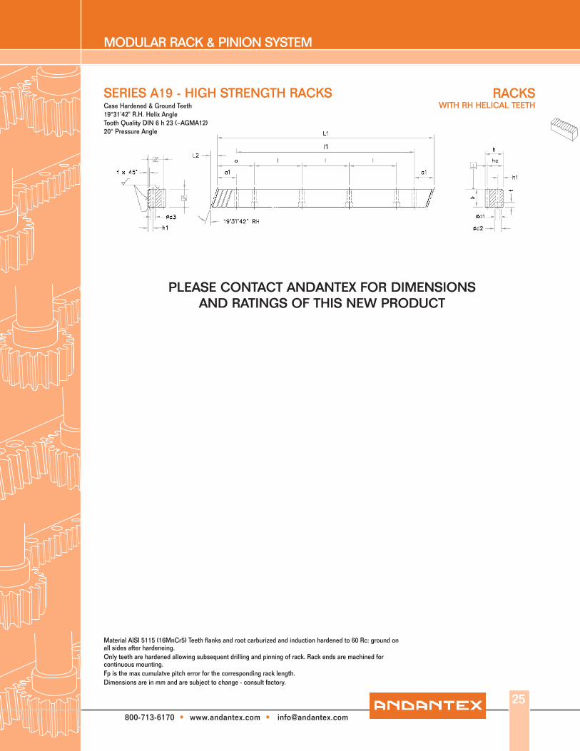
Material AISI 5115 (16MnCr5) Teeth flanks and root carburized and induction hardened to 60 Rc: ground on all sides after hardeneing.Only teeth are hardened allowing subsequent drilling and pinning of rack. Rack ends are machined for continuous mounting.Fp is the max cumulatve pitch error for the corresponding rack length.Dimensions are in mm and are subject to change - consult factory.
SERIES A19 - HIGH STRENGTH RACKSCase Hardened & Ground Teeth 19°31'42" R.H. Helix Angle Tooth Quality DIN 6 h 23 (~AGMA12) 20° Pressure Angle
No. mass
25
RACKS WITH RH HELICAL TEETH
PLEASE CONTACT ANDANTEX FOR DIMENSIONS AND RATINGS OF THIS NEW PRODUCT

MODULAR RACK & PINION SYSTEM
800-713-6170 • www.andantex.com • [email protected]
SERIES A21
Module L1 L2 teeth b h ho f l1 a lNo.
holes h1 d1 d2 t a1 d3 Fp mass kg. Part no.
2.0 500 8.5 75 24 24 22 2 436.6 62.5 125 4 8 7 11 7 31.7 5.7 2.1 A21-020-0502.0 500 8.5 75 24 24 22 2 without holes 2.1 A21-021-0502.0 1000 8.5 150 24 24 22 2 936.6 62.5 125 8 8 7 11 7 31.7 5.7 0.063 4.2 A21-020-1002.0 1000 8.5 150 24 24 22 2 without holes 0.063 4.2 A21-021-1002.0 2000 8.5 300 24 24 22 2 1936.6 62.5 125 16 8 7 11 7 31.7 5.7 8.6 A21-020-2002.0 2000 8.5 300 24 24 22 2 without holes 8.6 A21-021-2002.0 Companion Rack For Assembly A11-021-999-W
3.0 500 10.3 50 29 29 26 2 430 62.5 125 4 9 10 15 9 35 7.7 3 A21-030-0503.0 500 10.3 50 29 29 26 2 without holes 3 A21-031-0503.0 1000 10.3 100 29 29 26 2 930 62.5 125 8 9 10 15 9 35 7.7 0.071 6 A21-030-1003.0 1000 10.3 100 29 29 26 2 without holes 0.071 6 A21-031-1003.0 2000 10.3 200 29 29 26 2 1930 62.5 125 16 9 10 15 9 35 7.7 12.2 A21-030-2003.0 2000 10.3 200 29 29 26 2 without holes 12.2 A21-031-2003.0 Companion Rack for Assembly A11-031-999-W
4.0 506.67 13.8 38 39 39 35 2 433 62.5 125 4 12 10 15 9 33.3 7.7 5.5 A21-040-0504.0 506.67 13.8 38 39 39 35 2 without holes 5.5 A21-041-0504.0 1000 13.8 75 39 39 35 2 933.4 62.5 125 8 12 10 15 9 33.3 7.7 0.080 10.9 A21-040-1004.0 1000 13.8 75 39 39 35 2 without holes 0.080 10.9 A21-041-1004.0 2000 13.8 150 39 39 35 2 1933.4 62.5 125 16 12 10 15 9 33.3 7.7 21.8 A21-040-2004.0 2000 13.8 150 39 39 35 2 without holes 21.8 A21-041-2004.0 Companion Rack for Assembly A11-041-999-W
5.0 500 17.4 30 49 39 34 2 425 62.5 125 4 12 14 20 13 37.5 11.7 6.5 A21-050-0505.0 500 17.4 30 49 39 34 2 without holes 6.5 A21-051-0505.0 1000 17.4 60 49 39 34 2 925 62.5 125 8 12 14 20 13 37.5 11.7 0.080 13 A21-050-1005.0 1000 17.4 60 49 39 34 2 without holes 0.080 13 A21-051-1005.0 2000 17.4 120 49 39 34 2 1925 62.5 125 16 12 14 20 13 37.5 11.7 26 A21-050-2005.0 2000 17.4 120 49 39 34 2 without holes 26 A21-051-2005.0 Companion Rack for Assembly A11-051-999-W
Material AISI 4140 (42CrMo4V) with tensile strength = 900 N/mm2 (130,500 PSI). Back and contact faces ground. Rack ends are machined for continuous mounting.
Fp is the max cumulative pitch error for the corresponding rack length.
Dimensions are in mm and are subject to change - consult factory.
RACKSWITH RH HELICAL TEETH Quenched & Tempered Material
19°31'42" R.H. Helix Angle Tooth Quality DIN 8 h 27 (~AGMA10)
20° Pressure Angle
26

MODULAR RACK & PINION SYSTEM
800-713-6170 • www.andantex.com • [email protected]
Material AISI 1045 (C45) with tensile strength = 650 N/mm2 (95,000 PSI). Rack ends are machined for continuous mounting.
Fp is the max cumulatve pitch error for the corresponding rack length.
Dimensions are in mm and are subject to change - consult factory.
SERIES A31
Module L1 L2 teeth b h ho f l1 a l No. holes h1 d1 d2 t a1 d3 Fp mass
kg. Part no.
1.5 1000 6.0 200 17 16.80 15.30 1 936.6 62.5 125 8 6 6 10 6 31.7 5.7 0.090 2.0 A31-1.50-1001.5 1000 6.0 200 17 16.80 15.30 1 Without Holes 0.090 2.0 A31-1.51-1001.5 1500 6.0 300 17 16.80 15.30 1 1436.6 62.5 125 12 6 6 10 6 31.7 5.7 3.0 A31-1.50-1501.5 1500 6.0 300 17 16.80 15.30 1 Without Holes 3.0 A31-1.51-1501.5 2000 6.0 400 17 16.80 15.30 1 1936.6 62.5 125 16 6 6 10 6 31.7 5.7 4.0 A31-1.50-2001.5 2000 6.0 400 17 16.80 15.30 1 Without Holes 4.0 A31-1.51-2001.5 Companion Rack For Assembly A11-1.51-9992.0 500 8.9 75 25 24.75 22.75 2 436.6 62.5 125 4 8 7 11 7 31.7 5.7 2.2 A31-020-0502.0 500 8.9 75 25 24.75 22.75 2 Without Holes 2.2 A31-021-0502.0 1000 8.9 150 25 24.75 22.75 2 936.6 62.5 125 8 8 7 11 7 31.7 5.7 0.090 4.4 A31-020-1002.0 1000 8.9 150 25 24.75 22.75 2 Without Holes 0.090 4.4 A31-021-1002.0 1500 8.9 225 25 24.75 22.75 2 1436.6 62.5 125 12 8 7 11 7 31.7 5.7 6.6 A31-020-1502.0 1500 8.9 225 25 24.75 22.75 2 Without Holes 6.6 A31-021-1502.0 2000 8.9 300 25 24.75 22.75 2 1936.6 62.5 125 16 8 7 11 7 31.7 5.7 8.8 A31-020-2002.0 2000 8.9 300 25 24.75 22.75 2 Without Holes 8.8 A31-021-2002.0 Companion Rack For Assembly A11-021-999-W3.0 500 10.6 50 30 29.75 26.75 2 430 62.5 125 4 9 10 15 9 35 7.7 3.1 A31-030-0503.0 500 10.6 50 30 29.75 26.75 2 Without Holes 3.1 A31-031-0503.0 1000 10.6 100 30 29.75 26.75 2 930 62.5 125 8 9 10 15 9 35 7.7 0.100 6.2 A31-030-1003.0 1000 10.6 100 30 29.75 26.75 2 Without Holes 0.100 6.2 A31-031-1003.0 2000 10.6 200 30 29.75 26.75 2 1930 62.5 125 16 9 10 15 9 35 7.7 12.5 A31-030-2003.0 2000 10.6 200 30 29.75 29.75 2 Without Holes 12.5 A31-031-2003.0 Companion Rack for Assembly A11-031-999-W4.0 506.67 14.2 38 40 39.7 35.7 3 433 62.5 125 4 12 10 15 9 33.3 7.7 5.6 A31-040-0504.0 506.67 14.2 38 40 39.7 35.7 3 Without Holes 5.6 A31-041-0504.0 1000 14.2 75 40 39.7 35.7 3 933.4 62.5 125 8 12 10 15 9 33.3 7.7 0.110 11.1 A31-040-1004.0 1000 14.2 75 40 39.7 35.7 3 Without Holes 0.110 11.1 A31-041-1004.0 2000 14.2 150 40 39.7 35.7 3 1933.4 62.5 125 16 12 10 15 9 33.3 7.7 22.2 A31-040-2004.0 2000 14.2 150 40 39.7 35.7 3 Without Holes 22.2 A31-041-2004.0 Companion Rack for Assembly A11-041-999-W5.0 1000 17.7 60 50 39.7 34.7 3 925 62.5 125 8 12 14 20 13 37.5 11.7 0.110 13.2 A31-050-1005.0 1000 17.7 60 50 39.7 34.7 3 Without Holes 0.110 13.2 A31-051-1005.0 2000 17.7 120 50 39.7 34.7 3 1925 62.5 125 16 12 14 20 13 37.5 11.7 26.5 A31-050-2005.0 2000 17.7 120 50 39.7 34.7 3 Without Holes 26.5 A31-051-2005.0 Companion Rack for Assembly A11-051-999-W6.0 1000 21.3 50 60 49.7 43.7 3 925 62.5 125 8 16 18 26 17 37.5 15.7 0.110 20.1 A31-060-1006.0 1000 21.3 50 60 49.7 43.7 3 Without Holes 0.110 20.1 A31-061-1006.0 2000 21.3 100 60 49.7 43.7 3 1925 62.5 125 16 16 18 26 17 37.5 15.7 40.2 A31-060-2006.0 2000 21.3 100 60 49.7 43.7 3 Without Holes 40.2 A31-061-2006.0 Companion Rack for Assembly A11-061-999-W8.0 960 28.4 36 80 79.6 71.6 3 720 60.0 120 8 25 25 33 21 120.0 19.7 0.110 44.8 A31-080-1008.0 960 28.4 36 80 79.6 71.6 3 Without Holes 0.110 44.8 A31-081-1008.0 1920 28.4 72 80 79.6 71.6 3 1680 60.0 120 16 25 25 33 21 120 19.7 89.7 A31-080-2008.0 1920 28.4 72 80 79.6 71.6 3 Without Holes 89.7 A31-081-2008.0 Companion Rack for Assembly A11-081-999-W10.0 1000 35.5 30 100 99 89 3 750 62.5 125 8 32 33 48 32 125 19.7 69.8 A31-100-10010.0 1000 35.5 30 100 99 89 3 Without Holes 69.8 A31-101-10010.0 Companion Rack for Assembly A11-101-999-W
RACKS WITH RH HELICAL TEETHSoft
19°31'42" R.H. Helix AngleTooth Quality DIN 9 h 27 (~AGMA 9) 20° Pressure Angle
27

MODULAR RACK & PINION SYSTEM
800-713-6170 • www.andantex.com • [email protected]
Material AISI 1045 (C45) with tensile strength = 650 N/mm2 (95,000 PSI). Teeth are induction hardened to 50-55Rc. Back and contact faces are machined after hardening. Only teeth are induction hardened allowing subsequent drilling and pinning of the rack. Rack ends are machined for continuous mounting.
Fp is the max cumulative pitch error for the corresponding rack length.
Dimensions are in mm and are subject to change - consult factory.
SERIES A41
28
Module L1 L2 teeth b h ho f l1 a lNo.
holes h1 d1 d2 t a1 d3 Fp mass kg. Part no.
2.0 500 8.5 75 24 24 22 2 436.6 62.5 125 4 8 7 11 7 31.7 5.7 2.1 A41-020-0502.0 500 8.5 75 24 24 22 2 without holes 2.1 A41-021-0502.0 1000 8.5 150 24 24 22 2 936.6 62.5 125 8 8 7 11 7 31.7 5.7 0.140 4.2 A41-020-1002.0 1000 8.5 150 24 24 22 2 without holes 0.140 4.2 A41-021-1002.0 2000 8.5 300 24 24 22 2 1936.6 62.5 125 16 8 7 11 7 31.7 5.7 8.4 A41-020-2002.0 2000 8.5 300 24 24 22 2 without holes 8.4 A41-021-2002.0 Companion Rack For Assembly A11-021-999-W
3.0 500 10.3 50 29 29 26 2 430 62.5 125 4 9 10 15 9 35 7.7 3 A41-030-0503.0 500 10.3 50 29 29 26 2 without holes 3 A41-031-0503.0 1000 10.3 100 29 29 26 2 930.6 62.5 125 8 9 10 15 9 35 7.7 0.160 6 A41-030-1003.0 1000 10.3 100 29 29 26 2 without holes 0.160 6 A41-031-1003.0 2000 10.3 200 29 29 26 2 1930.6 62.5 125 16 9 10 15 9 35 7.7 12 A41-030-2003.0 2000 10.3 200 29 29 26 2 without holes 12 A41-031-2003.0 Companion Rack for Assembly A11-031-999-W
4.0 506.67 13.8 38 39 39 35 3 433 62.5 125 4 12 10 15 9 33.3 7.7 5.3 A41-040-0504.0 506.67 13.8 38 39 39 35 3 without holes 5.3 A41-041-0504.0 1000 13.8 75 39 39 35 3 933.4 62.5 125 8 12 10 15 9 33.3 7.7 0.180 10.6 A41-040-1004.0 1000 13.8 75 39 39 35 3 without holes 0.180 10.6 A41-041-100
4.0 2000 13.8 150 39 39 35 3 1933.4 62.5 125 16 12 10 15 9 33.3 7.7 21.2 A41-040-200
4.0 2000 13.8 150 39 39 35 3 without holes 21.2 A41-041-2004.0 Companion Rack for Assembly A11-041-999-W
5.0 500 17.4 30 49 39 34 3 425 62.5 125 4 12 14 20 13 37.5 11.7 6.5 A41-050-0505.0 500 17.4 30 49 39 34 3 without holes 6.5 A41-051-0505.0 1000 17.4 60 49 39 34 3 925 62.5 125 8 12 14 20 13 37.5 11.7 0.180 13 A41-050-1005.0 1000 17.4 60 49 39 34 3 without holes 0.180 13 A41-051-1005.0 Companion Rack for Assembly A11-051-999-W
6.0 500 20.9 25 59 49 43 3 425 62.5 125 4 16 18 26 17 37.5 15.7 9.9 A41-060-0506.0 500 20.9 25 59 49 43 3 without holes 9.9 A41-061-0506.0 1000 20.9 50 59 49 43 3 925 62.5 125 8 16 18 26 17 37.5 15.7 0.180 19.8 A41-060-1006.0 1000 20.9 50 59 49 43 3 without holes 0.180 19.8 A41-061-1006.0 Companion Rack for Assembly A11-061-999-W
Induction Hardened Teeth19°31'42" R.H. Helix Angle
Quality DIN 10 h 27 (~AGMA 8) 20° Pressure Angle
RACKSWITH RH HELICAL TEETH
MODULAR RACK & PINION SYSTEM
800-713-6170 • www.andantex.com • [email protected]
29
RACKS MACHINED FOR LINEAR GUIDEWAYS
Series Style Module Heat Treatment Quality Level* Page
A52 __ _ __Straight (spur)
for rail 180°5,10
circular pitch, pHardened & Ground
6 h 23(~AGMA 12)
30
A54 __ _ __Straight (spur)
for rail 90°5,10
circular pitch, pHardened & Ground
6 h 23(~AGMA 12)
30
A72 __ _ __Straight (spur)
for rail 180°5,10
circular pitch, pSoft
9 h 27(~AGMA 9)
31
A74 __ _ __Straight (spur)
for rail 90°5,10
circular pitch, pSoft
9 h 27(~AGMA 9)
31
A15 __ _ __Helical for Rail
180°2, 3, 4 Hardened & Ground
6 h 23(~AGMA 12)
32
A17 __ _ __Helical for Rail
90°2, 3, 4 Hardened & Ground
6 h 23(~AGMA 12)
32
A33 __ _ __Helical for Rail
180°2, 3, 4 Soft
9 h 27(~AGMA 9)
33
A35 __ _ __Helical for Rail
90°2, 3, 4 Soft
9 h 27(~AGMA 9)
33
RACK, RAIL & BEARING BLOCK ASSEMBLY
Series Style Module Heat Treatment Quality Level* Page
Z2 __ _ __RZ4 __ _ __R
Straight (spur)for rail 180°
5,10circular pitch, p
Hardened & Ground or Soft
6 h 23 (~AGMA 12)9 h 27 (~AGMA 9)
34
Z2 __ _ __ZZ4 __ _ __Z
Straight (spur)for rail 90°
5,10circular pitch, p
Hardened & Ground or Soft
6 h 23 (~AGMA 12)9 h 27 (~AGMA 9)
35
Z1 __ _ __RZ3 __ _ __R
Helical with rail 180°
2, 3, 4Hardened & Ground
or Soft6 h 23 (~AGMA 12)9 h 27 (~AGMA 9)
36
Z1 __ _ __ZZ3 __ _ __Z
Helical with rail 90°
2, 3, 4Hardened & Ground
or Soft6 h 23 (~AGMA 12)9 h 27 (~AGMA 9)
37
180° RACK GUIDEWAY DESIGN
90° RACK GUIDEWAY DESIGN
*Note all AGMA quality grades in this catalog are based on AGMA standard 2000-A88. The new AGMA quality numbers defined in AGMA 2015-1-A01 are similar to the DIN numbers shown.

MODULAR RACK & PINION SYSTEM
800-713-6170 • www.andantex.com • [email protected]
RACKSWITH CIRCULAR PITCH STRAIGHT (SPUR) TEETH MACHINED FOR LINEAR RAILS MOUNTED 90° FROM TOOTH SIDE
Material AISI 1045 (C45) with tensile strength = 650 N/mm2 (95,000 PSI). Teeth induction hardened to 50-55 Rc; ground on all sides after hardening. Only teeth are hardened allowing subsequent drilling and pinning of rack. Rack ends are machined for continuous mounting.
Fp is the max cumulative pitch error for the corresponding rack length.
Dimensions are in mm and are subject to change - consult factory.
Case Hardened & Ground TeethTooth Quality DIN 6 h 23 (~AGMA12)
20° Pressure Angle
SERIES A54
RACKS WITH CIRCULAR PITCH STRAIGHT (SPUR) TEETH MACHINED FOR LINEAR RAILS MOUNTED 180° FROM TOOTH SIDE
SERIES A52Case Hardened & Ground Teeth
Tooth Quality DIN 6 h 23 (~AGMA12) 20° Pressure Angle
Material AISI 1045 (C45) with tensile strength = 650 N/mm2 (95,000 PSI). Teeth induction hardened to 50-55 Rc; ground on all sides after hardeneing. Only teeth are hardened allowing subsequent drilling and pinning of rack. Rack ends are machined for continuous mounting.Fp is the max cumulative pitch error for the corresponding rack length.
Dimensions are in mm and are subject to change - consult factory.
Circular Pitch, p Module L1 teeth b h ho f a l holes h1 d1 d2 t a1 m3 h3 t3 Fp kg. Part no.
5.0 1.591 960 192 19 19.50 17.9 1 10 60 16 7.5 5.8 10 6 30 M4 7.5 8.0 0.032 2.7 A52-050-1005.0 1.591 960 192 24 24.50 22.91 1 10 60 16 10.0 7.0 11 7 30 M5 10.0 11.0 0.032 4.2 A52-050-100-245.0 1.591 Companion Rack for Assembly A52-051-999
10.0 3.183 960 96 29 29.75 26.57 2 10 60 16 11.5 10.0 15 9 30 M6 11.5 13.5 0.038 5.6 A52-100-10010.0 3.183 Companion Rack for Assembly A52-101-999
Circular Pitch, p Module L1 teeth b h ho f a l holes h1 d1 d2 t a1 d3 Fp kg. Part no.
5.0 1.591 960 192 19 19.50 17.91 1 10 60 16 7.5 4.5 7.5 5.3 30 4.5 2.7 A54-050-1005.0 1.591 960 192 24 24.50 22.91 1 10 60 16 10.0 6.0 9.5 8.5 30 6.0 4.2 A54-050-100-245.0 1.591 Companion Rack for Assembly A52-051-999
10.0 3.183 960 96 29 29.75 26.57 2 10 60 16 11.5 7.0 11.0 9.0 30 7.0 5.6 A54-100-10010.0 3.183 Companion Rack for Assembly A52-101-999
b
h1
t3
m3
h3
a
a1
l l l l l l l
l l l l l l l
t
1x45°
fx45° d2
h
d1
L1
ho
b
h1
a
a1
l l l l l l l
l l l l l l l
t
1x45°
fx45° d2
h
d1
L1
d3
h
ho
30
MODULAR RACK & PINION SYSTEM
800-713-6170 • www.andantex.com • [email protected]
RACKSWITH CIRCULAR PITCH STRAIGHT (SPUR) TEETH
MACHINED FOR LINEAR RAILS MOUNTED 180° FROM TOOTH SIDE
RACKSWITH CIRCULAR PITCH STRAIGHT (SPUR) TEETH
MACHINED FOR LINEAR RAILS MOUNTED 90° FROM TOOTH SIDE
Soft TeethTooth Quality DIN 9 h 27 (~AGMA 9)20° Pressure Angle
Soft TeethTooth Quality DIN 9 h 27 (~AGMA 9)20° Pressure Angle
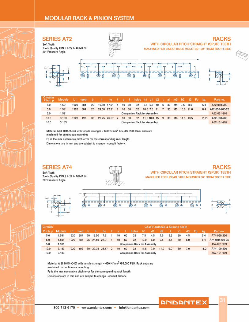
SERIES A72
SERIES A74
Material AISI 1045 (C45) with tensile strength = 650 N/mm2 (95,000 PSI). Rack ends are machined for continuous mounting. Fp is the max cumulative pitch error for the corresponding rack length.
Dimensions are in mm and are subject to change - consult factory.
Material AISI 1045 (C45) with tensile strength = 650 N/mm2 (95,000 PSI). Rack ends are machined for continuous mounting. Fp is the max cumulative pitch error for the corresponding rack length.
Dimensions are in mm and are subject to change - consult factory.
Circular Pitch, p Module L1 teeth b h ho f a l holes h1 d1 d2 t a1 m3 h3 t3 Fp kg. Part no.
5.0 1.591 1920 384 20 19.50 17.91 1 10 60 32 7.5 5.8 10 6 30 M4 7.5 8.0 5.4 A72-050-2005.0 1.591 1920 384 25 24.50 22.91 1 10 60 32 10.0 7.0 11 7 30 M5 10.0 11.0 8.4 A72-050-200-255.0 1.591 Companion Rack for Assembly A52-051-999
10.0 3.183 1920 192 30 29.75 26.57 2 10 60 32 11.5 10.0 15 9 30 M6 11.5 13.5 11.2 A72-100-20010.0 3.183 Companion Rack for Assembly A52-101-999
Circular Case Hardened & Ground TeethPitch, p Module L1 teeth b h ho f a l holes h1 d1 d2 t a1 d3 Fp kg. Part no.
5.0 1.591 1920 384 20 19.50 17.91 1 10 60 32 7.5 4.5 7.5 5.3 30 4.5 5.4 A74-050-2005.0 1.591 1920 384 25 24.50 22.91 1 10 60 32 10.0 6.0 9.5 8.5 30 6.0 8.4 A74-050-200-255.0 1.591 Companion Rack for Assembly A52-051-999
10.0 3.183 1920 192 30 29.75 26.57 2 10 60 32 11.5 7.0 11.0 9.0 30 7.0 11.2 A74-100-20010.0 3.183 Companion Rack for Assembly A52-101-999
bh1
t3
m3
h3
a
a1
l l l l l l l
l l l l l l l
t
1x45°
fx45° d2
h
d1
L1
ho
b
h1
a
a1
l l l l l l l
l l l l l l l
t
1x45°
fx45° d2
h
d1
L1
d3
h
ho
31

MODULAR RACK & PINION SYSTEM
800-713-6170 • www.andantex.com • [email protected]
RACKS WITH RH HELICAL TEETH MACHINED FOR LINEAR RAILS MOUNTED 90° FROM TOOTH SIDE
Material AISI 1045 (C45) with tensile strength = 650 N/mm2 (95,000 PSI). Teeth induction hardened to 50-55 Rc; ground on all sides after hardening. Only teeth are hardened allowing subsequent drilling and pinning of rack. Rack ends are machined for continuous mounting.
Fp is the max cumulative pitch error for the corresponding rack length. Dimensions are in mm and are subject to change - consult factory.
Case Hardened & Ground Teeth19°31'42" R.H. Helix Angle
Tooth Quality DIN 6 h 23 (~AGMA12) 20° Pressure Angle
SERIES A17
SERIES A15
Material AISI 1045 (C45) with tensile strength = 650 N/mm2 (95,000 PSI). Teeth induction hardened to 50-55 Rc; ground on all sides after hardening. Only teeth are hardened allowing subsequent drilling and pinning of rack. Rack ends are machined for continuous mounting.Fp is the max cumulative pitch error for the corresponding rack length. Dimensions are in mm and are subject to change - consult factory.
Module L1 L2 teeth b h ho f a l holes h1 d1 d2 t a1 d3 Fp kg. Part no.
2.0 480 6.70 72 19 19.50 17.50 1 10 60 8 7.5 4.5 7.5 5.3 30 4.5 1.3 A17-020-0502.0 960 6.70 144 19 19.50 17.50 1 10 60 16 7.5 4.5 7.5 5.3 30 4.5 0.036 2.7 A17-020-1002.0 480 8.50 72 24 24.50 22.50 1 10 60 8 10.0 6.0 9.5 8.5 30 6.0 2.1 A17-020-050-242.0 960 8.50 144 24 24.50 22.50 1 10 60 16 10.0 6.0 9.5 8.5 30 6.0 0.036 4.2 A17-020-100-242.0 Companion Rack for Assembly A11-021-999-W
3.0 480 10.30 48 29 29.75 26.75 2 10 60 8 11.5 7.0 11.0 9.0 30 7.0 2.8 A17-030-0503.0 960 10.30 96 29 29.75 26.75 2 10 60 16 11.5 7.0 11.0 9.0 30 7.0 0.036 5.6 A17-030-1003.0 Companion Rack for Assembly A11-031-999-W
4.0 480 13.83 36 39 39.75 35.75 2 20 80 6 14.0 10.0 15.0 9.0 40 10.0 5.2 A17-040-0504.0 960 13.83 72 39 39.75 35.75 2 20 80 12 14.0 10.0 15.0 9.0 40 10.0 0.040 10.5 A17-040-1004.0 480 13.83 36 39 48.75 44.75 2 20 80 6 17.0 10.0 15.0 9.0 40 10.0 6.5 A17-040-050-14.0 960 13.83 72 39 48.75 44.75 2 20 80 12 17.0 10.0 15.0 9.0 40 10.0 0.040 13 A17-040-100-14.0 840 17.38 63 49 58.00 54.00 2 30 105 8 22.5 14.0 20.0 13.0 60 14.0 17.3 A17-040-100-494.0 Companion Rack for Assembly A11-041-999-W
a1
l
l
l
l
l
l
L1
b
h
d2
h1
1x45
°
d1
t
t3
m3
h3
fx45° hoa
L2
a1
l
l
l
l
l
l
L1
b
h
d2
h1
1x45
°
d1
t
h1d3
fx45° hoa
L2
RACKS WITH RH HELICAL TEETH MACHINED FOR LINEAR RAILS MOUNTED 180° FROM TOOTH SIDE
Module L1 L2 teeth b h ho f a l holes h1 d1 d2 t a1 m3 h3 t3 Fp mass kg. Part no.
2.0 960 6.70 144 19 19.50 17.50 1 10 60 16 7.5 5.8 10.0 6 30 M4 7.5 8.0 0.036 2.7 A15-020-1002.0 960 8.50 144 24 24.50 22.50 1 10 60 16 10.0 7.0 11.0 7 30 M5 10.0 11.0 0.036 4.2 A15-020-100-242.0 Companion Rack for Assembly A11-021-999-W
3.0 960 10.30 96 29 29.75 26.75 2 10 60 16 11.5 10 15.0 9 30 M6 11.5 13.5 0.036 5.6 A15-030-1003.0 Companion Rack for Assembly A11-031-999-W
4.0 960 13.83 72 39 39.75 35.75 2 20 80 12 14.0 12.0 18.0 12 40 M8 14.0 16.0 0.040 10.5 A15-040-1004.0 960 13.83 72 39 48.75 44.75 2 20 80 12 17.0 12.0 18.0 12 40 M8 17.0 16.0 0.040 13 A15-040-100-14.0 840 17.38 63 49 58.00 54.00 2 30 105 8 22.5 14.0 20.0 13 60 M12 22.5 25.0 0.040 17.3 A15-040-100-494.0 Companion Rack for Assembly A11-041-999-W
Case Hardened & Ground Teeth19°31'42" R.H. Helix Angle
Tooth Quality DIN 6 h 23 (~AGMA12) 20° Pressure Angle
32
MODULAR RACK & PINION SYSTEM
800-713-6170 • www.andantex.com • [email protected]
RACKSWITH RH HELICAL TEETH
MACHINED FOR LINEAR RAILS MOUNTED 180° FROM TOOTH SIDE
RACKSWITH RH HELICAL TEETH
MACHINED FOR LINEAR RAILS MOUNTED 90° FROM TOOTH SIDE
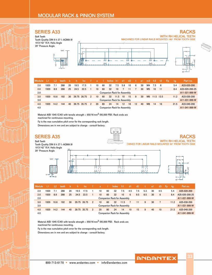
SERIES A33
SERIES A35
Material AISI 1045 (C45) with tensile strength = 650 N/mm2 (95,000 PSI). Rack ends are machined for continuous mounting. Fp is the max cumulative pitch error for the corresponding rack length.
Dimensions are in mm and are subject to change - consult factory.
Material AISI 1045 (C45) with tensile strength = 650 N/mm2 (95,000 PSI). Rack ends are machined for continuous mounting. Fp is the max cumulative pitch error for the corresponding rack length.
Dimensions are in mm and are subject to change - consult factory.
Module L1 L2 teeth b h ho f a l holes h1 d1 d2 t a1 m3 h3 t3 Fp kg. Part no.
2.0 1920 7.1 288 20 19.5 17.5 1 10 60 32 7.5 5.8 10 6 30 M4 7.5 8 5.4 A33-020-2002.0 1920 8.9 288 25 24.5 22.5 1 10 60 32 10 7 11 7 30 M5 10 11 8.4 A33-020-200-252.0 Companion Rack for Assembly A11-021-999-W
3.0 1920 10.6 192 30 29.75 26.75 2 10 60 32 11.5 10 15 9 30 M6 11.5 13.5 11.2 A33-030-2003.0 Companion Rack for Assembly A11-031-999-W
4.0 1920 14.2 144 40 39.75 35.75 2 20 80 24 14 12 18 12 40 M8 14 16 21.5 A33-040-2004.0 Companion Rack for Assembly A11-041-999-W
Module L1 L2 teeth b h ho f a l holes h1 d1 d2 t a1 d3 Fp kg. Part no.
2.0 1920 7.1 288 20 19.5 17.5 1 10 60 32 7.5 4.5 7.5 5.3 30 4.5 5.4 A35-020-2002.0 1920 8.9 288 25 24.5 22.5 1 10 60 32 10 6 9.5 8.5 30 6 8.4 A35-020-200-252.0 Companion Rack for Assembly A11-021-999-W
3.0 1920 10.6 192 30 29.75 26.75 2 10 60 32 11.5 7 11 9 30 7 11.2 A35-030-2003.0 Companion Rack for Assembly A11-031-999-W
4.0 1920 14.2 144 40 39.75 35.75 2 20 80 24 14 10 15 9 40 10 21.5 A35-040-2004.0 Companion Rack for Assembly A11-041-999-W
a1
l
l
l
l
l
l
L1
b
h
d2
h1
1x45
°
d1
t
t3
m3
h3
fx45° ho
L2
a
a1
l
l
l
l
l
l
L1
b
h
d2
h1
1x45
°
d1
t
h1d3
fx45° hoa
L2
Soft TeethTooth Quality DIN 9 h 27 (~AGMA 9)19˚31'42” R.H. Helix Angle20° Pressure Angle
Soft TeethTooth Quality DIN 9 h 27 (~AGMA 9)19˚31'42” R.H. Helix Angle20° Pressure Angle
33

MODULAR RACK & PINION SYSTEM
800-713-6170 • www.andantex.com • [email protected]
1) 1 = helical, ground, hardened (6h23)
2 = straight teeth, ground, hardened (6h23)
3 = helical, milled, soft (9h27)
4 = straight teeth, milled, soft (9h27)
2) design and dimensions of the blocks acc. to HG series
3) racks with great length are delivered in several parts. To bring them into the correct pitch
position, a mounting piece can be delivered.
4) maximum pitch error of the rack; rack length 300 mm.
34
Part no.toothingquality 1) design GT f/300 4) pitch L13) b hk h0 f a a1 rack
Z2HGR15R 2 180° 0.022 p = 5 960 19 19.50 17.91 1 10 30 A52-050-100Z4HGR15R 4 180° 0.059 p = 5 1920 20 19.50 17.91 1 10 30 A72-050-200Z2HGR20R 2 180° 0.022 p = 5 960 24 24.50 22.91 1 10 30 A52-050-100-24Z4HGR20R 4 180° 0.059 p = 5 1920 25 24.50 22.91 1 10 30 A72-050-200-25Z2HGR25R 2 180° 0.024 p = 10 960 29 29.75 26.57 2 10 30 A52-100-100Z4HGR25R 4 180° 0.065 p = 10 1920 30 29.75 26.57 2 10 30 A72-100-200
LINEAR GUIDEWAY WITH RACKZ SERIES
180° guideway with rack, straight teeth
180° version with rack, straight teeth
block type HGW.. 2)
block type HGH.. 2)
Part no. l h d1 d2 t BR WR NW HW NH HH
Z2HGR15R 60 7.5 5.8 10 6 34.50 15 16.0 43.50 9.5 47.50Z4HGR15R 60 7.5 5.8 10 6 34.50 15 16.0 43.50 9.5 47.50Z2HGR20R 60 10.0 7.0 11 7 42.00 20 21.5 54.50 12.0 54.50Z4HGR20R 60 10.0 7.0 11 7 42.00 20 21.5 54.50 12.0 54.50Z2HGR25R 60 11.5 10.0 15 9 51.75 23 23.5 65.75 12.5 69.75Z4HGR25R 60 11.5 10.0 15 9 51.75 23 23.5 65.75 12.5 69.75
For more detailed information, and the dimensions
of our racks for guideways, please see pages 26 - 27.

MODULAR RACK & PINION SYSTEM
800-713-6170 • www.andantex.com • [email protected]
1) 1 = helical, ground, hardened (6h23)
2 = straight teeth, ground, hardened (6h23)
3 = helical, milled, soft (9h27)
4 = straight teeth, milled, soft (9h27)
2) design and dimensions of the blocks acc. to HG series
3) racks with great length are delivered in several parts. To bring them into the correct pitch position, a mounting piece can be delivered.
4) maximum pitch error of the rack; rack length 300 mm.
Part no.toothingquality 1) design GT f/300 4) pitch L13) b hk h0 f a a1 rack
Z2HGR15Z 2 90° 0.022 p = 5 960 19 19.50 17.91 1 10 30 A54-050-100Z4HGR15Z 4 90° 0.059 p = 5 1920 20 19.50 17.91 1 10 30 A74-050-200Z2HGR20Z 2 90° 0.022 p = 5 960 24 24.50 22.91 1 10 30 A54-050-100-24Z4HGR20Z 4 90° 0.059 p = 5 1920 25 24.50 22.91 1 10 30 A74-050-200-25Z2HGR25Z 2 90° 0.024 p = 10 960 29 29.75 26.57 2 10 30 A54-100-100Z4HGR25Z 4 180° 0.065 p = 10 1920 30 29.75 26.57 2 10 30 A74-100-200
LINEAR GUIDEWAY WITH RACKZ SERIES
90° guideway with rack, straight teeth
90° version, straight teeth
block type HGW.. 2)block type HGH.. 2)
Part no. l h d1 d2 t BR WR NW HW NH HH
Z2HGR15Z 60 7.5 4.5 7.5 5.3 34.0 15 16.0 43 9.5 47Z4HGR15Z 60 7.5 4.5 7.5 5.3 35.0 15 16.0 44 9.5 48Z2HGR20Z 60 10.0 6.0 9.5 8.5 41.5 20 21.5 54 12.0 54Z4HGR20Z 60 10.0 6.0 9.5 8.5 42.5 20 21.5 55 12.0 55Z2HGR25Z 60 11.5 7.0 11.0 9.0 51.0 23 23.5 65 12.5 69Z4HGR25Z 60 11.5 7.0 11.0 9.0 52.0 23 23.5 66 12.5 70
For more detailed information, and the dimensions
of our racks for guideways, please see pages 26 - 27.
35

MODULAR RACK & PINION SYSTEM
800-713-6170 • www.andantex.com • [email protected]
1) 1 = helical, ground, hardened (6h23) 2 = straight teeth, ground, hardened (6h23) 3 = helical, milled, soft (9h27) 4 = straight teeth, milled, soft (9h27)2) design and dimensions of the blocks acc. to HG series3) racks with great length are delivered in several parts. To bring them into the correct pitch position, a mounting piece can be delivered.4) maximum pitch error of the rack; rack length 300 mm.36
Part no.toothingquality 1) design GT f/300 4) module L13) L2 b hk h0 f a rack
Z1HGR15R 1 180° 0.022 2 960 6.7 19 19.50 17.50 1 10 A15-020-100
Z3HGR15R 3 180° 0.061 2 1920 7.1 20 19.50 17.50 1 10 A33-020-200Z1HGR20R 1 180° 0.022 2 960 8.5 24 24.50 22.50 1 10 A15-020-100-24Z3HGR20R 3 180° 0.061 2 1920 8.9 25 24.50 22.50 1 10 A33-020-200-25Z1HGR25R 1 180° 0.024 3 960 10.3 29 29.75 26.75 2 10 A15-030-100Z3HGR25R 3 180° 0.065 3 1920 10.6 30 29.75 26.75 2 10 A33-030-200Z1HGR30R 1 180° 0.025 4 960 13.8 39 39.75 35.75 2 20 A15-040-100Z3HGR30R 3 180° 0.068 4 1920 14.2 40 39.75 35.75 2 20 A33-040-200Z1HGR35R 1 180° 0.025 4 960 13.8 39 48.75 44.75 2 20 A17-040-100-1Z1HGR45R 1 180° 0.025 4 840 17.4 49 58.00 54.00 2 30 A17-040-100-49
LINEAR GUIDEWAY WITH RACKZ SERIES
180° guideway with rack, helical
180° version, helical, right hand 19°31´42´´
block type HGW.. 2)
block type HGH.. 2)
Part no. a1 l h d1 d2 t BR WR NW HW NH HH
Z1HGR15R 30 60 7.5 5.8 10 6 34.50 15 16.0 43.50 9.5 47.50Z3HGR15R 30 60 7.5 5.8 10 6 34.50 15 16.0 43.50 9.5 47.50Z1HGR20R 30 60 10.0 7.0 11 7 42.00 20 21.5 54.50 12.0 54.50Z3HGR20R 30 60 10.0 7.0 11 7 42.00 20 21.5 54.50 12.0 54.50Z1HGR25R 30 60 11.5 10.0 15 9 51.75 23 23.5 65.75 12.5 69.75Z3HGR25R 30 60 11.5 10.0 15 9 51.75 23 23.5 65.75 12.5 69.75Z1HGR30R 40 80 14.0 12.0 18 12 65.75 28 31.0 81.75 16.0 84.75Z3HGR30R 40 80 14.0 12.0 18 12 65.75 28 31.0 81.75 16.0 84.75Z1HGR35R 40 80 17.0 12.0 18 12 77.75 34 33.0 96.75 18.0 103.75Z1HGR45R 60 105 22.5 14.0 20 13 96.00 45 37.5 118.00 20.5 128.00
For more detailed information, and the dimensions
of our racks for guideways, please see pages 28 - 29.
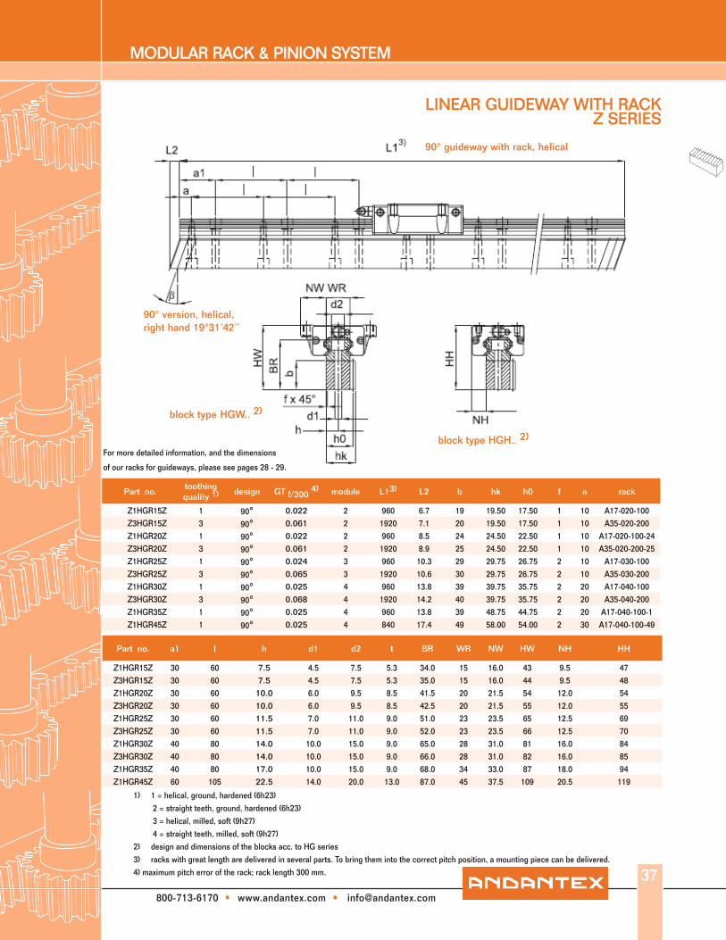
MODULAR RACK & PINION SYSTEM
800-713-6170 • www.andantex.com • [email protected]
1) 1 = helical, ground, hardened (6h23) 2 = straight teeth, ground, hardened (6h23) 3 = helical, milled, soft (9h27) 4 = straight teeth, milled, soft (9h27)2) design and dimensions of the blocks acc. to HG series3) racks with great length are delivered in several parts. To bring them into the correct pitch position, a mounting piece can be delivered.4) maximum pitch error of the rack; rack length 300 mm.
LINEAR GUIDEWAY WITH RACKZ SERIES
90° guideway with rack, helical
90° version, helical, right hand 19°31´42´´
block type HGW.. 2)
block type HGH.. 2)
37
Part no.toothingquality 1) design GT f/300 4) module L13) L2 b hk h0 f a rack
Z1HGR15Z 1 90° 0.022 2 960 6.7 19 19.50 17.50 1 10 A17-020-100Z3HGR15Z 3 90° 0.061 2 1920 7.1 20 19.50 17.50 1 10 A35-020-200Z1HGR20Z 1 90° 0.022 2 960 8.5 24 24.50 22.50 1 10 A17-020-100-24Z3HGR20Z 3 90° 0.061 2 1920 8.9 25 24.50 22.50 1 10 A35-020-200-25Z1HGR25Z 1 90° 0.024 3 960 10.3 29 29.75 26.75 2 10 A17-030-100Z3HGR25Z 3 90° 0.065 3 1920 10.6 30 29.75 26.75 2 10 A35-030-200Z1HGR30Z 1 90° 0.025 4 960 13.8 39 39.75 35.75 2 20 A17-040-100Z3HGR30Z 3 90° 0.068 4 1920 14.2 40 39.75 35.75 2 20 A35-040-200Z1HGR35Z 1 90° 0.025 4 960 13.8 39 48.75 44.75 2 20 A17-040-100-1Z1HGR45Z 1 90° 0.025 4 840 17.4 49 58.00 54.00 2 30 A17-040-100-49
Part no. a1 l h d1 d2 t BR WR NW HW NH HH
Z1HGR15Z 30 60 7.5 4.5 7.5 5.3 34.0 15 16.0 43 9.5 47Z3HGR15Z 30 60 7.5 4.5 7.5 5.3 35.0 15 16.0 44 9.5 48Z1HGR20Z 30 60 10.0 6.0 9.5 8.5 41.5 20 21.5 54 12.0 54Z3HGR20Z 30 60 10.0 6.0 9.5 8.5 42.5 20 21.5 55 12.0 55Z1HGR25Z 30 60 11.5 7.0 11.0 9.0 51.0 23 23.5 65 12.5 69Z3HGR25Z 30 60 11.5 7.0 11.0 9.0 52.0 23 23.5 66 12.5 70Z1HGR30Z 40 80 14.0 10.0 15.0 9.0 65.0 28 31.0 81 16.0 84Z3HGR30Z 40 80 14.0 10.0 15.0 9.0 66.0 28 31.0 82 16.0 85Z1HGR35Z 40 80 17.0 10.0 15.0 9.0 68.0 34 33.0 87 18.0 94Z1HGR45Z 60 105 22.5 14.0 20.0 13.0 87.0 45 37.5 109 20.5 119
For more detailed information, and the dimensions
of our racks for guideways, please see pages 28 - 29.