
MODULAR MOWER SHARPENING SYSTEM - Grinders, Rotary ... · MODULAR MOWER SHARPENING SYSTEM Patent...
58
MODEL 500 MODULAR MOWER SHARPENING SYSTEM Patent No. 5,321,912 Neary Technologies 1173 Benson Street River Falls, WI 54022 Manual No. 50300 (3-01) Please complete the following: Serial # Date Purchased Purchased From Phone #
Transcript of MODULAR MOWER SHARPENING SYSTEM - Grinders, Rotary ... · MODULAR MOWER SHARPENING SYSTEM Patent...

1
MODEL 500MODULAR MOWER
SHARPENING SYSTEMPatent No. 5,321,912
Neary Technologies1173 Benson StreetRiver Falls, WI 54022
Manual No. 50300 (3-01)
Please complete the following:
Serial #
Date Purchased
Purchased From
Phone #

2
Thank you for choosing Neary Technologies as your supplier of sharpening equipment. Neary Technologiesmachinery is for sharpening reel and rotary mower blades and bedknives. It is our goal to provide equipmentthat makes your job easier. Please read the manual for information regarding safety, set up and proper opera-tion of this equipment. In the future it may be necessary to order service parts for this machine. Please recordthe serial number and purchase information on this page as ready reference when ordering parts.
Warranty Registration , please complete the warranty registration included with this manual and return it tothe factory. We use these records to advise you of additional information about this machine as well as fortracking warranty information.
Model 500
The Model 500 is a modular design offered with several levels of features as well as different electrical volt-ages. This manual addresses the entire family of Models:
3
TABLE OF CONTENTS
ASSEMBLY .............................................................. Page 5 - 6
NEARY GRINDERS ................................................. Page 7 - 8
OPERATION ............................................................ Page 9 - 21
SET UP .................................................................... Page 22 - 24
MAINTENANCE & SERVICE ................................... Page 25 - 28
TROUBLE SHOOTING ........................................... Page 29 - 35
PARTS LISTS ........................................................ Page 36 - 58

4
Whenever operating equipment, the operator shouldalways use safe operating procedures. Throughout themanual you’ll see the Neary Technologies warning sign.These warning signs should be strictly adhered tobefore proceeding with the operations.
WARNING
5
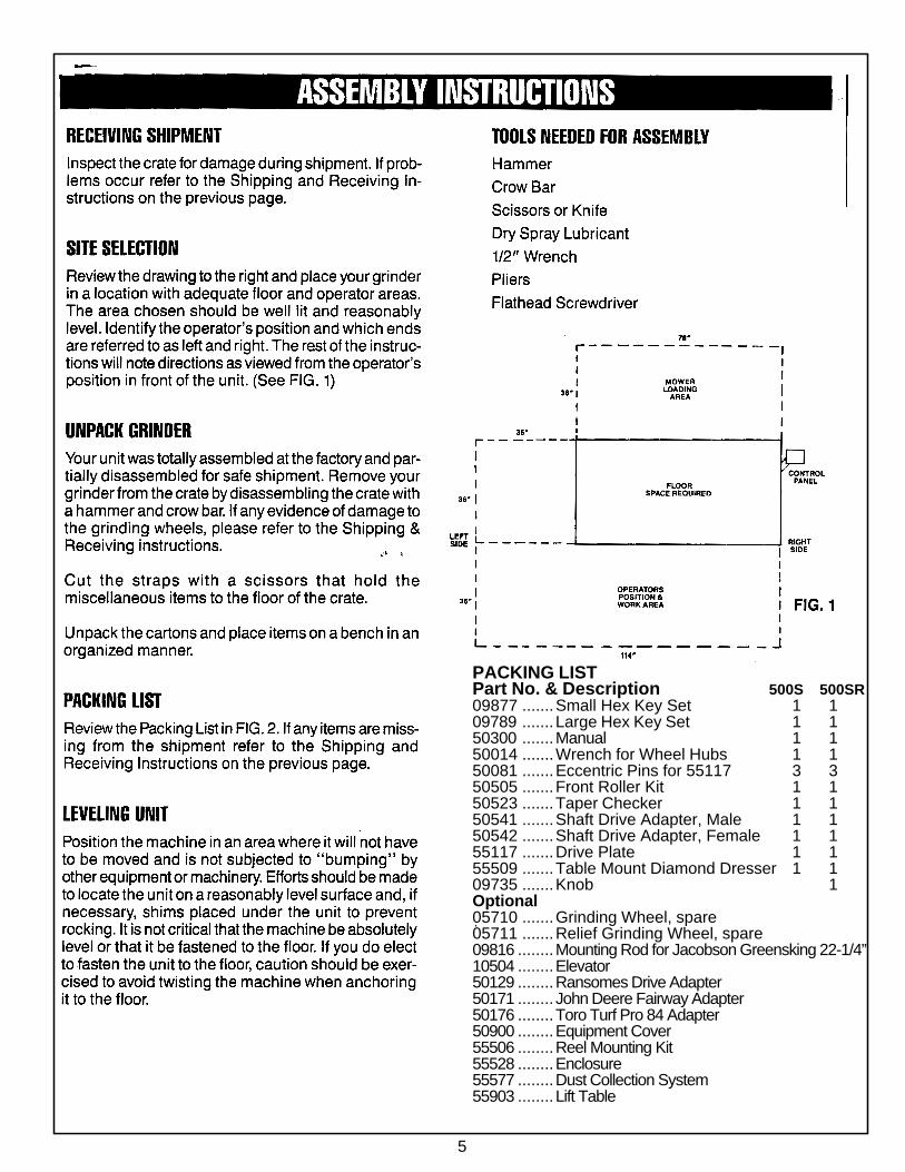
PACKING LISTPart No. & Description 500S 500SR09877 .......Small Hex Key Set 1 109789 .......Large Hex Key Set 1 150300 .......Manual 1 150014 .......Wrench for Wheel Hubs 1 150081 .......Eccentric Pins for 55117 3 350505 .......Front Roller Kit 1 150523 .......Taper Checker 1 150541 .......Shaft Drive Adapter, Male 1 150542 .......Shaft Drive Adapter, Female 1 155117 .......Drive Plate 1 155509 .......Table Mount Diamond Dresser 1 109735 .......Knob 1Optional05710 .......Grinding Wheel, spare05711 .......Relief Grinding Wheel, spare09816 ........Mounting Rod for Jacobson Greensking 22-1/4”10504 ........Elevator50129 ........Ransomes Drive Adapter50171 ........ John Deere Fairway Adapter50176 ........Toro Turf Pro 84 Adapter50900 ........Equipment Cover55506 ........Reel Mounting Kit55528 ........Enclosure55577 ........Dust Collection System55903 ........Lift Table
6
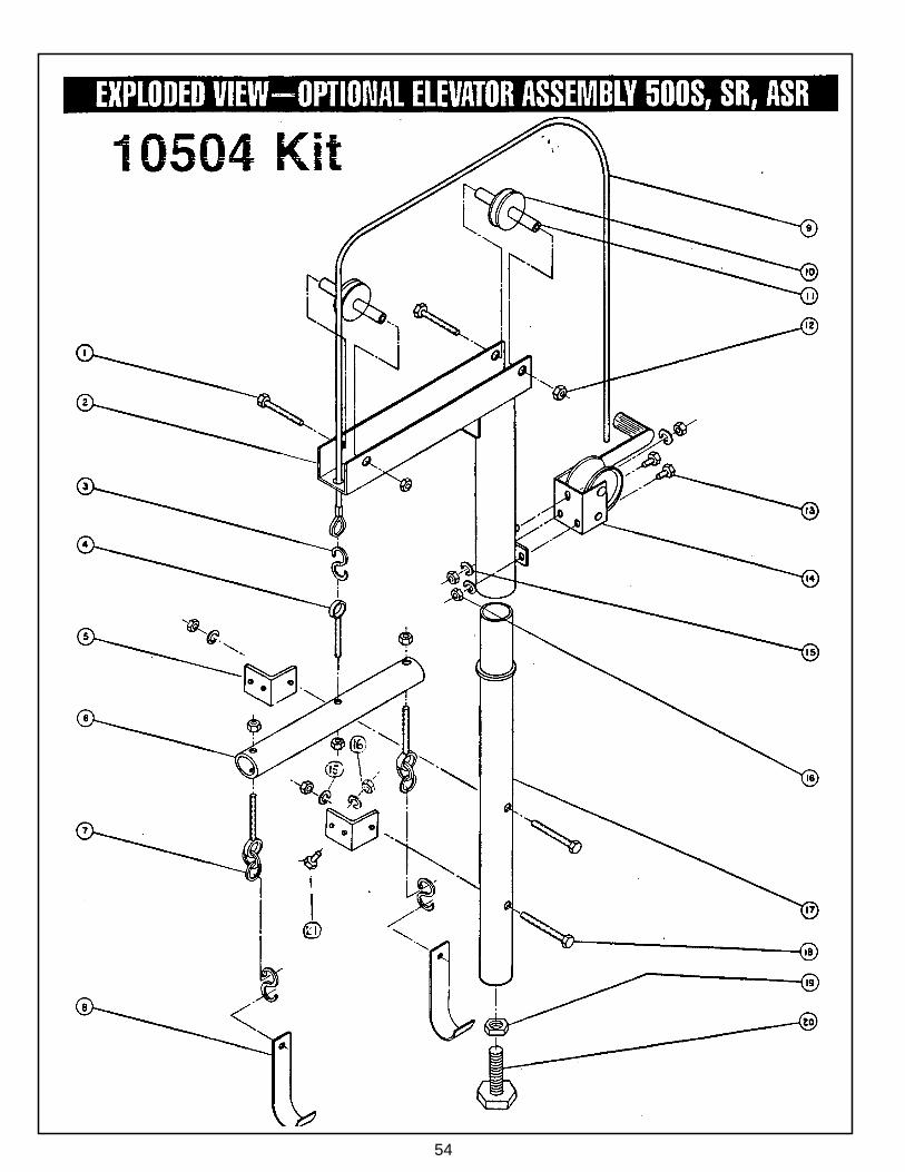
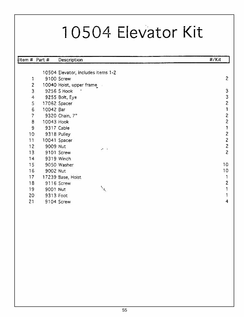
ASSEMBLY INSTRUCTIONSMOUNT OPTIONALELEVATOR WINCH ASSEMBLY -- #50104
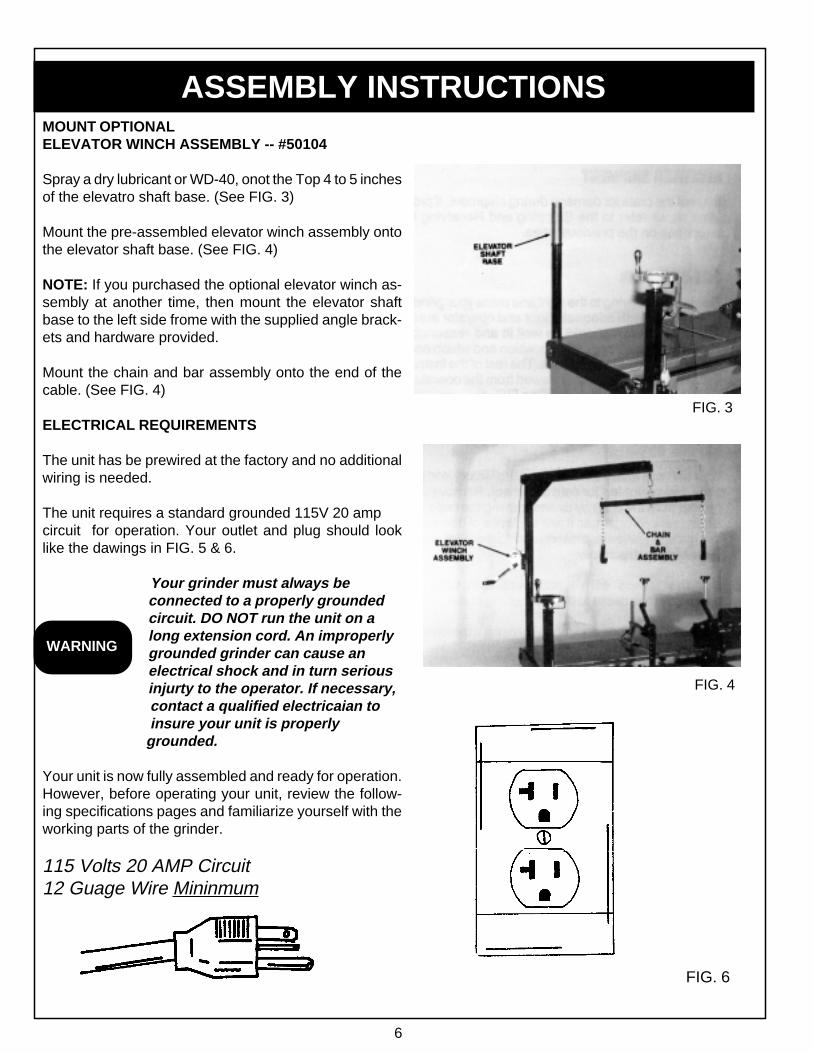
Spray a dry lubricant or WD-40, onot the Top 4 to 5 inchesof the elevatro shaft base. (See FIG. 3)
Mount the pre-assembled elevator winch assembly ontothe elevator shaft base. (See FIG. 4)
NOTE: If you purchased the optional elevator winch as-sembly at another time, then mount the elevator shaftbase to the left side frome with the supplied angle brack-ets and hardware provided.
Mount the chain and bar assembly onto the end of thecable. (See FIG. 4)
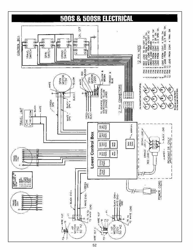
ELECTRICAL REQUIREMENTS
The unit has be prewired at the factory and no additionalwiring is needed.
The unit requires a standard grounded 115V 20 ampcircuit for operation. Your outlet and plug should looklike the dawings in FIG. 5 & 6.
Your grinder must always beconnected to a properly groundedcircuit. DO NOT run the unit on along extension cord. An improperlygrounded grinder can cause anelectrical shock and in turn seriousinjurty to the operator. If necessary,
contact a qualified electricaian to insure your unit is properly grounded.
Your unit is now fully assembled and ready for operation.However, before operating your unit, review the follow-ing specifications pages and familiarize yourself with theworking parts of the grinder.
115 Volts 20 AMP Circuit12 Guage Wire Mininmum
FIG. 6
FIG. 4
FIG. 3
WARNING
7
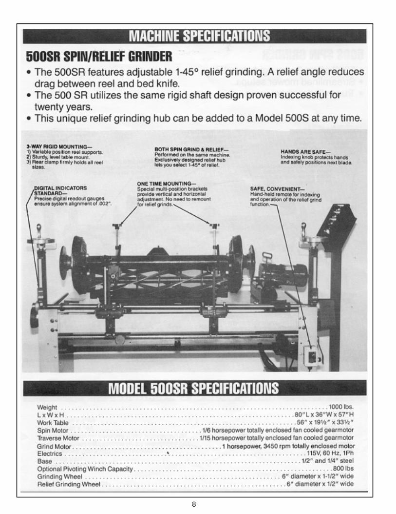
8
9
OPERATING SECTION
PLEASE READ THE FOLLOWINGINFORMATION ON THIS PAGE
BEFORE PROCEEDING ON WITHTHE OPERATING SECTION.
Because of the unique modular design of the 500 Series grinders, theoperating instructions of the 500 and 500SR are combined together on thefollowing pages. This may be a little confusing to follow at first, but as youupgrade from a 500S to 500SR, you will begin to appreciate why we havecombined instructions into one manual. You won’t have to start from scratchand learn “new” equipment in a “new” operating manual. You will just comeback to your basic set of instructions and build on what you already havelearned.
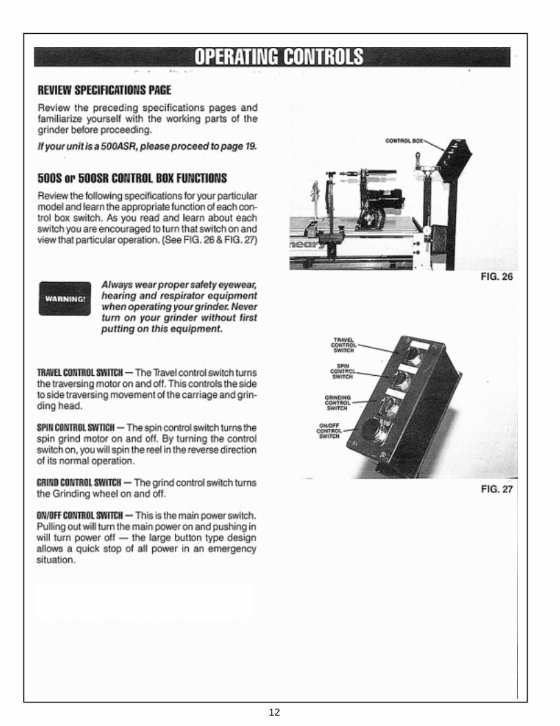
The most important part of this manual is the next five pages. Basic spinand relief grinding operations are very simple on Neary Technologies equip-ment. So the most important task at hand is to familiarize yourself with thecontrols and switches on your model of grinder. You are encouraged toturn on the controls and view its operation, and in no time you will begrinding with ease!
Service and training are very important to us at Neary Technologies. Pleasecall with questions or comments. Thanks for buying our equipment and welook forward to working with you in the years ahead.
10
11
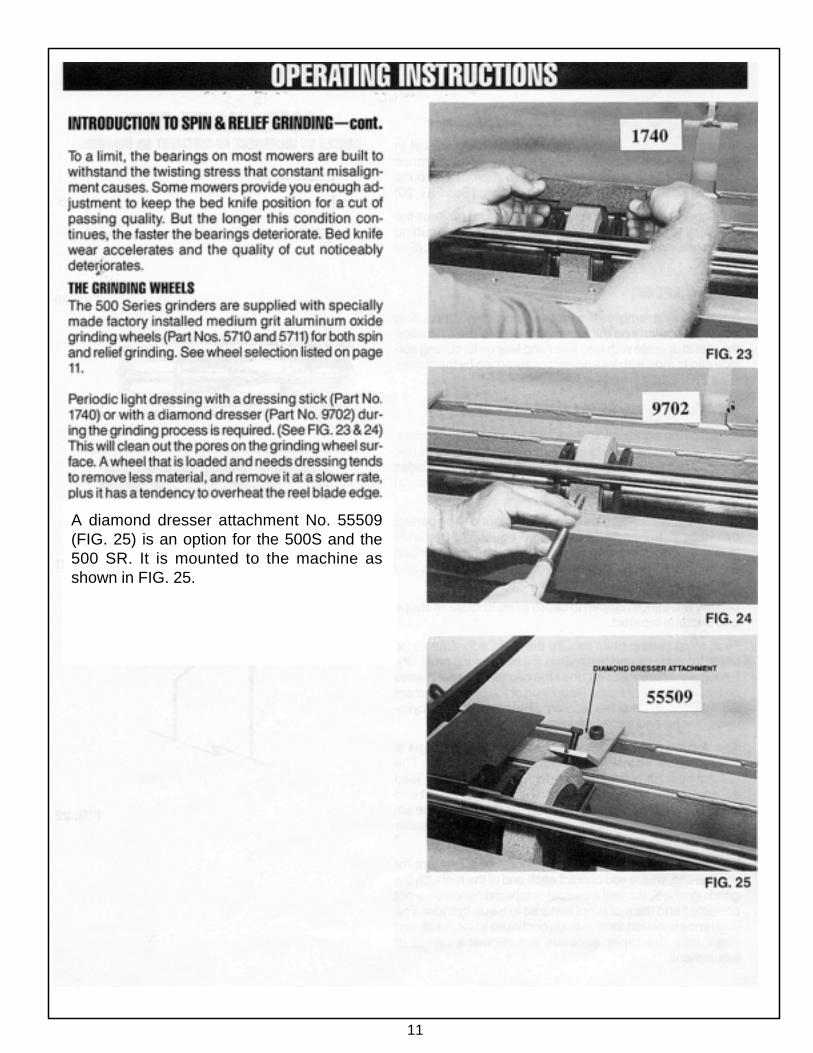
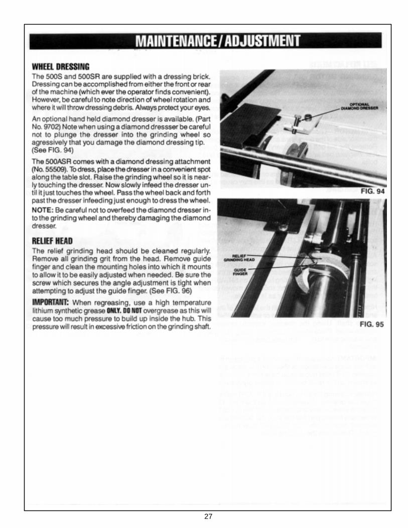
A diamond dresser attachment No. 55509(FIG. 25) is an option for the 500S and the500 SR. It is mounted to the machine asshown in FIG. 25.
12
13
14
15
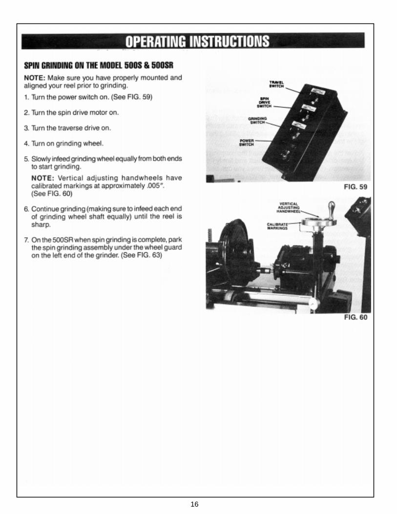
16
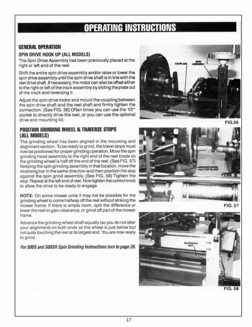
17
18
FIG. 48
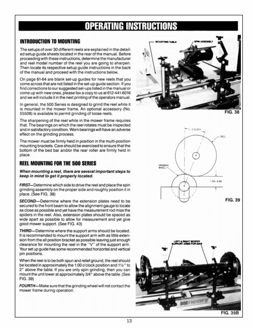
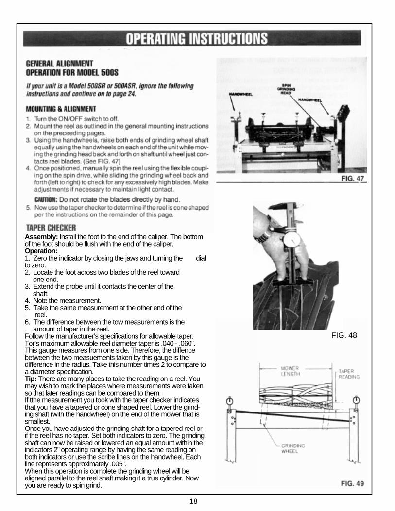
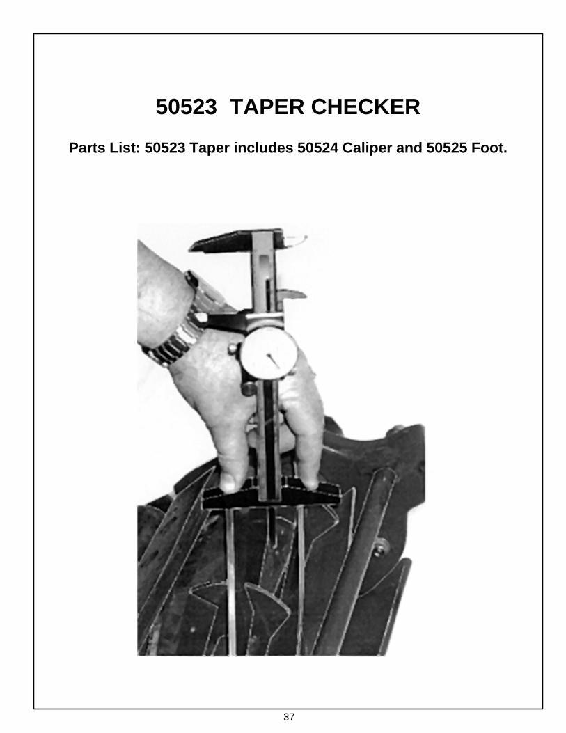
Assembly: Install the foot to the end of the caliper. The bottomof the foot should be flush with the end of the caliper.Operation:1. Zero the indicator by closing the jaws and turning the dialto zero.2. Locate the foot across two blades of the reel toward one end.3. Extend the probe until it contacts the center of the shaft.4. Note the measurement.5. Take the same measurement at the other end of the reel.6. The difference between the tow measurements is the amount of taper in the reel.Follow the manufacturer’s specifications for allowable taper.Tor’s maximum allowable reel diameter taper is .040 - .060”.This gauge measures from one side. Therefore, the diffencebetween the two measuements taken by this gauge is thedifference in the radius. Take this number times 2 to compare toa diameter specification.Tip: There are many places to take the reading on a reel. Youmay wish to mark the places where measurements were takenso that later readings can be compared to them.If tthe measurement you took with the taper checker indicatesthat you have a tapered or cone shaped reel. Lower the grind-ing shaft (with the handwheel) on the end of the mower that issmallest.Once you have adjusted the grinding shaft for a tapered reel orif the reel has no taper. Set both indicators to zero. The grindingshaft can now be raised or lowered an equal amount within theindicators 2” operating range by having the same reading onboth indicators or use the scribe lines on the handwheel. Eachline represents approximately .005”.When this operation is complete the grinding wheel will bealigned parallel to the reel shaft making it a true cylinder. Nowyou are ready to spin grind.
19
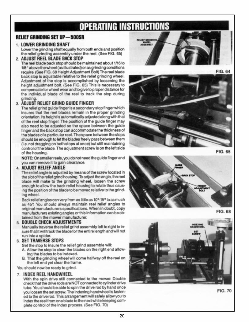
20

21
This page left intentionally blank for note taking purposes.
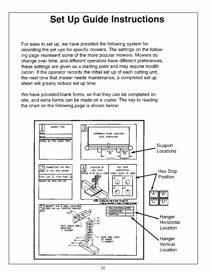
22

23
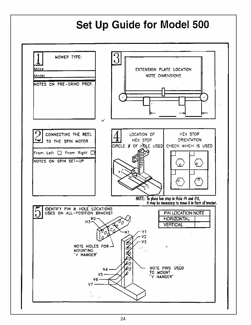
24
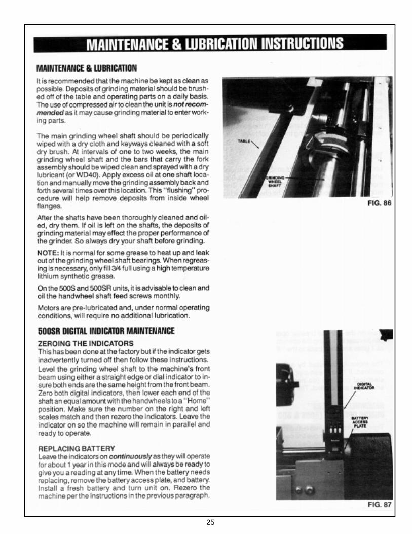
25
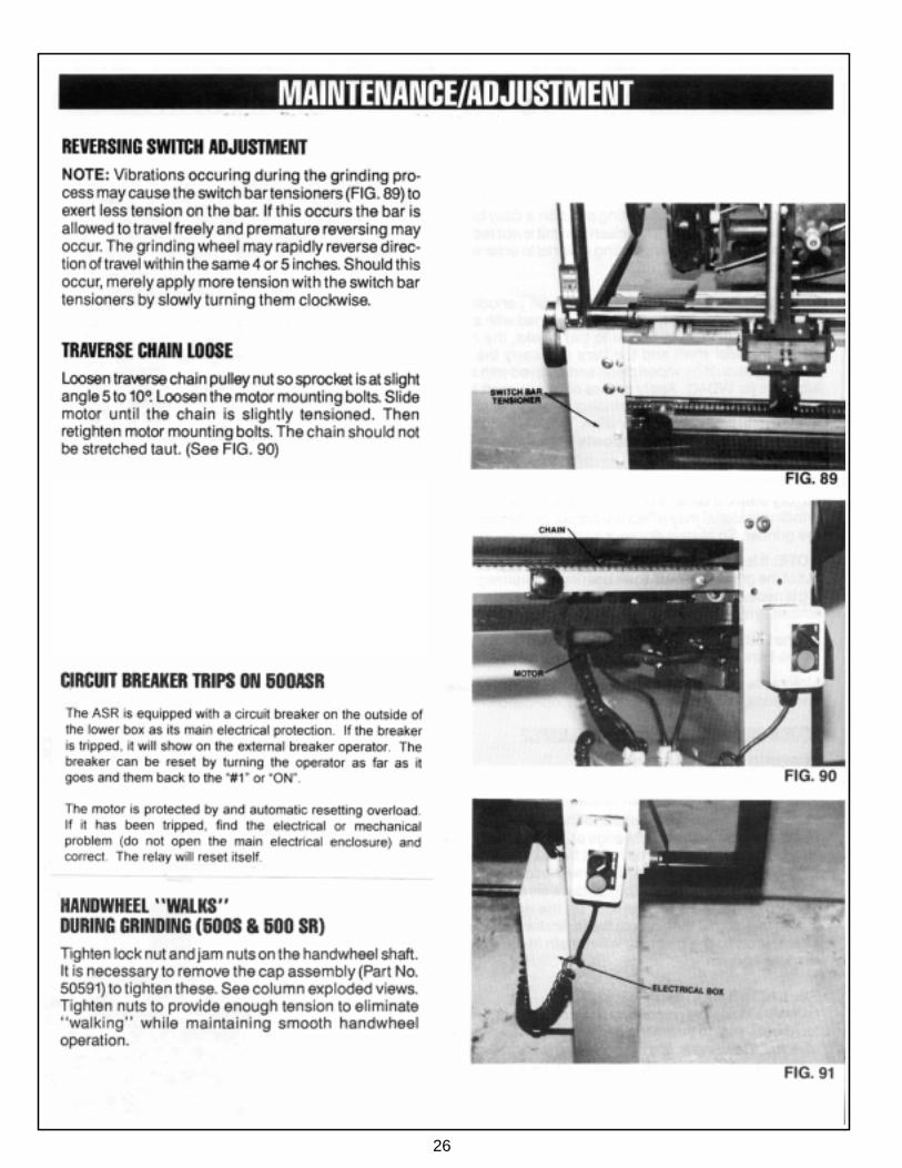
26
27
28
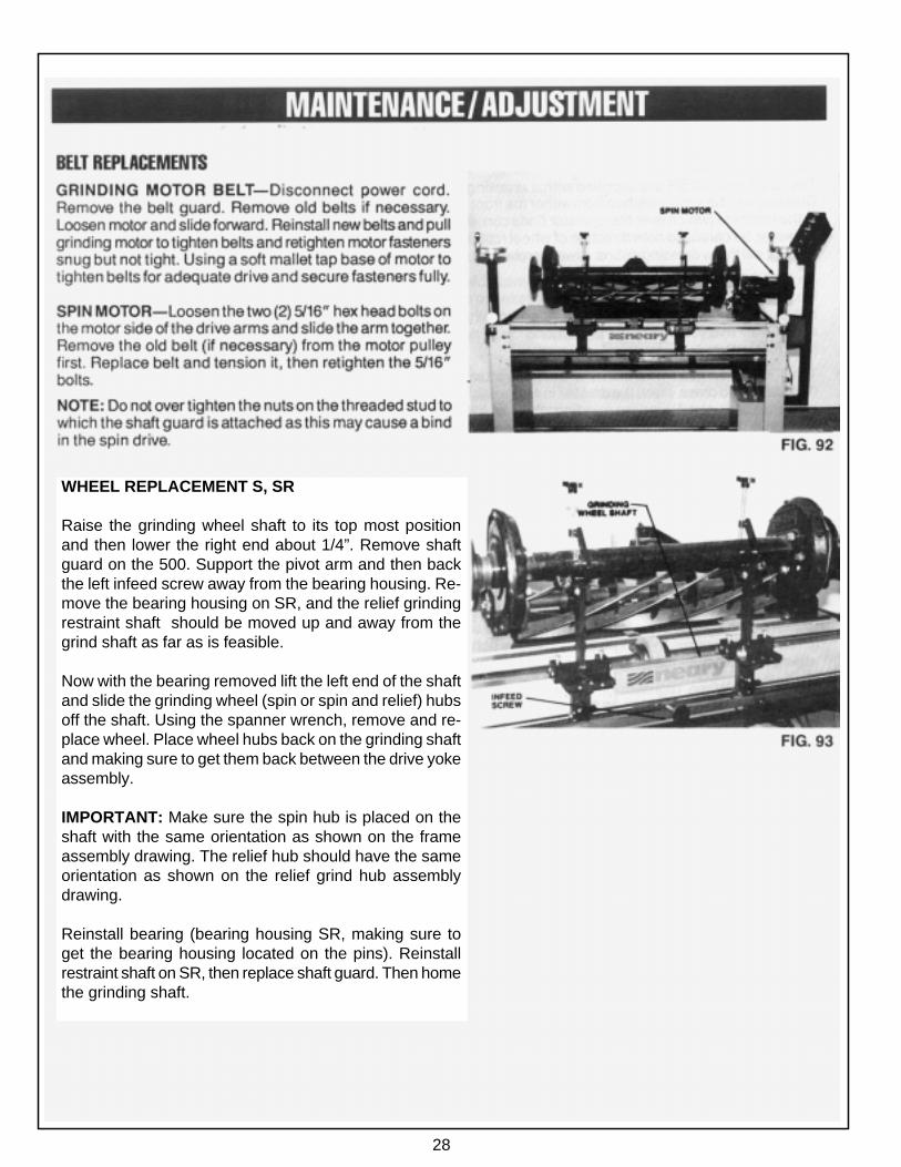
WHEEL REPLACEMENT S, SR
Raise the grinding wheel shaft to its top most positionand then lower the right end about 1/4”. Remove shaftguard on the 500. Support the pivot arm and then backthe left infeed screw away from the bearing housing. Re-move the bearing housing on SR, and the relief grindingrestraint shaft should be moved up and away from thegrind shaft as far as is feasible.
Now with the bearing removed lift the left end of the shaftand slide the grinding wheel (spin or spin and relief) hubsoff the shaft. Using the spanner wrench, remove and re-place wheel. Place wheel hubs back on the grinding shaftand making sure to get them back between the drive yokeassembly.
IMPORTANT: Make sure the spin hub is placed on theshaft with the same orientation as shown on the frameassembly drawing. The relief hub should have the sameorientation as shown on the relief grind hub assemblydrawing.
Reinstall bearing (bearing housing SR, making sure toget the bearing housing located on the pins). Reinstallrestraint shaft on SR, then replace shaft guard. Then homethe grinding shaft.

29

30

31

32

33
34
35

36
37
50523 TAPER CHECKER
Parts List: 50523 Taper includes 50524 Caliper and 50525 Foot.
38
39
40
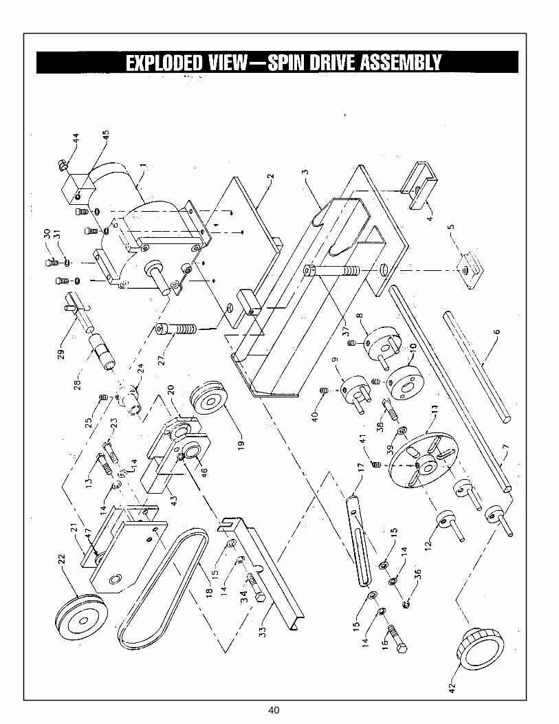
41
42
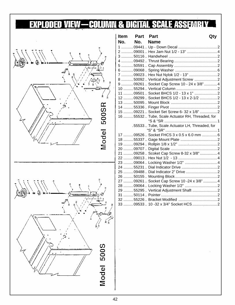
Item Part Part QtyNo. No. Name1 ........... 09441 .. Up - Down Decal ....................................22 ........... 09001 .. Hex Jam Nut 1/2 - 13” ............................43 ........... 50116 .. Handwheel .............................................24 ........... 09492 .. Thrust Bearing ........................................25 ........... 50591 .. Cap Assembly ........................................26 ........... 09068 .. Spring Washer .......................................67 ........... 09023 .. Hex Nut Nylok 1/2 - 13” ..........................28 ........... 50092 .. Vertical Adjustment Screw .....................29 ........... 09261 .. Socket Cap Screw 10 - 24 x 3/8” ............410 ......... 55294 .. Vertical Column ......................................211 ......... 09501 .. Socket BHCS 1/2 - 13 x 1” .....................212 ......... 09299 .. Socket BHCS 1/2 - 13 x 2-1/2 ................213 ......... 50095 .. Mount Block ...........................................214 ......... 55336 .. Finger Pivot ............................................215 ......... 09221 .. Socket Set Screw 6- 32 x 1/8” ................216 ......... 55532 .. Tube, Scale Actuator RH, Threaded, for.......................... “S & “SR .................................................1............. 55533 .. Tube, Scale Actuator LH, Threaded, for
“S” & “SR” ................................................117 ......... 09526 .. Socket FHCS 3 x 0.5 x 6.0 mm ..............618 ......... 55337 .. Gage Mount Plate ..................................219 ......... 09294 .. Rollpin 1/8 x 1/2” ....................................220 ......... 09707 .. Digital Scale ...........................................221 ......... 09258 .. Scoket Cap Screw 8-32 x 3/8” ................422 ......... 09013 .. Hex Nut 1/2 - 13 ....................................423 ......... 09064 .. Locking Washer 1/2” ..............................424 ......... 55231 .. Dial Indicator Drive .................................225 ......... 09488 .. Dial Indicator 2” Drive .............................226 ......... 50155 .. Mounting Block .......................................227 ......... 09261 .. Socket Cap Screw 10 -24 x 3/8” .............428 ......... 09064 .. Locking Washer 1/2” ..............................229 ......... 55295 .. Vertical Adjustment Shaft .......................231 ......... 50114 .. Pointer ....................................................232 ......... 55226 .. Bracket Modified ....................................233 ......... 09533 .. 10 -32 x 3/4” Socket HCS .......................2
43
44
45
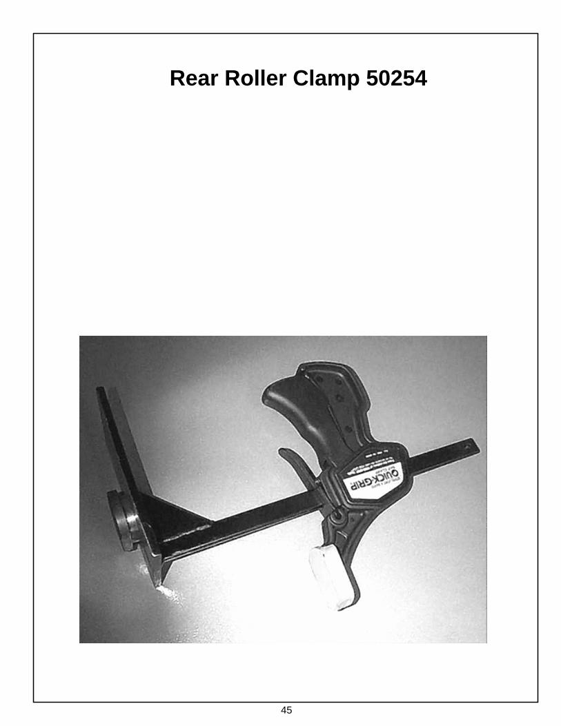
Rear Roller Clamp 50254
46
12 3
47
48
49
50
51
52
53
54
55

56
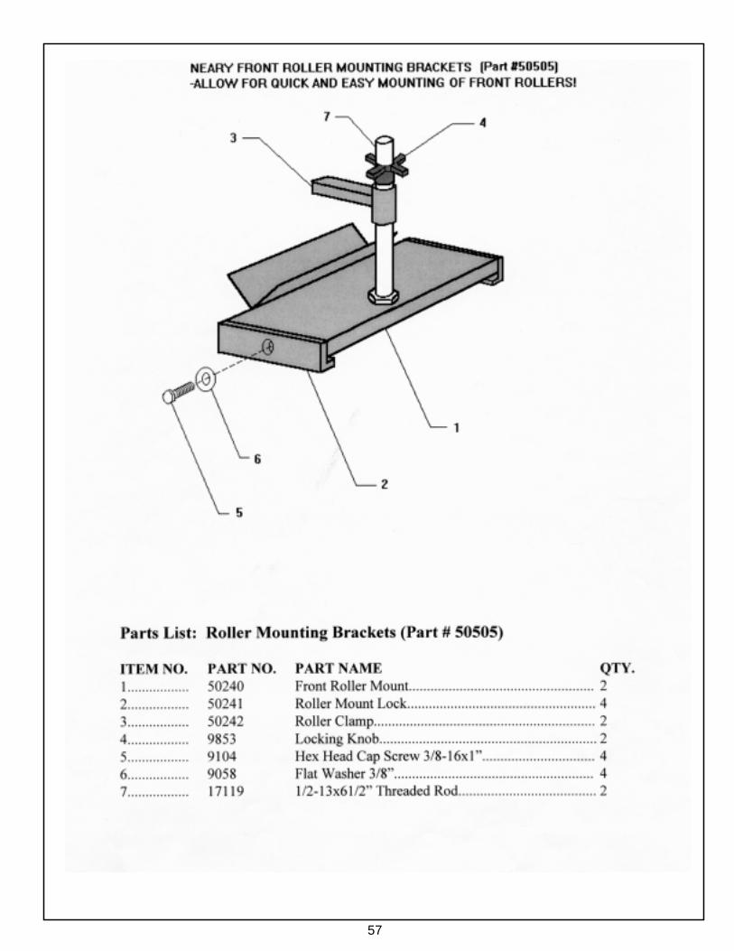
57
58
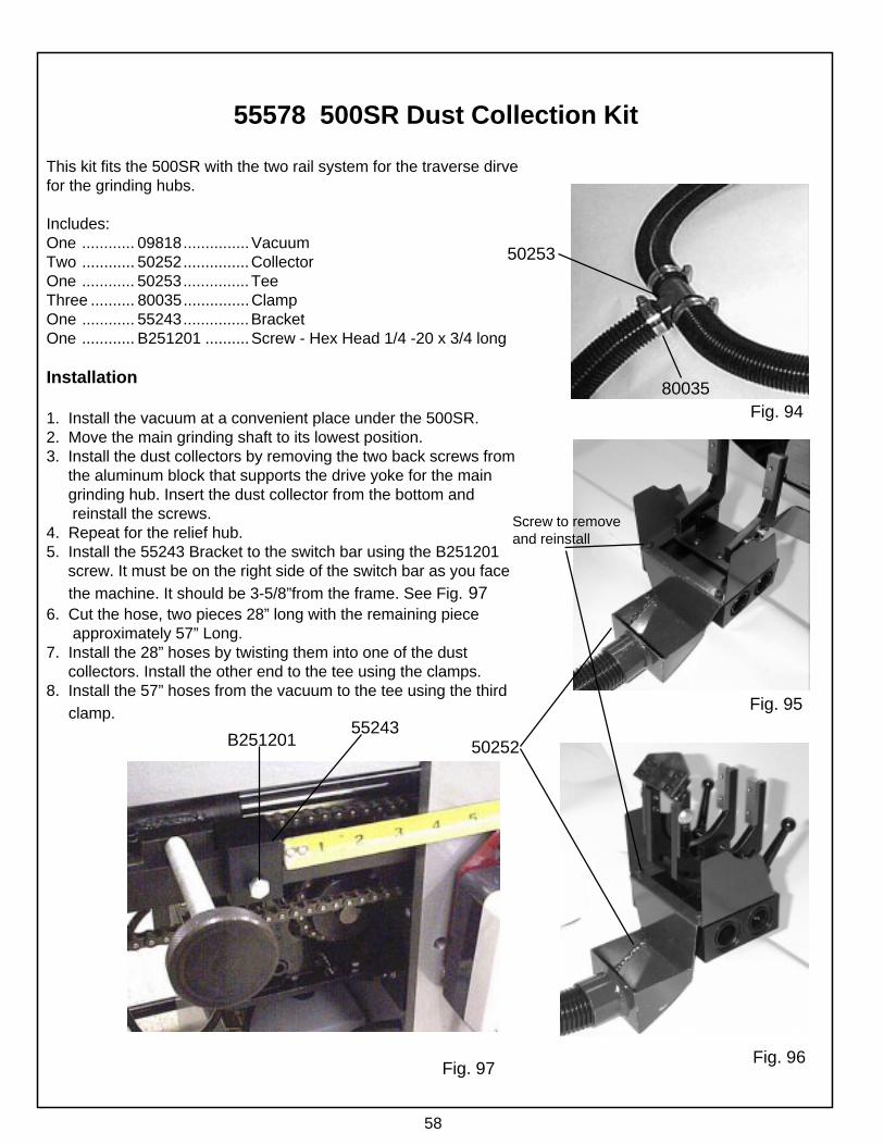
55578 500SR Dust Collection Kit
This kit fits the 500SR with the two rail system for the traverse dirvefor the grinding hubs.
Includes:One ............ 09818...............VacuumTwo ............ 50252...............CollectorOne ............ 50253...............TeeThree .......... 80035...............ClampOne ............ 55243...............BracketOne ............ B251201 ..........Screw - Hex Head 1/4 -20 x 3/4 long
Installation
1. Install the vacuum at a convenient place under the 500SR.2. Move the main grinding shaft to its lowest position.3. Install the dust collectors by removing the two back screws from the aluminum block that supports the drive yoke for the main grinding hub. Insert the dust collector from the bottom and reinstall the screws.4. Repeat for the relief hub.5. Install the 55243 Bracket to the switch bar using the B251201 screw. It must be on the right side of the switch bar as you face the machine. It should be 3-5/8”from the frame. See Fig. 976. Cut the hose, two pieces 28” long with the remaining piece approximately 57” Long.7. Install the 28” hoses by twisting them into one of the dust collectors. Install the other end to the tee using the clamps.8. Install the 57” hoses from the vacuum to the tee using the third clamp.
Fig. 94
Fig. 95
Fig. 96Fig. 97
B25120155243
50252
Screw to removeand reinstall
80035
50253