MODULAR MILLING SYSTEM - Haimer GmbH · For the first time, a modular milling system can achieve...
44
MODULAR MILLING SYSTEM www.haimer-usa.com INCH SIZES Coming Soon!
Transcript of MODULAR MILLING SYSTEM - Haimer GmbH · For the first time, a modular milling system can achieve...

MODULAR MILLING SYSTEM
www.haimer-usa.com
INCH SIZES Coming Soon!

2
T A B L E O F C O N T E N T S
DUO-LOCK™ Page
Characteristics and Advantages 6
Explanation of Icons and Material List 8
Duo-Lock™ Milling Heads
Duo-Lock™ Power Mill Uni Z2 V2002UK Ball Nose – Short version 10
Duo-Lock™ Power Mill Uni Z3 F2003 – Short version (0.75 x D) 12
Duo-Lock™ Power Mill Uni Z3 F2003 – Normal version (1.5 x D) 14
Duo-Lock™ Power Mill Uni Z4 F2304UK – Short version (0.75 x D) 16
Duo-Lock™ Power Mill Uni Z4 F2304MN – Normal version (1.5 x D) 18
Duo-Lock™ Power Mill Uni Z5 F1105MN Chamfer with chip breaker – Normal version (1.5 x D) 20
Duo-Lock™ Power Mill Uni Z5 F1105LL Chamfer with chip breaker – Long version (3 x D) 22
Duo-Lock™ Power Mill Uni Z6/8 E1016/E1018 Chamfering End Mill 24
Duo-Lock™ Basic Z4 F2004UK Chamfer – Short version (0.75 x D) 26
Duo-Lock™ Basic Z4 F2004MN Chamfer – Normal version (1.5 x D) 28
Duo-Lock™ Blanks
Duo-Lock™ Blanks – Short version 30
Duo-Lock™ Blanks – Normal version 31
Duo-Lock™ Blanks – Wrench flat specifications 32
Duo-Lock™ Extensions
Duo-Lock™ Extensions – Cylindrical 34
Duo-Lock™ Extensions – Conical 36
Duo-Lock™ Monoblock holder
Duo-Lock™ Monoblock holder DIN 69871 SK40 38
Duo-Lock™ Monoblock holder DIN 69871 SK50 39
Duo-Lock™ Monoblock holder DIN 69893 HSK-A63 40
Duo-Lock™ Torque Master
Duo-Lock™ Torque Master 41
Duo-Lock™ Torque Master Inserts 42

3
HAIMER DUO-λOCK®
Tooling Technology
Measuring InstrumentsBalancing TechnologyShrinking Technology
Haimer USA, LLC | 134 E. Hill Street | Villa Park, IL 60181 | +1-630-833-1500 | [email protected] | www.haimer-usa.com
HAIMER
Breakthrough Interface – Greater Strength for Increased Performance

4
F O R M U L A S – M I L L I N G B A S I C S
Description Formula Legend
RPMae = Radial cutting width [mm]
ap = Axial cutting depth [mm]
D = Diameter [mm]
fn = Feed per rotation [mm/r]
fz = Feed per tooth [mm/Z]
hm = Average chip thickness [mm]
kc = Specific cutting force [N/mm²]
l = Length of cut [mm]
n = Rounds per minute [rpm]
Pa = Drive power [kW]
Q = Material removal rate [cm3/min]
Tc = Cutting time [min]
vc = Cutting speed [m/min]
vf = Feed rate [mm/min]
z = Number of teeth
= 3.14...
= Efficiency rate
Cutting Speed
Feed per Tooth
Feed per Rotation
Feed Rate
Material Removal Rate
Drive Power
Cutting Time
Average Chip Thickness
Cutting Speed, Feed and Milling
n

5
HAIMER Power Mill with SAFE-λOCK®:
Tooling Technology
HAIMER Power Mill with
The only true solution for roughing and trochoidal milling operations in the industry
Measuring Instruments
Balancing Technology
Shrinking Technology
Haimer USA, LLC | 134 E. Hill Street | Villa Park, IL 60181 | +1-630-833-1500 | [email protected] | www.haimer-usa.com
6
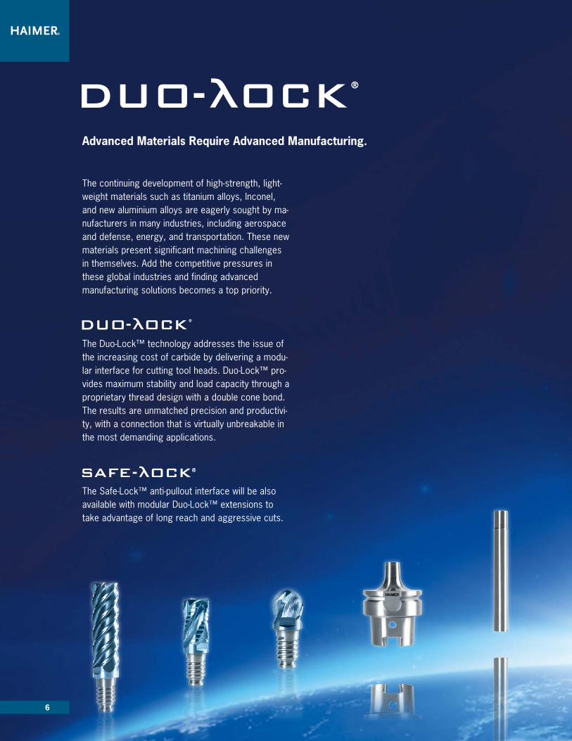
Advanced Materials Require Advanced Manufacturing.
The continuing development of high-strength, light-weight materials such as titanium alloys, Inconel, and new aluminium alloys are eagerly sought by ma-nufacturers in many industries, including aerospace and defense, energy, and transportation. These new materials present significant machining challenges in themselves. Add the competitive pressures in these global industries and finding advanced manufacturing solutions becomes a top priority.
The Duo-Lock™ technology addresses the issue of the increasing cost of carbide by delivering a modu-lar interface for cutting tool heads. Duo-Lock™ pro-vides maximum stability and load capacity through a proprietary thread design with a double cone bond. The results are unmatched precision and productivi-ty, with a connection that is virtually unbreakable in the most demanding applications.
The Safe-Lock™ anti-pullout interface will be also available with modular Duo-Lock™ extensions to take advantage of long reach and aggressive cuts.

7
Advanced Materials Require Advanced Manufacturing.
For the first time, a modular milling system can achieve the same high performance of the latest generation solid carbide end mill.
Duo-Lock™ maximizes a carbide tool’s full potential with productivity gains in both roughing and finishing. It provi-des high load capacity and rigidity when machining at high metal removal rates. When combined with high-per-formance cutting tools, Duo-Lock™ provides more than double the metal removal rate in common milling applica-tions.
Geometric parameters of the connection have been optimized and thoroughly tested, leading to the most robust modular system ever developed.
Superior rigidity of the interface allows for greater depths of cut up to 1.5xD in full slotting.
FEA based design ensures that stress levels in the interface remain below critical values even at elevated loads.
The double cone surfaces, combined with an additional third supporting pilot, delivers high stiffness and accuracy.

8
Characteristics
Application
Coolant
Explanation of Icons
Explanation of Part Numbers
DL F 1 0 0 2 U K 0600 S 0.50 A ADuo-Lock™ Size
Tool Type Group Group Type Variant No. of Teeth Length of Cut Overall Length Diameter Cutting Edge Cutting Edge Size Substrate Coating
DL10DL12DL16DL20DL25DL32
F- Milling cutter-VHMV- Copy mill carbideE- Chamfering end mill
1- Uni2- Basic4- Alu
0- Plain cutter cyl. 1- Chip breaker3- Roughing cutter
0- V0 2- Z2 3- Z3 4- Z4 5- Z5 6- Z6
U- Short (L1= 0.75 x D)M- Normal (L1= 1.5 x D)L- Long (L1= 3 x D1)
K- ShortN- NormalL- Long
0600- Metric
S- Sharp cutting edgeC- Corner chamferR- Corner radiusW- Angle
60- Cone angle0.50- Radius Size
A-D Finegrain carbide
A- PVD
A P P E N D I X
S R
Helix angle Sharp cutting edge Corner chamfer Corner radius
Cool
Fla
sh
Air
Feed direction
Emulsion
Feed direction
Cool Flash
Ramping
Cold air
Slotting
Dry machining
Side milling
Minimal lubrication
Ball Nose
Safe- ock®
Z=5
Teeth 2 Teeth 4 Teeth 5Teeth 3
Z=2
VR
Straight shank
HA
Teeth 6
Z=6
Drilling 3D Milling
MQL
Dry

9
Explanation of Part Numbers
DL F 1 0 0 2 U K 0600 S 0.50 A ADuo-Lock™ Size
Tool Type Group Group Type Variant No. of Teeth Length of Cut Overall Length Diameter Cutting Edge Cutting Edge Size Substrate Coating
DL10DL12DL16DL20DL25DL32
F- Milling cutter-VHMV- Copy mill carbideE- Chamfering end mill
1- Uni2- Basic4- Alu
0- Plain cutter cyl. 1- Chip breaker3- Roughing cutter
0- V0 2- Z2 3- Z3 4- Z4 5- Z5 6- Z6
U- Short (L1= 0.75 x D)M- Normal (L1= 1.5 x D)L- Long (L1= 3 x D1)
K- ShortN- NormalL- Long
0600- Metric
S- Sharp cutting edgeC- Corner chamferR- Corner radiusW- Angle
60- Cone angle0.50- Radius Size
A-D Finegrain carbide
A- PVD
Material Groups
Work Material Material Information
ANSI
Tensile Strength
Content/Hardness
P1 General and Mild Steels 1015, 1045, 4140, 4340 800 N/mm² up to 25 HRC
P2 Die Steels D2, A2, H13, S7 > 800 N/mm² up to 45 HRC
M1 Stainless Steels 303, 304 650 N/mm²
M2 Stainless Steels 17-4PH, 15-5PH, 316L > 650 N/mm²
K1 Cast Iron ASTM A48 NO. 30, ASTM A48 NO. 55/60, G1800 450 N/mm²
K2 Ductile Iron ASTM A536 80-55-06, ASTM A536 100-70-03 > 450 N/mm²
N1 Aluminium Alloys A5005, A6061, A7075
N2 Cast Aluminium Alloys A310, A400 Si > 12%
S1 Titanium & Titanium Alloys B265, B338, B348, Ti6AL4V
S2 High Temp Alloys Inconel, Hastelloy 800 – 1700 N/mm²
H1 Hardened Steels H13, S7 45-50 HRC
H2 Hardened Steels D2, A2, CPM-10V 50-55 HRC
Material List

10
Cutting data are reference values and need to be adjusted according to the application.
Material Groups
Work Material Material Information
ANSI
Tensile Strength
Content/Hardness
Roughing Vc (m/min)
FinishingVc (m/min)
P1 General and Mild Steels 1015, 1045, 4140, 4340 800 N/mm² up to 25 HRC 160 – 220 220 – 280
P2 Die Steels D2, A2, H13, S7 > 800 N/mm² up to 45 HRC 120 – 160 160 – 200
M1 Stainless Steels 303, 304 650 N/mm² 80 – 120 120 – 160
M2 Stainless Steels 17-4PH, 15-5PH, 316L > 650 N/mm² 60 – 90 90 – 120
K1 Cast Iron ASTM A48 NO. 30, ASTM A48 NO. 55/60, G1800 450 N/mm² 120 – 180 180 – 240
K2 Ductile Iron ASTM A536 80-55-06,ASTM A536 100-70-03 > 450 N/mm² 80 – 160 160 – 220
S1 Titanium & Titanium Alloys B265, B338, B348, Ti6AL4V 40 – 80 40 – 80
S2 High Temp Alloys Inconel, Hastelloy 800 – 1700 N/ mm² 30 – 40 30 – 40
N1 Aluminium Alloys A5005, A6061, A7075 500 – 900 500 – 900
N2 Cast Aluminium Alloys A310, A400 Si > 12% 120 – 350 120 – 350
D U O -λO C K ® P O W E R M I L L U N I Z 2V 2 0 0 2 U K B A L L N O S E
S H O R T V E R S I O N
Cutting Data
Feed per tooth (mm/tooth) in relation with D1 and cutting width ae
ø 10 ø 12 ø 16 ø 20
fz 0.03 – 0.09 0.03 – 0.10 0.04 – 0.12 0.05 – 0.13
Cutting data is based on short cylindrical extensions. Cutting data for long overhang needs to be adjusted.
Technical data subject to change without prior notice

11
Application Range - Material*
*See HAIMER material page 9
• For all steel materials• For roughing and finishing• Copy milling
D U O -λO C K ® P O W E R M I L L U N I Z 2V 2 0 0 2 U K B A L L N O S ES H O R T V E R S I O N
Cool
Fla
sh
Characteristics Application Coolant
Air
Technical Data and Product Characteristics
Main Material also suitable for
32°34°
Necked for greater cutting depths Ball Nose Fine balanced Best length repeatability
Part Number HAIMER Quality Duo-LockSize
D1 (f9) [mm]
Cutting Edge Size[mm]
L1 max. [mm]
L [mm]
D2 [mm]
AF[mm]
Torque[N/m]
DL10V2002UK1000R.. DA DL10 10.00 R 5.00 7.5 12.5 9.6 SW8 25
DL12V2002UK1200R.. DA DL12 12.00 R 6.00 9 15 11.5 SW9.5 30
DL16V2002UK1600R.. DA DL16 16.00 R 8.00 12 20 15.5 SW13 60
DL20V2002UK2000R.. DA DL20 20.00 R 10.00 15 25 19.3 SW16 80
VR
Z=2
P
SWDL
R
D2D1
L(1.25xØ)
L1(0.75xØ)
Cutting Data
K S N M
Dry
MQL
Order code = Article Code + HAIMER Quality. Technical data subject to change without prior notice

12
Cutting data are reference values and need to be adjusted according to the application.
Feed per tooth (mm/tooth) in relation with D1 and cutting width ae
ø 10 ø 12 ø 16 ø 20
fz 0.03 – 0.09 0.03 – 0.10 0.04 – 0.12 0.05 – 0.13
Material Groups
Work Material Material Information
ANSI
Tensile Strength
Content/Hardness
Roughing Vc (m/min)
FinishingVc (m/min)
P1 General and Mild Steels 1015, 1045, 4140, 4340 800 N/mm² up to 25 HRC 160 – 220 220 – 280
P2 Die Steels D2, A2, H13, S7 > 800 N/mm² up to 45 HRC 120 – 160 160 – 200
M1 Stainless Steels 303, 304 650 N/mm² 80 – 120 120 – 160
M2 Stainless Steels 17-4PH, 15-5PH, 316L > 650 N/mm² 60 – 90 90 – 120
K1 Cast Iron ASTM A48 NO. 30, ASTM A48 NO. 55/60, G1800 450 N/mm² 120 – 180 180 – 240
K2 Ductile Iron ASTM A536 80-55-06,ASTM A536 100-70-03 > 450 N/mm² 80 – 160 160 – 220
S1 Titanium & Titanium Alloys B265, B338, B348, Ti6AL4V 40 – 80 40 – 80
S2 High Temp Alloys Inconel, Hastelloy 800 – 1700 N/ mm² 30 – 40 30 – 40
N1 Aluminium Alloys A5005, A6061, A7075 500 – 900 500 – 900
N2 Cast Aluminium Alloys A310, A400 Si > 12% 120 – 350 120 – 350
D U O -λO C K ® P O W E R M I L L U N I Z 3F 2 0 0 3
S H O R T V E R S I O N ( 0 . 7 5 X D )
Cutting Data
Cutting data is based on short cylindrical extensions. Cutting data for long overhang needs to be adjusted.
Technical data subject to change without prior notice

13
Application Range - Material*
*See HAIMER material page 9
• Can be used for almost all materials• For roughing and finishing
• Can be used for almost all materials• For roughing and finishing
D U O -λO C K ® P O W E R M I L L U N I Z 3 F 2 0 0 3S H O R T V E R S I O N ( 0 . 7 5 X D )
P
S Cool
Fla
sh
Necked for greater cutting depths Center cutting Unequal cutting edge Fine balanced
Best length repeatability
Characteristics Application Coolant
Air
Technical Data and Product Characteristics
Main Material also suitable for
Order code = Article Code + HAIMER Quality.
35°
36°37°
Cutting Data
Part Number HAIMER Quality Duo-Lock Size
D1 (f9) [mm]
Cutting Edge L1 max. [mm]
L [mm]
D2 [mm]
AF[mm]
Torque[N/m]
DL10F2003UK1000S.. DA DL10 10.00 S 7.5 12.5 9.6 SW8 25
DL12F2003UK1200S.. DA DL12 12.00 S 9 15 11.5 SW9.5 30
DL16F2003UK1600S.. DA DL16 16.00 S 12 20 15.5 SW13 60
DL20F2003UK2000S.. DA DL20 20.00 S 15 25 19.3 SW16 80
S
DLSW
L(1.25xØ)L1
(0.75xØ)
D21
D
K S N M
Dry
MQL
Technical data subject to change without prior notice

14
D U O -λO C K ® P O W E R M I L L U N I Z 3F 2 0 0 3
N O R M A L V E R S I O N ( 1 . 5 X D )
Cutting Data
Cutting data are reference values and need to be adjusted according to the application.
Feed per tooth (mm/tooth) in relation with D1 and cutting width ae
ø 10 ø 12 ø 16 ø 20
fz 0.03 – 0.09 0.03 – 0.10 0.04 – 0.12 0.05 – 0.13
Material Groups
Work Material Material Information
ANSI
Tensile Strength
Content/Hardness
Roughing Vc (m/min)
FinishingVc (m/min)
P1 General and Mild Steels 1015, 1045, 4140, 4340 800 N/mm² up to 25 HRC 160 – 220 220 – 280
P2 Die Steels D2, A2, H13, S7 > 800 N/mm² up to 45 HRC 120 – 160 160 – 200
M1 Stainless Steels 303, 304 650 N/mm² 80 – 120 120 – 160
M2 Stainless Steels 17-4PH, 15-5PH, 316L > 650 N/mm² 60 – 90 90 – 120
K1 Cast Iron ASTM A48 NO. 30, ASTM A48 NO. 55/60, G1800 450 N/mm² 120 – 180 180 – 240
K2 Ductile Iron ASTM A536 80-55-06,ASTM A536 100-70-03 > 450 N/mm² 80 – 160 160 – 220
S1 Titanium & Titanium Alloys B265, B338, B348, Ti6AL4V 40 – 80 40 – 80
S2 High Temp Alloys Inconel, Hastelloy 800 – 1700 N/ mm² 30 – 40 30 – 40
N1 Aluminium Alloys A5005, A6061, A7075 500 – 900 500 – 900
N2 Cast Aluminium Alloys A310, A400 Si > 12% 120 – 350 120 – 350
Cutting data is based on short cylindrical extensions. Cutting data for long overhang needs to be adjusted.
Technical data subject to change without prior notice

15
Application Range - Material*
*See HAIMER material page 9
• Can be used for almost all materials• For roughing and finishing
D U O -λO C K ® P O W E R M I L L U N I Z 3F 2 0 0 3N O R M A L V E R S I O N ( 1 . 5 X D )
P
S Cool
Fla
sh
Necked for greater cutting depths Center cutting Unequal cutting edge Fine balanced
Best length repeatability
Characteristics Application Coolant
Air
Technical Data and Product Characteristics
Main Material also suitable for
Order code = Article Code + HAIMER Quality.
35°
36°37°
Cutting Data
Part Number HAIMER Quality Duo-Lock Size
D1 (f9) [mm]
Cutting Edge L1 max. [mm]
L [mm]
D2 [mm]
AF[mm]
Torque[N/m]
DL10F2003MN1000S.. DA DL10 10.00 S 15 20 9.6 SW8 25
DL12F2003MN1200S.. DA DL12 12.00 S 18 24 11.5 SW9.5 30
DL16F2003MN1600S.. DA DL16 16.00 S 24 32 15.5 SW13 60
DL20F2003MN2000S.. DA DL20 20.00 S 30 40 19.3 SW16 80
S
DLSW
L(2xØ)
L1(1.5xØ)
D2D1
K S N M
Dry
MQL
Technical data subject to change without prior notice

16
D U O -λO C K ® P O W E R M I L L U N I Z 4F 2 3 0 4 U K C O R D P R O F I L E
S H O R T V E R S I O N ( 0 . 7 5 X D )
Cutting Data Technical Data and Product Characteristics
Cutting data are reference values and need to be adjusted according to the application.
Feed per tooth (mm/tooth) in relation with D1 and cutting width ae
ø 10 ø 12 ø 16 ø 20
fz 0.03 – 0.09 0.03 – 0.10 0.04 – 0.12 0.05 – 0.13
Material Groups
Work Material Material Information
ANSI
Tensile Strength
Content/Hardness
Roughing Vc (m/min)
FinishingVc (m/min)
P1 General and Mild Steels 1015, 1045, 4140, 4340 800 N/mm² up to 25 HRC 160 – 220 220 – 280
P2 Die Steels D2, A2, H13, S7 > 800 N/mm² up to 45 HRC 120 – 160 160 – 200
M1 Stainless Steels 303, 304 650 N/mm² 80 – 120 120 – 160
M2 Stainless Steels 17-4PH, 15-5PH, 316L > 650 N/mm² 60 – 90 90 – 120
K1 Cast Iron ASTM A48 NO. 30, ASTM A48 NO. 55/60, G1800 450 N/mm² 120 – 180 180 – 240
K2 Ductile Iron ASTM A536 80-55-06,ASTM A536 100-70-03 > 450 N/mm² 80 – 160 160 – 220
S1 Titanium & Titanium Alloys B265, B338, B348, Ti6AL4V 40 – 80 40 – 80
S2 High Temp Alloys Inconel, Hastelloy 800 – 1700 N/ mm² 30 – 40 30 – 40
N1 Aluminium Alloys A5005, A6061, A7075 500 – 900 500 – 900
N2 Cast Aluminium Alloys A310, A400 Si > 12% 120 – 350 120 – 350
Cutting data is based on short cylindrical extensions. Cutting data for long overhang needs to be adjusted.
Technical data subject to change without prior notice

17
Application Range - Material*
*See HAIMER material page 9
• For almost all materials• For applications with chip evacuation issues• Also for low power machines
D U O -λO C K ® P O W E R M I L L U N I Z 4F 2 3 0 4 U K C O R D P R O F I L ES H O R T V E R S I O N ( 0 . 7 5 X D )
Cool
Fla
sh
Necked for greater cutting depths Center cutting Unequal cutting edge Fine balanced Best length repeatability
Characteristics Application Coolant
Air
HaupteinsatzHaupteinsatz
auch geeignet fürauch geeignet für
P
Part Number HAIMER Quality Duo-Lock Size
D1 (f9) [mm]
Cutting Edge Size[mm]
L1 max. [mm]
L [mm]
D2 [mm]
AF[mm]
Torque[N/m]
DL10F2304UK1000C.. DA DL10 10.00 C 0.30 7.5 12.5 9.6 SW8 25
DL12F2304UK1200C.. DA DL12 12.00 C 0.30 9 15 11.5 SW9.5 30
DL16F2304UK1600C.. DA DL16 16.00 C 0.50 12 20 15.5 SW13 60
DL20F2304UK2000C.. DA DL20 20.00 C 0.60 15 25 19.3 SW16 80
Cutting Data Technical Data and Product Characteristics
Main Material also suitable for
Order code = Article Code + HAIMER Quality.
32°35°
C
SWDL
1D
L1(0.75xØ)
L(1.25xØ)
D2
K S N M
Dry
MQL
Technical data subject to change without prior notice

18
D U O -λO C K ® P O W E R M I L L U N I Z 4F 2 3 0 4 M N C O R D P R O F I L E
N O R M A L V E R S I O N ( 1 . 5 X D )
Cutting Data Technical Data and Product Characteristics
Cutting data are reference values and need to be adjusted according to the application.
Feed per tooth (mm/tooth) in relation with D1 and cutting width ae
ø 10 ø 12 ø 16 ø 20
fz 0.03 – 0.09 0.03 – 0.10 0.04 – 0.12 0.05 – 0.13
Material Groups
Work Material Material Information
ANSI
Tensile Strength
Content/Hardness
Roughing Vc (m/min)
FinishingVc (m/min)
P1 General and Mild Steels 1015, 1045, 4140, 4340 800 N/mm² up to 25 HRC 160 – 220 220 – 280
P2 Die Steels D2, A2, H13, S7 > 800 N/mm² up to 45 HRC 120 – 160 160 – 200
M1 Stainless Steels 303, 304 650 N/mm² 80 – 120 120 – 160
M2 Stainless Steels 17-4PH, 15-5PH, 316L > 650 N/mm² 60 – 90 90 – 120
K1 Cast Iron ASTM A48 NO. 30, ASTM A48 NO. 55/60, G1800 450 N/mm² 120 – 180 180 – 240
K2 Ductile Iron ASTM A536 80-55-06,ASTM A536 100-70-03 > 450 N/mm² 80 – 160 160 – 220
S1 Titanium & Titanium Alloys B265, B338, B348, Ti6AL4V 40 – 80 40 – 80
S2 High Temp Alloys Inconel, Hastelloy 800 – 1700 N/ mm² 30 – 40 30 – 40
N1 Aluminium Alloys A5005, A6061, A7075 500 – 900 500 – 900
N2 Cast Aluminium Alloys A310, A400 Si > 12% 120 – 350 120 – 350
Cutting data is based on short cylindrical extensions. Cutting data for long overhang needs to be adjusted.
Technical data subject to change without prior notice

19
Application Range - Material*
*See HAIMER material page 9
• For almost all materials• For applications with chip evacuation issues• Also for low power machines
D U O -λO C K ® P O W E R M I L L U N I Z 4F 2 3 0 4 M N C O R D P R O F I L EN O R M A L V E R S I O N ( 1 . 5 X D )
Cool
Fla
sh
Necked for greater cutting depths Center cutting Unequal cutting edge Fine balanced Best length repeatability
Characteristics Application Coolant
Air
HaupteinsatzHaupteinsatz
auch geeignet fürauch geeignet für
P
Cutting Data Technical Data and Product Characteristics
Main Material also suitable for
Order code = Article Code + HAIMER Quality.
32°35°
Part Number HAIMER Quality Duo-Lock Size
D1 (f9) [mm]
Cutting Edge Size[mm]
L1 max. [mm]
L [mm]
D2 [mm]
AF[mm]
Torque[N/m]
DL10F2304MN1000C.. DA DL10 10.00 C 0.30 15 20 9.6 SW8 25
DL12F2304MN1200C.. DA DL12 12.00 C 0.30 18 24 11.5 SW9.5 30
DL16F2304MN1600C.. DA DL16 16.00 C 0.50 24 32 15.5 SW13 60
DL20F2304MN2000C.. DA DL20 20.00 C 0.60 30 40 19.3 SW16 80
C
DLSW
D21
D
L(2xØ)L1
(1.5xØ)
K S N M
Dry
MQL
Technical data subject to change without prior notice

20
D U O -λO C K ® P O W E R M I L L U N I Z 5F1105MN CHAMFER WITH CHIP BREAKER
NORMAL VERSION (1 .5 X D)
Feed per tooth (mm/tooth) in relation with D1 and cutting width ae
ø 10 ø 12 ø 16 ø 20 ø 25 ø 32
fz 0.03 – 0.09 0.03 – 0.10 0.04 – 0.12 0.05 – 0.13 0.06 – 0.17 0.07 – 0.20
Cutting Data
Cutting data is based on short cylindrical extensions. Cutting data for long overhang needs to be adjusted.
Cutting data are reference values and need to be adjusted according to the application.
Material Groups
Work Material Material Information
ANSI
Tensile Strength
Content/Hardness
Roughing Vc (m/min)
FinishingVc (m/min)
P1 General and Mild Steels 1015, 1045, 4140, 4340 800 N/mm² up to 25 HRC 160 – 220 220 – 280
P2 Die Steels D2, A2, H13, S7 > 800 N/mm² up to 45 HRC 120 – 160 160 – 200
M1 Stainless Steels 303, 304 650 N/mm² 80 – 120 120 – 160
M2 Stainless Steels 17-4PH, 15-5PH, 316L > 650 N/mm² 60 – 90 90 – 120
K1 Cast Iron ASTM A48 NO. 30, ASTM A48 NO. 55/60, G1800 450 N/mm² 120 – 180 180 – 240
K2 Ductile Iron ASTM A536 80-55-06,ASTM A536 100-70-03 > 450 N/mm² 80 – 160 160 – 220
S1 Titanium & Titanium Alloys B265, B338, B348, Ti6AL4V 40 – 80 40 – 80
S2 High Temp Alloys Inconel, Hastelloy 800 – 1700 N/ mm² 30 – 40 30 – 40
N1 Aluminium Alloys A5005, A6061, A7075 500 – 900 500 – 900
N2 Cast Aluminium Alloys A310, A400 Si > 12% 120 – 350 120 – 350
Technical data subject to change without prior notice

21
Application Range - Material*
*See HAIMER material page 9
• Can be used for almost all materials• HSC finishing up to 1.5 x D1• Excellent for trochoidal milling
D U O -λO C K ® P O W E R M I L L U N I Z 5F1105MN CHAMFER WITH CHIP BREAKERN ORMAL VERSION (1 .5 X D )
Cool
Fla
sh
Necked for greater cutting depths Unequal cutting edge Fine balanced Best length repeatability Polished gullets Chip breaker
Characteristics Application Coolant
Air
auch geeignet für
P
Z=5
Cutting Data Technical Data and Product Characteristics
Main Material also suitable for
46°47°
K S N
Part Number HAIMER Quality Duo-Lock Size
D1 (f9)[mm]
Cutting Edge Size[mm]
L1 max.[mm]
L[mm]
D2[mm]
AF[mm]
Torque[N/m]
DL10F1105MN1000C.. DA DL10 10.00 C 0.30 15 20 9.6 SW8 25
DL12F1105MN1200C.. DA DL12 12.00 C 0.30 18 24 11.5 SW9.5 30
DL16F1105MN1600C.. DA DL16 16.00 C 0.50 24 32 15.5 SW13 60
DL20F1105MN2000C.. DA DL20 20.00 C 0.60 30 40 19.3 SW16 80
DL25F1105MN2500C.. DA DL25 25.00 C 0.60 37.5 50 24.0 SW21 100
DL32F1105MN3200C.. DA DL32 32.00 C 0.70 48 64 31.0 SW28 130
M
C
DLSW
D2D1
L1(1.5xØ)
L(2xØ)
Dry
MQL
Technical data subject to change without prior notice

22
D U O -λO C K ® P O W E R M I L L U N I Z 5F1105LL CHAMFER WITH CHIP BREAKER
LONG VERSION (3 X D )
Cutting Data
Feed per tooth (mm/tooth) in relation with D1 and cutting width ae
ø 10 ø 12 ø 16 ø 20 ø 25 ø 32
fz 0.03 – 0.09 0.03 – 0.10 0.04 – 0.12 0.05 – 0.13 0.06 – 0.17 0.07 – 0.20
Cutting data is based on short cylindrical extensions. Cutting data for long overhang needs to be adjusted.
Cutting data are reference values and need to be adjusted according to the application.
Material Groups
Work Material Material Information
ANSI
Tensile Strength
Content/Hardness
Finishing Vc (m/min)
P1 General and Mild Steels 1015, 1045, 4140, 4340 800 N/mm² up to 25 HRC 220 – 280
P2 Die Steels D2, A2, H13, S7 > 800 N/mm² up to 45 HRC 160 – 200
M1 Stainless Steels 303, 304 650 N/mm² 120 – 160
M2 Stainless Steels 17-4PH, 15-5PH, 316L > 650 N/mm² 90 – 120
K1 Cast Iron ASTM A48 NO. 30, ASTM A48 NO. 55/60, G1800 450 N/mm² 180 – 240
K2 Ductile Iron ASTM A536 80-55-06,ASTM A536 100-70-03 > 450 N/mm² 160 – 220
S1 Titanium & Titanium Alloys B265, B338, B348, Ti6AL4V 40 – 80
S2 High Temp Alloys Inconel, Hastelloy 800 – 1700 N/ mm² 30 – 40
N1 Aluminium Alloys A5005, A6061, A7075 500 – 900
N2 Cast Aluminium Alloys A310, A400 Si > 12% 120 – 350
Technical data subject to change without prior notice

23
D U O -λO C K ® P O W E R M I L L U N I Z 5F1105LL CHAMFER WITH CHIP BREAKERLONG VERSION (3 X D )
Cool
Fla
sh
Necked for greater cutting depths Unequal cutting edge Fine balanced Best length repeatability Polished gullets Chip breaker
Characteristics Application Coolant
AirZ=5
Cutting Data Technical Data and Product Characteristics
46°47°
Part Number HAIMER Quality Duo-Lock Size
D1 (f9) [mm]
Cutting Edge Size[mm]
L1 max. [mm]
L [mm]
D2 [mm]
AF[mm]
Torque[N/m]
DL10F1105LL1000C.. DA DL10 10.00 C 0.30 30 35 9.6 SW8 25
DL12F1105LL1200C.. DA DL12 12.00 C 0.30 36 42 11.5 SW9.5 30
DL16F1105LL1600C.. DA DL16 16.00 C 0.50 48 56 15.5 SW13 60
DL20F1105LL2000C.. DA DL20 20.00 C 0.60 60 70 19.3 SW16 80
DL25F1105LL2500C.. DA DL25 25.00 C 0.60 75 87.5 24.0 SW21 100
DL32F1105LL3200C.. DA DL32 32.00 C 0.70 96 112 31.0 SW28 130
C
DLSW
L(3.5xØ)L1
(3xØ)
D21
D
Application Range - Material*
*See HAIMER material page 9
• For all steel materials• HSC finishing up to 1.5 x D1• Excellent for trochoidal milling
auch geeignet für
PMain Material also suitable for
K S N M
Dry
MQL
Technical data subject to change without prior notice

24
D U O -λO C K ® P O W E R M I L L U N I Z 6 / 8E 1 0 1 6 / E 1 0 1 8 C H A M F E R I N G E N D M I L L
Cutting Data Technical Data and Product Characteristics
Feed per tooth (mm/tooth) in relation with D1 and cutting width ae
ø 10 ø 12 ø 16
fz 0.02 – 0.09 0.03 – 0.10 0.03 – 0.12
Cutting data is based on short cylindrical extensions. Cutting data for long overhang needs to be adjusted.
Cutting data are reference values and need to be adjusted according to the application.
Material Groups
Work Material Material Information
ANSI
Tensile Strength
Content/Hardness
Roughing Vc (m/min)
FinishingVc (m/min)
P1 General and Mild Steels 1015, 1045, 4140, 4340 800 N/mm² up to 25 HRC 160 – 220 220 – 280
P2 Die Steels D2, A2, H13, S7 > 800 N/mm² up to 45 HRC 120 – 160 160 – 200
M1 Stainless Steels 303, 304 650 N/mm² 80 – 120 120 – 160
M2 Stainless Steels 17-4PH, 15-5PH, 316L > 650 N/mm² 60 – 90 90 – 120
K1 Cast Iron ASTM A48 NO. 30, ASTM A48 NO. 55/60, G1800 450 N/mm² 120 – 180 180 – 240
K2 Ductile Iron ASTM A536 80-55-06,ASTM A536 100-70-03 > 450 N/mm² 80 – 160 160 – 220
S1 Titanium & Titanium Alloys B265, B338, B348, Ti6AL4V 40 – 80 40 – 80
S2 High Temp Alloys Inconel, Hastelloy 800 – 1700 N/ mm² 30 – 40 30 – 40
N1 Aluminium Alloys A5005, A6061, A7075 500 – 900 500 – 900
N2 Cast Aluminium Alloys A310, A400 Si > 12% 120 – 350 120 – 350
Technical data subject to change without prior notice

25
D U O -λO C K ® P O W E R M I L L U N I Z 6 / 8E 1 0 1 6 / E 1 0 1 8 C H A M F E R I N G E N D M I L L
Cutting Data
Order code = Article Code + HAIMER Quality.
Application Range - Material*
*See HAIMER material page 9
• For almost all materials• For chamfering of edges, grooves and holes
Cool
Fla
sh
Cone angle 60/90/120° Honed tip plan Best length repeatability
Characteristics Application Coolant
Air
HaupteinsatzHaupteinsatz
auch geeignet fürauch geeignet für
P
Technical Data and Product Characteristics
Main Material also suitable for
K S N
Part Number HAIMER Quality Duo-Lock Size
Z D1 (h6)[mm]
Chamfer Angle L1 max. [mm]
L [mm]
D2[mm]
AF[mm]
Torque[N/m]
DL10E1016UK1000W60.. DA DL10 6 10.00 W 60° 6.9 12.5 2.0 SW8 25
DL10E1016UK1000W90.. DA DL10 6 10.00 W 90° 4 12.5 2.0 SW8 25
DL10E1016UK1000W120.. DA DL10 6 10.00 W 120° 2.3 12.5 2.0 SW8 25
DL12E1016UK1200W60.. DA DL12 6 12.00 W 60° 8.3 15 2.4 SW9.5 30
DL12E1016UK1200W90.. DA DL12 6 12.00 W 90° 4.8 15 2.4 SW9.5 30
DL12E1016UK1200W120.. DA DL12 6 12.00 W 120° 2.7 15 2.4 SW9.5 30
DL16E1018UK1600W60.. DA DL16 8 16.00 W 60° 11 20 3.2 SW13 60
DL16E1018UK1600W90.. DA DL16 8 16.00 W 90° 6.4 20 3.2 SW13 60
DL16E1018UK1600W120.. DA DL16 8 16.00 W 120° 3.6 20 3.2 SW13 60
Z=6/8
W
M
apae DL
W
SW
L
L1
D1
D2
1W
(1.25xØ)
Dry
MQL
Technical data subject to change without prior notice

26
Cutting Data
D U O -λO C K ® B A S I C Z 4F 2 0 0 4 U K C H A M F E R
S H O R T V E R S I O N ( 0 . 7 5 X D )
Technical Data and Product Characteristics
Feed per tooth (mm/tooth) in relation with D1 and cutting width ae
ø 10 ø 12 ø 16 ø 20 ø 25 ø 32
fz 0.03 – 0.09 0.03 – 0.10 0.04 – 0.12 0.05 – 0.13 0.06 – 0.17 0.07 – 0.20
Cutting data is based on short cylindrical extensions. Cutting data for long overhang needs to be adjusted.
Cutting data are reference values and need to be adjusted according to the application.
Material Groups
Work Material Material Information
ANSI
Tensile Strength
Content/Hardness
Roughing Vc (m/min)
FinishingVc (m/min)
P1 General and Mild Steels 1015, 1045, 4140, 4340 800 N/mm² up to 25 HRC 160 – 220 220 – 280
P2 Die Steels D2, A2, H13, S7 > 800 N/mm² up to 45 HRC 120 – 160 160 – 200
M1 Stainless Steels 303, 304 650 N/mm² 80 – 120 120 – 160
M2 Stainless Steels 17-4PH, 15-5PH, 316L > 650 N/mm² 60 – 90 90 – 120
K1 Cast Iron ASTM A48 NO. 30, ASTM A48 NO. 55/60, G1800 450 N/mm² 120 – 180 180 – 240
K2 Ductile Iron ASTM A536 80-55-06,ASTM A536 100-70-03 > 450 N/mm² 80 – 160 160 – 220
S1 Titanium & Titanium Alloys B265, B338, B348, Ti6AL4V 40 – 80 40 – 80
S2 High Temp Alloys Inconel, Hastelloy 800 – 1700 N/ mm² 30 – 40 30 – 40
N1 Aluminium Alloys A5005, A6061, A7075 500 – 900 500 – 900
N2 Cast Aluminium Alloys A310, A400 Si > 12% 120 – 350 120 – 350
Technical data subject to change without prior notice

27
Cutting Data
D U O -λO C K ® B A S I C Z 4F 2 0 0 4 U K C H A M F E RS H O R T V E R S I O N ( 0 . 7 5 X D )
Cool
Fla
sh
Necked for greater cutting depths Center cutting Unequal cutting edge Fine balanced Best length repeatability
Characteristics Application Coolant
Air
Technical Data and Product Characteristics
Order code = Article Code + HAIMER Quality.
Application Range - Material*
*See HAIMER material page 9
• For almost all materials• For roughing and finishing
PMain Material also suitable for
K S NM
31°33°
Part Number HAIMER Quality Duo-Lock Size
D1 (f9) [mm]
Cutting Edge Size[mm]
L1 max. [mm]
L[mm]
D2[mm]
AF[mm]
Torque[N/m]
DL10F2004UK1000C.. DA DL10 10.00 C 0.20 7.5 12.5 9.6 SW8 25
DL12F2004UK1200C.. DA DL12 12.00 C 0.24 9 15 11.5 SW9.5 30
DL16F2004UK1600C.. DA DL16 16.00 C 0.32 12 20 15.5 SW13 60
DL20F2004UK2000C.. DA DL20 20.00 C 0.40 15 25 19.3 SW16 80
DL25F2004UK2500C.. DA DL25 25.00 C 0.50 18.75 31.25 24.0 SW21 100
DL32F2004UK3200C.. DA DL32 32.00 C 0.64 24 40 31.0 SW28 130
(0.02xØ)C
DLSWL1
(0.75xØ)
L(1.25xØ)
D2D1
Cooling with Cool Jet or Cool Flash and using Power Chucks is recommended for longer tool life and increased metal removal rates.
Dry
MQL
Technical data subject to change without prior notice

28
Cutting Data
D U O -λO C K ® B A S I C Z 4F 2 0 0 4 M N C H A M F E R
N O R M A L V E R S I O N ( 1 . 5 X D )
Technical Data and Product Characteristics
Feed per tooth (mm/tooth) in relation with D1 and cutting width ae
ø 10 ø 12 ø 16 ø 20 ø 25 ø 32
fz 0.03 – 0.09 0.03 – 0.10 0.04 – 0.12 0.05 – 0.13 0.06 – 0.17 0.07 – 0.20
Cutting data is based on short cylindrical extensions. Cutting data for long overhang needs to be adjusted.
Cutting data are reference values and need to be adjusted according to the application.
Material Groups
Work Material Material Information
ANSI
Tensile Strength
Content/Hardness
Roughing Vc (m/min)
FinishingVc (m/min)
P1 General and Mild Steels 1015, 1045, 4140, 4340 800 N/mm² up to 25 HRC 160 – 220 220 – 280
P2 Die Steels D2, A2, H13, S7 > 800 N/mm² up to 45 HRC 120 – 160 160 – 200
M1 Stainless Steels 303, 304 650 N/mm² 80 – 120 120 – 160
M2 Stainless Steels 17-4PH, 15-5PH, 316L > 650 N/mm² 60 – 90 90 – 120
K1 Cast Iron ASTM A48 NO. 30, ASTM A48 NO. 55/60, G1800 450 N/mm² 120 – 180 180 – 240
K2 Ductile Iron ASTM A536 80-55-06,ASTM A536 100-70-03 > 450 N/mm² 80 – 160 160 – 220
S1 Titanium & Titanium Alloys B265, B338, B348, Ti6AL4V 40 – 80 40 – 80
S2 High Temp Alloys Inconel, Hastelloy 800 – 1700 N/ mm² 30 – 40 30 – 40
N1 Aluminium Alloys A5005, A6061, A7075 500 – 900 500 – 900
N2 Cast Aluminium Alloys A310, A400 Si > 12% 120 – 350 120 – 350
Technical data subject to change without prior notice

29
Cutting Data
D U O -λO C K ® B A S I C Z 4F 2 0 0 4 M N C H A M F E RN O R M A L V E R S I O N ( 1 . 5 X D )
Cool
Fla
sh
Necked for greater cutting depths Center cutting Unequal cutting edge Fine balanced Best length repeatability
Characteristics Application Coolant
Air
Technical Data and Product Characteristics
Order code = Article Code + HAIMER Quality.
Application Range - Material*
PMain Material also suitable for
K S NM
31°33°
Part Number HAIMER Quality Duo-LockSize
D1 (f9)[mm]
Cutting Edge Size[mm]
L1 max. [mm]
L[mm]
D2[mm]
AF[mm]
Torque[N/m]
DL10F2004MN1000C.. DA DL10 10.00 C 0.20 15 20 9.6 SW8 25
DL12F2004MN1200C.. DA DL12 12.00 C 0.24 18 24 11.5 SW9.5 30
DL16F2004MN1600C.. DA DL16 16.00 C 0.32 24 32 15.5 SW13 60
DL20F2004MN2000C.. DA DL20 20.00 C 0.40 30 40 19.3 SW16 80
DL25F2004MN2500C.. DA DL25 25.00 C 0.50 37.5 50 24.0 SW21 100
DL32F2004MN3200C.. DA DL32 32.00 C 0.64 48 64 31.0 SW28 130
(0.02xØ)C
DLSWL1
(1.5xØ)
L(2xØ)
D21
D
Cooling with Cool Jet or Cool Flash and using Power Chucks is recommended for longer tool life and increased metal removal rates.
*See HAIMER material page 9
• For almost all materials• For roughing and finishing
Dry
MQL
Technical data subject to change without prior notice

30
X
C
DL
4:1XL
(1.25 x )
(L)
D1
X
C
DL
4:1XL
(1.25 x )
(L)
D1
Version: short, without wrench flats – Best length repeatability – Fine grain carbide, 10% cobalt – Roller spanner available upon request
Part Number D1 (h6)[mm]
Cutting Edge Size[mm]
L (+ 1)[mm]
Interface Tightening Torque[Nm]
AF[mm]
Material[mm]
RODL10-D10HA0125-0001 10 C –– 12.5 DL10 25 8 HF10
RODL12-D12HA0150-0001 12 C –– 15 DL12 30 9.5 HF10
RODL16-D16HA0200-0001 16 C –– 20 DL16 60 13 HF10
RODL20-D20HA0250-0001 20 C –– 25 DL20 80 16 HF10
RODL25-D25HA0313-0001 25 C –– 31.25 DL25 100 21 HF10
RODL32-D32HA0400-0001 32 C –– 40 DL32 130 28 HF10
X
C
DL
SW
4:1XL
(1.25 x )
(L)
D1
X
C
DL
SW
4:1XL
(1.25 x )
(L)
D1
Version: short, with wrench flats – Best length repeatability – Fine grain carbide, 10% cobalt
For wrench flat specifications, please see page 32Only suitable for use with Duo-Lock™ Torque Master
Part Number D1 (h6) [mm]
Cutting Edge Size[mm]
L (+ 1)[mm]
Interface Tightening Torque[Nm]
AF[mm]
Material[mm]
RODL10-D10HA0125-0002 10 C –– 12.5 DL10 25 8 HF10
RODL12-D12HA0150-0002 12 C –– 15 DL12 30 9.5 HF10
RODL16-D16HA0200-0002 16 C –– 20 DL16 60 13 HF10
RODL20-D20HA0250-0002 20 C –– 25 DL20 80 16 HF10
RODL25-D25HA0313-0002 25 C –– 31.25 DL25 100 21 HF10
RODL32-D32HA0400-0002 32 C –– 40 DL32 130 28 HF10
Further lengths available on request
D U O -λO C K ® B L A N K – S H O R T V E R S I O N
Technical data subject to change without prior notice

31
X
C
DL
4:1XL
(2 x )
(L)
D1 X
C
DL
4:1XL
(2 x )
(L)
D1
Part Number D1 (h6) [mm]
Cutting Edge Size[mm]
L (+ 1)[mm]
Interface Tightening Torque[Nm]
AF[mm]
Material[mm]
RODL10-D10HA0200-0001 10 C 0.2 20 DL10 25 8 HF10
RODL12-D12HA0240-0001 12 C 0.2 24 DL12 30 9.5 HF10
RODL16-D16HA0320-0001 16 C 0.2 32 DL16 60 13 HF10
RODL20-D20HA0400-0001 20 C 0.2 40 DL20 80 16 HF10
RODL25-D25HA0500-0001 25 C 0.2 50 DL25 100 21 HF10
RODL32-D32HA0640-0001 32 C 0.2 64 DL32 130 28 HF10
Version: normal, without wrench flats – Best length repeatability – Fine grain carbide, 10% cobalt – Roller spanner available upon request
X
C
DL
SW
4:1XL
(2 x )
(L)
D1 X
C
DL
SW
4:1XL
(2 x )
(L)
D1
Part Number D1 (h6) [mm]
Cutting Edge Size[mm]
L (+ 1)[mm]
Interface Tightening Torque[Nm]
AF[mm]
Material[mm]
RODL10-D10HA0200-0002 10 C 0.2 20 DL10 25 8 HF10
RODL12-D12HA0240-0002 12 C 0.2 24 DL12 30 9.5 HF10
RODL16-D16HA0320-0002 16 C 0.2 32 DL16 60 13 HF10
RODL20-D20HA0400-0002 20 C 0.2 40 DL20 80 16 HF10
RODL25-D25HA0500-0002 25 C 0.2 50 DL25 100 21 HF10
RODL32-D32HA0640-0002 32 C 0.2 64 DL32 130 28 HF10
Version: normal, with wrench flats – Best length repeatability – Fine grain carbide, 10% cobalt
For wrench flat specifications, please see page 32Only suitable for use with Duo-Lock™ Torque Master
Further lengths available on request
D U O -λO C K ® B L A N K – N O R M A L V E R S I O N
Technical data subject to change without prior notice

32
D U O -λO C K ® B L A N K – W R E N C H F L A T S P E C I F I C A T I O N S
Interface AF XX[mm]
L [mm]
B[mm]
Ø D1[mm]
RXX[mm]
DL10 8 1.7 2.5 10 0.2
DL12 9.5 2 3 12 0.25
DL16 13 2.5 4 16 0.3
DL20 16 3.125 4.8 20 0.375
DL25 21 4.1 6.3 25 0.45
DL32 28 5.25 8.1 32 0.6
max.25°
DL SW(AF) XX L B øD1 RXXDL10 SW8 1.7 2.5 10 0.2
DL12 SW9.5 2 3 12 0.25
DL16 SW13 2.5 4 16 0.3
DL20 SW16 3.125 4.8 20 0.375
DL25 SW21 4.1 6.3 25 0.45
DL32 SW28 5.25 8.1 32 0.6DL
min. L +0.3
D1
h6
B+0.2-0.1
SW
(AF)
XX -
0.05
RXX0.1
Technical data subject to change without prior notice

33
Tooling Technology
HAIMER Cool Flash:Optimal cooling – Even at the speed of light.
HAIMER Cool Flash
Measuring InstrumentsBalancing TechnologyShrinking Technology
Haimer USA, LLC | 134 E. Hill Street | Villa Park, IL 60181 | +1-630-833-1500 | [email protected] | www.haimer-usa.com

34
D1
D2
L1
D3
DL
L2
D U O -λO C K ® E X T E N S I O N S – C Y L I N D R I C A L – S H O R T
Interface Order No. Clamping Ø Length Neck Ø Neck length Internal bore Ø D1 [mm] L1 [mm] D2 [mm] L2 [mm] D3 [mm]
DL12 75.120.DL12 12 60 11.5 6 2.5DL16 75.160.DL16 16 65 15.5 8 3DL20 75.200.DL20 20 70 19.3 10 3DL25 75.250.DL25 25 80 24 12.5 5DL32 75.320.DL32 32 90 31 16 5
Version: cylindrical, short – Shank tolerance: h5 – With inner coolant bore – Safe-LockTM optional
Duo-Lock™ extensions cylindrical: short
AccessoriesTorque Master Duo-Lock™ incl. grip set long (2 pcs.) Order No. 84.600.20Torque Master Set Duo-Lock™ (with case, insert and grip set, long) Order No. 84.600.20.AKInsertSize DL10 DL12 DL16 DL20 DL25 DL32Order No. 84.640… .10 .12 .16 .20 .25 .32Wear insert Size DL10 DL12 Order No. 84.640… .10.1 .12.1 Grip set long Order No. 84.600.20.1
Torque of Duo-Lock™ interface
DL10 DL12 DL16 DL20 DL25 DL32
Nm 25 30 60 80 100 130
Interface Order No. Clamping Ø Length Neck Ø Neck length Internal bore Ø D1 [mm] L1 [mm] D2 [mm] L2 [mm] D3 [mm]
DL10 75.100.DL10 10 55 9.6 5 2.5DL12 75.121.DL12 12 65 11.5 6 2.5DL16 75.161.DL16 16 70 15.5 8 3DL20 75.201.DL20 20 80 19.3 10 3DL25 75.251.DL25 25 90 24 12.5 5DL32 75.321.DL32 32 105 31 16 5
Duo-Lock™ extensions cylindrical: short with Safe-LockTM
Technical data subject to change without prior notice

35
D1
D2
L1
D3
DL
L2
D U O -λO C K ® E X T E N S I O N S – C Y L I N D R I C A L – L O N G
Version: cylindrical, long – Shank tolerance: h5 – With inner coolant bore – Vibration dampening on request – Safe-LockTM optional – Overall length can be modified
AccessoriesTorque Master Duo-Lock™ incl. grip set long (2 pcs.) Order No. 84.600.20Torque Master Set Duo-Lock™ (with case, insert and grip set, long) Order No. 84.600.20.AKInsertSize DL10 DL12 DL16 DL20 DL25 DL32Order No. 84.640… .10 .12 .16 .20 .25 .32Wear insert Size DL10 DL12 Order No. 84.640… .10.1 .12.1 Grip set long Order No. 84.600.20.1
Interface Order No. Clamping Ø Length Neck Ø Neck length Internal bore Ø D1 [mm] L1 [mm] D2 [mm] L2 [mm] D3 [mm]
DL10 75.102.DL10 10 100 9.6 5 2.5DL12 75.122.DL12 12 120 11.5 6 2.5DL16 75.162.DL16 16 160 15.5 8 3DL20 75.202.DL20 20 200 19.3 10 3DL25 75.252.DL25 25 250 24 12.5 5DL32 75.322.DL32 32 250 31 16 5
Duo-Lock™ extensions cylindrical: long
Torque of Duo-Lock™ interface
DL10 DL12 DL16 DL20 DL25 DL32
Nm 25 30 60 80 100 130
Technical data subject to change without prior notice

36
D1
D2
L1
D3
DL
5°
D U O -λO C K ® E X T E N S I O N S C O N I C A L – S H O R T
Version: conical, short – Shank tolerance: h5 – With inner coolant bore – With Safe-LockTM as standard
Interface Order No. Clamping Ø Length Clamping Ø Internal bore Ø D1 [mm] L1 [mm] D2 [mm] D3 [mm]
DL10 75.120.DL10 12 65 9.6 2.5DL10 75.160.DL10 16 90 9.6 2.5DL10 75.200.DL10 20 115 9.6 2.5DL12 75.160.DL12 16 80 11.5 2.5DL12 75.200.DL12 20 105 11.5 2.5DL16 75.200.DL16 20 80 15.5 3DL16 75.250.DL16 25 115 15.5 3DL20 75.250.DL20 25 95 19.3 3DL25 75.320.DL25 32 105 24 5DL32 75.400.DL32 40 140 31 5DL32 75.500.DL32 50 200 31 5
Duo-Lock™ extensions conical: short with Safe-LockTM
AccessoriesTorque Master Duo-Lock™ incl. grip set long (2 pcs.) Order No. 84.600.20Torque Master Set Duo-Lock™ (with case, insert and grip set, long) Order No. 84.600.20.AKInsertSize DL10 DL12 DL16 DL20 DL25 DL32Order No. 84.640… .10 .12 .16 .20 .25 .32Wear insert Size DL10 DL12 Order No. 84.640… .10.1 .12.1 Grip set long Order No. 84.600.20.1
Torque of Duo-Lock™ interface
DL10 DL12 DL16 DL20 DL25 DL32
Nm 25 30 60 80 100 130
Technical data subject to change without prior notice

37
D1
D2
L1
D3
DL
5°
D U O -λO C K ® E X T E N S I O N S C O N I C A L – L O N G
Interface Order No. Clamping Ø Length Clamping Ø Internal bore Ø D1 [mm] L1 [mm] D2 [mm] D3 [mm]
DL10 75.122.DL10 12 120 9.6 2.5DL10 75.162.DL10 16 160 9.6 2.5DL10 75.202.DL10 20 200 9.6 2.5DL12 75.162.DL12 16 160 11.5 2.5DL12 75.202.DL12 20 200 11.5 2.5DL16 75.202.DL16 20 200 15.5 3DL16 75.252.DL16 25 250 15.5 3DL20 75.252.DL20 25 250 19.3 3DL25 75.322.DL25 32 250 24 5DL32 75.402.DL32 40 250 31 5DL32 75.502.DL32 50 250 31 5
Duo-Lock™ extensions conical: long
Version: conical, long – Shank tolerance: h5 – With inner coolant bore – Vibration dampening on request – Safe-LockTM optional – Overall length can be modified
AccessoriesTorque Master Duo-Lock™ incl. grip set long (2 pcs.) Order No. 84.600.20Torque Master Set Duo-Lock™ (with case, insert and grip set, long) Order No. 84.600.20.AKInsertSize DL10 DL12 DL16 DL20 DL25 DL32Order No. 84.640… .10 .12 .16 .20 .25 .32Wear insert Size DL10 DL12 Order No. 84.640… .10.1 .12.1 Grip set long Order No. 84.600.20.1
Torque of Duo-Lock™ interface
DL10 DL12 DL16 DL20 DL25 DL32
Nm 25 30 60 80 100 130
Technical data subject to change without prior notice

38
A
L2
D1
D2
L1
DL
D U O -λO C K ®
M O N O B L O C K H O L D E RD I N 6 9 8 7 1 · S K 4 0
SK40
Interface DL10 DL12 DL16 DL20 DL25 DL32
Clamping Ø D1 [mm] 10 12 16 20 25 32
Ø D2 [mm] 9.6 11.5 15.5 19.3 24 31
L1 [mm] 21.9 21.9 30.9 30.9 36.9 45.9
L2 [mm] 5 6 8 10 12.5 16
Length A [mm] short 41 41 50 50 56 65Order No. 40.490.DL... .10 .12 .16 .20 .25 .32
Duo-Lock™ Monoblock holder for direct clamping.Perfectly suitable for milling with short overhang.
With steep taper SK40 Form ADB DIN 69871.
Form ADB means: central coolant supply and coolant channels on the collar which can be sealed again.
– All holders incl. inner coolant – Hardened 54-2 HRC
Torque of Duo-Lock™ interface
DL10 DL12 DL16 DL20 DL25 DL32
Nm 25 30 60 80 100 130
AccessoriesTorque Master Duo-Lock™ incl. grip set long (2 pcs.) Order No. 84.600.20Torque Master Set Duo-Lock™ (with case, 6 inserts and grip set, long) Order No. 84.600.20.AKInsertSize DL10 DL12 DL16 DL20 DL25 DL32Order No. 84.640… .10 .12 .16 .20 .25 .32Wear insert Size DL10 DL12 Order No. 84.640… .10.1 .12.1 Grip set long Order No. 84.600.20.1Pull studs
CERTIFICATE OF QUALITYChuck body fine balanced G2.5 25.000 1/min or U < 1 gmm
All functional surfaces fine machined
Taper tolerance AT3
Coolant supply form ADB
Technical data subject to change without prior notice

39
L2
D2
A
DL
L1
D U O -λO C K ®
M O N O B L O C K H O L D E RD I N 6 9 8 7 1 · S K 5 0
CERTIFICATE OF QUALITYChuck body fine balanced G2.5 25.000 1/min or U < 1 gmm
All functional surfaces fine machined
Taper tolerance AT3
Coolant supply form ADB
Duo-Lock™ Monoblock holder for direct clamping.Perfectly suitable for milling and also for grinding Duo-Lock™ blanks.
With steep taper SK50 Form ADB DIN 69871.
Form ADB means: central coolant supply and coolant channels on the collar which can be sealed again.
– All holders incl. inner coolant – Hardened 54-2 HRC – Reinforced geometry
SK50
Interface DL10 DL12 DL16 DL20 DL25 DL32
Clamping Ø D1 [mm] 10 12 16 20 25 32
Ø D2 [mm] 9.6 11.5 15.5 19.3 24 31
L1 [mm] 60.9 60.9 60.9 60.9 60.9 60.9
L2 [mm] 5 6 8 10 12.5 16
Length A [mm] short 80 80 80 80 80 80Order No. 50.490.DL... .10 .12 .16 .20 .25 .32
Torque of Duo-Lock™ interface
DL10 DL12 DL16 DL20 DL25 DL32
Nm 25 30 60 80 100 130
AccessoriesTorque Master Duo-Lock™ incl. grip set long (2 pcs.) Order No. 84.600.20Torque Master Set Duo-Lock™ (with case, 6 inserts and grip set, long) Order No. 84.600.20.AKInsertSize DL10 DL12 DL16 DL20 DL25 DL32Order No. 84.640… .10 .12 .16 .20 .25 .32Wear insert Size DL10 DL12 Order No. 84.640… .10.1 .12.1 Grip set long Order No. 84.600.20.1Pull studs
Technical data subject to change without prior notice

40
A
L2
DL
D2
L1
HSK-A63
Interface DL10 DL12 DL16 DL20 DL25 DL32
Clamping Ø D1 [mm] 10 12 16 20 25 32
Ø D2 [mm] 9.6 11.5 15.5 19.3 24 31
L1 [mm] 22 26 31 31 35 46
L2 [mm] 5 6 8 10 12.5 16
Length A [mm] short 48 52 57 57 61 72Order No. A63.190.DL... .10 .12 .16 .20 .25 .32
D U O -λO C K ®
M O N O B L O C K H O L D E RD I N 6 9 8 9 3 - 1 · H S K - A 6 3
CERTIFICATE OF QUALITYChuck body fine balanced G2.5 25.000 1/min or U < 1 gmm
All functional surfaces fine machined
More accurate than DIN
Duo-Lock™ Monoblock holder for direct clamping.Perfectly suitable for milling with short overhang.
– All holders incl. inner coolant – Hardened 54-2 HRC
A
L2
DL
D2
L1
Torque of Duo-Lock™ interface
DL10 DL12 DL16 DL20 DL25 DL32
Nm 25 30 60 80 100 130
AccessoriesTorque Master Duo-Lock™ incl. grip set long (2 pcs.) Order No. 84.600.20Torque Master Set Duo-Lock™ (with case, 6 inserts and grip set, long) Order No. 84.600.20.AKInsertSize DL10 DL12 DL16 DL20 DL25 DL32Order No. 84.640… .10 .12 .16 .20 .25 .32Wear insert Size DL10 DL12 Order No. 84.640… .10.1 .12.1 Grip set long Order No. 84.600.20.1Coolant tube Order No. 85.700.63
Technical data subject to change without prior notice

41
Two-armed torque wrench for Duo-Lock™: – For highest runout accuracy, no one-sided clamping – Optimal power transmission by constant force application – Torque wrench for highest clamping accuracy and repeatability with dial gauge – Maximum torque for highest clamping force – No overloading of smaller clamping diameters – Changeable inserts, useable also for standard ER-Nuts – Extended grips for DL16 – DL32
D U O -λO C K ® T O R Q U E M A S T E R
Torque wrench for Duo-Lock™
Torque Master Set Duo-Lock™ (with case, 6 inserts and grip sets, long) 84.600.20.AK
Torque Master Duo-Lock™ incl. grip set long (without inserts) 84.600.20
Torque of Duo-Lock™ interface
DL10 DL12 DL16 DL20 DL25 DL32
Nm 25 30 60 80 100 130
Technical data subject to change without prior notice

42
I N S E R T S F O R D U O -λO C K ® T O R Q U E M A S T E R
Inserts
Order No. Size AF [mm]
84.640.10 DL10 8
84.640.12 DL12 9.5
84.640.16 DL16 13
84.640.20 DL20 16
84.640.25 DL25 21
84.640.32 DL32 28
AccessoriesWear insert Size DL10 DL12 Order No. 84.640… .10.1 .12.1
DL10 – DL12: with Wear insert DL16–DL32: Made of a single piece
– Exchangeable inserts for Duo-Lock™ Torque Master – Suitable for Duo-Lock™ milling heads
Technical data subject to change without prior notice

43
T H E M O R E H A I M E R , T H E B E T T E R .
Passion for precisionHAIMER is a German, medium-sized family business. We develop and produce innovative ultra-precision products, primarily in the field of tool clamping. As the market leader in Germany, the continuous techno-logical innovations of our products is very important to us and for this reason we annually invest 8 –10% in research and development. With this budget, we can afford our own product development team, which constantly works on practical innovations and continual product improvements. 13 sales and service subsidiaries guarantee the first class HAIMER service and specific customer orientated product con-sultation worldwide on the spot. However, all products are solely pro-duced in Igenhausen, Germany. In accordance with our corporate philosophy: Quality Wins.
Our new North American HeadquartersLocated in the Chicago suburb of Villa Park, HAIMER’s new 25,000 ft2 headquarters is designed and built to help facilitate the company’s growth in the North American marketplace. It features state-of-the-art training facilities able to accommodate up to sixty people. The ex-panded showroom includes a CNC machining center for demo cuts, shrink fit and balancing machines under power, and HAIMER’s com-plete range of tool holding solutions on display. Both the training facil-ities and showroom are wired with HD cameras for live and web-based presentations.From our new facility, HAIMER will also provide balance inspection, precision balancing and data chipping services for tool holders from HAIMER or any other manufacturer. Future service offerings will in-clude end mill regrinding as well as Safe-Lock groove modifications.
HAIMER USA – Chicago, Illinois
HAIMER’s 25,000 ft2 North American Headquarters includes a spacious customer lounge
HAIMER USA’s new Showroom is equipped with the latest cutting edge technologies
HAIMER USA’s Competency Center features a 60-seat Training Room
Technical data subject to change without prior notice

1st E
ditio
n
Tooling Technology Shrinking Technology Balancing Technology Measuring Instruments Tool Management
| 134 E. Hill Street | Villa Park, IL 60181 | USA
Phone 1-866-837-3265 | Fax (630) 833-1507 | Mail: [email protected] | www.haimer-usa.com
| Anillo Vial Fray Junipero Serra No. 16950 Bodega 2 | Micro Parque Industrial Sotavento
Querétaro., QRO. C.P 76127 | Mexico | Phone +442-243-09 50 | www.haimer-mexico.com | [email protected]