Modular Home Automation Systems for Senior Citizens
80
Universitat Polit ` ecnica de Catalunya Master Thesis Modular Home Automation Systems for Senior Citizens Student: Quing-Wen He Chen Supervisor: Honggang Zhang September 2, 2010
Transcript of Modular Home Automation Systems for Senior Citizens

Universitat Politecnica de Catalunya
Master Thesis
Modular Home Automation Systemsfor Senior Citizens
Student:
Quing-Wen He Chen
Supervisor:
Honggang Zhang
September 2, 2010


Abstract
The aging of the population is one of the biggest chal-
lenges in our society. Citizens life expectancy is grow-
ing and the birth rate is decreasing. In long-term this
is untenable. Thanks to the advance of technology we
can try to help to reduce the impact of this problem.
I introduce a brief work on Modular Home Automa-
tion Systems with energy efficiency adapted to nowa-
days lifestyle and technology. These systems make
use of wireless communications instead of wired ones
to minimize the invasion of new devices.
Because of the characteristics of these systems, Zig-
Bee suits perfectly. ZigBee is a specification made
to provide low rate wireless communications. ZigBee
networks make the communication more efficient and
adaptive.
To achieve a modular environment, we use some de-
sign patterns from Software Engineering ,which also
improve the security and maintainability of the sys-
tem. The system is also expandable and reliable
among other capabilities.


Acknowledgments
To my family for their support and help to let me be
who I am now.
My friends and proofreaders to cheer and support
me to continue with my duty till the end, especially
to Albert, Neus, Haodi, Julia, David and Christian.
To the Professor Marisa Gil to guide me from
overseas when I was lost.
Also to my new friends to make my stay in China
more comfortable and shiny.
My Laboratory mates with their stories and jokes.
Especially to my supervisor, Professor Zhang for his
advices, comments and challenges.
III


Contents
List of Tables VII
List of Figures IX
Glossary XIV
1 Introduction 1
1.1 Objective . . . . . . . . . . . . . . . . . . . . . . . . . . . . . . . . . . . . 1
1.2 Motivation . . . . . . . . . . . . . . . . . . . . . . . . . . . . . . . . . . . . 2
2 Problem Analysis and Requirements Analysis 3
2.1 Introduction . . . . . . . . . . . . . . . . . . . . . . . . . . . . . . . . . . . 3
2.2 What is Home Automation . . . . . . . . . . . . . . . . . . . . . . . . . . . 3
2.3 Tasks of Home Automation . . . . . . . . . . . . . . . . . . . . . . . . . . 5
2.3.1 HVAC . . . . . . . . . . . . . . . . . . . . . . . . . . . . . . . . . . 5
2.3.2 Lighting . . . . . . . . . . . . . . . . . . . . . . . . . . . . . . . . . 5
2.3.3 Natural lighting . . . . . . . . . . . . . . . . . . . . . . . . . . . . . 5
2.3.4 Audio . . . . . . . . . . . . . . . . . . . . . . . . . . . . . . . . . . 5
2.3.5 Video . . . . . . . . . . . . . . . . . . . . . . . . . . . . . . . . . . 6
2.3.6 Security . . . . . . . . . . . . . . . . . . . . . . . . . . . . . . . . . 6
2.3.7 Intercoms . . . . . . . . . . . . . . . . . . . . . . . . . . . . . . . . 7
2.3.8 Other Systems . . . . . . . . . . . . . . . . . . . . . . . . . . . . . 7
2.4 Present Home Automation Systems . . . . . . . . . . . . . . . . . . . . . . 7
2.5 Description of a Home Automation System . . . . . . . . . . . . . . . . . . 8
2.5.1 Parts of a Home Automation System . . . . . . . . . . . . . . . . . 8
2.6 Requirements for senior citizens . . . . . . . . . . . . . . . . . . . . . . . . 9
2.7 Current Problems . . . . . . . . . . . . . . . . . . . . . . . . . . . . . . . . 10
2.7.1 Economic Problems . . . . . . . . . . . . . . . . . . . . . . . . . . . 10
2.7.2 Infraestructure Problems . . . . . . . . . . . . . . . . . . . . . . . . 10
3 Expandable Home Automation System 13
3.1 Targets and Goals . . . . . . . . . . . . . . . . . . . . . . . . . . . . . . . . 13
3.2 How Can You Get It? . . . . . . . . . . . . . . . . . . . . . . . . . . . . . 13
3.3 Needed Hardware . . . . . . . . . . . . . . . . . . . . . . . . . . . . . . . . 15
3.3.1 Why this decision? . . . . . . . . . . . . . . . . . . . . . . . . . . . 15
V

July 2010 Contents
3.3.2 Personal Computer . . . . . . . . . . . . . . . . . . . . . . . . . . . 15
3.3.3 Wireless Devices . . . . . . . . . . . . . . . . . . . . . . . . . . . . 16
3.3.3.1 Sensors . . . . . . . . . . . . . . . . . . . . . . . . . . . . 16
3.3.3.2 Actuators . . . . . . . . . . . . . . . . . . . . . . . . . . . 16
4 Wireless Devices Problems 17
4.1 Introduction . . . . . . . . . . . . . . . . . . . . . . . . . . . . . . . . . . . 17
4.2 Battery Life Problem . . . . . . . . . . . . . . . . . . . . . . . . . . . . . . 17
4.3 Computational Problem . . . . . . . . . . . . . . . . . . . . . . . . . . . . 18
4.4 Memory Problem . . . . . . . . . . . . . . . . . . . . . . . . . . . . . . . . 18
5 ZigBee Specification 19
5.1 ZigBee Technology . . . . . . . . . . . . . . . . . . . . . . . . . . . . . . . 19
5.1.1 What is ZigBee? . . . . . . . . . . . . . . . . . . . . . . . . . . . . 19
5.1.2 How it works? . . . . . . . . . . . . . . . . . . . . . . . . . . . . . . 19
5.1.3 How ZigBee divides its layers . . . . . . . . . . . . . . . . . . . . . 20
5.2 High Layers . . . . . . . . . . . . . . . . . . . . . . . . . . . . . . . . . . . 20
5.2.1 Application Support Layer . . . . . . . . . . . . . . . . . . . . . . . 20
5.2.1.1 Type of devices . . . . . . . . . . . . . . . . . . . . . . . . 21
5.2.1.2 Topologies . . . . . . . . . . . . . . . . . . . . . . . . . . . 22
5.2.1.3 Network Function Mode . . . . . . . . . . . . . . . . . . . 23
5.2.2 Network Layer . . . . . . . . . . . . . . . . . . . . . . . . . . . . . 25
5.3 MAC Layer . . . . . . . . . . . . . . . . . . . . . . . . . . . . . . . . . . . 25
5.3.1 Type and Structure of Frames . . . . . . . . . . . . . . . . . . . . . 25
5.3.1.1 Data Frame . . . . . . . . . . . . . . . . . . . . . . . . . . 27
5.3.1.2 ACK Frame . . . . . . . . . . . . . . . . . . . . . . . . . . 27
5.3.1.3 Commands of MAC Layer’s Frame . . . . . . . . . . . . . 28
5.3.1.4 Signaling Frame . . . . . . . . . . . . . . . . . . . . . . . 28
5.3.2 MAC Layers Services . . . . . . . . . . . . . . . . . . . . . . . . . . 30
5.3.2.1 MAC Layer’s Data Service . . . . . . . . . . . . . . . . . . 30
5.3.2.2 MAC Layer’s Management Services . . . . . . . . . . . . . 31
5.3.3 QoS (Quality of Service) . . . . . . . . . . . . . . . . . . . . . . . . 31
5.3.3.1 Error Control . . . . . . . . . . . . . . . . . . . . . . . . . 32
5.4 Physic Layer . . . . . . . . . . . . . . . . . . . . . . . . . . . . . . . . . . . 32
5.4.1 Physic Layer’s basic properties . . . . . . . . . . . . . . . . . . . . . 32
5.4.1.1 Duty cycle . . . . . . . . . . . . . . . . . . . . . . . . . . 32
5.4.1.2 Modulation and DSSS . . . . . . . . . . . . . . . . . . . . 33
5.4.1.3 Specification of 2.4GHz Band . . . . . . . . . . . . . . . . 33
5.4.1.4 Specification of 868/915MHz Band . . . . . . . . . . . . . 34
5.4.1.5 Spectral Duty Bands and Channel Assignation . . . . . . 35
5.4.1.6 Power Transmission and Receivers Sensibility . . . . . . . 37
5.4.1.7 Selectivity of the Receiver . . . . . . . . . . . . . . . . . . 37
5.4.1.8 Channel Selectivity and Adjacent Channel Blocking . . . . 37
VI

Modular Home Automation Systems For Senior Citizens Quing-Wen He Chen
5.4.1.9 Channel Access . . . . . . . . . . . . . . . . . . . . . . . . 38
5.4.2 Structure of physic layers packages . . . . . . . . . . . . . . . . . . 38
5.4.3 Physic Layers Services . . . . . . . . . . . . . . . . . . . . . . . . . 39
5.4.3.1 Data Service in the Physic Layer . . . . . . . . . . . . . . 39
5.5 ZigBee – Bluetooth – Wi-Fi Comparative . . . . . . . . . . . . . . . . . . . 40
5.5.1 Why not choose Bluetooth or Wi-Fi? . . . . . . . . . . . . . . . . . 41
5.5.2 PAN: ZigBee vs Bluetooth . . . . . . . . . . . . . . . . . . . . . . . 41
6 Modular Software and Wireless Devices Organization 43
6.1 Introduction . . . . . . . . . . . . . . . . . . . . . . . . . . . . . . . . . . . 43
6.2 Proposed system Schema . . . . . . . . . . . . . . . . . . . . . . . . . . . . 44
6.3 Technical Architecture . . . . . . . . . . . . . . . . . . . . . . . . . . . . . 44
6.3.1 Programation . . . . . . . . . . . . . . . . . . . . . . . . . . . . . . 44
6.3.2 Data Base . . . . . . . . . . . . . . . . . . . . . . . . . . . . . . . . 47
6.3.3 Operating System . . . . . . . . . . . . . . . . . . . . . . . . . . . . 47
6.4 Proposed Basic Program . . . . . . . . . . . . . . . . . . . . . . . . . . . . 47
6.5 Functions . . . . . . . . . . . . . . . . . . . . . . . . . . . . . . . . . . . . 49
6.5.1 Application Management . . . . . . . . . . . . . . . . . . . . . . . . 50
6.5.2 Data Base Management . . . . . . . . . . . . . . . . . . . . . . . . 50
6.5.3 Web Service . . . . . . . . . . . . . . . . . . . . . . . . . . . . . . . 50
6.6 Users . . . . . . . . . . . . . . . . . . . . . . . . . . . . . . . . . . . . . . . 51
6.7 ZigBee Network . . . . . . . . . . . . . . . . . . . . . . . . . . . . . . . . . 51
6.7.1 Topology . . . . . . . . . . . . . . . . . . . . . . . . . . . . . . . . . 51
6.7.2 justification of the decisions . . . . . . . . . . . . . . . . . . . . . . 53
7 Conclusion 55
A A Brief Explanation of DSSS 57
Bibliography 60
VII

July 2010 Contents
VIII

List of Tables
5.1 Properties of ZigBee . . . . . . . . . . . . . . . . . . . . . . . . . . . . . . 20
5.2 ZigBee compared with ISO and IEEE 802 . . . . . . . . . . . . . . . . . . 21
5.3 General Structure of MAC Frames with detailed header. . . . . . . . . . . 26
5.4 Types of MAC and its configuration bits . . . . . . . . . . . . . . . . . . . 27
5.5 Data Frame’s format . . . . . . . . . . . . . . . . . . . . . . . . . . . . . . 27
5.6 ACK Frame’s format . . . . . . . . . . . . . . . . . . . . . . . . . . . . . . 28
5.7 Command Frame’s format . . . . . . . . . . . . . . . . . . . . . . . . . . . 28
5.8 MAC Command Types . . . . . . . . . . . . . . . . . . . . . . . . . . . . . 28
5.9 Command Frame’s format . . . . . . . . . . . . . . . . . . . . . . . . . . . 30
5.10 MAC Service management primitive’s resume . . . . . . . . . . . . . . . . 31
5.11 Relation Spectral Bands / Modulation . . . . . . . . . . . . . . . . . . . . 33
5.12 Relation between bit rate, symbols and chip speed in each band . . . . . . 35
5.13 Channels per transmission band . . . . . . . . . . . . . . . . . . . . . . . . 36
5.14 Relation between needed sensibility of the receiver per each band . . . . . 37
5.15 Generic structure of Physic Layer’s data services frames . . . . . . . . . . . 38
5.16 ZigBee –Bluetooth –Wi-Fi Comparative . . . . . . . . . . . . . . . . . . . 40
IX

July 2010 List of Tables
X

List of Figures
2.1 General Home Automation Schema . . . . . . . . . . . . . . . . . . . . . . 4
3.1 Possible wireless Home Automation representation . . . . . . . . . . . . . . 14
5.1 ZigBee Topology Examples . . . . . . . . . . . . . . . . . . . . . . . . . . . 22
5.2 Example of signaling frames . . . . . . . . . . . . . . . . . . . . . . . . . . 29
5.3 Schema of transmission blocks on 2.4GHz . . . . . . . . . . . . . . . . . . . 34
5.4 Schema of transmission blocks on 868/915 MHz Band . . . . . . . . . . . . 35
5.5 Example using physic layer’s data service’s primitives . . . . . . . . . . . . 40
5.6 ZigBee versus Bluetooth . . . . . . . . . . . . . . . . . . . . . . . . . . . . 42
6.1 General Schema of the structure of the proposed Home Automation System 45
6.2 Order Flow Schema . . . . . . . . . . . . . . . . . . . . . . . . . . . . . . . 46
6.3 Data Flow Schema . . . . . . . . . . . . . . . . . . . . . . . . . . . . . . . 46
6.4 Example of Cluster Tree Topology . . . . . . . . . . . . . . . . . . . . . . . 53
A.1 First example of sequence of chips . . . . . . . . . . . . . . . . . . . . . . . 58
A.2 Second example of sequence of chips . . . . . . . . . . . . . . . . . . . . . 58
A.3 Spectrum comparation . . . . . . . . . . . . . . . . . . . . . . . . . . . . . 59
XI

July 2010 List of Figures
XII

Glossary
ACK Ackowledge. 24, 25, 36, 37
API Application Programming Interface. 42
APS Application Support Sublayer. 19
BPSK Binary Phase Shift Keying. 31–33, 67
CCITT Consultative Committee for International Telegraphy and Telephony. 24
CMS Content Management System. 48, 49
CRC Cyclic Redundancy Check. 24, 30
CSMA-CA Carrier Sense Multiple Access - Collision Aviodance. 27, 36
DB Data Base. 42, 45, 53
DSSS Direct Sequence Spread Spectrum. 55
FCS Frame Check Sequence. 24
FFD Full Function Device. 19, 20, 50
GTS Guaranteed Time Slot. 27, 28, 36
HAS Home Automation System. 1–3, 7–13, 15, 16, 42, 46, 49, 50, 53
HVAC Heating, Ventilation and Air Conditioning. 4
ITU International Telecommunication Union. 24
JVM Java Virtual Machine. 45
LAN Local Area Network. 49
MAC Medium Access Control. 19, 23–26, 28, 36, 37
MCPS-SAP MAC Common Part Sublayer - Service Access Point. 28
XIII

July 2010 Glossary
MLME MAC subLayer Management Entity. 28
MLME-SAP MAC Management - Service Access Point. 28
MVC Model View Controller. 46
O-QPSK Offset Quadrature Phase-Shift Keying. 31, 33, 67
OS Operating System. 45
PAN Personal Area Network. 24
PD Physical Data. 37
PLME Physical Layer Management Entity. 37
PPDU Physical Layer Protocol Data Unit. 23, 36, 37
PSDU Physical Layer Service Data Unit. 37
QoS Quality of Service. 29, 30, 53
RFD Reduced Function Device. 19, 30, 50
WLAN Wireless Local Area Network. 38
WPAN Wireless Personal Area Network. 17, 38
ZDO ZigBee Device Objects. 19
ZDP ZigBee Device Profile. 19
XIV

Chapter 1
Introduction
Life expectancy has increased consistently over the last decades. Because of this, the
number of senior citizens is increasing and thus they are increasingly older. This fact,
attached with the reduction of birth index results in a progressive aging of the population.
The situation aggravates as we consider that women, who traditionally stay home to
care for the family, are now joining the labor market. As a direct result of that, the
number of people taking care of the elderly is decreasing.
Some of the ways to compensate this problem are:
• Increase/moving/adapting professional assistance.
• Move aged people to nursing homes
• Adapt Homes to Home Automation System (HAS) depending on the requirements of
seniors. Thus reducing their level of dependency and let them regain their autonomy.
1.1 Objective
The objective of this work is to introduce the possibility of a HAS system with the
following properties:
Adapted to New Technologies: Using Wireless communications instead of wired
ones.
Reliability: A trustable system.
1

July 2010 Glossary
Expandable: You can add and remove modules of the HAS to adapt it to your needs.
Low Cost: Chosen Wireless Devices are cheap and for the main system we only need an
old computer.
Energy Efficient: Wireless Autonomous devices has limited battery life which is why
battery management is very important to enhance the battery lifetime.
1.2 Motivation
Life is always changing, nowadays lifestyle is very different from 10 years ago. One of
the reasons is the introduction of new technology in our lives.
Technology helps us to have a more comfortable life. Since ancient times technology
has been influencing in our lifestyles. Achievements such as the invention of the wheel,
hunting techniques or agriculture have made our life’s more comfortable and easy.
Nowadays it is almost impossible to live without depending on any technology or skill,
they are everywhere in different purposes and forms. The most common ones are result
of aggregation of different techniques with technology having results like cars, phones,
airplanes, fridges, microwaves, clothes and etc.
Someday we will become seniors too, it would be good if we can contribute to improve
our aging lifestyle. Society has to concern about aging.
From the 3 options to solve the aging problem, the first one is quite expensive. The
second is not so expensive but still quite expensive. The third one is a inversion to help
elder people to recover their independency or part of it.
2

Chapter 2
Problem Analysis and Requirements
Analysis
2.1 Introduction
Not everybody has the same needs
Everybody ages at their own pace. Someone could start from mobility, another from
losing memory... there are different starting points, that is why we want to present a
Modular HAS that is designed to cater to each consumer.
2.2 What is Home Automation
Home automation (also called domotics) designates an emerging practice of increased
automation of household appliances and features in residential dwellings, particularly
through electronic means that allow for things impracticable, overly expensive or simply
not possible in recent past decades. The term may be used in contrast to the more
mainstream ”building automation”, which refers to industrial uses of similar technology,
particularly the automatic or semi-automatic control of lighting, doors and windows,
Heating, Ventilation and Air Conditioning, and security and surveillance systems.
The techniques employed in home automation include those in building automation
as well as the control of home entertainment systems, houseplant watering, pet feeding,
changing the ambiance ”scenes” for different events (such as dinners or parties), and the
use of domestic robots.
3

July 2010 Glossary
Figure 2.1: General Home Automation Schema
Typically, it is easier to more fully outfit a house during construction due to the ac-
cessibility of the walls, outlets, and storage rooms, and the ability to make design changes
specifically to accommodate certain technologies. Wireless systems are commonly in-
stalled when outfitting a pre-existing house, as they obviate the need to make major
structural changes. These communicate via radio or infrared signals with a central con-
troller.
We can take a general view from the figure 2.1:
4

Modular Home Automation Systems For Senior Citizens Quing-Wen He Chen
2.3 Tasks of Home Automation
2.3.1 HVAC
Heating, Ventilation and Air Conditioning (HVAC) solutions include temperature and
humidity control. This is generally one of the most important aspects to a homeowner.
An Internet-controlled thermostat, for example, can both save money and help the envi-
ronment, by allowing the homeowner to control the building’s heating and air conditioning
systems remotely.
2.3.2 Lighting
Lighting control systems can be used to control household electric lights in a variety
of ways:
• Extinguish all the lights of the house
• Replace manual switching with Automation of on and off signals for any or all lights
• Regulation of electric illumination levels according to the level of ambient light
available
• Change the ambient color of lighting via control of LEDs or electronic dimmers
2.3.3 Natural lighting
Natural lighting control involves controlling window shades, LCD shades, draperies
and awnings. Recent advances include use of RF technology to avoid wiring to switches
and integration with third party home automation systems for centralized control.
2.3.4 Audio
This category includes audio switching and distribution. Audio switching determines
the selection of an audio source. Audio distribution allows an audio source to be heard
in one or more rooms. This feature is often referred to as ’multi-zone’ audio.
• There are three major components that let you listen to audio throughout your
home, or business:
5

July 2010 Glossary
– CAT 5e/ CAT6 cable from a central audio unit.
– A keypad to control volume and sources.
– 2 sets of speaker cabling (4ply from amplifier, and 2 ply from key pad to the
speakers).
2.3.5 Video
This includes video switching and distribution, allowing a video source to be viewed
on multiple TVs. This feature is often referred to as ’multi-zone’ video.
Integration of the intercom to the telephone, or of the video door entry system to the
television set, allowing the residents to view the door camera automatically.
2.3.6 Security
Control and integration of security systems.
With Home Automation, the consumer can select and watch cameras live from an
Internet source to their home or business. Security cameras can be controlled, allowing the
user to observe activity around a house or business right from a Monitor or touch panel.
Security systems can include motion sensors that will detect any kind of unauthorized
movement and notify the user through the security system or via cell phone.
This category also includes control and distribution of security cameras (see surveil-
lance).
• Detection of possible intrusion.
– sensors of detection of movement
– sensors of magnetic contact of door/window
– sensors of glass breaking
– sensors of pressure changes
• Detection of fire, gas leaks, water leaks (see fire alarm and gas alarm)
• Medical alert. Teleassistance.
• Precise and safe closing of blinds.
6
Modular Home Automation Systems For Senior Citizens Quing-Wen He Chen
2.3.7 Intercoms
An intercom system allows communication via a microphone and speakers between
multiple rooms.
• Ubiquity in the external control as much as internal, remote control from the Inter-
net, PC, wireless controls (e.g. PDA with WiFi), electrical equipment.
• Transmission of alarms.
• Intercommunications.
2.3.8 Other Systems
Using special hardware, almost any device can be monitored and controlled automat-
ically or remotely.
Including:
• Coffee pot
• Garage door
• Pet feeding and watering
• Plant watering
• Pool pump(s) and heater, Hot tub and Spa
• Sump Pump
2.4 Present Home Automation Systems
HAS has been present in private homes since 1980. Before that is was not a commercial
technology. Even nowadays it is only present in high standing homes. However, this kind
of technology is more and more common to be found in new buildings.
With the crisis on the building sector in countries like Spain, the competition to sell
houses grow stronger.
7

July 2010 Glossary
Since the begining, all connections are wired. Fortunately technology is advancing
really fast and the introduction of wireless communications is helping to establish new
points of view. One of those points of view will be evaluated in this work.
2.5 Description of a Home Automation System
HAS are designed to make our home life more easy and comfortable.
The purpose of HAS is to increase the security of the house, reduce its energy con-
sumption making it more efficient and increase the comfort of the house.
2.5.1 Parts of a Home Automation System
The elements of a domotic system are:
• hardware controllers or software controllers
• sensors
• actuators
Based on their architecture we can separate them into three groups:
Centralized: A centralized controller receives information of multiple sensors and, once
processed, generates the opportune orders for the actuators.
Distributed: All the intelligence of the system is distributed by all the nodules that are
sensors or actuators. Usually it is typical of the systems of wiring in bus.
Mixed: Systems with decentralized architecture as far as which they have several small
devices able to acquire and to process the information of multiple sensors and to
transmit them to the rest of devices distributed by the house.
All those HAS has in common the follow:
• One of the task is to sense the medium. That is why there are sensors.
• According to collected data, something have to do something. That is why there
are also actuators.
8

Modular Home Automation Systems For Senior Citizens Quing-Wen He Chen
The process from data collection till decision making depends of its configuration
(mentioned above)
2.6 Requirements for senior citizens
Advanced aged people have more needs than middle aged people. Due to aging they
start losing capabilities. This new support is really important. In nowadays lifestyle,
people who work can not take care of their elder because they do not have enough time.
Old people also like to have their own freedom, without feeling controlled. Sometimes
it is really difficult to make them change their mind.
With our available technology, we can increase the time of personal autonomy of aged
people using HASs specially adapted for them, taking special care in some specific spots
or requirements
Aged people tend to gradually lose their sensitive, learning and understanding capa-
bilities.
For old people, it would be interesting to implement solutions that could assist them
in matters of:
Security
Anti-Intrusion. Aged people who live alone, often feel unprotected. This causes
them to fear a possible undesired intrusion.
Technical security. This is, to detect dangerous situations like water leak, gas
scape or important temperature changes.
Mobility and Comfort
Inside the residence. Assistance in domestic tasks.
Outside the residence. Old people can have problems when they have to go shop-
ping, to use public transport or deal with administrative procedures.
Health Care
Health Alarm. To have sanitary assistance in any time they need it or to remind
them when they have to take medication.
9

July 2010 Glossary
Health Promotion. Promote exercising and a balanced diet.
Leisure and Entertainment
Communication within close environments. Social interaction with relatives
and friends.
Leisure and Entertainment Activities. To fight boredom.
Vocational Activities. To promote personal fulfillment and an active social par-
ticipation.
2.7 Current Problems
Even though nowadays it is more common to find HASs in normal homes, there are
still several big problems around this technology, because of technical limitations and
others. We will treat 2 big problems. The first one is the economic limitation and the
second one is related to distribution limitation.
2.7.1 Economic Problems
HASs’s have been a very expensive technology since the beginning a luxury for a few
people.
This software is very specific, so the cost of production is higher than in the case of
general purpose software.
Besides software, also hardware is also really expensive, because it is also a very specific
one, and should be designed for every residence individually.
To call a HAS company to make the installation in your home can be extremely
expensive.
2.7.2 Infraestructure Problems
Until now, HAS is a very static technology, and it comes integrated into equipped
homes.
Installing a HAS is really difficult cause you have to almost rebuild your house or
residence, sometimes wiring or installing devices and plugs.
10

Modular Home Automation Systems For Senior Citizens Quing-Wen He Chen
Old houses are not built to support a HAS due to their distribution, organization and
other factors. There are also physical limitations when you wire a place.
Another problem related with the infrastructure is the proprietary software. If you
want to install a HAS you have to contract a company. Different companies products are
incompatibles among them.
11

July 2010 Glossary
12

Chapter 3
Expandable Home Automation
System
3.1 Targets and Goals
One of the main target of an Expandable Home Automation System is to cover different
scopes depending on the needs and the capabilities of every user.
The system will have to be wireless to acomplish the purpose of low intrusion in the
life style. You can get a general idea in the figure 3.1
To achieve this point we need to introduce Modular Software.
3.2 How Can You Get It?
Thanks to the development of new technologies, HAS can increase its consumers as it
becomes more popular and easy to install. Thanks to this, even old houses can have its
own HAS
Now let’s see how HAS can become more popular and cheaper.
If something becomes popular, the cost of production will decrease by optimization.
HAS is not an exception. Those systems are attractive cause they can improve our life
style, help us save money and takes care of our house when we are not in.
The industry is also aiming to make cheap devices to cover low rate networks, just
13

July 2010 Glossary
Figure 3.1: Possible wireless Home Automation representation
14

Modular Home Automation Systems For Senior Citizens Quing-Wen He Chen
like this case. This is one of the main targets of ZigBee Specification, to cover low rate
networks.
3.3 Needed Hardware
After the analysis of the problem and the increase of technology accessibility, it is easy
to conclude using a Personal Computer and several Wireless Devices.
3.3.1 Why this decision?
Personal Computers are common to have one or more in every house. We can even
use old computers (giving them a new use life) since a HAS does not need a powerful
PC. Just one system that can support our program and a Web server (to provide services
to local and remote users). Of course this computer may have a ZigBee Module cause it
have to communicate with our ZigBee Wireless Devices.
Wireless Devices are chosed cause they are not very expensive and they are also easy
to install and not invasive. Without the need to install wires everywhere. Due to their
maintenance they are often preferred. In this case we want to use ZigBee Wireless Devices
cause it fits really well in this kind of scenario. ZigBee is a low rate data transfer protocol
with low cost devices. We will explain ZigBee in chapter 5
Having the central node (PC) and having ZigBee Wireless Devices like sensors and
actuators, we have
3.3.2 Personal Computer
A PC is present in more than the 50% of homes. This utility is indubitable. It
permits the connection of a lot of I/O peripherals and/or sensors or cameras. It is also
computationally powerful and can store a lot of information. Having a Internet Access
can open to a lot of interactive services and applications.
In this case, one of its main tasks is to process all collected data from the Wireless
Devices and to determine which action to do depending on the programmed actions.
The another big task is to attend users, local or remote. Local users differed from
remote users not only in location but also in permissions. Local users have more options
to configure the HAS and read collected data. Remote Users permissions are mainly to
15
July 2010 Glossary
read stored information.
It means that in our PC we will have an interface of communication from Wireless
Devices to our HAS and another interface to communicate the HAS with its users. The
communication between the Computer and the Users will be through a Web Service. Our
HAS will have a Web Server installed.
3.3.3 Wireless Devices
There are several reasons to choose wireless devices over the wire devices: first is the
cost effectiveness. Also, the elimination of installing wires through the house. They are
more easy to move and relocate than the wired ones.
3.3.3.1 Sensors
Their task is to monitoring determined parameters physicals and chemicals or to detect
the accomplishment of determined conditions. They have to sense depending of their
features and configuration.
3.3.3.2 Actuators
They have to realize the actions established and sent by the coordinator (our Personal
Computer).
16

Chapter 4
Wireless Devices Problems
4.1 Introduction
Wireless Devices are wireless autonomous devices that can work alone. They have to
be to be small and their work is data collection from the environment and data sending
to some Base Station to process them.
They are built small cause they may not interfere in data collection (For example,
wearable sensors). Some tasks require them to be small, others it do not mind. In our
case we prefer them small due to the cost and the intrusion. HAS have not to be intrusive
because the goal is to improve our lifestyle, not make it annoying.
There is a deep analysis of Wireless devices in the survey[1].
Here we will describe some of them.
4.2 Battery Life Problem
They are autonomous systems, so they need their supply. Sometimes they can not
be connected directly to an electric plug due to their localization. In this case is also
very important cause due to devices size it can not be very big so the autonomy is also
deprecated.
17

July 2010 Glossary
4.3 Computational Problem
Due to their size and battery problem, the CPU needs to have a low consumption and
low cost. Just because the low consumption, it can not be powerful. Those devices CPU
are limited to basic operations. Large and complex operations are delegated to the HAS,
in our case is our PC.
4.4 Memory Problem
To propitiate to their size, they have also a important memory limitation. They are not
storage systems, a small memory consumes less than a bigger one. Smaller the memory
is, faster it is. Most of the devices have a small memory for their code (Flash Memory)
and another bigger one to storage collected data. Even the second memory is bigger; it
can not be compared to a Massive Storage Device.
18

Chapter 5
ZigBee Specification
5.1 ZigBee Technology
5.1.1 What is ZigBee?
The word ZigBee describes a wireless standardized protocol for Wireless Personal Area
Network (WPAN). ZigBee is different to other wireless standards/specifications; it was
designed to hold a big market of applications that require low cost and low consumption,
with a more sophisticated connectivity than previous wireless systems. ZigBee Specifica-
tion is focused to a segment of the market unattended by other existing Standards, with
low data transmission and low service cycle of connectivity.
The reason to promote a new protocol as suppose to a standard is to allow interoper-
ability between devices made from different companies.
ZigBee is Hardware and Software Specification based on the Standard IEEE 802.15.4.
This important standard defines hardware and software. ZigBee Alliance added network
layers and application layers specifications to complete the ZigBee stack.
As you can see in table 5.1, ZigBee covers the lack under the spectrum of Bluetooth
specification.
5.1.2 How it works?
The standard IEEE 802.15.4 defines 27 channels among three bands. Due to regional
support of 868 and 915MHz frequency, is very improbable that only one network can use
19

July 2010 Glossary
Properties of ZigBee IEEE 802.15.4
Frequency Band & Transference Rate868MHz: 20kbps915MHz: 40kbps2.4GHz: 250kbps
Range 50-100m
Channels868/915MHz: 11 channels
2.4GHz: 16 channelsNetwork Till 264 devices
Temperature Range -40o
till +85o
C
Table 5.1: Properties of ZigBee
all 11 channels. However, those two frequency bands are considered close enough to use
the same hardware for both of them, this way reduce manufacturing expenses. 2.4GHz
physic layer supports 16 channels between 2.4 and 1.4835 GHz with a wide space between
channel (5MHz) with the aim to facilitate the requirements of filtering in transmission
and reception.
Given that in a home is purpose to have several wireless networks working on the same
bands of frequency, the capability of relocation in the spectrum will be an important factor
of success.
This standard was designed to implement a dynamic channel selection through a
specific selection of algorithms of network layer. The MAC layer includes search functions
which follow step by step in a permitted channels list looking for a guide signal. The physic
layer contains several functions such as detection of level of received energy , link quality
indicators . . . . Those functions are used by the network to establish a initial channel
operation and change channels in response to a long pause.
5.1.3 How ZigBee divides its layers
You can see in the table 5.2 the layers of each model’s vision: ISO, IEEE 802 and
ZigBee Standard.
5.2 High Layers
5.2.1 Application Support Layer
There are three ISO levels included here: presentation, session, transport.
20

Modular Home Automation Systems For Senior Citizens Quing-Wen He Chen
7 Layer ISO Model IEEE 802 Model ZigBee StructureApplication
High Layers
UserPresentation
Application supportZigBee
SessionTransportNetwork Network
Data LinkLink Logic Control
Medium Access Control (MAC)IEEE 802.15.4MAC
Physic Physic Physic(PHY)
Table 5.2: ZigBee compared with ISO and IEEE 802
There are 3 basic processes here, that is why this layer used to be divided into 3
sublayers such as:
ZigBee Device Objects (ZDO): node management in the network and routing infor-
mation among nodes to achieve a correct data transmission.
Application Support Sublayer (APS): the aim of this layer is to process correctly
all in/out frames.
ZigBee Device Profile (ZDP): administers tasks association between different net-
work nodes, aka, remote node control using other nodes.
5.2.1.1 Type of devices
There are two types of devices: Full Function Device (FFD) and Reduced Function
Device (RFD):
FFD can work in all topologies, they can communicate with whichever device and
they also can work as network coordinators. In fact, one of them has to work as Central
coordinator of the network (only one).
RFD can only work in star or tree topology and never can work as coordinators
due to their reduced function. That is why they can only communicate with a network
coordinator or with a FFD who is not working as coordinator.
All devices works with 64bits addresses but still can work with 16bits long addresses
due to reduce the size of the packet and if there is no need more nodes than 16bits can
address.
Depending on the topology, we have different ways to differentiate nodes:
21

July 2010 Glossary
Figure 5.1: Example of Star, Tree and Mesh Topology where the black square representsthe Network Coordinator (a FFD device), White squares are FFD devices and circles areRFD devices.
Star: It sends a Network Identification Number followed by destination device’s ID. In
other words, it sends a NID number which identifies all the network and a DID
number which identifies a concrete device.
Mesh/Tree: It sends the ID of origin and destination device.
5.2.1.2 Topologies
ZigBee supports different topologies as you can see in the figure 5.1
Star:
This network has a central node, which is linked to all other nodes in the network.
All messages travels via the central node. Notice that at least the central node may
be a FFD.
22

Modular Home Automation Systems For Senior Citizens Quing-Wen He Chen
Tree:
This network has a top node with a branch/leaf structure below. To each destina-
tion, a message travels up the tree (as far as necessary) an then down the tree.
Net/Mesh/P2P:
A Mesh network has a tree-like structure in which some leaves are directly linked.
Messages can travel across the tree, and then a suitable route is available.
5.2.1.3 Network Function Mode
Communication modes in LAN makes reference to data treatment in the network, aka,
how and under what circumstances transmit data.
Basically we have two main categories of function mode:
Data Caption
Is based in how the data flows from terminals to the coordinator. There are 3 basic
types of data caption: periodic sampling, event driven and store and forward.
Bidirectional Transmission
Consists in systems who require bidirectional communication between terminals and
the coordinator. Basically this mode is used with actuator systems and not in sensor
systems. There are 2 modes: polling and on demand.
Next, we explain each mode in detail:
Periodic Sampling
This mode is appropriated on sensors who have to transmit periodically collected data
cause they are crucial for the correct performance of the system. Time between 2 data
samplings depends on the application who is working. This periodicity changes depending
on the conditions of the measured system, so it could be interesting if we can achieve a
terminal who can adapt to this change. This way we can reduce oversampling and increase
the efficiency of the system and network.
Event Driven
Is used in alarm style applications, presence sensors or some similar application in
which we have to transmit data immediately cause the sensor detected a external ”acti-
vation” but there is no need to transmit from time to time.
Store and Forward
23

July 2010 Glossary
Intended for applications in which there do not need to send the information immedi-
ately but we want going storing sampled information and send it when it reaches a certain
threshold and send them all together.
This is a way to check a posteriori that the process has been done within our desired
parameters, therefore is a quality control system.
Polling
This mode have several steps. In the first step all terminals are associated to the
coordinator. After the network coordinator goes questioning node by node and asking
them to send needed data, this is done sending a frame to everybody which includes the
ID of the terminal who have to send the information.
On Demand
This model transmits data depending on the demand of a mobile coordinator node,
ergo we have a node who can go changing networks and every time it connects to a new
network will send a petition of data and after, maybe it will leave again the network. An
example can be a person with a PDA moving through a factory, a hospital, etc. and who
will gather data from different areas of the factory or patients.
ZigBee specification establishes 3 typical network function modes depending on the
destined application. They are equivalent to 3 of before commented modes but with some
differences.
Periodically send:
It consists in sending samples from time to time defined by the application. A clear
example is a sensor network.
This mode uses a system of signaling to activate the sensor, it will check if there
are messages for him and will go back to sleep after accomplish entrusted tasks
(transmit data if required).
This mode is related with periodic sampling.
Intermittent send:
It sends data when an internal stimulation is detected. Maybe it is just because the
coordinator requires data to a terminal or a terminal receives some stimulation (for
example it detects a presence of someone, light, etc).
This mode works without any signaling system and therefore do not have to listen
continually the channel if have to enter into operation mode, saving a substantial
amount of energy.
This mode is related with event driven.
Repetitive sending with low latency:
24

Modular Home Automation Systems For Senior Citizens Quing-Wen He Chen
This mode was designed to send data with very low latency and included in some
temporal slots. This mode is designed to applications like computer peripherals.
This mode can guarantee a minimum transmission time for certain nodes. This is a
QoS method in the sense that it can permit to a specific node to transmit without
latency during the assigned time.
This more is related with periodic sampling even though in this case there have to
guarantee low latency.
5.2.2 Network Layer
Network Layer have to implement the following capabilities.
• Start a network
• Connect or disconnect to a certain network
• Configure a new device according to the network operation method without com-
plications.
• Network administrator has to manage the addresses assignment to let new devices
to have new addresses.
• Synchronize the network. Using synch signals or pooling.
• Manage security mechanism in frames.
• Route frames to their destinations.
5.3 MAC Layer
5.3.1 Type and Structure of Frames
MAC frames are simple and has only a header, a body of variable length and a queue
[2].
Those MAC frames are included in a physic layer’s packet, concretely in the Physical
Layer Protocol Data Unit (PPDU)’s body.
The header is divided in 3 basic fields:
25

July 2010 Glossary
Header Body QueueBytes: 2 1 0/2 0/2/8 0/2 0/2/8 Variable 2FrameControl
SequenceNumber
DestinationPersonalAreaNetwork(PAN)identifier
DestinationAddress
SourcePANIdenti-fier
Source Ad-dress
FramePayload
FCS
Addressing fields
Table 5.3: General Structure of MAC Frames with detailed header.
Frame Control Field (2 Bytes): Specifies the type of frame (there are 3 bits to define
the type of frame even there are only 4 types), the type of security, etc. There is
an identifier attached to indicate if the frame sender waits for a confirmation (a
Ackowledge (ACK) frame).
Sequence Number (1 Byte): It is the identification number of the frame to avoid mis-
takes between sender and receiver with other frames.
Address Field (0 - 20 Bytes): This field contains those necessary addresses of the net-
work to transmit. However have to take into account that it depends on the network
topology and other factors (like the type of frame, etc) to include in this field only
the destination address, the origin address or both of them.
The queue consists in a sequence of 2 Bytes of testing (Frame Check Sequence (FCS))
based in a Cyclic Redundancy Check (CRC). Specifically, is a standardized test by In-
ternational Telecommunication Union (ITU): Consultative Committee for International
Telegraphy and Telephony (CCITT) 16-bit CRC
The body’s length is variable and its function is data transport of each kind of frame
and, therefore it can be divided in several fields depending on the function of the frame.
The frames have been defined to minimize the complexity of devices but keeping a
minimum of robustness to be able to transmit in a noisy channel. IEEE 802.15.4 standard
defines 4 types of frames:
Beacon Frames: Used by the coordinator to send synchronization signals periodically.
Data Frames: Generic to transmit whatever data type to upper layers.
ACK Frames: To confirm the correct data reception.
MAC Frames: Used by all MAC network control commands
26

Modular Home Automation Systems For Senior Citizens Quing-Wen He Chen
Frame Type ValueDescription
b2b1b0000 Beacon001 Data010 ACK011 MAC command
100-111 Reserved
Table 5.4: Types of MAC and its configuration bits
The table 5.4 shows the bit configuration of those which denotes the type of frame in
the control field of the frame. There is a description of the structure of each MAC frame
type.
5.3.1.1 Data Frame
The body of the MAC frame is dedicated to data provided from upper layers which
have to be send once it is resumed in a physic layer’s packet. You can see the format of
the frame in the table 5.5
MAC Header MAC’s Body MAC’s queueFramecontrol
SequenceNumber
AddressField
Data (0 - 119 Bytes) FCS
Table 5.5: Data Frame’s format
5.3.1.2 ACK Frame
This frame consists in 5 Bytes and it is sent to confirm the correct reception of the
received frame. It is only send if the received frame asks for it.
The aim is to have short frames to minimize the network traffic. They have not address
field neither in the header nor body.
When a device receives a ACK frame, to know if it is for it cause there is not address
field, looks if it was waiting for a ACK frame and if yes, checks if the sequence number is
correct.
27

July 2010 Glossary
MAC Header MAC’s Body MAC’s queue
Framecontrol
SequenceNumber
- FCS
Table 5.6: ACK Frame’s format
5.3.1.3 Commands of MAC Layer’s Frame
The goal of this frame is to transmit all controls of MAC from one device to another
one.
It is composed by two fields: the first one indicates the Identifier of the command and
the second is to carry command’s data.
MAC Header MAC’s Body MAC’s queueFramecontrol
SequenceNumber
AddressField
CommandID (1Byte)
Data (0 - 118 Bytes) FCS
Table 5.7: Command Frame’s format
The table 5.8 links each command to its function.
5.3.1.4 Signaling Frame
Signaling Frames are used specifically in transmission mode where temporal slots can
be reserved by specific users. They are also used in the process to mount the network,
synchronism control, etc. Due to a better understanding of its functionality, we have to
explain the superframe functionality mode.
Command ID Command Type1 Association Petition2 Association Petition’s response3 Disassociation Notification4 Data Request5 Coordinator Identification Conflict Notification6 Orphan Device Notification7 Signal Frame Request8 Coordinator’s Realignment9 GTS Request
10-255 Reserved
Table 5.8: MAC Command Types
28

Modular Home Automation Systems For Senior Citizens Quing-Wen He Chen
Figure 5.2: Example of signaling frames
Superframe’s Structure
The 802.15.4 Standard permits the implementation of superframe structures. This
superframe consists in a set of reserved temporal slots (till 16) to certain nodes to trans-
mit. Those 16 slots are preceded by a signalization frame (transmitted by the network
coordinator) which transmits the information of which nodes have to transmit in each lost
through their ID and in which slots they can transmit. In each slot the assigned node is
free to transmit all what it want (data frames, command frames, etc) and as much frames
as it can fit the assigned time.
Due to maintain the synchronism and no to overlapping transmissions, there is needed
to transmit information about synchronism such as the periodicity of each synchronism
frame, etc.
Those 16 temporal slots are divided in 2 parts: Contention Access Period and Con-
tention Free Period.
The Contention Access Period is a period in which all devices can access to the medium
using the Carrier Sense Multiple Access - Collision Aviodance (CSMA-CA) method.
The Contention Free Period is a superframe’s period where some Guaranteed Time
Slot (GTS) are reserved to certain nodes (have to take into account that each GTS is 1/6
of the superframe’s total duration).
Going back to Signaling Frame’s structure, the body is divided in the follow fields:
Superframe Specification (2 Bytes): Contains Superframe’s configuration parame-
ters
Pending Specification Addresses (variable length): contains the number and type
of addresses of the field list of addresses.
29

July 2010 Glossary
MAC Header MAC’s Body MAC’squeue
Framecontrol
SequenceNumber
AddressField
SuperframeSpecifica-tion
GTSFields
PendingSpecifi-cationAddressesField
Frame’sUsefulData Field
FCS
Table 5.9: Command Frame’s format
List of Addresses (variable length): Contains a list of addresses of all devices which
have pending information to send stored in the coordinator, in other words, device
addresses to which the coordinator have to send data once those send a data request.
Frame’s Useful Data (variable length): Contains the information, if needed, to all
devices of the network in its scope.
5.3.2 MAC Layers Services
MAC Layer offers 2 services to its upper layer. Those services are the data service and
the management service. This service entity is called MAC subLayer Management Entity
(MLME), and those two services are accessed using MAC Common Part Sublayer - Service
Access Point (MCPS-SAP) and MAC Management - Service Access Point (MLME-SAP).
For each of those services the standard establishes a set of primitives with a series
of subfunctions (identical to physic layer’s one, seen in the next section). Some of MAC
primitives directly use physic layer’s primitives but there are others which are specifics
from MAC Layer and don’t have to access to physic layer.
5.3.2.1 MAC Layer’s Data Service
Basically we have 2 kinds of primitives:
• Those destined to transmit (MCPS-DATA).
• Those destined to delete data (MCPS-PURGE).
MCPS-DATA
Composed by MCPS-DATA.request, MCPS-DATA.indication, MCPS-
DATA.confirm. The goal is to implement the data transfer. They call Physic
30

Modular Home Automation Systems For Senior Citizens Quing-Wen He Chen
Primitive’s subfunctionsPrimitive Category Request Confirm Answer Indication
GETCommunicationProperties
X XSET X X
RESET X XRX-ENABLE
Radio ControlX X
SCAN X XASSOCIATE
NetworkManagement
X X X XDISASSOCIATE X X X
GTS X X XORPHAN X X
SYNC XSYNC-LOSS X
START X XBEACON-NOTIFY X
POLL X XCOMM-STATUS X
Table 5.10: MAC Service management primitive’s resume
Layer’s PD-DATA and it follows the same process of the physic layer (see figure
5.5).
MCPS-PURGE
Contains MCPS-PURGE.request and MCPS-PURGE.confirm. This primitive
deletes unnecessary data provided from upper layers or lower layers.
5.3.2.2 MAC Layer’s Management Services
This part is centered in MLME primitives, dedicated to manage internally the device
in this layer. The table 5.10 shows each management primitive’s subfunction, classified.
We are not entering in detail of those primitives.
5.3.3 QoS (Quality of Service)
The fact that we want to reduce the complexity of the system drives us the incapability
to offer great services in Quality of Service (QoS) level. For example we can not permit
sender and receiver to send on the same time and we can not offer different types of
services, but we can guarantee temporal slots reserved to a unique device due to decrease
the communication latency and also guarantee a total dedication of the network to this
device.
31

July 2010 Glossary
We can offer high transmission speed using a low complexity physic layer and we can
transmit data till 20Kbps, 40Kbps or 250Kbps. Obviously this speed is high compared
to the throughput cause we are not continuously transmitting (reduced duty cycle).
5.3.3.1 Error Control
The standard uses a simple mechanism of full-handshake as the only measure to control
errors and QoS. Obviously, all the frames have to request a reception confirmation except
broadcast frames (signaling frames, etc) and those from the handshake mechanism. To
check that a frame have been correctly received, a simple CRC mechanism is used. In
case there is no confirmation or receiving a confirmation saying that there have been a
transmission error, the sender have to resend the whole frame.
5.4 Physic Layer
We are going to describe the main parts of this layer. First we are going to comment
basic properties of this layer. After we describe the structure of communication pack-
ages in physic layer with other devices in the network. The last part describes minimal
functionalities of this layer to serve upper layers.
5.4.1 Physic Layer’s basic properties
5.4.1.1 Duty cycle
ZigBee was designed to have a extremely low power consumption, but in a radio
transmission system is difficult to achieve. Another aim is low cost to be competitive.
The solution is to reduce the duty cycle and spend most of the time with RF terminal
inactive, achieving a low consumption state. In some applications, senders only needs to
be active the 1% of the time.
To make this low duty cycle, the specification provides 2 main function modes:
Using Beacons It permits to assign and reserve transmission time for a certain node.
Not Using Beacons There are 2 operation modes:
• A RFD waits a signal from the coordinator (FFD and who have to be always
active).
32

Modular Home Automation Systems For Senior Citizens Quing-Wen He Chen
• The terminal transfers from time to time. This time depends on the applica-
tion, can be longer or shorter.
Anyhow, in both modes, the duration of the battery is really high and comes limited
by the low consumption mode’s consumption.
5.4.1.2 Modulation and DSSS
The fact that ZigBee aims a low power consumption and low manufacturing cost carries
it to use relatively common and easy to perform modulations. Fewer bits per symbol has
a modulation, and keeping constant the inter-symbol distance in the constellation phase
and quadrature, lower is the power required to transmit errors compared with a high
modulation with more bits per symbol. What is more, to reach this goal, there can only
transmit digital data and there can only establish half-duplex communications to not have
to keep sender and receptor actives on the same time.
There are 3 possible duty bands: 868MHz, 915MHz and 2.4GHz. The table 5.11 shows
the used modulation for each band
Band Modulation868/915MHz Binary Phase Shift Keying (BPSK)
2.4GHz Offset Quadrature Phase-Shift Keying (O-QPSK)
Table 5.11: Relation Spectral Bands / Modulation
Those modulations satisfies simplicity and easy implementation requirements in rela-
tion to other more complicated modulations used in modern communications. Addition-
ally is used a DSSS whichever improves transmission quality cause improves the capacity
to receive correctly a signal, but also introduces a bad exploitation of the spectrum. You
can see in the Annex a deep description of DSSS and related.
5.4.1.3 Specification of 2.4GHz Band
2.4GHz band uses a orthogonal multilevel kind of signaling (modulation technique
called ”16-ary almost-orthogonal”) which uses a pseudo-random particular sequence of
32-chips to represent a symbol and on the same time achieve a widened spectrum. This
ensures a high transmission speed and using at the same time a relatively low symbol tax
(minimizing power transmission).
On the other hand, the sequence of 32-chips to transmit is divided in 2 indexations:
even and odd. The first one is used to phase transmission and the second to quadrature
33
July 2010 Glossary
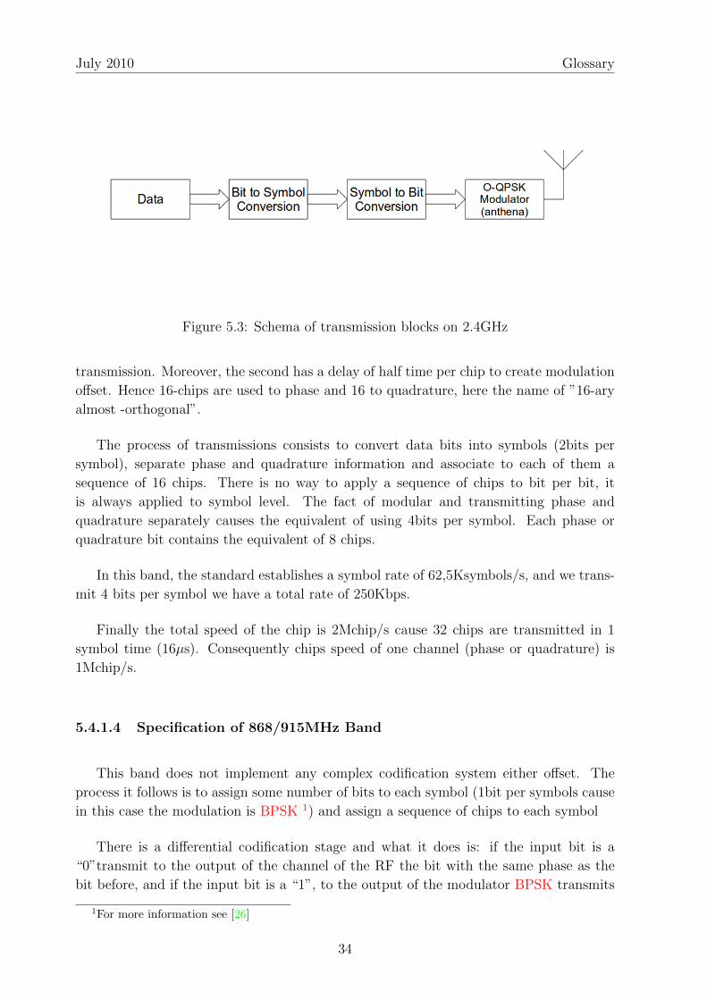
Figure 5.3: Schema of transmission blocks on 2.4GHz
transmission. Moreover, the second has a delay of half time per chip to create modulation
offset. Hence 16-chips are used to phase and 16 to quadrature, here the name of ”16-ary
almost -orthogonal”.
The process of transmissions consists to convert data bits into symbols (2bits per
symbol), separate phase and quadrature information and associate to each of them a
sequence of 16 chips. There is no way to apply a sequence of chips to bit per bit, it
is always applied to symbol level. The fact of modular and transmitting phase and
quadrature separately causes the equivalent of using 4bits per symbol. Each phase or
quadrature bit contains the equivalent of 8 chips.
In this band, the standard establishes a symbol rate of 62,5Ksymbols/s, and we trans-
mit 4 bits per symbol we have a total rate of 250Kbps.
Finally the total speed of the chip is 2Mchip/s cause 32 chips are transmitted in 1
symbol time (16µs). Consequently chips speed of one channel (phase or quadrature) is
1Mchip/s.
5.4.1.4 Specification of 868/915MHz Band
This band does not implement any complex codification system either offset. The
process it follows is to assign some number of bits to each symbol (1bit per symbols cause
in this case the modulation is BPSK 1) and assign a sequence of chips to each symbol
There is a differential codification stage and what it does is: if the input bit is a
“0”transmit to the output of the channel of the RF the bit with the same phase as the
bit before, and if the input bit is a “1”, to the output of the modulator BPSK transmits
1For more information see [26]
34

Modular Home Automation Systems For Senior Citizens Quing-Wen He Chen
Figure 5.4: Schema of transmission blocks on 868/915 MHz Band
Band Numberof Ch.
Bit Rate Symbol Rate Modulation Chip Speed
868-868.6MHz
1 20 Kb/s 20 Ksymb/s BPSK 300 Kchip/s
902-928MHz
10 40 Kb/s 40 Ksymb/s BPSK 600 Kchip/s
2.4-2.4835MHz
16 250 Kb/s 62.5 Ksymb/s O-QPSK 2 Mchip/s
Table 5.12: Relation between bit rate, symbols and chip speed in each band
the actual bit in contra phase regarding the one before.
For a side the symbol to chip conversion is done to code reversion, i.e a code of 15
chips is transmitted for “1”and the reverse code is transmitted when is a “0”.
5.4.1.5 Spectral Duty Bands and Channel Assignation
IEEE 802.15.4 requires devices to work in 2 spectral bands. The first case (868 and
915 MHz) contains 2 sub-bands so they have to work (getting more compatibility in the
market without increase excessively the price of the final product because both bands are
close to each other). The second case is the band of 2.4GHz.
The table 5.12 shows the relation among bands, the number of channels of the band
and transmission speed of each one.
The decision to choose one band or another depends on the geographic localization
and the destined market of the applications cause those mentioned bands are not free in
all the countries. In the table 5.13 shows channel assignation depending on the band and
regional availability.
35

July 2010 Glossary
Band Channel CentralFrequency(MHz)
Regional Availabil-ity
Additional Limita-tions
868 MHz 0 868.3 Only available in greatpart of Europe
No power limitation.The transmission’sduty cycle have to belower than 1%
915 MHz
1 906
This band has freechannels in NorthAmerica, NewZeland, Australia andsome countries ofSouth America
Despite somegovernments canimpose somerestrictions, in generalis not limited eitherin duty cycle either inpower transmission
2 9083 9104 9125 9146 9167 9188 9209 92210 924
2.4 GHz
11 2405
This band is free ingreat part of theworld
No limitation eitherin transmission powereither in duty cycle inany geographic zone.
12 241013 241514 242015 242516 243017 243518 244019 244520 245021 245522 246023 246524 247025 247526 2480
Table 5.13: Channels per transmission band
36

Modular Home Automation Systems For Senior Citizens Quing-Wen He Chen
5.4.1.6 Power Transmission and Receivers Sensibility
The minimum sensibility required by the receptor changes depending on the duty
band, though both bands have a small limitations, essentially we need low input signal
to work properly. This guarantees the receptor do not have to be anything complicated,
reducing the fabrication cost. The table 5.14 shows the sensibility depending on the
spectral band.
IEEE 802.15.4 standard do not establish any maximum power transmission, in fact you
can use any power transmission. However it establishes the minimum power transmission
in -3 dBm to achieve reasonable transmission distances.
Band Sensibility868/815 MHz -92dBm
2.4 GHz -85dBm
Table 5.14: Relation between needed sensibility of the receiver per each band
5.4.1.7 Selectivity of the Receiver
Because we are using a DSSS system, we do not require a high selectivity. Moreover,
IEEE 802.15.4 standard channels are very spaced among themselves (5MHz in 2.4GHz
band) compared to their bandwidth (3MHz).
5.4.1.8 Channel Selectivity and Adjacent Channel Blocking
IEEE 802.15.4 establishes a minimum rejection of the adjacent band due to a correct
work of the system. On the 868MHz band there is nothing defined cause there is only
one channel. For 915MHz and 2.5GHz band established that the receiver system have to
reject a adjacent channel of the same power level as the useful one.
On the other hand it also establishes that the system can reject those secondary
interference channels (those with 2 channels separation from the useful one) till 30dB
more powerful than the power of the useful transmission.
In the end the standard also establishes the maximum input signal power of the re-
ceptor have to be -20dBm to work without saturation problems either increase of errors
rate.
37

July 2010 Glossary
5.4.1.9 Channel Access
Channel Access is managed in MAC layer, anyway the chosen access determines the
physic layer cause this one has to implement a lot of features to let MAC manage the
channel access. That is why we comment it in this layer.
Medium Access in ZigBee is independent to the type of the network or used topology,
it only depends if it transmits using the mode with signal frames (superframe) activated
or not. If not we will access to the medium using CSMA-CA type of access. If yes we will
use GTS to transmit in case we have a reserved time slot, if we have not reserved time
slot to transmit we will use CSMA-CA
5.4.2 Structure of physic layers packages
The physic layer has a defined structure for each package (PPDU). Upper layers frames
are resumed in upper layers frames and, therefore, the PPDU is the last encapsulation
before channel access and transmit.
PPDU SynchronismHeader (40 bits)
PPDU Header (8 bits) PPDU body (0 - 128 Bytes)
Table 5.15: Generic structure of Physic Layer’s data services frames
The table 5.15 shows the structure of the packages which has 3 parts:
PPDU’s Synchronization Header (40 bits)
The PPDU’s Synchronization Header is independent from the duty band and has 2
basic fields:
• A preamble of 32 logic zeros to let the receiver to synchronize correctly with
the sender (remember that those zeros are grouped in symbols and are coded
using a sequence of chips, therefore they will not be real transmitted zeros)
• A field to define the begin of the frame and consists in a determined sequence
of 8 bits (”11100101” in binary) to let the receiver to establish the begin of the
package.
PPDU’s Header (1 Byte)
Is a 8 bits header where the highest bit is reserved and the last 7 are destined
to advise the length of the package (the maximum length is 128Bytes). Packages
between 0 and 4 Bytes and 6 and 7 Bytes are reserved. Packages of 5 Bytes are
ACK which contains a ACK’s MAC. Packages of 9 or more Bytes are packages with
38

Modular Home Automation Systems For Senior Citizens Quing-Wen He Chen
useful data for physical upper layers. The information referred to ACK’s MAC have
be seen in
PPDU body (0-128 Bytes)
Is a unique fiend composed by the Physical Layer Service Data Unit (PSDU). It can
vary among 0 and 128 Bytes and contains all the useful data of the PPDU, namely
data for upper layers.
5.4.3 Physic Layers Services
Physic Layer’s services are a set of minimum needed primitives that the physic layer
offers to MAC layer.
The difference between primitives and packages may be noticed. Primitives are the set
of minimum functionalities which each layer has to offer to upper layers and therefore, are
originated in each device. On the other hand, packages refer to external transmissions,
that is, among devices. Although primitives might cause a packet to transfer, and a
received packet launches a set of primitives, they are not the same.
Basically, physic layer offers two services: Physical Data (PD) Service and Physical
Layer Management Entity (PLME) Service.
There is a total of 4 types of subfunctions what a primitive can do:
Request: This primitive comes from upper layers to request the initiate the service.
Indication: This primitive goes from the physic layer to its immediately upper layer to
notify important succeeded events in the physic layer. Those notifications can be
caused by an internal event from the physic layer o cause the reception of a frame
from another device.
Response: This primitive is originated in upper layers to physic layer and it’s send to
answer to some request primitive originated in the physic layer.
Confirm: Goes from the Physic layer to upper layers to answer some previous request
primitive.
5.4.3.1 Data Service in the Physic Layer
Physic Layer’s Data Service (referenced as PD-DATA) manages all data requests to
the physic layer, from upper layers or from the network. Offers to MAC a unique primitive
with 3 subfunctionalities: request, confirm and indication.
39

July 2010 Glossary
Figure 5.5: Example using physic layer’s data service’s primitives
Physic Layer also disposes of Management services but we are not entering in this
field.
5.5 ZigBee – Bluetooth – Wi-Fi Comparative
There are a lot of wireless alternatives for designers. We will compare ZigBee with
other popular standards who are also sharing unlicensed 2.4GHz band. You can see it in
the table 5.16.
ZigBee Bluetooth Wi-Fi(Wireless LocalArea Network(WLAN))
(WLAN/WPAN) (WPAN)
MAC Standard 802.15.4 802.15.1 802.11MaximumTransmissionRate
250kbps 1Mbps Till 54Mbps
TransmissionConsumption
35 mA 40 mA >400 mA
Standby 3µA 200µA 20mAMemoryrequirement
32-60KB >100KB >100 KB
NetworkConnection Options
Mesh, point to pointor point to multipoint
point to point point to multi-point
Table 5.16: ZigBee –Bluetooth –Wi-Fi Comparative
40

Modular Home Automation Systems For Senior Citizens Quing-Wen He Chen
5.5.1 Why not choose Bluetooth or Wi-Fi?
Bluetooth is a very popular wireless communication system based in the standard
IEEE 802.15.1. Bluetooth works with a data transmission rate of 1Mbps. Bluetooth and
ZigBee have similar power transmission, but ZigBee has a better resource, its low power
in standby mode. This is because devices in Bluetooth networks have to send information
to the network frequently to keep the synchronization so they can switch easily to sleep.
Wi-Fi is a network which requires almost uninterrupted activity of its devices. The
advantage of this standard is the great amount of information you can send from one
point to multi-point but you can see that the transmission power is also high.
From those 3 standards, only ZigBee offers the flexibility of mesh networks. ZigBee
applications typically are very simple, that is why its memory requirements are also very
low compared to the other two.
5.5.2 PAN: ZigBee vs Bluetooth
Carefully looking the comparative of those two standards, both of them are in the
PAN category, both of them have similar radios but they are not similar at all in energy
consumption. The main difference between those two standards is in its application field.
Bluetooth aims to applications with a average data transfer and uninterrupted service
such as file transfer and sound transmission in communications.
ZigBee aims to applications with low data rate and low cycles of service. Devices end
point do not transfer or receive information so frequently in this kind of applications and
allows increase the duration of the battery.
However we can say that they are not competitive technologies yet complementary
since they are two different solutions for different application fields.
We can add that Bluetooth connections among Bluetooth devices are not as flexible
as ZigBee, the link is strong and static versus the flexibility of ZigBee.
41

July 2010 Glossary
Figure 5.6: ZigBee versus Bluetooth
42

Chapter 6
Modular Software and Wireless
Devices Organization
6.1 Introduction
Software Engineering has advanced a lot in the last years. Introducing Software En-
gineering in programming permitted to advance to modular software.
Modular software permits to do isolated changes and introduces code reusability. Mod-
ular software also increases security, making software maintenance easy.
Some of Software characteristics are:
• Is developed, not produced
• It never spoils
• Software maintenance is more difficult than Hardware.
Software Engineering introduces the following ideas:
• Economic
• Reliable
• Efficient work
• To satisfy users requirements
43

July 2010 Glossary
6.2 Proposed system Schema
The figure 6.1 shows a general and simplified idea of the system. There are 2 types of
users, a part of the HAS there is a ZigBee Network. We will see the details of each one
separately.
Users can read information and change the configuration of the system. There are 2
kinds of information: Real Time Information and Stored Information. On the first one,
when the users asks to the HAS the information, this sends a request to affected nodes
as you can see in the figure 6.2. In the second case, is very similar but the HAS instead
to send the request to the ZigBee Network, just checks the Data Base (DB).
The figure 6.3 shows the flow of the information in the ZigBee network. Basically how
collected data travels from the Sensors to the HAS and this sends orders to the actuators.
The information goes from bottom to top and after that goes down again.
6.3 Technical Architecture
In this part we will define the technical system and how it works.
6.3.1 Programation
The chosen environment to implement the HAS program is Java 2 Enterprise Edition.
Java is a Object Oriented Programming Language, perfect for high level programming.
Those properties are not exclusive of Java Platform. The main reason is because Java is
very portable and architecture independent.
Java has some strong points like:
Object-Oriented Paradigm
Garbage Collection: No more stray pointers problems.
Class loading: You can dynamically deploy more code after your device has been de-
ployed.
Robust Security Architecture: You can deploy fine-grained security control if you
want. No need to re-invent your own, and risk inventing one that has security holes.
Networking: Standard Application Programming Interfaces (APIs) allow you to do net-
working easy.
44

Modular Home Automation Systems For Senior Citizens Quing-Wen He Chen
Figure 6.1: General Schema of the structure of the proposed Home Automation System
45

July 2010 Glossary
Figure 6.2: Order Flow Schema
Figure 6.3: Data Flow Schema
46

Modular Home Automation Systems For Senior Citizens Quing-Wen He Chen
6.3.2 Data Base
At first sign we don’t need a high performance DB and all needed functionalities are
basic like store and load data, creating tables and databases. Also we want to reduce
economic costs so we can use MySQL1 as our DB Software Management.
6.3.3 Operating System
Cause we chose Java as our programming language, we do not have to worry about
the Operating System (OS), we have an OS independent program. Java uses a Virtual
Machine called Java Virtual Machine (JVM) which uncouples the portability problem
among OS. Every OS who can run the JVM will be able to run our program.
6.4 Proposed Basic Program
To fulfill our proposed target we will apply GRASP guidelines. GRASP is a set of
patterns to answer some software problems. GRASP is a mental toolset, a learning aid
to help in the design of object oriented software. Some of the main GRASP patterns are:
Expert: Information Expert is a principle used to determine where to delegate respon-
sibilities. These responsibilities include methods, computed fields and so on.
Using the principle of Information Expert a general approach to assigning respon-
sibilities is to look at a given responsibility, determine the information needed to
fulfill it, and to determine where that information is stored.
Information Expert will lead to placing the responsibility on the class with the most
information require to fulfill it.
Creator: Creation of objects in one of the most common activities in object-oriented
systems. Which class is responsible for creating objects is a fundamental property
of the relationship between objects of particular classes.
In general, a Class B should be responsible for creating instances of class A if one
or more following rules can be applied:
• Instances of B “contains or compositely aggregates”instances of A.
• Instances of B records instances of A.
• Instances of B close uses instances of A.
1http://www.mysql.com
47

July 2010 Glossary
• Instances of B have the initializing information for instances of A and pass it
on creation.
Controller: The Controller patter assigns the responsibility of dealing with system
events to a non-User Interface class that represent the overall system or a use case
scenario. A Controller Object is a non-user interface object responsible for receiving
on handling a system event.
A use case controller should be used to deal with all system events of a use case,
and may be used for more than one use case
It is defined as the first object beyond the User Interface layer that receives and
coordinates (“Controls ”) a system operation. The controller should delegate to
other objects the work that needs to be done; it coordinates or controls the activity.
It should not do much work itself.
Low coupling: is an evaluative pattern, which dictates how to assign responsibilities to
support:
• Low dependency between classes
• Low impact in a class by changes in other classes
• High reuse potential
High Cohesion: Is an evaluative pattern that attempts to keep objects appropriately fo-
cused, manageable and understandable. High Cohesion is generally used to support
Low Coupling. High Cohesion means that the responsibilities of a given element
are strongly related and highly focused. Breaking programs into classes and subsys-
tems is an example of activities that increase the cohesive properties of a system.
Alternatively, low cohesion is a situation which a given element has too many un-
related responsibilities. Elements with low cohesion often suffer from being hard to
comprehend, hard to reuse, hard to maintain and adverse to change.
Indirection: Supports low coupling between two elements by assigning the responsibility
of mediation between them to and intermediate object. An example of this is the
introduction of a controller component for mediation between data (model) and its
representation (view) in the Model-View-Controller pattern.
We want to propose a modular HAS program. To achieve this goal, we propose a
basic system. To build our basic system, we suggest using some design patterns to keep
the system’s modularity:
Model View Controller (MVC): Widely used in Internet platforms like websites. It
divides the presentation Layer into 2 parts: Controller and View. The Controller
receives the petition from the user and sends it to the Model. The Model processes
the information and sends the answer to the View. The user can see the answer of
the system through the View. Model is the equivalent of the Domain Layer of 3
48

Modular Home Automation Systems For Senior Citizens Quing-Wen He Chen
Layers but in this case can be only one part of it. The Controller is the same as the
one described before 6.4.
3 Layers: It divides the whole system in 3 layers: Presentation, Domain and Data. The
Presentation Layer interacts with the user, sends the petition to the Domain. The
Domain Layer computes the data and if have to store or load data, it asks to Data
Layer. After the computations resends the information to the Presentation Layer
and this one to the user. Each Layer is independent so you can modify each one per
separate and the system can continue working normally. It is transparent, secure
and maintainable.
Transaction: Capsules the functions in a set of listed actions. Every time you invoque
an action, you are executing a transaction. It permits to increase the security and
introduces atomicity in those. If you execute a transaction, if you can not execute the
whole listed actions it will not change the system and make the petition persistent.
It is really useful when the system fails or there are interferences.
Chain of responsibility: Is a pattern to help low Coupling. You should delegate the
responsibility to do some action to the module that is closer to the one who really
knows how to do it.
Facade: Provides a Unified interface to a set of interfaces in a subsystem. Fa?ade defines
a high-level interface making the subsystem easy to use.
Iterator: Provides a way to access the elements of an aggregate object sequentially with-
out exposing its underlying representation.
Observer: Defines a one-to-many dependency between objects so that when one object
changes state, all its dependents are notified and updated automatically.
State: Allows an object to alter its behavior when its internal state changes. The object
will appear to change it class.
Strategy: Defines a family of algorithms, encapsulate each one, and make them inter-
changeable. Strategy lets the algorithm vary independently from clients that use
it.
We have to take into account that the interface for aged people should be as easy
and intuitive as it can be. To get more information you can check Interface Design for
Domotic Applications in [30]
6.5 Functions
In this section we will introduce some basic functionalities of the main program due
to achieve our expandable system.
49

July 2010 Glossary
6.5.1 Application Management
The system can distinguish between two type of different additions: applications and
modules. Modules are destined to extend the system adding new capabilities and Appli-
cations are other programs that can interact with our system. Also modules can only
work under the petition of our system and applications are autonomous, independent of
our system but with the possibility of interaction.
The system have also its own configuration, independent of each module or application,
which lets the user change the behavior of the main system such as sampling periodically,
periodically saving data, where each de device belongs to, change the privileges of users
or adding new users.
Also our needs can change so the program can also permit the option to delete installed
applications and modules. Other times we just do not theed their functionality so just
need to enable or disable them.
6.5.2 Data Base Management
In a first sign, we decided that it would be interesting to have a Data Base for each
module, independently. This is because we want to keep low cohesion and each module is
free to organize its tables on its own but keeping a basic structure similar to all modules.
In the case of applications, due to they are independent from our system, we can just
store basic information like where it is, its name, its description. So we just store a pointer
to its localization, not concerning about its internal architecture or organization.
The main system will have a Data Base with different tables to save information about
Users and their privileges, installed modules (name, functionalities, with data base is, etc),
installed applications (Application name, where it is and a brief description if needed),
the state of the system, registered devices (to which cluster belongs, their MAC address,
function, etc). There is a table for installed applications and another for modules to let
the system know what it has and where they are.
6.5.3 Web Service
Our system can be accessed through Internet by remote users. Due to keep the safety
of our system, we will use a web server with a Content Management System (CMS).
50

Modular Home Automation Systems For Senior Citizens Quing-Wen He Chen
There are a lot of modular CMS such as Joomla2 or Drupal3 among others, with basic
functionalities and letting to the user to choose which functionalities are needed.
6.6 Users
As mentioned before, there are 2 types of users:
Local Users
Those users can connect to the HAS directly through the Local Area Network
(LAN).
Remote Users
Those users can connect to the HAS using Internet access. In general their func-
tions are limited compared to local users, basically their main operations are read
operations. Even in Remote Users, there are different kinds: Those who can only
read and those who can modify the configuration. Basically depends on the func-
tionality. Those who can only read are external services and those who can modify
are relatives of the user.
6.7 ZigBee Network
ZigBee specification have been widely explained in the chapter 5. After all the expla-
nation, the most important is how to organize the devices network. ZigBee offers 3 types
of Topology: Star topology in this case is almost useless in case of big surfaces because
consumed energy increases exponentially in far devices. Mesh topology can be deployed
in this kind of scenario and tree topology can also be deployed.
6.7.1 Topology
Depending on the topology, the organization of the network can be easy or difficult;
also energy consumption can change a lot.
We decided to use a Cluster Tree Topology. This topology is equivalent to the native
ZigBee’s Tree Topology with clusters and each device belongs to a only one cluster.
2http://www.joomla.org3http://www.drupal.org
51

July 2010 Glossary
There is a Network Coordinator (our HAS), some Cluster Heads (FFD devices) and
Routers (FFD devices) and Terminal Nodes (RFD devices).
The number of Cluster Heads depends on how many clusters we want to have. Here
we found a big problem. What is better? Making different clusters depending of the
kind of devices such as a cluster for light sensors, one for temperature sensors, one for
switch actuators... or mixing each one and in result, having heterogeneous clusters? We
prioritized the energy consumption instead of simply network management and we decided
that heterogeneous clusters are preferred.
In Tree Topology, the information flows from bottom to top and the orders goes from
top to bottom. The cost in time is Θ(log n) where n is the number of devices. We arrived
to this conclusion following the next reasoning.
1. We will consider the total number of devices as
n
2. We will consider the transmission time of each device as
delayi, 0 ≤ i ≤ n
3. In a lineal topology, to go from the first node to the last one will cost
Θ(∑n
i=1 delayi)
4. The first think we need to know about trees is that their height is
Θ(log n)
5. We can define delaymax as the time of the slowest device, simplify the formula of 3 as
O(n× delaymax) =∑n
i=1 delayi
6. We can adapt the time to tree topology and we will have
Θ(log(n× delaymax))
52

Modular Home Automation Systems For Senior Citizens Quing-Wen He Chen
Figure 6.4: Example of Cluster Tree Topology where the black square is the NetworkCoordinator and the first level of squares are cluster heads and under those there arerouter and terminal nodes
7. For huge values of n despise the value of delay (also because is a constant). That
is why we can conclude as
Θ(log(n))
To implement this topology we can use implementation proposals such those mentioned
in [22], [23] or [24].
6.7.2 justification of the decisions
The reason to choose ZigBee is obviously because it fulfills our requirements and it is
cheap.
We have chosen clustered-tree cause it is easy to implement, easy to manage and the
53

July 2010 Glossary
consumption is lower than mesh topologies. The energy efficiency and other advantages
are widely explained in [13]
The path took by a message in Cluster Tree topology would be longer than a Mesh
Topology or Star Topology but the cost of maintenance is much lower and due to the low
rate network, and the complexity of network management is also lower.
54

Chapter 7
Conclusion
The populations gradually aging problem is something we can not solve but we can
help to make it more comfortable. There are also many on-going research such as [31],
[32] or [33] as well as active projects such as Mercury [28] that can be used for introducing
aging people to wearable sensors.
Home Automation Systems are more and more popular making people’s life easier
but it is still very limited in functionalities. There are HAS projects like Casas[27] which
collects data to make a big DB to achieve a Expert System[37].
There are a lot of similar works making this research field a hot spot. Looking for low
cost Home Automation Devices such as mentioned in [14]
We can conclude that there is an effort to make HAS something common and affordable
just like computers and television progressed over the centuries.
To make a robust HAS software still requires a lot of work and it can not be done by
few people. The same way that modular software is made to big companies to do different
tasks can be applied in this platform.
On Wireless Devices, technology is advancing in lighting speed and it is not difficult
to say that in the future they will be smaller, faster with low energy consumption but
without a good management system it is completely useless. In this case, a Tree-type
topology is the best choice but in other fields like multimedia a peer-to-peer topology
would be more efficient and will offer better QoS.
Future work related with this thesis may be a real implementation of a modular HAS
using patterns described in 6.4
55

July 2010 Glossary
56

Appendix A
A Brief Explanation of DSSS
Direct Sequence Spread Spectrum (DSSS) is a transmission mode where the transmit-
ted signal deals with a wider bandwidth than really needed. Due to achieve this spectrum
expansion, an independent code sequence of the information signal is used.
The idea is to transmit all the sequence of the code in the same time we use to
transmit a bit of information. If the bit of information was a logic “1”a sequence of code
without changes will be transmitted, if it is a logic ‘’0”a reverse sequence of code will be
transmitted. In resume, we can affirm that it is a XOR operation between the information
and the code synchronized to the speed of the code.
The fact to transmit a whole sequence of bits in the time of one only bit provokes a
spectral expansion. Some examples are show in figure A.1 and figure A.2
A Tc (Chip Time) is defined as the needed time to transmit a bit of code. Then,
Ts = N × Tc and N-chips are transmitted per symbol. Have to take into account that N
is a natural number.
One of the main features of this transmission mode is that each user has a unique
code that is orthogonal with all other codes. Because the number of orthogonal codes
among each other is limited, pseudo-random codes are used such as Gold,Barker, Sequence
M, etc. which can guarantee the code orthogonality in a high percent, achieving a high
number of available orthogonal codes (and increase the number of users) keeping a correct
duty of the system
Those codes are used because in case of 2 users transmits at the same time, the
receiver will receive the addition of both transmissions. Due to undo the expansion the
orthogonality is needed.
To decode, the receiver multiplies the received sequence with the code of one of the
57

July 2010 Glossary
Figure A.1: First example of sequence of chips
Figure A.2: Second example of sequence of chips
58

Modular Home Automation Systems For Senior Citizens Quing-Wen He Chen
Figure A.3: Spectrum comparation
nodes, chip by chip with each active user. The result is integrate all received chips . . . (in
other words, add all received chips) and the result will be the sequence of bits of the
original information.
Obviously the system requires a perfect temporal synchronization between sender and
receiver, in addition also requires a perfect power control because in case of multiple-
senders, the receiver will receive the addition of both codes.
Spectrally, once expanded, the spectrum is so wide and the power is distributed in so
many frequencies that a signal without expansion would be just noise.
In conclusion, the advantages to use this system are the high interference protection
that offers and the fact that several users can share the same frequency band and can
transmit at the same time (without dividing the spectrum either temporal access). On
the other hand, the strict synchronism and the power control are needed, also the fact
that a wider band is needed
59

July 2010 Glossary
60

Bibliography
Wireless Standards and Basis:
[1] I.F. Akyildiz, W. Su, Y. Sankarasubramaniam and E. Cayirci . Wireless sensor net-
works: a survey Computer Networks(Elsevier) Journal, Vol. 38, No. 4, pp. 393-
422. March 2002 <http://www.ece.gatech.edu/research/labs/bwn/surveys/
sensornets.pdf> [October 2009]
[2] IEEE Standard 802.15.4. 2003 <http://standards.ieee.org/getieee802/
download/802.15.4-2003.pdf> [March 2010]
[3] ZigBee Alliance. <http://www.zigbee.org/en/index.asp> [March 2010]
[4] F. L. Lewis Wireless Sensor Networks Smart Environments: Technologies, Protocols,
and Applications . 2004 [March 2010]
ZigBee Specification and Features:
[5] ZigBeee AllianceZigBee Specification. <http://www.zigbee.org/en/spec_
download/download_request.asp> [March 2010]
[6] Maxim An Introduction to Direct-Sequence Spread-Spectrum Communications, 1890
Application Note. <http://www.maxim-ic.com/appnotes.cfm/appnotet_number/
1890> [April 2010]
Direct Sequence Spread Spectrum:
[7] ICT Technologies Wireless Communications Spread Spectrum Systems. Chapter
8, module 7, page 74. <http://cbdd.wsu.edu/kewlcontent/cdoutput/TR502/
page74.htm> [April 2010]
[8] William C. Craig ZigBee: Wireless Control that Simply Works. ZMD
America. <http://plato.csie.ncku.edu.tw/Network-slides-dir/
ZigBeeWireless-Craig.pdf> [March 2010]
61

July 2010 Glossary
[9] Patrick Kinney ZigBee Technology: Wireless Control that Simply Works. <http:
//www.zigbee.org/imwp/idms/popups/pop_download.asp?contentID=5162>
[March 2010]
Senior Citizen Information:
[10] CDC Report. Today’s Senior Citizen Turning Age 65 Can Now Expect to Live to
Almost 84 . August, 20 th 2009. <http://seniorjournal.com/NEWS/SeniorStats/
2009/20090820-TodaysSenCitizen.htm> [June 2010]
Home Automation Systems:
[11] Caio Augustus Morais Bolzani, Cristian Montagnoli and Marcio Lobo Netto . Do-
motics Over IEEE 802.15.4 - A Spread Spectrum Home Automation Application .
IEEE Ninth International Symposium on Spread Spectrum Techniques and Appli-
cations, 2006 <http://ieeexplore.ieee.org/stamp/stamp.jsp?tp=&arnumber=
4100591> [March 2010]
[12] Khusvinder Gill, Shuang-Hua Yang, Fang Yao and Xin Lu A ZigBee-Based Home
Automation System . IEEE Transactions on Consumer Electronics, Vol. 55, No.
2 . May 2009 <http://ieeexplore.ieee.org/stamp/stamp.jsp?tp=&arnumber=
5174403> [March 2010]
[13] Saad Ahmad Khan, Fahad Ahmad Khan, Arslan Shahid, Zubair Ahmad Khan Zigbee
Based Reconfigurable Clustered Home Area Network Third International Conference
on Sensor Technologies and Applications . 2009 <http://ieeexplore.ieee.org/
stamp/stamp.jsp?tp=&arnumber=5210966> [March 2010]
[14] Juing-Huei Su, Chyi-Shyong Lee and Wei-Chen Wu . The Design and Implementation
of a Low-Cost and Programmable Home Automation Module . IEEE Transactions on
Consumer Electronics, Vol. 52, No. 4. November 2006 <http://ieeexplore.ieee.
org/stamp/stamp.jsp?tp=&arnumber=4050050> [April 2010]
[15] Michal Varchola and Milos DRUTAROVSKY . ZigBee Based Home Automation
Wireless Sensor Network . Acta Electrotechnica et Informatica No. 4, Vol. 7, 2007
[April 2010]
Software Engineering:
[16] Design Patter <http://en.wikipedia.org/wiki/Design_pattern_(computer_
science)> [June 2010]
[17] GRASP (object-oriented design) <http://en.wikipedia.org/wiki/GRASP_
(object-oriented_design)> [June 2010]
62

Modular Home Automation Systems For Senior Citizens Quing-Wen He Chen
[18] Craig Larman . Applying UML and Patterns (3rd ed.) 2005. <http://authors.
phptr.com/larman/uml_ooad/index.html> [June 2010]
[19] Dolors Costal, M. Ribera Sancho and Ernest Teniente . Enginyeria del Software
Especificacio: Especificacio de Sistemes Orientats a Objectes amb notacio UML .
Edicions UPC February 2000 . [April 2010]
[20] Cristina Gomez, Enric Mayol, Antoni Olive and Ernest Teniente . Enginyeria del
Software Disseny I: Disseny de Sistemes Orientats a Objectes amb notacio UML .
Edicions UPC February 2001 . [May 2010]
[21] Carles Farre, Antoni Olive and Carme Quer . Enginyeria del Software Disseny II:
Disseny orientat a Objectes de sistemes distribuıts sobre CORBA . Edicions UPC
September 2000 . [May 2010]
Cluster Tree:
[22] S. John Peter, S. P. Victor . A Novel Algorith for Minimum Spanning Clustering
Tree . Journal of Theoretical and Applied Information Technology 2010 JATIT .
<http://www.www.jatit.org> [May 2010]
[23] H. M. N. Dilum Bandara, Anura P. Jayasumana . An Enhanced Top-Down Cluster
and Cluster Tree Formation Algorithm for Wireless Sensor Networks . [May 2010]
[24] Bhaskaran Raman Lecture 23: Routing Layer in ZigBee . 29 th September 2005 .
[May 2010]
Signal Modulation:
[25] Binary Phase Shift Keying (BPSK) <http://en.wikipedia.org/wiki/
Phase-shift_keying#Binary_phase-shift_keying_.28BPSK.29> [June 2010]
[26] Offset Quadrature Phase-Shift Keying (O-QPSK) <http://en.wikipedia.org/
wiki/Phase-shift_keying#Offset_QPSK_.28OQPSK.29> [June 2010]
Related Work:
[27] Washington State University . Project Casas <http://ailab.wsu.edu/casas/>
[March 2010]
[28] University of Harvard . Mercury Project <http://fiji.eecs.harvard.edu/
Mercury> [March 2010]
[29] Yoosoo Oh, Jonghyun Han and Woontack Woo . A Context Management Ar-
chitecture for Large-Scale Smart Environments. IEEE Communications Magazine
, March 2010. <http://ieeexplore.ieee.org/stamp/stamp.jsp?tp=&arnumber=
5434383> [June 2010]
63

July 2010 Glossary
[30] Juan Jose Sanchez Perez Disseny D’interfıcies grafiques per Aplicacions a
la Domotica . Treabll Fi de Carrera Enginyeria Tecnica Industrial Especial-
itat Electronica Industrial . February 2008 . <http://upcommons.upc.edu/
pfc/bitstream/2099.1/4848/1/Disseny%20d%27inerf%c3%adcies%20gr%c3%
a0fiques%20per%20aplicacions%20a%20la%20dom%c3%b2tica.pdf> [May 2010]
[31] Juan P. Garcia-Vazquez, Marcela D. Rodriguez and Angel G. Andrade . Ambient
Information Systems for Supporting Elder’s Independent Living at Home . IWANN
2009, Part II, LNCS 5518, pp. 701–704, 2009 [March 2010]
[32] Juan Pablo Garcıa-Vazquez and Marcela D. Rodrıguez . Ambient Information Sys-
tems to Support the Elderly in Carrying out their Activities of Daily Living . [March
2010]
[33] Juan P. Garcıa-Vazquez, Marcela D. Rodrıguez, Angel G. Andrade, Diana Saldana,
Fabian Mercado, Emanuelle Ruelas . Ambient Information Systems for Supporting
Ageing in Place [March 2010]
LATEXDocumentation:
[34] LATEX <http://en.wikibooks.org/wiki/LaTeX> [June 2010]
[35] LATEXMatters <http://texblog.wordpress.com> [July 2010]
[36] Scott Pakin The Comprehensive LATEXSymbol list . 2nd July of 2001 [July 2010]
Other Information
[37] Expert system . <http://en.wikipedia.org/wiki/Expert_System> [July 2010]
64