MODULAR ELECTRICAL MACHINES corectat final -...
6
MODULAR ELECTRICAL MACHINES – A SURVEY BENŢIA Ioana, RUBA Mircea, SZABÓ Loránd Department of Electrical Machines, Technical University of Cluj-Napoca 400020 Cluj, Daicoviciu nr. 15, Romania; e-mail: [email protected] ABSTRACT Industrial systems are in a process of continuous expansion in means of increased safety and fault free operation. A way in achieving increased tolerance of electrical machines is to modularise them. This paper presents a synthesis of the existing modular motors. Starting with the definition of a modular motor a few models are described. It is shown that the advantages of the structures presented are very important for different applications. It will be also highlighted that construction of this machines is a little more complicated in comparison with the classical machines. The paper focuses on the special design and function of these motors. INTRODUCTION The concept of modular motor emerged in the field of machines technology because of the demand of safety and reliability of the applications. This concept appeared since 1977 in a patent named "Modular Motor" invented by C.R. Carlson Jr. and M.J. Hillyer [1]. This type of motors differs from the regular ones by their construction [2], [3]. In the paper three topologies are presented. The first motor to be described has modular stator and the second one a segmented rotor. The last motor selected for presentation is very interesting due to its electronic drive integrated in its structure. Transverse Flux Reluctance Motor (TFRM) The motor is a special reluctance motor with a transverse flux path that is free of expensive permanent magnets and has a cost-effective highly modular structure [4]. A segment of one phase of the transverse flux reluctance motor (TFRM) is shown in figure 1 [5]. The structure of the complete phase is represented in figure 2. The stator of the phase has a simple concentrated ring winding surrounded by equidistant salient poles [6]. Fig. 1. Segment of the TFRM [6]
Transcript of MODULAR ELECTRICAL MACHINES corectat final -...
MODULAR ELECTRICAL MACHINES – A SURVEY
BENŢIA Ioana, RUBA Mircea, SZABÓ Loránd
Department of Electrical Machines, Technical University of Cluj-Napoca 400020 Cluj, Daicoviciu nr. 15, Romania; e-mail: [email protected]
ABSTRACT
Industrial systems are in a process of continuous expansion in means of increased safety and fault free operation. A way in achieving increased tolerance of electrical machines is to modularise them. This paper presents a synthesis of the existing modular motors. Starting with the definition of a modular motor a few models are described. It is shown that the advantages of the structures presented are very important for different applications. It will be also highlighted that construction of this machines is a little more complicated in comparison with the classical machines. The paper focuses on the special design and function of these motors.
INTRODUCTION
The concept of modular motor emerged in the field of machines technology because of the demand of safety and reliability of the applications. This concept appeared since 1977 in a patent named "Modular Motor" invented by C.R. Carlson Jr. and M.J. Hillyer [1].
This type of motors differs from the regular ones by their construction [2], [3]. In the paper three topologies are presented. The first motor to be described has modular stator and the second one a segmented rotor. The last motor selected for presentation is very interesting due to its electronic drive integrated in its structure.
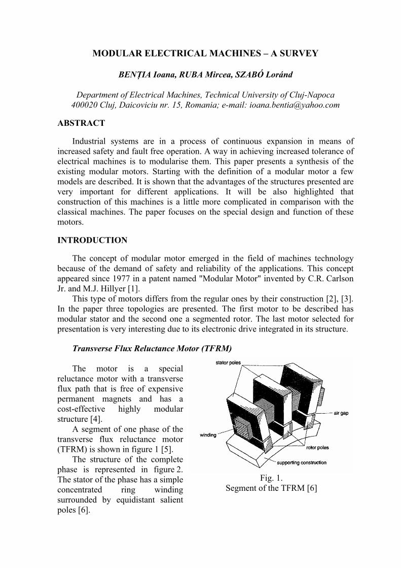
Transverse Flux Reluctance Motor (TFRM) The motor is a special
reluctance motor with a transverse flux path that is free of expensive permanent magnets and has a cost-effective highly modular structure [4].
A segment of one phase of the transverse flux reluctance motor (TFRM) is shown in figure 1 [5].
The structure of the complete phase is represented in figure 2. The stator of the phase has a simple concentrated ring winding surrounded by equidistant salient poles [6].
Fig. 1.
Segment of the TFRM [6]
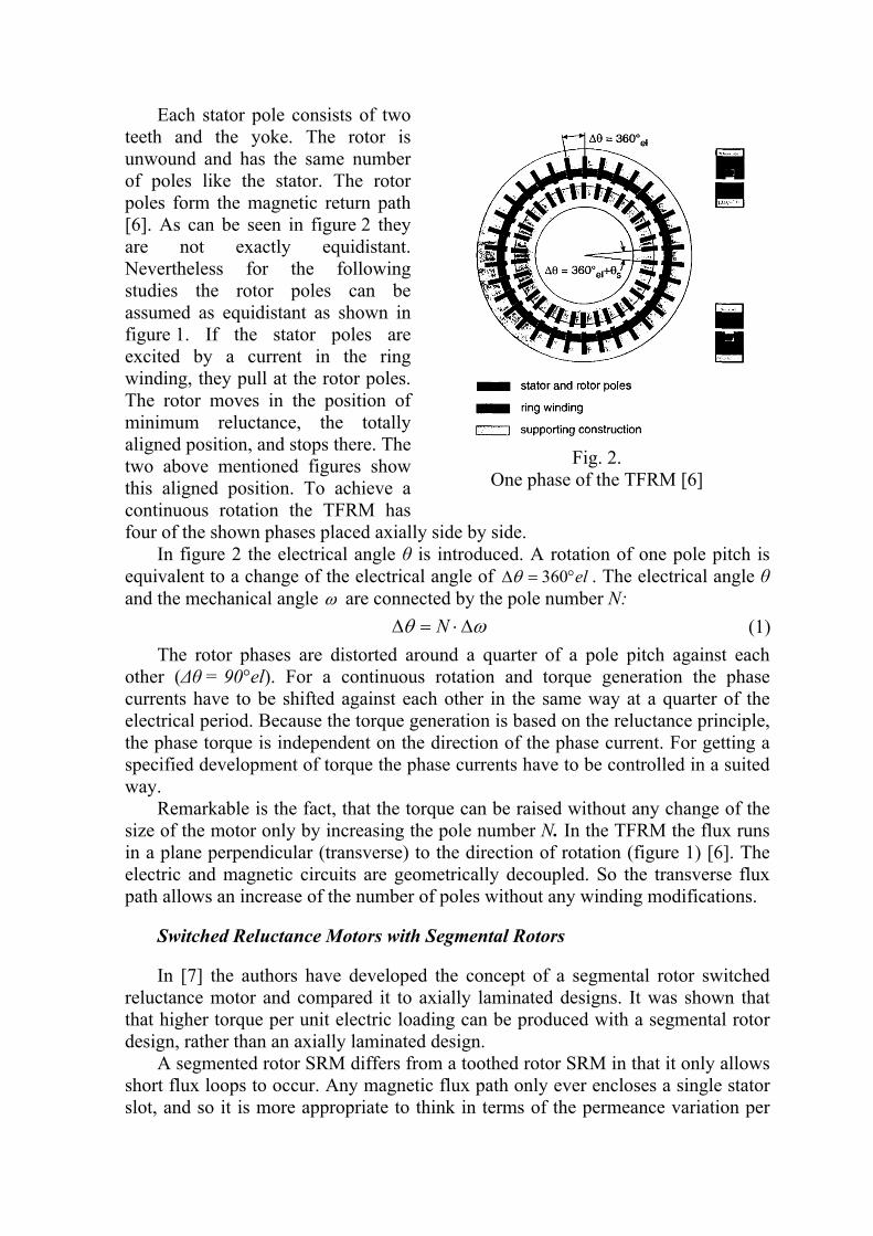
Each stator pole consists of two teeth and the yoke. The rotor is unwound and has the same number of poles like the stator. The rotor poles form the magnetic return path [6]. As can be seen in figure 2 they are not exactly equidistant. Nevertheless for the following studies the rotor poles can be assumed as equidistant as shown in figure 1. If the stator poles are excited by a current in the ring winding, they pull at the rotor poles. The rotor moves in the position of minimum reluctance, the totally aligned position, and stops there. The two above mentioned figures show this aligned position. To achieve a continuous rotation the TFRM has four of the shown phases placed axially side by side.
In figure 2 the electrical angle θ is introduced. A rotation of one pole pitch is equivalent to a change of the electrical angle of el°=Δ 360θ . The electrical angle θ and the mechanical angle ω are connected by the pole number N: ωθ Δ⋅=Δ N (1)
The rotor phases are distorted around a quarter of a pole pitch against each other (Δθ = 90°el). For a continuous rotation and torque generation the phase currents have to be shifted against each other in the same way at a quarter of the electrical period. Because the torque generation is based on the reluctance principle, the phase torque is independent on the direction of the phase current. For getting a specified development of torque the phase currents have to be controlled in a suited way.
Remarkable is the fact, that the torque can be raised without any change of the size of the motor only by increasing the pole number N. In the TFRM the flux runs in a plane perpendicular (transverse) to the direction of rotation (figure 1) [6]. The electric and magnetic circuits are geometrically decoupled. So the transverse flux path allows an increase of the number of poles without any winding modifications.
Switched Reluctance Motors with Segmental Rotors
In [7] the authors have developed the concept of a segmental rotor switched reluctance motor and compared it to axially laminated designs. It was shown that that higher torque per unit electric loading can be produced with a segmental rotor design, rather than an axially laminated design.
A segmented rotor SRM differs from a toothed rotor SRM in that it only allows short flux loops to occur. Any magnetic flux path only ever encloses a single stator slot, and so it is more appropriate to think in terms of the permeance variation per
Fig. 2.
One phase of the TFRM [6]
slot, rather than the permeance variation per tooth, which is evaluated in toothed SRMs.
Because the permeance variation per slot varies most strongly it was sensible to restrict the design so that a single slot only contains the windings of a single phase. By doing so the rate of change of phase self inductance with respect to position is maximised.
The most obvious approach to a three phase design which meets the above criteria is to employ fully pitched concentrated windings, resulting in a machine of the form illustrated in figure 3. The design bears a superficial resemblance to a synchronous reluctance motor. However, the machine is doubly salient, with semi-open stator slots and excited with unidirectional currents. It is therefore very much a switched reluctance, rather than a synchronous reluctance machine.
An immediate disadvantage apparent in the design is the long endwindings which result from fully pitched windings. Note that the machine illustrated in figure 3 is a 12-8 design: this is chosen in preference to a 6-4 design in order to reduce the endwinding length. All subsequent comparisons with a conventional toothed arrangement will include the endwinding effects.
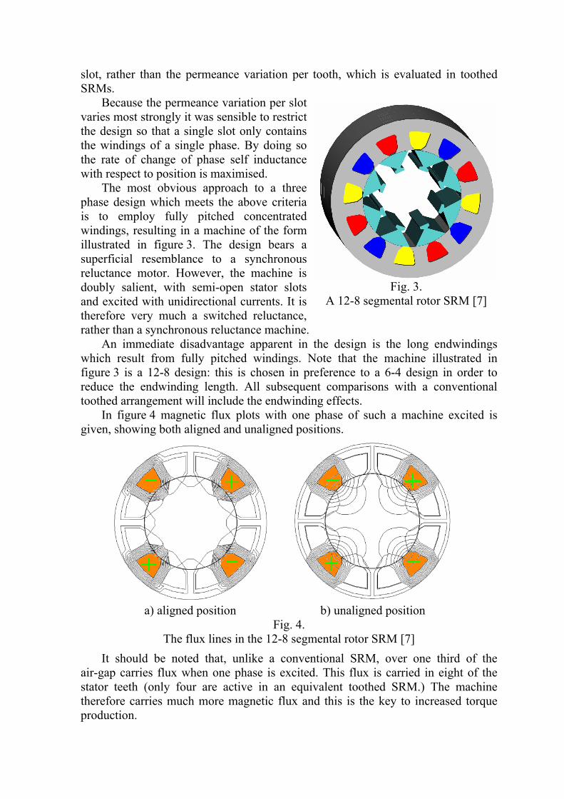
In figure 4 magnetic flux plots with one phase of such a machine excited is given, showing both aligned and unaligned positions.
It should be noted that, unlike a conventional SRM, over one third of the air-gap carries flux when one phase is excited. This flux is carried in eight of the stator teeth (only four are active in an equivalent toothed SRM.) The machine therefore carries much more magnetic flux and this is the key to increased torque production.
Fig. 3.
A 12-8 segmental rotor SRM [7]
a) aligned position b) unaligned position
Fig. 4. The flux lines in the 12-8 segmental rotor SRM [7]

Power Converter Design for an Integrated Modular Motor Drive
Continued improvements in the efficiency, power density, and packaging of power electronics technologies have opened opportunities for new motor drive configurations. Drive designs that allow integration of the drive electronics into the same housing as the machine are attractive in a wide range of applications that include white goods and heating, ventilating, and air conditioning equipment.
The integrated modular motor drive (IMMD) concept (figure 5) takes a major step beyond these previously reported drives by modularizing the motor and the power converter as discussed in more detail further [8].
The IMMD concept is based on the adoption of a modular motor phase-drive unit for the stator assembly (see figure 6)
Fig. 5.
Integrated modular motor drive (IMMD) concept including modular stator assembly [8]
Fig. 6.
IMMD stator pole module consisting of an iron pole piece, a concentrated stator winding and a single-phase power converter [8]

It includes the following key components: i.) A segmented stator pole piece manufactured from either conventional
magnetic steel laminations or better quality soft magnetic composite (SMC) material [9]
ii.) A concentrated coil winding on the stator pole iii.) An autonomous power converter dedicated to the motor pole that includes
the required power electronics and controller to excite the pole winding in a coordinated fashion with the other stator phase-drive units.
The complete stator is fabricated from a number of these poledrive units interconnected to form the annular stator assembly.
A prototype machine consists of five stator coils and a six-pole surface PM rotor (figure 7).
The IMMD power converters are mounted outside the machine in order to simplify electrical testing. Since each phase-drive module is expected to operate independently of the others, dc bus capacitance is built into each module so that external capacitors are not required.
One approach to minimizing the required capacitance is to add a controlled rectifier to each phase-drive unit [10].This approach has the advantage of maintaining symmetry among all of the phase-drive units. The rather obvious disadvantage is the significant increase in the amount of power electronics required for each phase-drive power converter.
The IMMD architecture offers several attractive system advantages, but it also presents serious technical challenges to the power converter designer [11].
Fig. 7.
Experimental five phase demonstrator converter [8]
CONCLUSIONS
In this paper a few types of modular machines are presented. Each one of them has a different construction and the function process easy to understand.
The modular approach can significant reduce the development time and cost due to the power rating scalability and can increase the level of fault tolerance.
REFERENCES
[1] Carlson, C.R. Jr, Hillyer, M.J., "Modular Motor", US Patent no. 4056749, 1977.
[2] Iancu, V., Popa, D.C., Szabó, L., "Fault Tolerant Modular Linear Transverse Flux Reluctance Machines", Journal of Computer Science and Control Systems, vol. 2, no. 2, 2009, pp. 93-96.
[3] Ruba, M., Szabó, L., Hopper, E., "FEM Based Studies on Fault Tolerant Modular Linear Motors," Proceedings of the International Conference on Power Electronics, Intelligent Motion and Power Quality (PCIM '2009), Nürnberg, 2009, pp. 639-644.
[4] Henneberger, G., Viorel, I.A., "Variable Reluctance Electrical Machines", Shaker Verlag, Aachen (Germany), 2001.
[5] Viorel, I.A., Henneberger, G., Blissenbach, R., Lövenstein, L., "Transverse Flux Machines. Their behavior, design, control and applications," Mediamira Publisher, Cluj (Romania), 2003.
[6] Kruse, R., Pfaff, G., Pfeiffer, C., "Transverse Flux Reluctance Motor for Direct Servodrive Applications," Proceedings of the 1998 IEEE Industry Applications Conference, St. Louis (USA), vol. 1, pp. 655-662, 1998.
[7] Mecrow, B.C., Finch, J.W., El-Kharashi, E.A. Jack, A.G. "The Design of Switched Reluctance Motors with Segmental Rotors", Proceedings of the 2002 IEEE Electric Power Applications, vol. 249, pp 245-254
[8] Brown, N.R. Jahns, T.M. Lorenz, R.D. "Power Converter Design for an Integrated Modular Motor Drive", Conference Record of the 2007 IEEE Industry Applications Conference, New Orleans (USA), pp. 1322-1328, 2007.
[9] Szabó, L., Viorel, I.A., Iancu, V., Popa, D.C., "Soft Magnetic Composites Used in Transverse Flux Machines", Oradea University Annals, Electrotechnical Fascicle, 2004, pp. 134-141.
[10] Klumpner, C., Blaabjerg, F., Thorgersen, P., "Converter topologies with low passive components usage for the next generation of integrated motor drives", Proceedings of IEEE Power Electronics Specialist Conference (PESC '03), vol. 2, pp. 568-573, 2003.
[11] Tadros, Y. Ranneberg, J., Shafer, U. "Ring shaped motor-integrated electric drive for hybrid electric vehicles", Proceedings of 2003 European Power Electronics Conference (EPE '03), Toulouse (France), 2003.