Modu-Flo - · PDF file• Modu-Flo modular pumping packages provides a proven,...
13
• Modu-Flo modular pumping packages provides a proven, cost- effective way to assemble customized oil or grease lubrication systems that meet specific requirements by using standard modular components. • Modu-Flo increases opportunities to standardize lube system components and reduces lube maintenance and service costs. • Modu-Flo saves you system design dollars and lead time. • Modu-Flo components are dependable and backed by the industry’s most comprehensive international distributor network – with application expertise, stocked parts and factory-trained service nearby, whenever you are located. Modu-Flo ® Trabon ® Modu-Flo ® Pumps, Reservoirs, Lube Packages, and Accessories
Transcript of Modu-Flo - · PDF file• Modu-Flo modular pumping packages provides a proven,...
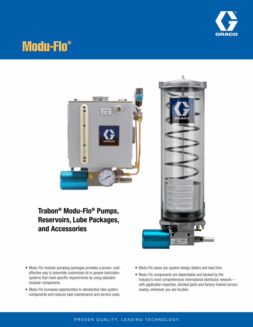
• Modu-Flo modular pumping packages provides a proven, cost-effective way to assemble customized oil or grease lubrication systems that meet specific requirements by using standard modular components.
• Modu-Flo increases opportunities to standardize lube system components and reduces lube maintenance and service costs.
• Modu-Flo saves you system design dollars and lead time.
• Modu-Flo components are dependable and backed by the industry’s most comprehensive international distributor network – with application expertise, stocked parts and factory-trained service nearby, whenever you are located.
Modu-Flo®
Trabon® Modu-Flo® Pumps, Reservoirs, Lube Packages, and Accessories

Trabon® Modu-Flo®
Page 2
L12000
Modu-FIo = True ModularityWide choice of standard modular components helps you meet application requirements more exactly without the added cost of a custom system.
CONTROL:Helps provide as much or as little auto mation and sophistication as your system requires. For details, see page 12.
REMOTE MOUNTING MANIFOLD:One model permits remote wall mount ing of any Modu-Flo pump. See page 5 and 6.
8 PUMP OPTIONS:Three basic pneumatic pumps with sin gle or double action for oil or grease; three double-acting hydraulic-actuated pumps for oil or grease. All with adjustable stroke. 24 VDC and 115 VAC electric pumps available. For details, see pages 3 and 4.
MANIFOLD ACCESSORIES:For data on 3-way air solenoid (for pneu-matic pumps), pressure gauge, fill check, high pressure blowout and pressure switch, see page 6.
PUMP-TO-RESERVOIR MANIFOLD:One model fits all, mounts choice of accessories. See page 5 and 6.
16 RESERVOIR OPTIONS:Tank type and cylindrical, metal and plastic, for pump or remote mounting. For details, see pages 7 and 8.
RESERVOIR ACCESSORIES:High pressure indicators and blowouts plus low-level indicators, switches, and switch assemblies. For details, see page 8.

Page 3
L12000Trabon® Modu-Flo®
PUMPS Pneumatic AL Pump Hydraulic HLJ Pump
There are six Modu-FIo pneumatic and hydraulic actuated pump models for series progressive oil or grease systems. Three pneumatic models carry the AL prefix. They are actuated by air pressure from 40 to 150 psi (2.76 to 10.3 bar), and have a lube-to-air pressure ratio of 30:1. They can be set up to be single-or double- acting, depending on the system requirements.
Three hydraulic-actuated models carry an HLJ prefix. They are double-acting, operate on hydraulic pressure from 200 to 2,000 psi (13.8 to 137.9 bar), and have a lube-to-hydraulic pressure ratio of 5.5:1. The HLJ-5X has a lube to hydraulic ratio of 2.2:1.
All six models fit either the Modu-Flo pump-to-reservoir mounting manifold or the remote wall mounting manifold.
FEATURES / BENEFITS• Adjustable displacement at the turn of a screw provides an infinite
choice of outputs within output range of each pump model.
• All Modu-Flo pumps can be used with either oil or grease
• All Modu-Flo pumps can be used with any of the 16 Modu-Flo reservoirs.
SPECIFICATIONS
When used in single-acting mode, air under pressure is supplied through the inlet port (SA) to chamber (C). This moves the air and lube pistons to the right. This closes the lube inlet port and forces the lubricant already in chamber (B) past the check valve and into the system. Air in chamber (A) must vent out port (DA). A plastic pipe plug with a vent hole is installed in port (DA). After a preset time in terval the solenoid valve shuts off the air supply and vents chamber (C) through port (SA). The spring returns the air and lube pistons, opening chamber (B) to the lube reservoir. This completes a single pump cycle and chamber (B) is primed, ready for the next cycle.
When used in double-acting mode, an additional air or hydraulic supply line is connected to port (DA). When the pistons have been moved to the right, air or hydraulic supply to port (SA) is shut-off and vented. Then, air or hydraulic fluid under pressure is supplied to port (DA), which returns the pistons to their original position. This more powerful return action allows an increased cycle rate of the pump.
ADJUSTING DISPLACEMENTAfter the pump is removed from service, remove the calibrated cap that protects the adjustment screw. Loosen the hex nut and two washers. Then use a screwdriver to turn the adjustment screw out-ward to increase displacement or inward to reduce displacement. Align the calibrated cap parallel to the screw to gauge the amount of change (Cap is graduated at minimum, 1/4, 1/2, 3/4 and maximum output). When the proper setting has been made reposition the washers and tighten the hex nut, replace the cap, and return the pump to service.
Important: System should NOT be operating while adjustments are made; however, it is not necessary to remove the pump or disconnect any lines.
OPERATION
Note: Refer to bulletin L12011 for electric motor operated Modu-Flo pumps.
MODEL ACTUATION ACTION
OUTPUT DISPLACEMENT ADJUSTMENT
RANGE CU. IN. (CM3)
MAX. CYCLES
PER MINUTE*
APPROX. WEIGHT, lb.
(kg)
INPUT OPERATING VOLUME PER
FULL STROKE/CYCLE
CU. IN. (CM3)
ALS-5 Pneumatic Single.010 to .030 (.164 to .492)
303.75 (1.7)
1.06 (17.4)
ALJ-5 Pneumatic Double.010 to .030 (.164 to .492)
603.75 (1.7)
2.09 (34.3)
ALS-25 Pneumatic Single .030 to .120
(.492 to 1.966) 30
4.75 (2.15)
4.20 (68.8)
ALJ-25 Pneumatic Double .030 to .120
(.492 to 1.966) 60
4.75 (2.15)
8.28 (135.7)
ALS-50 Pneumatic Single.060 to .240
(.983 to 3.933)30
6.5 (2.9)
8.40 (137.6)
ALJ-50 Pneumatic Double.060 to .240
(.983 to 3.933)60
6.5 (2.9)
16.56 (271.4)
NOTE: AL (air) pumps for single- or double-acting operation have the same part number. (See page 4.)
HLJ-5 Hydraulic Double.010 to .030 (.164 to .492)
1003.375 (1.53)
0.35 (5.7)
HLJ-5X Hydraulic Double.030 to .092 (.492 to 1.51)
503.375 (1.53)
0.28 (4.7)
HLJ-25 Hydraulic Double.030 to .120
(.492 to 1.966) 50
5.5 (2.49)
1.38 (22.6)
NOTE: Min/Max. air pressure for AL pumps is 40 to 150 psi (2.76 to 10.3 bars).Min/Max. hydraulic pressure for HLJ 5 AND 25 pumps is 200 to 2,000 psi (13.8 to 137.9 bars), and 3000 psi (max) (207 bar) for the HLJ-5X. AL Pumps have a lube to air pressure ratio of 30:1. HLJ-5 and 25 Pumps have a lube to hydraulic pressure ratio of 5.5:1. HLJ-5X is 2.2:1. *Do not exceed 10 cpm with grease (3 seconds on, 3 seconds off).

Trabon® Modu-Flo®
Page 4
L12000
HYDRAULIC PUMPS (HLJ)
ORDERING INFORMATIONNOTE: Single- and double-acting pneumatic pumps (AL) have the same part number.
PUMP DIMENSIONS / Inches (mm)
PNEUMATIC PUMPS (AL)
*Test/Bleed port is used for bleeding air out of pump. Back out setscrew one or two turns while pump is in the dispense stroke. Close setscrew when pump is on return stroke to prevent air from being sucked in. Repeat process until air-free lubricant comes from vent hole.
**Slows operation of pneumatic pumps and reduces system pressure spikes.
PUMP MODEL
DIMENSIONS / Inches (mm)
A B C E F G H
AL-58.281 (210.3)
2.250 (57.2
1.250 (31.8)
2.125 (54)
2.875 (73)
3.656 (92.9)
1.750 (44.5)
AL-2510.375 (263.5)
2.250 (57.2)
1.250 (31.8)
2.875 (73)
3.980 (101.1)
3.656 (92.9)
2.750 (69.9)
AL-5012.812 (325.4)
2.250 (57.2)
1.250 (31.8)
3.188 (81)
4.250 (108)
4.808 (122.1)
3.750 (95.3)
COMPONENT ORDERING - Repair KitsDescription Part No. Old Part No.
For AL-5, single - or double-acting 563902 560-001-021
For AL-25, single - or double-acting 563903 560-001-031
For AL-50, single - or double-acting 563904 560-001-041
For HLJ-5 563905 560-001-051
For HLJ-25 563906 560-001-061
For HLJ-5X 563925 560-001-940
COMPONENT ORDERING - New PumpsDescription Part No. Old Part No.
AL-5, pneumatic 30:1, .010-.030 in3/stroke, .164-.492 cc
563304 521-000-001
AL-25, pneumatic 30:1, .030-.120 in3/stroke, .492-1.966 cc
563306 521-000-021
AL-50, pneumatic 30:1, .060-.240 in3/stroke, .938-3.933 cc
563308 521-000-041
HLJ-5, hydraulic 5.5:1, .010-.030 in3/stroke, .164-.492 cc
563305 521-000-011
HLJ-25, hydraulic 5.5:1, .030-.120 in3/stroke, .492-1.966 cc
563307 521-000-031
HLJ-5X, hydraulic 2.2:1, .030-.092 in3/stroke, .492-1.51 cc
563345 521-005-900
Air restrictor valve** 563072 463-410-080

Page 5
L12000Trabon® Modu-Flo®
BASEPLATE MANIFOLD KITSGraco
Part NumberLubriquip
Part NumberThread Mount
Outlet Check Valve
System Fill Check Valve
1450 psi Blowout Assembly
0-3000 psi Gauge
563329 521-001-540 NPSF (NPT) Reservoir No No None None
563324 521-001-180 NPSF (NPT) Reservoir Yes Yes Standard Dry
563331 521-001-790 NPSF (NPT) Reservoir Yes Yes Tubed** Dry
563355 521-010-820 SAE Reservoir Yes Yes Standard Liquid-filled
563333 521-002-140 NPSF (NPT) Reservoir Yes Yes Tubed** Liquid-filled
563336 521-003-920 NPSF (NPT) Reservoir Yes Yes Tubed** None
563323 521-001-170 NPSF (NPT) Wall/Remote* Yes Yes Standard None
563330 521-001-780 NPSF (NPT) Wall/Remote* Yes Yes Tubed** None
*Manifolds are intended for gravity feed (oil) or spring loaded follower feed (grease) only; not for use with header systems.**Includes 1/8” NPT female spud.
Pump-to-wall or remote manifold (563323) (Shown assembled)
Pump-to-reservoir manifold (563324)(Shown assembled) MANIFOLDS
There are just two types of modular design manifolds for direct-to-reservoir or remote mounting of Modu-Flo Pumps. All manifolds mount any pneumatic, electric, or hydraulic Modu-Flo pump. This allows the pump to be removed without disturbing existing
lines or emptying the reservoir. Also, each Modu-Flo manifold may be used as is, or can be fitted with a choice of matched accessories. (See illustrations and listings that follow.)
ORDERING INFORMATIONYou can order the manifold and accessories you want separately or with one part number, as shown below.
DIMENSIONS / Inches (mm)
Pump-to-reservoir manifold Manifold for remote mounting of pump (563323)

Trabon® Modu-Flo®
Page 6
L12000
ACCESSORIES FOR BASEPLATE MANIFOLDS
DescriptionNPT Graco
Part NumberNPT Lubriquip Part Number
SAE Graco Part Number
SAE Lubriquip Part Number
Outlet Check Valve 563207 509-360-030 563053 463-001-587
System Fill Check Valve 563211 509-365-030 563056 463-001-600
Standard Blowout Assembly (1450 psi / 99.9 bar) 563179 509-206-100 563180 509-206-110
Tubed Blowout Assembly (1450 psi / 99.9 bar) 563186 509-220-101 n/a n/a
Standard (Dry) Pressure Gauge (3000 psi / 206.9 bar) 557864 543-362-000 n/a n/a
Liquid-Filled Pressure Gauge (3000 psi / 206.9 bar) 557866 543-711-380 557280 493-020-242
MANIFOLD ORDERING INFORMATION (Cont.)You can order the manifold and accessories you want separately or with one part number, as shown below.
Page 7
L12000Trabon® Modu-Flo®
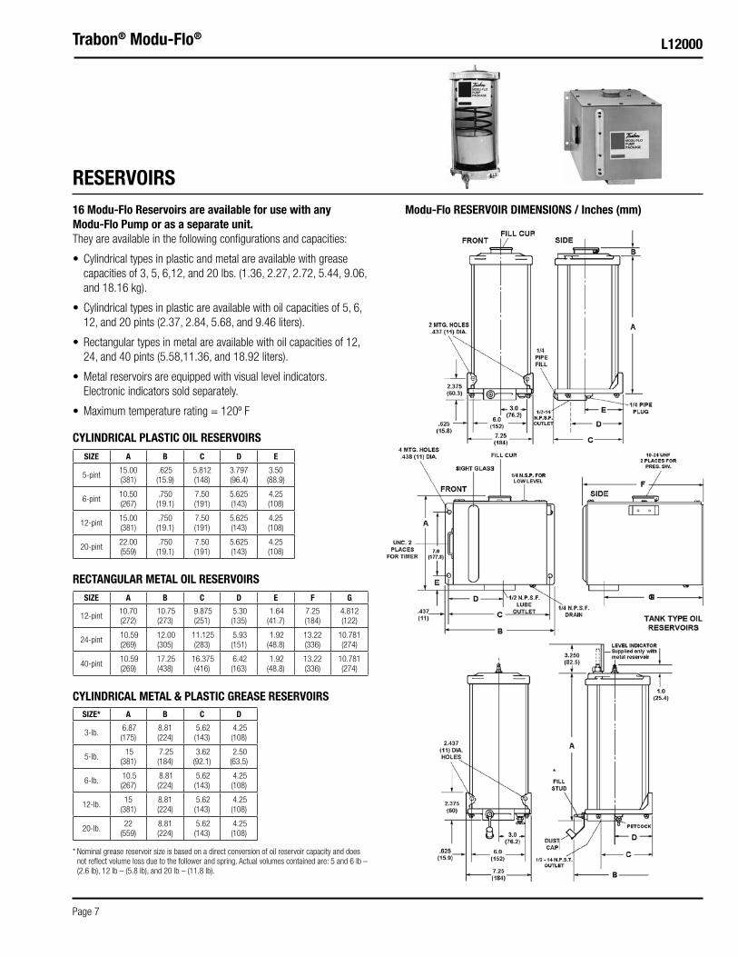
16 Modu-Flo Reservoirs are available for use with any Modu-Flo Pump or as a separate unit.They are available in the following configurations and capacities:
• Cylindrical types in plastic and metal are available with grease capacities of 3, 5, 6,12, and 20 lbs. (1.36, 2.27, 2.72, 5.44, 9.06, and 18.16 kg).
• Cylindrical types in plastic are available with oil capacities of 5, 6, 12, and 20 pints (2.37, 2.84, 5.68, and 9.46 liters).
• Rectangular types in metal are available with oil capacities of 12, 24, and 40 pints (5.58,11.36, and 18.92 liters).
• Metal reservoirs are equipped with visual level indicators. Electronic indicators sold separately.
• Maximum temperature rating = 120º F
RESERVOIRSModu-Flo RESERVOIR DIMENSIONS / Inches (mm)
CYLINDRICAL PLASTIC OIL RESERVOIRS
RECTANGULAR METAL OIL RESERVOIRS
CYLINDRICAL METAL & PLASTIC GREASE RESERVOIRS
*
SIZE A B C D E
5-pint15.00 (381)
.625 (15.9)
5.812 (148)
3.797 (96.4)
3.50 (88.9)
6-pint10.50 (267)
.750 (19.1)
7.50 (191)
5.625 (143)
4.25 (108)
12-pint15.00 (381)
.750 (19.1)
7.50 (191)
5.625 (143)
4.25 (108)
20-pint22.00 (559)
.750 (19.1)
7.50 (191)
5.625 (143)
4.25 (108)
SIZE A B C D E F G
12-pint10.70 (272)
10.75 (273)
9.875 (251)
5.30 (135)
1.64 (41.7)
7.25 (184)
4.812 (122)
24-pint 10.59 (269)
12.00 (305)
11.125 (283)
5.93 (151)
1.92 (48.8)
13.22 (336)
10.781 (274)
40-pint 10.59 (269)
17.25 (438)
16.375 (416)
6.42 (163)
1.92 (48.8)
13.22 (336)
10.781 (274)
SIZE* A B C D
3-lb. 6.87 (175)
8.81 (224)
5.62 (143)
4.25 (108)
5-lb. 15
(381) 7.25 (184)
3.62 (92.1)
2.50 (63.5)
6-lb. 10.5 (267)
8.81 (224)
5.62 (143)
4.25 (108)
12-lb.15
(381)8.81 (224)
5.62 (143)
4.25 (108)
20-lb.22
(559)8.81 (224)
5.62 (143)
4.25 (108)
* Nominal grease reservoir size is based on a direct conversion of oil reservoir capacity and does not reflect volume loss due to the follower and spring. Actual volumes contained are: 5 and 6 lb – (2.6 lb), 12 lb – (5.8 lb), and 20 lb – (11.8 lb).
Trabon® Modu-Flo®
Page 8
L12000
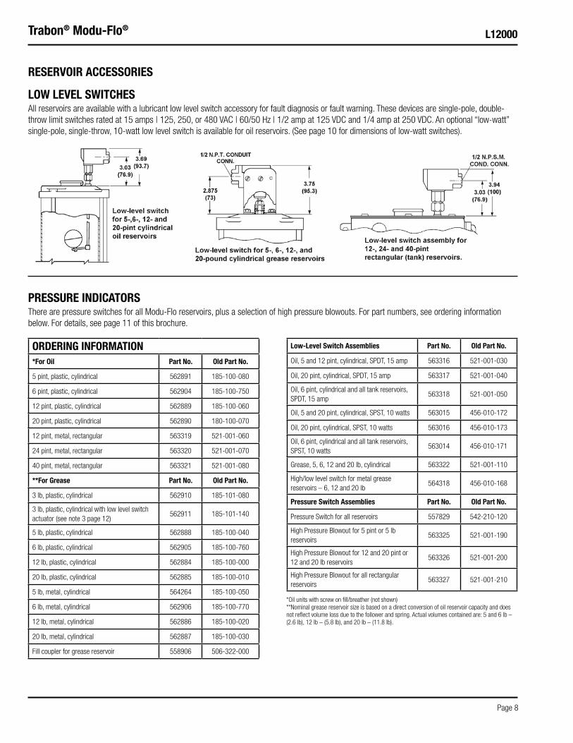
RESERVOIR ACCESSORIES
PRESSURE INDICATORSThere are pressure switches for all Modu-Flo reservoirs, plus a selection of high pressure blowouts. For part numbers, see ordering information below. For details, see page 11 of this brochure.
ORDERING INFORMATION*For Oil Part No. Old Part No.
5 pint, plastic, cylindrical 562891 185-100-080
6 pint, plastic, cylindrical 562904 185-100-750
12 pint, plastic, cylindrical 562889 185-100-060
20 pint, plastic, cylindrical 562890 180-100-070
12 pint, metal, rectangular 563319 521-001-060
24 pint, metal, rectangular 563320 521-001-070
40 pint, metal, rectangular 563321 521-001-080
**For Grease Part No. Old Part No.
3 lb, plastic, cylindrical 562910 185-101-080
3 lb, plastic, cylindrical with low level switch actuator (see note 3 page 12)
562911 185-101-140
5 lb, plastic, cylindrical 562888 185-100-040
6 lb, plastic, cylindrical 562905 185-100-760
12 lb, plastic, cylindrical 562884 185-100-000
20 lb, plastic, cylindrical 562885 185-100-010
5 lb, metal, cylindrical 564264 185-100-050
6 lb, metal, cylindrical 562906 185-100-770
12 lb, metal, cylindrical 562886 185-100-020
20 lb, metal, cylindrical 562887 185-100-030
Fill coupler for grease reservoir 558906 506-322-000
Low-Level Switch Assemblies Part No. Old Part No.
Oil, 5 and 12 pint, cylindrical, SPDT, 15 amp 563316 521-001-030
Oil, 20 pint, cylindrical, SPDT, 15 amp 563317 521-001-040
Oil, 6 pint, cylindrical and all tank reservoirs, SPDT, 15 amp
563318 521-001-050
Oil, 5 and 20 pint, cylindrical, SPST, 10 watts 563015 456-010-172
Oil, 20 pint, cylindrical, SPST, 10 watts 563016 456-010-173
Oil, 6 pint, cylindrical and all tank reservoirs, SPST, 10 watts
563014 456-010-171
Grease, 5, 6, 12 and 20 lb, cylindrical 563322 521-001-110
High/low level switch for metal grease reservoirs – 6, 12 and 20 lb
564318 456-010-168
Pressure Switch Assemblies Part No. Old Part No.
Pressure Switch for all reservoirs 557829 542-210-120
High Pressure Blowout for 5 pint or 5 lb reservoirs
563325 521-001-190
High Pressure Blowout for 12 and 20 pint or 12 and 20 lb reservoirs
563326 521-001-200
High Pressure Blowout for all rectangular reservoirs
563327 521-001-210
LOW LEVEL SWITCHESAll reservoirs are available with a lubricant low level switch accessory for fault diagnosis or fault warning. These devices are single-pole, double-throw limit switches rated at 15 amps | 125, 250, or 480 VAC | 60/50 Hz | 1/2 amp at 125 VDC and 1/4 amp at 250 VDC. An optional “low-watt” single-pole, single-throw, 10-watt low level switch is available for oil reservoirs. (See page 10 for dimensions of low-watt switches).
*Oil units with screw on fill/breather (not shown)**Nominal grease reservoir size is based on a direct conversion of oil reservoir capacity and does not reflect volume loss due to the follower and spring. Actual volumes contained are: 5 and 6 lb – (2.6 lb), 12 lb – (5.8 lb), and 20 lb – (11.8 lb).
Page 9
L12000Trabon® Modu-Flo®
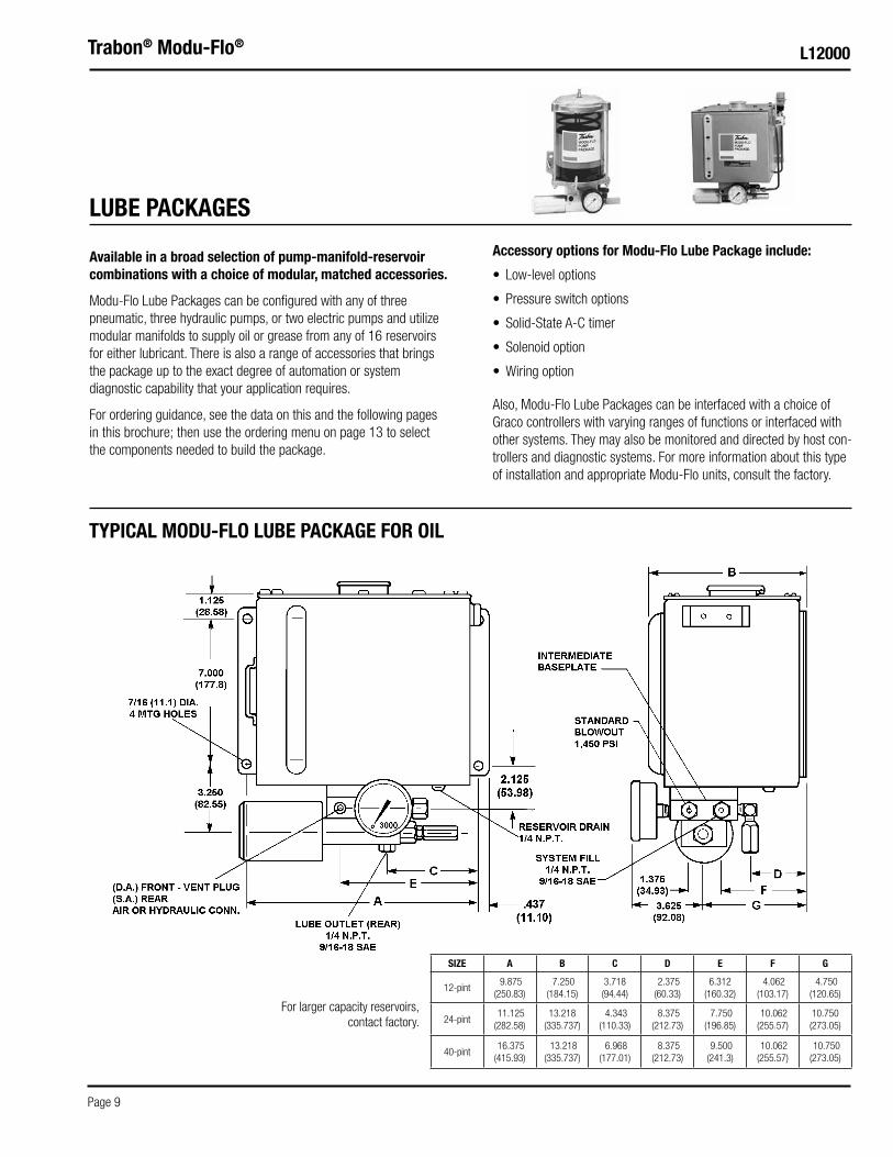
Available in a broad selection of pump-manifold-reservoir combinations with a choice of modular, matched accessories.
Modu-Flo Lube Packages can be configured with any of three pneumatic, three hydraulic pumps, or two electric pumps and utilize modular manifolds to supply oil or grease from any of 16 reservoirs for either lubricant. There is also a range of accessories that brings the package up to the exact degree of automation or system diagnostic capability that your application requires.
For ordering guidance, see the data on this and the following pages in this brochure; then use the ordering menu on page 13 to select the components needed to build the package.
LUBE PACKAGES
Also, Modu-Flo Lube Packages can be interfaced with a choice of Graco controllers with varying ranges of functions or interfaced with other systems. They may also be monitored and directed by host con-trollers and diagnostic systems. For more information about this type of installation and appropriate Modu-Flo units, consult the factory.
TYPICAL MODU-FLO LUBE PACKAGE FOR OIL
Accessory options for Modu-Flo Lube Package include:
• Low-level options
• Pressure switch options
• Solid-State A-C timer
• Solenoid option
• Wiring option
For larger capacity reservoirs, contact factory.
SIZE A B C D E F G
12-pint 9.875
(250.83) 7.250
(184.15)3.718 (94.44)
2.375 (60.33)
6.312 (160.32)
4.062 (103.17)
4.750 (120.65)
24-pint 11.125 (282.58)
13.218 (335.737)
4.343 (110.33)
8.375 (212.73)
7.750 (196.85)
10.062 (255.57)
10.750 (273.05)
40-pint 16.375 (415.93)
13.218 (335.737)
6.968 (177.01)
8.375 (212.73)
9.500 (241.3)
10.062 (255.57)
10.750 (273.05)

Trabon® Modu-Flo®
Page 10
L12000
TYPICAL LUBE PACKAGE CHOICES AVAILABLE FOR OIL OR GREASE SYSTEMS UTILIZING PNEUMATIC OR HYDRAULIC POWER.
RESERVOIR SIZE* A B D E F
3 PT/LB Capacity 5.625
(142.88) 7.37
(187.2) 3.250 (82.55)
5.625 (142.88)
4.937 (125.40)
5 PT/LB Capacity 3.781 (96.04)
15.500 (393.7)
1.437 (36.50)
3.781 (96.04)
3.093 (78.56)
6 PT/LB Capacity5.625
(142.88) 11.000 (279.4)
3.250 (82.55)
5.625 (142.88)
4.937 (125.40)
12 PT/LB Capacity5.625
(142.88)15.500 (393.7)
3.250 (82.55)
5.625 (142.88)
4.937 (125.40)
20 PT/LB Capacity5.625
(142.88)22.500 (571.5)
3.250 (82.55)
5.625 (142.88)
4.937 (125.40)
* Nominal grease reservoir size is based on a direct conversion of oil reservoir capacity and does not reflect volume loss due to the follower and spring. Actual volumes contained are: 5 and 6 lb – (2.6 lb), 12 lb – (5.8 lb), and 20 lb – (11.8 lb).
RESERVOIR FILL1/4 PIPE PLUG (OIL)FILL STUD (GREASE)
SYSTEM FILL DOWN STREAM OF PUMP1/4 N.P.T.9/16-18 SAE

Page 11
L12000Trabon® Modu-Flo®
Oil pressure switch is factory set at 1,150 (79.3 bar). However, it is field adjustable from 400 to 4,700 psi (27.6 to 324 bar). For all Modu-Flo reservoirs, it is rated 5 amps @ 115/230 VAC... 3 amps @ 30 VDC inductive load and 5 amps @ 30 VDC resistive load. It is option P1 on the menu.
High pressure blowout switch options P2, P3, and P4 are single-pole, double-throw type and rated 15 amps @ 125, 250 and 480 VAC, 1/2 amp @ 125 VDC, and 1/4 amp @ 250 VDC. Option P5 is the standard blowout with 1,450 psi rating. For grease systems, replace blowout disk with one having a higher rating.
PRESSURE PROTECTION
LUBE PACKAGE ACCESSORIES
For all rectangular reservoirs specify option P4.
For 6-, 12- and 20-pound or 6-, 12- and 20-pint capacity cylindrical reservoirs, specify option P3.
Hi-Pressure Blowout Switch Option“P2” - 5 pt/lb cylindrical reservoirs“P3” - 6, 12, and 20 pt/lb cylindrical reservoirs
SPARE OR REPLACEMENT BLOWOUT DISCS FOR PRESSURE PROTECTION
psi (bar) Color Code Graco Part NumberGraco 6-Pack Part Number
Lubriquip Part NumberLubriquip 6-Pack
Part Number
900 (62.0) Black 557431 n/a 509-290-000 560-900-250
1175 (81.0) Green 557432 n/a 509-291-000 n/a
1450 (99.9) Yellow 557433 563962 509-292-000 560-900-270
1750 (120.7) Red 557434 563963 509-293-000 560-900-280
2050 (141.4) Orange 557435 563964 509-294-000 560-900-290
2350 (162.0) Aluminum 557436 563965 509-295-000 560-900-300
2650 (182.6) Pink 557437 n/a 509-296-000 560-900-310
2950 (203.0) Blue 557438 563966 509-297-000 560-900-320
3250 (220.1) Purple 557439 n/a 509-298-000 560-900-330
*Discs up to 2,350 psi have a tolerance of ± 500 psi. Discs greater than 2,350 psi have a tolerance of ± 20%.

Trabon® Modu-Flo®
Page 12
L12000
GLC 4400 CONTROLLER9-30 VDC or 100 VAC to 240 VAC, 50/60 Hz, 24 watts
GLC 4400 gives you programmed lubrication cycles for optimal machine performance. Customize your lubrication time, cycle counts, and machine counts for maximum precision and productivity. Inputs include: Cycle Switch, Machine Count Switch, Reservoir Level Indication Switch, and Remote Manual Run Switch. Outputs include: Pump Control Signal, Low Level Alarm Signal, Cycle Alarm Signal, and System OK Signal.
SOLID STATE AC TIMER
SOPHISTICATED CONTROLLook to Graco for the ideal controller to meet your system requirements and your budget limitations. For details, contact your Graco/Trabon distributor or visit www.graco.com.
OPERATION/SERVICEFor operation and service instructions on Modu-Flo components, refer to Trabon bulletin L42000.
The Solid State Timer utilizes 110/220 VAC 60/50 Hz input, and permits total cycle times to be set at any period from 30 seconds to 32 hours. “On” time during total cycle time can be set from 12 seconds to 13 minutes, and takes place at the beginning of each period. For data sheet on timer, see Lit. No 14521.
Valve is 115 VAC, 3-way, pneumatic, normally closed with a manual override button to simplify system testing, line filling, and line bleeding (option S1). A 24 VDC version is also available (option S2).
CYLINDRICAL RESERVOIR MOUNTING
RECTANGULAR RESERVOIR MOUNTING
SOLENOID VALVE OPTION110/120 VAC, 0.11A in-rush, 0.07A holding; 24 VDC, 8.5 W
LOW-LEVEL PROTECTION
Low-level switch assembly for use with 5- and 12-pint capacity cylindrical oil reservoirs is option L1 on the ordering menu on the back cover of this brochure.A low-level switch assembly for the 20-pint capacity cylindrical reservoir is option L2.
Low-level switch option for all grease reservoirs (except 3lb and 40lb) is option L4
“Low-watt” low-level switch assembly for 5- and 12-pint capacity plastic cylindrical reservoirs is option L5.
“Low-watt” low-level switch assembly for 20-pint capacity plastic cylindrical oil reservoir is option L6.
“Low-watt” low-level switch assembly for 12-, 24- and 40-pint capacity rectangular tanks and 6-pint cylindrical oil reservoir is option L7.
“Low-watt” dual level switch assembly. (Low and low shutdown) for 12, 24 and 40 pint capacity rectangular tanks is option L8.
Low-level switch assembly for 12-, 24- and 40-pint capacity rec tangular tank and the 6-pint cylindrical oil reservoir is option L3.
Modular low-level switch assemblies are all single-pole, double-throw type rated 15 amps @ 125, 250 and 480 VAC | 60/50 Hz | 1/2 amp @125 and 1/4 amp @ 250 VDC. An optional “low-watt” single-pole, single-throw, 10-watt low-level switch is available for oil reservoirs.
LUBE PACKAGE ACCESSORIES (Cont.)

MPP - XXX - XXX - XX - XX - XX - XX - XX - XXX - XXRESERVOIR OPTION - SEE FOOTNOTE 1
OP1 - 5 PINT OIL CYLINDRICAL PLASTIC - 562891 - (185-100-080)OP2 - 12 PINT OIL CYLINDRICAL PLASTIC - 562889 - (185-100-060)OP3 - 20 PINT OIL CYLINDRICAL PLASTIC - 562890 - (185-100-070)OP4 - 6 PINT OIL CYLINDRICAL PLASTIC - 562904 - (185-100-750)T1 - 12 PINT OIL TANK - 563319 - (521-001-060)T2 - 24 PINT OIL TANK - 563320 - (521-001-070)T3 - 40 PINT OIL TANK - 563321 - (521-001-080)GP1 - 5 LB GREASE CYLINDRICAL PLASTIC - 562888 - (185-100-040)GP2 - 12 LB GREASE CYLINDRICAL PLASTIC - 562884 - (185-100-000)GP3 - 20 LB GREASE CYLINDRICAL PLASTIC - 562885 - (185-100-010)GP4 - 6 LB GREASE CYLINDRICAL PLASTIC - 562905 - (185-100-760)GP5 - 3 LB GREASE CYLINDRICAL PLASTIC - 562910 - (185-101-080) - SEE FOOTNOTE 3GM1 - 5 LB GREASE CYLINDRICAL METAL - 564264 - (185-100-050)GM2 - 12 LB GREASE CYLINDRICAL METAL - 562886 - (185-100-020)GM3 - 20 LB GREASE CYLINDRICAL METAL - 562887 - (185-100-030)GM4 - 6 LB GREASE CYLINDRICAL METAL - 562906 - (185-100-770)
BASEPLATE THREAD OPTION - SEE FOOTNOTE 5
NPT - INTERMEDIATE BASEPLATE - 563324 - (521-001-180)SAE - INTERMEDIATE BASEPLATE - 563355 - (521-010-820)BSPP - CONTACT FACTORY FOR PART NUMBER - SEE FOOTNOTE 4THE ABOVE KITS INCLUDE “G2” GAUGE AND “P5” STANDARD BLOWOUT. SEE PAGE 5 FOR MORE OPTIONS.
*PUMP OPTION
A0 - NONEA1 - ALS - 5 AIR, S.A., 30:1 (.010 - .030 IN3/STROKE) - 563304 - (521-000-001)A2 - ALJ - 5 AIR, D.A. - 563304 - (521-000-001)A3 - ALS - 25 AIR, S.A., 30;1 (.030 - .120 IN3/STROKE) - 563306 - (521-000-021)A4 - ALJ - 25 AIR, D.A. - 563306 - (521-000-021)A5 - ALS - 50 AIR, S.A., 30:1 (.060 - .240 IN3/STROKE) - 563308 - (521-000-041)A6 - ALJ - 50 AIR, D.A. - 563308 - (521-000-041)H1 - HLJ - 5 HYDR, D.A., 5.5:1 (.010 - .030 IN3/STROKE) - 563305 - (521-000-011)H2 - HLJ - 25 HYDR, D.A., 5.5:1 (.030 - .120 IN3/STROKE) - 563307 - (521-000-031)H3 - HLJ - 5X HYDR, D.A., 2.2:1 (.030 - .092 IN3/STROKE) - 563345 - (521-005-900)E3 - 24 VDC, W/20 FT CABLE - 563356 - (521-010-915) - SEE FOOTNOTE 2E4 - 24 VDC, W/TIMER AND 20 FT CABLE - DISCONTINUED - (521-010-916) - SEE FOOTNOTE 2E5 - 115 VAC, W/20 FT CABLE - 563346 - (521-007-060) - SEE FOOTNOTE 2
*PRESSURE GAUGE OPTION
G1 - NO GAUGEG2 - 3000 PSI STANDARD GAUGE - 557864 - (543-362-000) - included with baseplate 563324G3 - 3000 PSI LIQUID FILL GAUGE - 557866 - (543-711-380) - included with baseplate 563333
*LOW LEVEL OPTION
L1 - 5 AND 12 PINT CYLINDRICAL OIL RESERVOIR, SPDT, 15 AMP - 563316 - (521-001-030)L2 - 20 PINT CYLINDRICAL OIL RESERVOIR, SPDT, 15 AMP - 563317 - (521-001-040)L3 - 12, 24 AND 40 PINT TANK AND 6 PINT CYLINDRICAL OIL RESERVOIR, SPDT, 15 AMP - 563318 - (521-001-050)L4 - ALL GREASE RESERVOIRS EXCEPT 3 LB AND 40 LB - 563322 - (521-001-110) - SEE FOOTNOTE 3L5 - 5 AND 12 PINT CYLINDRICAL OIL RESERVOIR, SPST, 10 WATTS - 563015 - (456-010-172)L6 - 20 PINT CYLINDRICAL OIL RESERVOIR, SPST, 10 WATTS - 563016 - (456-010-173)L7 - 12, 24 AND 40 PINT TANK AND 6 PINT CYLINDRICAL OIL RESERVOIR, SPST, 10 WATTS - 563014 - (456-010-171)L8 - 12, 24 AND 40 PINT TANK, DUAL SPST, 10 WATT SWITCH (ONE LOW, ONE SHUTDOWN) - 564322 - (456-020-951)
*PRESSURE INDICATOR OPTION - SEE FOOTNOTE 5
P1 - PRESSURE SWITCH ALL SIZES - 557829 - (541-210-120)P2 - HIGH PRESSURE BLOWOUT SWITCH, 5 PT/LB CYLINDRICAL - 563325 - (521-001-190)P3 - HIGH PRESSURE BLOWOUT SWITCH, 6, 12 AND 20 PT/LB CYLINDRICAL - 563326 - (521-001-200)P4 - HIGH PRESSURE BLOWOUT SWITCH, ALL TANKS - 563327 - (521-001-210)P5 - STANDARD BLOWOUT, 1450 PSI - 563179 - (509-206-100) - included with baseplate
*SOLENOID VALVE OPTION S.A. PNEUMATIC PUMPS ONLY (NOT AVAILABLE WITH SAE BASEPLATE)
S1 - 115 VAC, 3-WAY PNEUMATIC SOLENOID VALVE - 563315 - (521-001-020)S2 - 24 VDC, 3-WAY PNEUMATIC SOLENOID VALVE - 563332 - (521-002-100)
*TIMER/CONTROLLER
C10 - SOLID-STATE AC TIMER, ALL TANKS - 563339 - (521-004-500)C11 - SOLID-STATE AC TIMER, 5 PT/LB CYLINDRICAL - 563340 - (521-004-510)C12 - SOLID-STATE AC TIMER, 6, 12 AND 20 PT/LB CYLINDRICAL - 563341 - (521-004-520)
*WIRING OPTION
W1 - SOLENOID VALVE WIRED TO TIMER*OMIT WHEN NOT REQUIRED
©2016 Graco Inc. Form No. L12000 Rev. D 8/16 Printed in U.S.A. All other brand names or marks are used for identification purposes and are trademarks of their respective owners. All written and visual data contained in this document are based on the latest product information available at the time of publication. Graco reserves the right to make changes at any time without notice.
Contact us today!To receive product information or talk with a Graco representative, call 800-533-9655 or visit us online at www.graco.com.
LEGACY ORDERING MENU (for reference only)
(1) Nominal grease reservoir size is based on a direct conversion of oil reservoir capacity and does not reflect volume loss due to the follower and spring. Actual volumes contained are: 5 and 6 lb (2.6 lb), 12 lb (5.8 lb), and 20 lb (11.8 lb).
(2) Reference Bulletin L12011 for electric Modu-Flo pump specifications.(3) 3-lb reservoir with low level switch actuator available as p/n 562911 (185-101-140). Order switch and bracket assembly 563272
(510-599-000) separately.
(4) Baseplate code “BSP” was simply an abbreviation for Baseplate, when NPSF was the only thread option offered. British thread is indicated by “BSPP” with both Ps included. If the customer confirms that BSPP thread is required, contact Graco for the BSPP baseplate option.
(5) Blowout assemblies P2 through P5 include standard Yellow blowout disc for use with oil systems. When used with grease, order Red, Orange, or other blowout disc from table on page 11.


![Introduction_ppt [Uyumluluk Modu]](https://static.fdocuments.in/doc/165x107/577c82351a28abe054afe196/introductionppt-uyumluluk-modu.jpg)


![ch06 [Uyumluluk Modu] - baskent.edu.tr](https://static.fdocuments.in/doc/165x107/61f7844f340bfa3d1d5307d8/ch06-uyumluluk-modu-.jpg)