Modern timber bridges – an international perspective · Fig 1. Roseman Bridge(1883) – one of...
6
PAPER 26 The Structural Engineer 16 September 2008 Andrew Lawrence MA (Cantab), PGCDMM, CEng, MICE, MIStructE Associate, Arup Introduction Timber bridges can have many advantages. A high strength to weight ratio enables relatively lightweight structures to be built, minimising the loads on any new or existing foundations and maximising the potential for off-site fabrication of large compo- nents or even entire bridges. Timber is also our only renewable construction material and can also offer a structure in complete sympathy with the natural surroundings. However, there are key issues which need to be addressed – most importantly for a structure directly exposed to the weather, ensuring an adequate design life without premature decay due to fungal attack. Protected structures normally dry down to 12-16%, well below the 20% or so threshold for fungal spores to germinate. Bridge structures, in contrast, will routinely experience surface wetting, and a protection strategy, either in a physical form, or as an applied preservative, is essential. Other issues are the risk of arson, and for road bridges resisting the high point loads on the parapets and damage to finishes due to differential live load deflections. This paper is based on material collected during study tours of southern Norway, Germany, New York State, Oregon, Iowa and Wisconsin undertaken during 2007 and 2008 and supported by the Pai Lin Li Travel Award, awarded by the Institution of Structural Engineers’ Educational Trust. The paper discusses the recent revival of timber bridges in Europe and the United States. It aims to help designers understand the possibilities for timber in bridges in terms of materials and structural form, and to demon- strate how some of the issues discussed in the previous para- graph have been addressed. Fig 1. Roseman Bridge(1883) – one of the famous bridges of Madison County and an example of a Town Lattice truss / Fig 2. Typical American design comprising transverse glulam deck panels on glulam beams (Laminated Concepts, NY) Keywords: Bridges, Timber, USA, Preservatives, Glulam, Stress laminated timber, Norway, Germany © Andrew Lawrence 1 2 Pai Lin Li Travel Award 2007 To be held at IStructE, 11 Upper Belgrave Street, London SW1X 8BH on 20 November 2008 at 18:00h Modern timber bridges – an international perspective The United States Until the Industrial Revolution brought cheap wrought iron as well as heavier vehicles, timber was the main material for minor road bridges. Almost all the surviving timber bridges in both North America and Central Europe are covered (trusses or occa- sionally arches) typically dating from the 19th Century (Fig 1). The purpose of the roof and walls was simply to keep the main struc- tural members dry to stop them rotting. When the cladding failed it was relatively cheap and easy to replace; roof leaks were visible and anyway were unlikely to be an immediate problem because the insides of the bridges were well ventilated allowing the main structural members to dry before decay could take hold. Unfortunately, of the 800 surviving covered bridges in the USA, about three are lost each year through arson, the thin timber cladding being particularly easy to ignite. Many of the bridges now have security cameras or sprinklers. Advances in timber preservatives in the early 1900s offered effective chemical protection against fungal attack, thereby enabling simple joist and plank bridges without the expense of a roof. These were originally limited by the size of the sawn mate- rial to about 6m spans, but the development of waterproof glues in the 1940s allowed the fabrication of laminated members and today the US has over 40 000 timber bridges with typical spans from 6 to 12m or so. Timber bridges remain a popular choice for low volume roads because they can be installed and maintained by the local counties’ in-house teams without buying in expensive lifting equipment or specialist labour. Since the late 1980s the USDA Forest Products Laboratory has done much to improve the economics, spans and durability of these designs. There are three requirements for effective preservative treat- The Pai Lin Li Travel Award, donated by the family of the late Pai Lin Li, was granted in 2007 to the author in order to spend up to 6 weeks abroad studying modern day use of timber bridges in Norway, Germany and the USA.
Transcript of Modern timber bridges – an international perspective · Fig 1. Roseman Bridge(1883) – one of...
PAPER
26 The Structural Engineer 16 September 2008
AndrewLawrenceMA (Cantab),PGCDMM, CEng,MICE, MIStructE Associate, Arup
IntroductionTimber bridges can have many advantages. A high strength toweight ratio enables relatively lightweight structures to be built,minimising the loads on any new or existing foundations andmaximising the potential for off-site fabrication of large compo-nents or even entire bridges. Timber is also our only renewableconstruction material and can also offer a structure in completesympathy with the natural surroundings.
However, there are key issues which need to be addressed –most importantly for a structure directly exposed to the weather,ensuring an adequate design life without premature decay due tofungal attack. Protected structures normally dry down to 12-16%,well below the 20% or so threshold for fungal spores to germinate.Bridge structures, in contrast, will routinely experience surfacewetting, and a protection strategy, either in a physical form, or asan applied preservative, is essential. Other issues are the risk ofarson, and for road bridges resisting the high point loads on theparapets and damage to finishes due to differential live loaddeflections.
This paper is based on material collected during studytours of southern Norway, Germany, New York State,Oregon, Iowa and Wisconsin undertaken during 2007 and2008 and supported by the Pai Lin Li Travel Award, awardedby the Institution of Structural Engineers’ EducationalTrust. The paper discusses the recent revival of timberbridges in Europe and the United States. It aims to helpdesigners understand the possibilities for timber in bridgesin terms of materials and structural form, and to demon-strate how some of the issues discussed in the previous para-graph have been addressed.
Fig 1. Roseman Bridge(1883) – one of the famous bridges of Madison County and an example of a Town Lattice truss / Fig 2. Typical Americandesign comprising transverse glulam deck panels on glulam beams (Laminated Concepts, NY)
Keywords: Bridges,Timber, USA,Preservatives, Glulam,Stress laminated timber,Norway, Germany
© Andrew Lawrence
1 2
Pai Lin Li Travel Award 2007To be held at IStructE, 11 Upper Belgrave Street, London SW1X 8BH on 20 November 2008 at 18:00h
Modern timber bridges – an international perspective
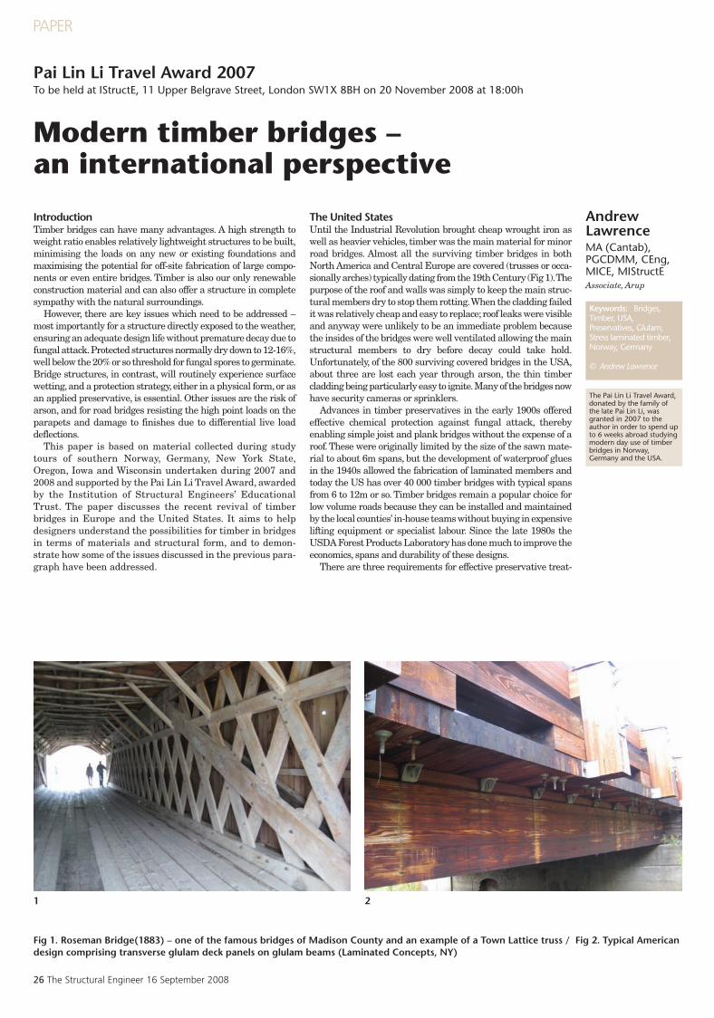
The United StatesUntil the Industrial Revolution brought cheap wrought iron aswell as heavier vehicles, timber was the main material for minorroad bridges. Almost all the surviving timber bridges in bothNorth America and Central Europe are covered (trusses or occa-sionally arches) typically dating from the 19th Century (Fig 1). Thepurpose of the roof and walls was simply to keep the main struc-tural members dry to stop them rotting. When the cladding failedit was relatively cheap and easy to replace; roof leaks were visibleand anyway were unlikely to be an immediate problem becausethe insides of the bridges were well ventilated allowing the mainstructural members to dry before decay could take hold.Unfortunately, of the 800 surviving covered bridges in the USA,about three are lost each year through arson, the thin timbercladding being particularly easy to ignite. Many of the bridges nowhave security cameras or sprinklers.
Advances in timber preservatives in the early 1900s offeredeffective chemical protection against fungal attack, therebyenabling simple joist and plank bridges without the expense of aroof. These were originally limited by the size of the sawn mate-rial to about 6m spans, but the development of waterproof gluesin the 1940s allowed the fabrication of laminated members andtoday the US has over 40 000 timber bridges with typical spansfrom 6 to 12m or so. Timber bridges remain a popular choice forlow volume roads because they can be installed and maintainedby the local counties’ in-house teams without buying in expensivelifting equipment or specialist labour. Since the late 1980s theUSDA Forest Products Laboratory has done much to improve theeconomics, spans and durability of these designs.
There are three requirements for effective preservative treat-
The Pai Lin Li Travel Award,donated by the family ofthe late Pai Lin Li, wasgranted in 2007 to theauthor in order to spend upto 6 weeks abroad studyingmodern day use of timberbridges in Norway,Germany and the USA.
SE18 Lawrence2 Pai lin li.qxp:Layout 1 10/9/08 15:19 Page 26
16 September 2008 The Structural Engineer 27
PAPER
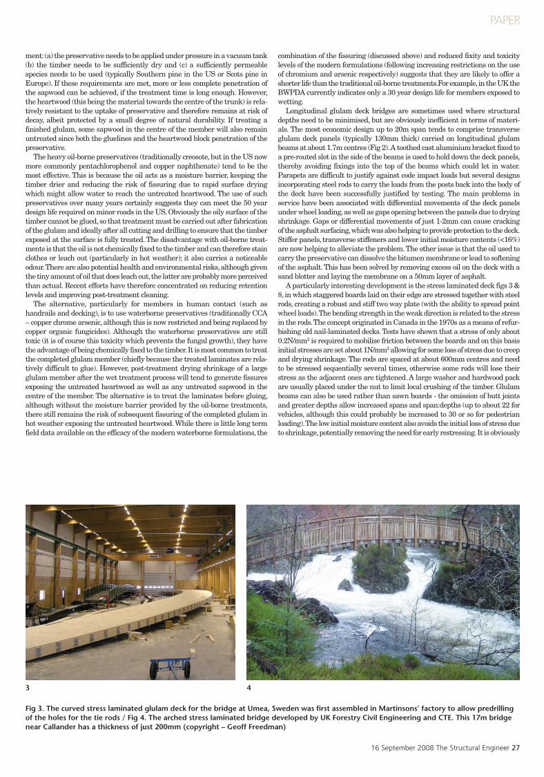
Fig 3. The curved stress laminated glulam deck for the bridge at Umea, Sweden was first assembled in Martinsons’ factory to allow predrillingof the holes for the tie rods / Fig 4. The arched stress laminated bridge developed by UK Forestry Civil Engineering and CTE. This 17m bridgenear Callander has a thickness of just 200mm (copyright – Geoff Freedman)
43
ment: (a) the preservative needs to be applied under pressure in a vacuum tank(b) the timber needs to be sufficiently dry and (c) a sufficiently permeablespecies needs to be used (typically Southern pine in the US or Scots pine inEurope). If these requirements are met, more or less complete penetration ofthe sapwood can be achieved, if the treatment time is long enough. However,the heartwood (this being the material towards the centre of the trunk) is rela-tively resistant to the uptake of preservative and therefore remains at risk ofdecay, albeit protected by a small degree of natural durability. If treating afinished glulam, some sapwood in the centre of the member will also remainuntreated since both the gluelines and the heartwood block penetration of thepreservative.
The heavy oil-borne preservatives (traditionally creosote, but in the US nowmore commonly pentachlorophenol and copper naphthenate) tend to be themost effective. This is because the oil acts as a moisture barrier, keeping thetimber drier and reducing the risk of fissuring due to rapid surface dryingwhich might allow water to reach the untreated heartwood. The use of suchpreservatives over many years certainly suggests they can meet the 50 yeardesign life required on minor roads in the US. Obviously the oily surface of thetimber cannot be glued, so that treatment must be carried out after fabricationof the glulam and ideally after all cutting and drilling to ensure that the timberexposed at the surface is fully treated. The disadvantage with oil-borne treat-ments is that the oil is not chemically fixed to the timber and can therefore stainclothes or leach out (particularly in hot weather); it also carries a noticeableodour. There are also potential health and environmental risks, although giventhe tiny amount of oil that does leach out, the latter are probably more perceivedthan actual. Recent efforts have therefore concentrated on reducing retentionlevels and improving post-treatment cleaning.
The alternative, particularly for members in human contact (such ashandrails and decking), is to use waterborne preservatives (traditionally CCA– copper chrome arsenic, although this is now restricted and being replaced bycopper organic fungicides). Although the waterborne preservatives are stilltoxic (it is of course this toxicity which prevents the fungal growth), they havethe advantage of being chemically fixed to the timber. It is most common to treatthe completed glulam member (chiefly because the treated laminates are rela-tively difficult to glue). However, post-treatment drying shrinkage of a largeglulam member after the wet treatment process will tend to generate fissuresexposing the untreated heartwood as well as any untreated sapwood in thecentre of the member. The alternative is to treat the laminates before gluing,although without the moisture barrier provided by the oil-borne treatments,there still remains the risk of subsequent fissuring of the completed glulam inhot weather exposing the untreated heartwood. While there is little long termfield data available on the efficacy of the modern waterborne formulations, the
combination of the fissuring (discussed above) and reduced fixity and toxicitylevels of the modern formulations (following increasing restrictions on the useof chromium and arsenic respectively) suggests that they are likely to offer ashorter life than the traditional oil-borne treatments.For example, in the UK theBWPDA currently indicates only a 30 year design life for members exposed towetting.
Longitudinal glulam deck bridges are sometimes used where structuraldepths need to be minimised, but are obviously inefficient in terms of materi-als. The most economic design up to 20m span tends to comprise transverseglulam deck panels (typically 130mm thick) carried on longitudinal glulambeams at about 1.7m centres (Fig 2). A toothed cast aluminium bracket fixed toa pre-routed slot in the side of the beams is used to hold down the deck panels,thereby avoiding fixings into the top of the beams which could let in water.Parapets are difficult to justify against code impact loads but several designsincorporating steel rods to carry the loads from the posts back into the body ofthe deck have been successfully justified by testing. The main problems inservice have been associated with differential movements of the deck panelsunder wheel loading, as well as gaps opening between the panels due to dryingshrinkage. Gaps or differential movements of just 1-2mm can cause crackingof the asphalt surfacing, which was also helping to provide protection to the deck.Stiffer panels, transverse stiffeners and lower initial moisture contents (<16%)are now helping to alleviate the problem. The other issue is that the oil used tocarry the preservative can dissolve the bitumen membrane or lead to softeningof the asphalt. This has been solved by removing excess oil on the deck with asand blotter and laying the membrane on a 50mm layer of asphalt.
A particularly interesting development is the stress laminated deck figs 3 &8, in which staggered boards laid on their edge are stressed together with steelrods, creating a robust and stiff two way plate (with the ability to spread pointwheel loads). The bending strength in the weak direction is related to the stressin the rods. The concept originated in Canada in the 1970s as a means of refur-bishing old nail-laminated decks. Tests have shown that a stress of only about0.2N/mm2 is required to mobilise friction between the boards and on this basisinitial stresses are set about 1N/mm2 allowing for some loss of stress due to creepand drying shrinkage. The rods are spaced at about 600mm centres and needto be stressed sequentially several times, otherwise some rods will lose theirstress as the adjacent ones are tightened. A large washer and hardwood packare usually placed under the nut to limit local crushing of the timber. Glulambeams can also be used rather than sawn boards - the omission of butt jointsand greater depths allow increased spans and span:depths (up to about 22 forvehicles, although this could probably be increased to 30 or so for pedestrianloading). The low initial moisture content also avoids the initial loss of stress dueto shrinkage, potentially removing the need for early restressing. It is obviously
SE18 Lawrence2 Pai lin li.qxp:Layout 1 10/9/08 15:19 Page 27
28 The Structural Engineer 16 September 2008
PAPER
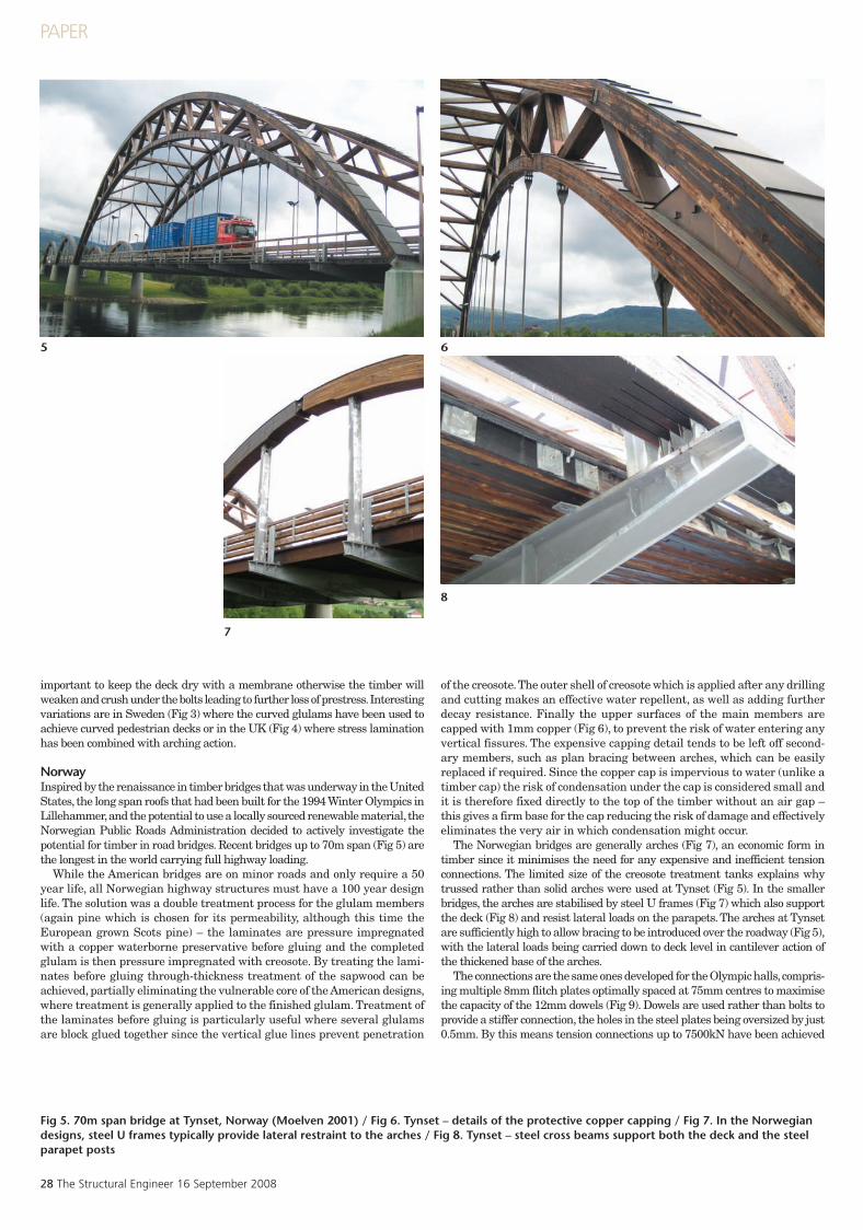
Fig 5. 70m span bridge at Tynset, Norway (Moelven 2001) / Fig 6. Tynset – details of the protective copper capping / Fig 7. In the Norwegiandesigns, steel U frames typically provide lateral restraint to the arches / Fig 8. Tynset – steel cross beams support both the deck and the steelparapet posts
7
8
5 6
important to keep the deck dry with a membrane otherwise the timber willweaken and crush under the bolts leading to further loss of prestress. Interestingvariations are in Sweden (Fig 3) where the curved glulams have been used toachieve curved pedestrian decks or in the UK (Fig 4) where stress laminationhas been combined with arching action.
NorwayInspired by the renaissance in timber bridges that was underway in the UnitedStates, the long span roofs that had been built for the 1994 Winter Olympics inLillehammer, and the potential to use a locally sourced renewable material, theNorwegian Public Roads Administration decided to actively investigate thepotential for timber in road bridges. Recent bridges up to 70m span (Fig 5) arethe longest in the world carrying full highway loading.
While the American bridges are on minor roads and only require a 50year life, all Norwegian highway structures must have a 100 year designlife. The solution was a double treatment process for the glulam members(again pine which is chosen for its permeability, although this time theEuropean grown Scots pine) – the laminates are pressure impregnatedwith a copper waterborne preservative before gluing and the completedglulam is then pressure impregnated with creosote. By treating the lami-nates before gluing through-thickness treatment of the sapwood can beachieved, partially eliminating the vulnerable core of the American designs,where treatment is generally applied to the finished glulam. Treatment ofthe laminates before gluing is particularly useful where several glulamsare block glued together since the vertical glue lines prevent penetration
of the creosote. The outer shell of creosote which is applied after any drillingand cutting makes an effective water repellent, as well as adding furtherdecay resistance. Finally the upper surfaces of the main members arecapped with 1mm copper (Fig 6), to prevent the risk of water entering anyvertical fissures. The expensive capping detail tends to be left off second-ary members, such as plan bracing between arches, which can be easilyreplaced if required. Since the copper cap is impervious to water (unlike atimber cap) the risk of condensation under the cap is considered small andit is therefore fixed directly to the top of the timber without an air gap –this gives a firm base for the cap reducing the risk of damage and effectivelyeliminates the very air in which condensation might occur.
The Norwegian bridges are generally arches (Fig 7), an economic form intimber since it minimises the need for any expensive and inefficient tensionconnections. The limited size of the creosote treatment tanks explains whytrussed rather than solid arches were used at Tynset (Fig 5). In the smallerbridges, the arches are stabilised by steel U frames (Fig 7) which also supportthe deck (Fig 8) and resist lateral loads on the parapets. The arches at Tynsetare sufficiently high to allow bracing to be introduced over the roadway (Fig 5),with the lateral loads being carried down to deck level in cantilever action ofthe thickened base of the arches.
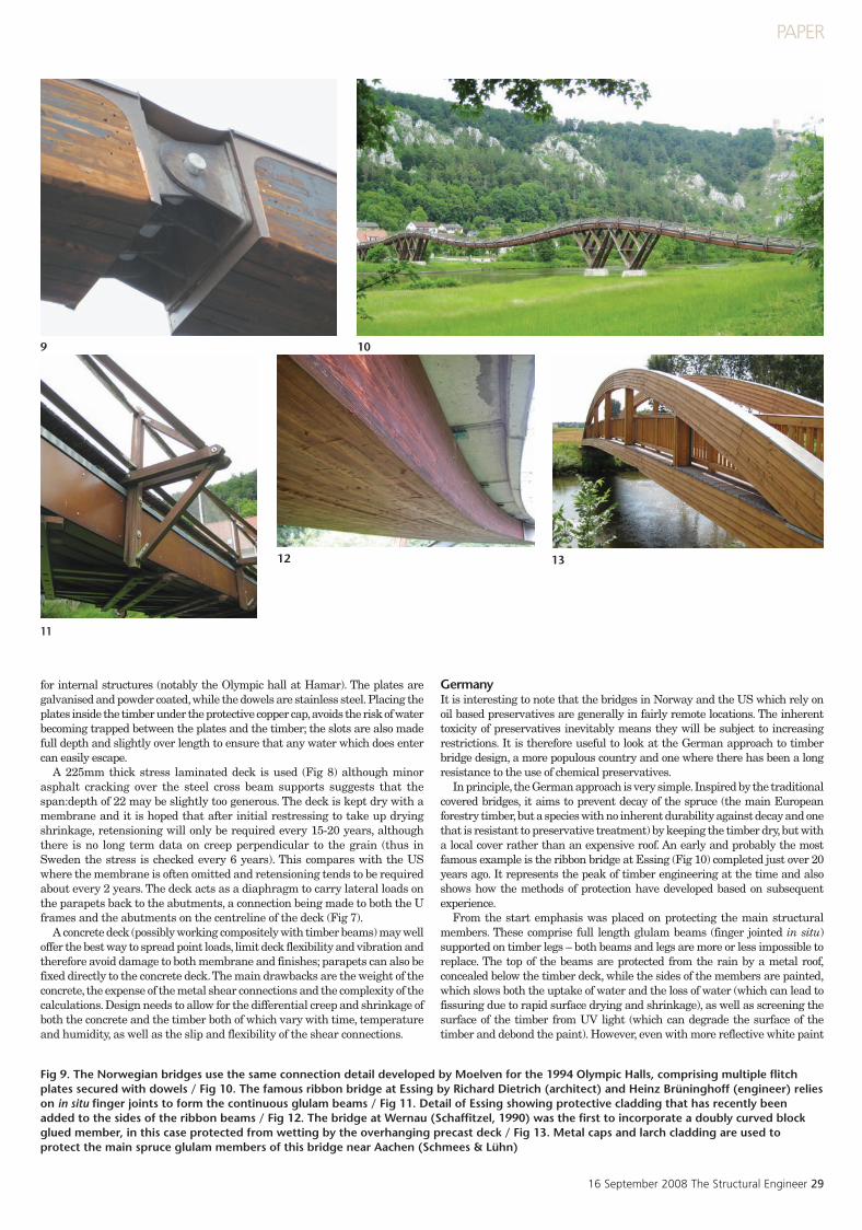
The connections are the same ones developed for the Olympic halls, compris-ing multiple 8mm flitch plates optimally spaced at 75mm centres to maximisethe capacity of the 12mm dowels (Fig 9). Dowels are used rather than bolts toprovide a stiffer connection, the holes in the steel plates being oversized by just0.5mm. By this means tension connections up to 7500kN have been achieved
SE18 Lawrence2 Pai lin li.qxp:Layout 1 10/9/08 15:19 Page 28
16 September 2008 The Structural Engineer 29
PAPER
Fig 9. The Norwegian bridges use the same connection detail developed by Moelven for the 1994 Olympic Halls, comprising multiple flitchplates secured with dowels / Fig 10. The famous ribbon bridge at Essing by Richard Dietrich (architect) and Heinz Brüninghoff (engineer) relieson in situ finger joints to form the continuous glulam beams / Fig 11. Detail of Essing showing protective cladding that has recently beenadded to the sides of the ribbon beams / Fig 12. The bridge at Wernau (Schaffitzel, 1990) was the first to incorporate a doubly curved blockglued member, in this case protected from wetting by the overhanging precast deck / Fig 13. Metal caps and larch cladding are used toprotect the main spruce glulam members of this bridge near Aachen (Schmees & Lühn)
for internal structures (notably the Olympic hall at Hamar). The plates aregalvanised and powder coated, while the dowels are stainless steel. Placing theplates inside the timber under the protective copper cap, avoids the risk of waterbecoming trapped between the plates and the timber; the slots are also madefull depth and slightly over length to ensure that any water which does entercan easily escape.
A 225mm thick stress laminated deck is used (Fig 8) although minorasphalt cracking over the steel cross beam supports suggests that thespan:depth of 22 may be slightly too generous. The deck is kept dry with amembrane and it is hoped that after initial restressing to take up dryingshrinkage, retensioning will only be required every 15-20 years, althoughthere is no long term data on creep perpendicular to the grain (thus inSweden the stress is checked every 6 years). This compares with the USwhere the membrane is often omitted and retensioning tends to be requiredabout every 2 years. The deck acts as a diaphragm to carry lateral loads onthe parapets back to the abutments, a connection being made to both the Uframes and the abutments on the centreline of the deck (Fig 7).
A concrete deck (possibly working compositely with timber beams) may welloffer the best way to spread point loads, limit deck flexibility and vibration andtherefore avoid damage to both membrane and finishes; parapets can also befixed directly to the concrete deck. The main drawbacks are the weight of theconcrete, the expense of the metal shear connections and the complexity of thecalculations. Design needs to allow for the differential creep and shrinkage ofboth the concrete and the timber both of which vary with time, temperatureand humidity, as well as the slip and flexibility of the shear connections.
GermanyIt is interesting to note that the bridges in Norway and the US which rely onoil based preservatives are generally in fairly remote locations. The inherenttoxicity of preservatives inevitably means they will be subject to increasingrestrictions. It is therefore useful to look at the German approach to timberbridge design, a more populous country and one where there has been a longresistance to the use of chemical preservatives.
In principle, the German approach is very simple. Inspired by the traditionalcovered bridges, it aims to prevent decay of the spruce (the main Europeanforestry timber, but a species with no inherent durability against decay and onethat is resistant to preservative treatment) by keeping the timber dry, but witha local cover rather than an expensive roof. An early and probably the mostfamous example is the ribbon bridge at Essing (Fig 10) completed just over 20years ago. It represents the peak of timber engineering at the time and alsoshows how the methods of protection have developed based on subsequentexperience.
From the start emphasis was placed on protecting the main structuralmembers. These comprise full length glulam beams (finger jointed in situ)supported on timber legs – both beams and legs are more or less impossible toreplace. The top of the beams are protected from the rain by a metal roof,concealed below the timber deck, while the sides of the members are painted,which slows both the uptake of water and the loss of water (which can lead tofissuring due to rapid surface drying and shrinkage), as well as screening thesurface of the timber from UV light (which can degrade the surface of thetimber and debond the paint). However, even with more reflective white paint
11
1312
9 10
SE18 Lawrence2 Pai lin li.qxp:Layout 1 10/9/08 15:19 Page 29
30 The Structural Engineer 16 September 2008
PAPER
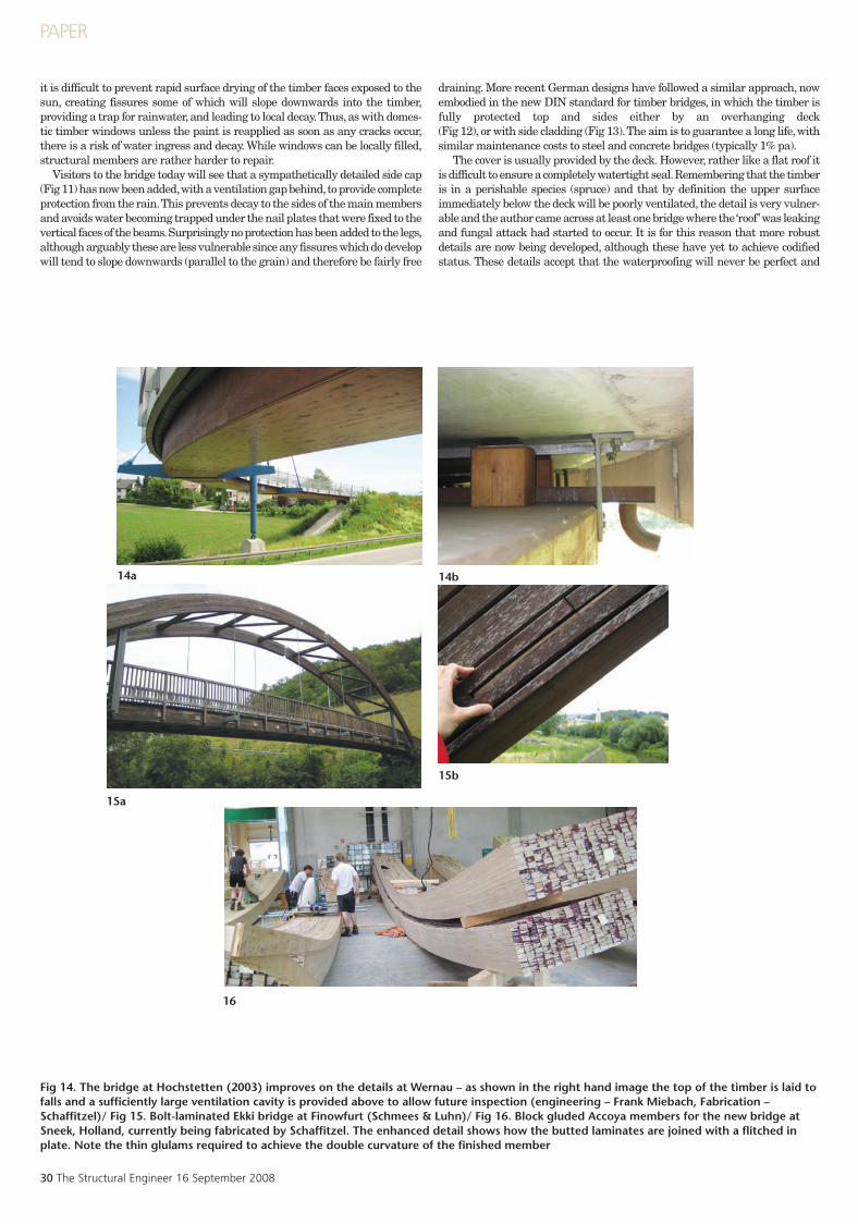
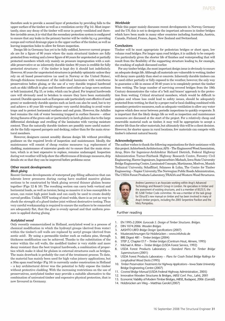
Fig 14. The bridge at Hochstetten (2003) improves on the details at Wernau – as shown in the right hand image the top of the timber is laid tofalls and a sufficiently large ventilation cavity is provided above to allow future inspection (engineering – Frank Miebach, Fabrication –Schaffitzel)/ Fig 15. Bolt-laminated Ekki bridge at Finowfurt (Schmees & Luhn)/ Fig 16. Block gluded Accoya members for the new bridge atSneek, Holland, currently being fabricated by Schaffitzel. The enhanced detail shows how the butted laminates are joined with a flitched inplate. Note the thin glulams required to achieve the double curvature of the finished member
it is difficult to prevent rapid surface drying of the timber faces exposed to thesun, creating fissures some of which will slope downwards into the timber,providing a trap for rainwater, and leading to local decay. Thus, as with domes-tic timber windows unless the paint is reapplied as soon as any cracks occur,there is a risk of water ingress and decay. While windows can be locally filled,structural members are rather harder to repair.
Visitors to the bridge today will see that a sympathetically detailed side cap(Fig 11) has now been added, with a ventilation gap behind, to provide completeprotection from the rain. This prevents decay to the sides of the main membersand avoids water becoming trapped under the nail plates that were fixed to thevertical faces of the beams. Surprisingly no protection has been added to the legs,although arguably these are less vulnerable since any fissures which do developwill tend to slope downwards (parallel to the grain) and therefore be fairly free
draining. More recent German designs have followed a similar approach, nowembodied in the new DIN standard for timber bridges, in which the timber isfully protected top and sides either by an overhanging deck (Fig 12), or with side cladding (Fig 13). The aim is to guarantee a long life, withsimilar maintenance costs to steel and concrete bridges (typically 1% pa).
The cover is usually provided by the deck. However, rather like a flat roof itis difficult to ensure a completely watertight seal. Remembering that the timberis in a perishable species (spruce) and that by definition the upper surfaceimmediately below the deck will be poorly ventilated, the detail is very vulner-able and the author came across at least one bridge where the ‘roof’ was leakingand fungal attack had started to occur. It is for this reason that more robustdetails are now being developed, although these have yet to achieve codifiedstatus. These details accept that the waterproofing will never be perfect and
14b
15b
15a
16
14a
SE18 Lawrence2 Pai lin li.qxp:Layout 1 10/9/08 15:19 Page 30
16 September 2008 The Structural Engineer 31
PAPER
therefore seek to provide a second layer of protection by providing falls to theupper surface of the timber as well as a ventilation cavity (Fig 14). Most impor-tantly, since any decay of the timber will occur in poorly ventilated and there-fore invisible areas, it is vital that the secondary protection system is configuredto ensure that any leaks in the primary barrier will be visible by, e.g. providingsumps and vertical drainage pipes in the upper surface of the timber, as well asleaving inspection holes to allow for future inspection.
Design life in Germany has yet to be fully codified, however current propos-als are for a figure of 80 years where the main structural timbers are fullyprotected from wetting and a lower figure of 40 years for unprotected or partiallyprotected members which rely mainly on pressure impregnation with a suit-able preservative or an inherently durable timber. 80 years is credible for fullyprotected structures – if the timber is kept dry it should last indefinitely.However, 40 years for unprotected structures is probably optimistic unless theyrely on oil based preservatives (as used in Norway or the United States),through-thickness treatment of the individual laminates with waterbornepreservatives before gluing, or the use of a very durable tropical hardwoodsuch as ekki (difficult to glue and therefore used either as large sawn sectionsor bolt laminated, Fig 15, or iroko, which can be glued. For tropical hardwoodscare will obviously need to betaken to ensure they have been sustainablysourced. Durable species such as European oak (particularly cost effective if usedgreen) or moderately durable species such as larch can also be used, but to tryand achieve a 40 year life would require very careful detailing to avoid watertraps and to protect horizontal surfaces and end grain. However, the Achillesheel remains the risk of water becoming trapped in surface fissures – eitherdrying fissures of the green oak or (particularly in larch glulam) due to the largedifferential shrinkage and swelling of the laminates with varying moisturecontent. Thus the naturally durable timbers are possibly more useful materi-als for the fully exposed parapets and decking, rather than for the main struc-tural members.
However, designers cannot sensibly discuss design life without providingguidance on the required levels of inspection and maintenance. Ideally, themaintenance will consist of cheap routine measures (e.g. replacement ofcladding, maintenance of rainwater goods etc) to ensure that the main struc-ture, which is at best expensive to replace, remains undamaged. Inspectionduring wet weather will help show the effectiveness of drainage measures, dripdetails etc so that they can be improved before problems occur.
Other recent developmentsBlock gluingRecent German developments of waterproof gap filling adhesives that cantolerate lower pressures during curing have enabled massive glulamsections to be constructed by block gluing several thinner glulam beamstogether (Figs 12 & 16). The resulting section can carry both vertical andhorizontal loads, as well as torsion; being so massive it is less susceptible toarson, can resist high point loads and can easily be used to create doublycurved profiles. Unlike NDT testing of steel welds, there is as yet no way tocheck the strength of a glued timber joint without destructive testing. Thusvery careful workmanship is required to ensure the surfaces to be connectedare adequately flat, that the glue is evenly spread and that uniform pres-sure is applied during gluing.
Acetylated woodOnly recently commercialised in Holland, acetylated wood is a process ofchemical modification in which the hydroxyl groups (derived from water)within the timber’s cell walls are replaced by acetyl groups (derived fromacetic acid). By using a permeable timber such as radiata pine, throughthickness modification can be achieved. Thanks to the substitution of thewater within the cell walls, the modified timber is very stable and moredecay resistant than the best tropical hardwoods, a combination of proper-ties which make it ideal for glulam in external structures such as bridges.The main drawback is probably the cost of the treatment process. To date,the material has mainly been used for high value joinery applications, buta 30m span road bridge (Fig 16) is currently under construction in Holland– a key architectural driver was the potential to fully expose the timberwithout protective cladding. With the increasing restrictions on the use ofpreservatives, acetylated timber may provide a suitable alternative to thecombination of untreated timber and expensive physical protection, that isnow favoured in Germany.
WorldwideWhile this paper mainly discusses recent developments in Norway, Germanyand the US, this is not to denigrate the important advances in timber bridgeswhich have been made in many other countries including Australia, Austria,Canada, Finland, France, Japan, New Zealand and Switzerland.
ConclusionsTimber will be most appropriate for pedestrian bridges or short span, lowvolume road bridges. For longer span road bridges, it is unlikely to be competi-tive particularly given the shorter life of finishes and waterproofing that willresult from the flexibility of the supporting structure leading to, for example,the cracking of asphalt discussed earlier.
For any timber bridge, the most important design issue is obviously to ensurean adequate design life. Although all materials are vulnerable to wetting, timberwill decay more quickly than steel or concrete. Inherently durable timbers canbe used either partially or fully exposed to the weather, however, the only wayto guarantee a life in excess of 30-40 years is to completely protect the timberfrom wetting. The large number of surviving covered bridges from the 19thCentury demonstrates the value of a ‘belt and braces’ approach to the protec-tion from wetting. Critical structural members, which would be difficult toreplace and whose loss could lead to safety issues, should be adequatelyprotected from wetting, be that by a proper roof or local cladding combined withsecondary protective measures, such as adequate ventilation to allow any wateringress which does occur between periodic inspections to quickly evaporate. Itis important that the likely design life as well as inspection and maintenancemeasures are discussed at the start of the project. For a relatively cheap andrenewable material such as timber, it may well be appropriate to accept ashorter life than for other materials, but ultimately this will be a client decision.However, for shorter spans in rural locations, few materials can compete withtimber’s inherent natural beauty.
AcknowledgmentsThe author wishes to thank the following organisations for their assistance withthis project: Achterbosch Architectuur, APA – The Engineered Wood Association,Arup, Büro für Ingenieur-Architektur Richard Dietrich, Federal HighwayAdministration Turner-Fairbank Highway Research Centre, Forestry CivilEngineering, Harrer Ingenieure, Ingenieurbüro Miebach, Iowa State UniversityBridge Engineering Centre, Laminated Concepts, Martinsons, Moelven, MunichTechnical University, Schaffitzel, Schmees & Lühn, The Centre for TimberEngineering – Napier University, The Norwegian Public Roads Administration,The USDA Forest Products Laboratory, TRADA and Western Wood Structures.
Andrew Lawrence is an Associate working within Arup’s AdvancedTechnology and Research Group in London. He specialises in timber andthe assessment of existing structures, and is a member of B525/5, the BS 5268 Timber Code committee. He was a member of the task groupfor IStructE’s new manual on timber and has been involved in many ofArup’s timber projects, including the 2005 Serpentine Pavilion and theMetz Pompidou.
1. EN 1995-2:2004: Eurocode 5. Design of Timber Structures. Bridges.2. DIN 1074:2006: Wooden Bridges3. AASHTO LRFD Bridge Design Specifications (2007)4. Musterzeichnungen für Holzbrücken – www.infoholz.de5. BRE Digest 481 – Timber bridges (2004)6. STEP 2, Chapter E17 – Timber bridges (Centrum Hout, Almere, 1995)7. Michael A. Ritter – Timber Bridges (USDA Forest Service, 1992)8. USDA Forest Products Laboratory – Standard Plans for Timber Bridge
Superstructures (2001)9. USDA Forest Products Laboratory – Plans for Crash-Tested Bridge Railings for
Longitudinal Wood Decks (1995)10. Timber Preservation Treatments for Highway Applications – Iowa State University
Bridge Engineering Centre (2007)11. Covered Bridge Manual (USDA Federal Highway Administration, 2005)12. Innovative Wooden Structures & Bridges, IABSE Conf. Proc., Lahti, 200113. Economic Viability of Modern Timber Bridges, IABSE, Budapest, 2006 (Gerold)14. Holzbrücken am Weg – Matthias Gerold (2007)
Further reading
SE18 Lawrence2 Pai lin li.qxp:Layout 1 10/9/08 15:19 Page 31