

Modern Test and Measure: February 2016
30
February 2016 ∨ ∨ Keysight Targets Power Arena Oscilloscope Highlights from Embedded World USB Type-C Power Delivery Interview with Kari Fauber GM of the Power & Energy Division at Keysight Technologies Testing Tech Optimizes Efficiency in Alternative Energy Applications
-
Upload
eeweb-magazines -
Category
Documents
-
view
216 -
download
0
description
Keysight Targets Power Arena: Testing Technology Optimizes Efficiency in Alternative Energy Applications
Transcript of Modern Test and Measure: February 2016

February 2016
∨∨
Keysight Targets Power Arena
Oscilloscope Highlights from Embedded World
USB Type-C Power Delivery
Interview with Kari Fauber GM of the Power & Energy Division at Keysight Technologies
Testing Tech Optimizes Efficiency in Alternative
Energy Applications

Modern Test & Measure CONTENTS
4
1610
24
EEWeb
EDITORIAL STAFFContent EditorAlex Maddalena [email protected]
Digital Content ManagerHeather Hamilton [email protected] Tel | 208-639-6485
Global Creative DirectorNicolas Perner [email protected]
Graphic DesignerCarol Smiley [email protected]
Audience DevelopmentClaire Hellar [email protected]
Register at EEWebhttp://www.eeweb.com/register/
Published byAspenCore
950 West Bannock Suite 450
Boise, Idaho 83702 Tel | 208-639-6464
Victor Alejandro Gao General Manager Executive Publisher
Cody Miller Global Media Director
Group Publisher
NEWSWIRE
Oscilloscope Highlights from Embedded World and New Test Equipment Innovations
TECH REPORTS
A Look at USB Type-C and Power Delivery
How to Calibrate RTD Temperature Devices
INDUSTRY INTERVIEW
Keysight Targets Power IndustryInterview with Kari Fauber – GM of the Power & Energy Division at Keysight Technologies
24
16
4
10

Highland Technology
4
Modern Test & Measure
8-channel Waveform Playback
Source: Highland Technology
Newswire
The Highland Technology model P350 “Wayback Machine” is a compact Ethernet-based waveform playback unit designed specifically for aerospace simulation testing. It provides eight analog outputs that can be used independently or synchronously. In Playback mode, any P350 channel can store and play multi-gigabyte user waveform files, with flexible playback rates, summing, filtering, scaling/offset, and phase/timeshift provisions. Any channel can also operate in Wavetable mode, playing repetitive standard or arbitrary waveforms.
Two analog inputs and two random noise generators are available for modulation or summing. Programming features allow accurate, glitch-free, low-jitter simulation of complex waveforms as might be generated by sensors on jet engines or other complex machines.
FEATURES
• Eight channels of independent or synchronized 16-bit waveform generation
• Two ADC analog inputs for summing or modulation
• File playback and repetitive arbitrary wave generation modes
• 32GB of internal waveform file storage
• Realtime programmable sample rates, amplitudes, phase, time shift
• Two bandwidth-programmable Gaussian noise generators
• Includes modulation, filtering, channel summing, noise generation
• Multi-box phase locking and waveform synchronizations
• Embedded Linux with Gbit Ethernet and USB interfaces
• Includes built-in self-test and signal monitor connectors
Oscilloscope Highlights at Embedded World 2016
Source: Rohde & Schwarz
At embedded world 2016, Rohde & Schwarz will again showcase its ever-expanding oscilloscope portfolio. At the Rohde & Schwarz booth, visitors can get a first-hand look at the new R&S Scope Rider, the first handheld oscilloscope to offer the functionality and user experience of a state-of-the-art lab oscilloscope.
One of the highlights at embedded world 2016 in Nuremberg will be the new R&S Scope Rider, the first portable oscilloscope for mobile use with the functionality of a lab instrument. The R&S Scope Rider packs five test instruments into a compact format: a lab oscilloscope, logic analyzer, protocol analyzer, data logger and digital multimeter. Its robust design makes it perfect for mobile installation and maintenance work. The fully insulated
instrument meets measurement category CAT IV requirements and can be used to perform measurements at the source of low-voltage installations up to 600 V.
Additional trade show highlights include the new entry-level R&S HMO1202 mixed signal oscilloscope that offers outstanding performance at an exceptional price. The R&S RTM, R&S RTE and R&S RTO oscilloscope families and accessories will also be represented. Featuring a range of trigger and decoding options as well as options for compliance testing, these Rohde & Schwarz oscilloscopes provide valuable support in design verification, commissioning, debugging and compliance testing for a wide range of users in areas ranging from embedded design and mobile communications to automotive.

Rohde & Schwwarz
5
NEWSWIRE
8-channel Waveform Playback
Source: Highland Technology
Newswire
The Highland Technology model P350 “Wayback Machine” is a compact Ethernet-based waveform playback unit designed specifically for aerospace simulation testing. It provides eight analog outputs that can be used independently or synchronously. In Playback mode, any P350 channel can store and play multi-gigabyte user waveform files, with flexible playback rates, summing, filtering, scaling/offset, and phase/timeshift provisions. Any channel can also operate in Wavetable mode, playing repetitive standard or arbitrary waveforms.
Two analog inputs and two random noise generators are available for modulation or summing. Programming features allow accurate, glitch-free, low-jitter simulation of complex waveforms as might be generated by sensors on jet engines or other complex machines.
FEATURES
• Eight channels of independent or synchronized 16-bit waveform generation
• Two ADC analog inputs for summing or modulation
• File playback and repetitive arbitrary wave generation modes
• 32GB of internal waveform file storage
• Realtime programmable sample rates, amplitudes, phase, time shift
• Two bandwidth-programmable Gaussian noise generators
• Includes modulation, filtering, channel summing, noise generation
• Multi-box phase locking and waveform synchronizations
• Embedded Linux with Gbit Ethernet and USB interfaces
• Includes built-in self-test and signal monitor connectors
Oscilloscope Highlights at Embedded World 2016
Source: Rohde & Schwarz
At embedded world 2016, Rohde & Schwarz will again showcase its ever-expanding oscilloscope portfolio. At the Rohde & Schwarz booth, visitors can get a first-hand look at the new R&S Scope Rider, the first handheld oscilloscope to offer the functionality and user experience of a state-of-the-art lab oscilloscope.
One of the highlights at embedded world 2016 in Nuremberg will be the new R&S Scope Rider, the first portable oscilloscope for mobile use with the functionality of a lab instrument. The R&S Scope Rider packs five test instruments into a compact format: a lab oscilloscope, logic analyzer, protocol analyzer, data logger and digital multimeter. Its robust design makes it perfect for mobile installation and maintenance work. The fully insulated
instrument meets measurement category CAT IV requirements and can be used to perform measurements at the source of low-voltage installations up to 600 V.
Additional trade show highlights include the new entry-level R&S HMO1202 mixed signal oscilloscope that offers outstanding performance at an exceptional price. The R&S RTM, R&S RTE and R&S RTO oscilloscope families and accessories will also be represented. Featuring a range of trigger and decoding options as well as options for compliance testing, these Rohde & Schwarz oscilloscopes provide valuable support in design verification, commissioning, debugging and compliance testing for a wide range of users in areas ranging from embedded design and mobile communications to automotive.

Keysight Technologies
6
Modern Test & Measure
Wireless Test Set with WaveStudio Spectrum Analyzer with Digital IF Tecnology
Source: Keysight Technologies
Source: Siglent Technologies
Keysight Technologies, Inc. announced that the Keysight UXM Wireless Test Set is now fully integrated and supported by WaveStudio, MVG’s OTA dedicated measurement software suite. As an integral part of MVG’s OTA measurement solution, the UXM has been used to provide support for Carrier Aggregation; an important LTE-A feature that requires advanced test and measurement. Users can now test the performance of the very latest wireless devices in a radiated environment efficiently and with confidence.
MVG (previously SATIMO), a long established Keysight Solution Partner, has provided CTIA approved OTA test solutions to network operators, device developers and test labs for over 30 years.
“By integrating the UXM into WaveStudio, we can, together with Keysight, offer our customers a proven measurement solution that evolves with their needs,” said Nicolas Gross, Director of Applications at MVG. “With the constant and rapid progress in wireless development, device and network performance matter. The integrated solution ultimately equates to an improved user experience, which benefits device makers and network operators alike.”
“We’re delighted that our continued collaboration with MVG has yielded another success,” said Satish Dhanasekaran, general manager of Keysight’s Mobile Broadband Operation. “MVG continues to exploit the power and versatility of the UXM platform by providing cutting edge capability to our mutual customers.”
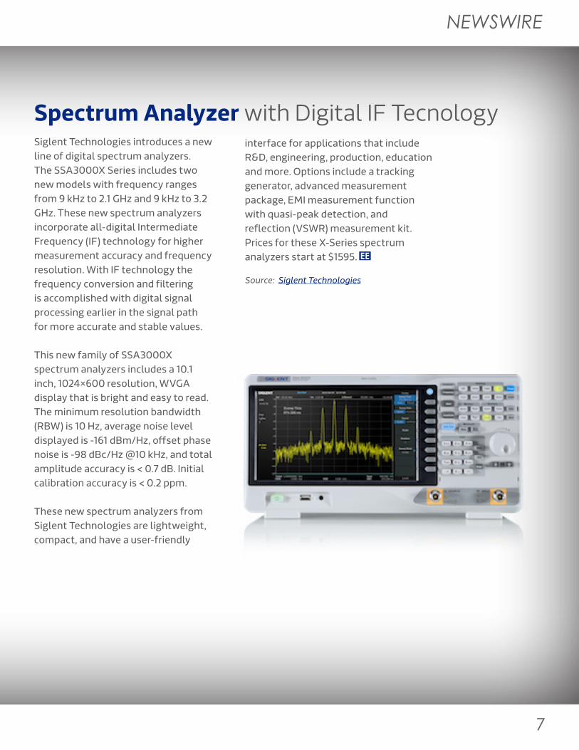
Siglent Technologies introduces a new line of digital spectrum analyzers. The SSA3000X Series includes two new models with frequency ranges from 9 kHz to 2.1 GHz and 9 kHz to 3.2 GHz. These new spectrum analyzers incorporate all-digital Intermediate Frequency (IF) technology for higher measurement accuracy and frequency resolution. With IF technology the frequency conversion and filtering is accomplished with digital signal processing earlier in the signal path for more accurate and stable values.
This new family of SSA3000X spectrum analyzers includes a 10.1 inch, 1024×600 resolution, WVGA display that is bright and easy to read. The minimum resolution bandwidth (RBW) is 10 Hz, average noise level displayed is -161 dBm/Hz, offset phase noise is -98 dBc/Hz @10 kHz, and total amplitude accuracy is < 0.7 dB. Initial calibration accuracy is < 0.2 ppm.
These new spectrum analyzers from Siglent Technologies are lightweight, compact, and have a user-friendly
interface for applications that include R&D, engineering, production, education and more. Options include a tracking generator, advanced measurement package, EMI measurement function with quasi-peak detection, and reflection (VSWR) measurement kit. Prices for these X-Series spectrum analyzers start at $1595.
Siglent Technologies
7
NEWSWIRE
Wireless Test Set with WaveStudio Spectrum Analyzer with Digital IF Tecnology
Source: Keysight Technologies
Source: Siglent Technologies
Keysight Technologies, Inc. announced that the Keysight UXM Wireless Test Set is now fully integrated and supported by WaveStudio, MVG’s OTA dedicated measurement software suite. As an integral part of MVG’s OTA measurement solution, the UXM has been used to provide support for Carrier Aggregation; an important LTE-A feature that requires advanced test and measurement. Users can now test the performance of the very latest wireless devices in a radiated environment efficiently and with confidence.
MVG (previously SATIMO), a long established Keysight Solution Partner, has provided CTIA approved OTA test solutions to network operators, device developers and test labs for over 30 years.
“By integrating the UXM into WaveStudio, we can, together with Keysight, offer our customers a proven measurement solution that evolves with their needs,” said Nicolas Gross, Director of Applications at MVG. “With the constant and rapid progress in wireless development, device and network performance matter. The integrated solution ultimately equates to an improved user experience, which benefits device makers and network operators alike.”
“We’re delighted that our continued collaboration with MVG has yielded another success,” said Satish Dhanasekaran, general manager of Keysight’s Mobile Broadband Operation. “MVG continues to exploit the power and versatility of the UXM platform by providing cutting edge capability to our mutual customers.”
Siglent Technologies introduces a new line of digital spectrum analyzers. The SSA3000X Series includes two new models with frequency ranges from 9 kHz to 2.1 GHz and 9 kHz to 3.2 GHz. These new spectrum analyzers incorporate all-digital Intermediate Frequency (IF) technology for higher measurement accuracy and frequency resolution. With IF technology the frequency conversion and filtering is accomplished with digital signal processing earlier in the signal path for more accurate and stable values.
This new family of SSA3000X spectrum analyzers includes a 10.1 inch, 1024×600 resolution, WVGA display that is bright and easy to read. The minimum resolution bandwidth (RBW) is 10 Hz, average noise level displayed is -161 dBm/Hz, offset phase noise is -98 dBc/Hz @10 kHz, and total amplitude accuracy is < 0.7 dB. Initial calibration accuracy is < 0.2 ppm.
These new spectrum analyzers from Siglent Technologies are lightweight, compact, and have a user-friendly
interface for applications that include R&D, engineering, production, education and more. Options include a tracking generator, advanced measurement package, EMI measurement function with quasi-peak detection, and reflection (VSWR) measurement kit. Prices for these X-Series spectrum analyzers start at $1595.

http://www.keysight.com/find/infiniivision-knowledge

10
Modern Test & Measure
C A Look at USB Type-C and Power Delivery
By David Maliniak, Teledyne LeCroy
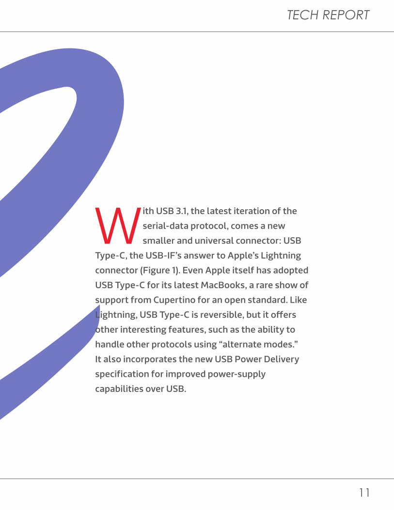
With USB 3.1, the latest iteration of the
serial-data protocol, comes a new
smaller and universal connector: USB
Type-C, the USB-IF’s answer to Apple’s Lightning
connector (Figure 1). Even Apple itself has adopted
USB Type-C for its latest MacBooks, a rare show of
support from Cupertino for an open standard. Like
Lightning, USB Type-C is reversible, but it offers
other interesting features, such as the ability to
handle other protocols using “alternate modes.”
It also incorporates the new USB Power Delivery
specification for improved power-supply
capabilities over USB.
TECH REPORT
11
C A Look at USB Type-C and Power Delivery
By David Maliniak, Teledyne LeCroy
With USB 3.1, the latest iteration of the
serial-data protocol, comes a new
smaller and universal connector: USB
Type-C, the USB-IF’s answer to Apple’s Lightning
connector (Figure 1). Even Apple itself has adopted
USB Type-C for its latest MacBooks, a rare show of
support from Cupertino for an open standard. Like
Lightning, USB Type-C is reversible, but it offers
other interesting features, such as the ability to
handle other protocols using “alternate modes.”
It also incorporates the new USB Power Delivery
specification for improved power-supply
capabilities over USB.

12
Modern Test & Measure
CUSB Type-C brings some new and different test challenges due to changes in link configuration and cable detection, among other things. Much of the new complexity comes from the amalgamation of two complementary USB-IF specifications: the Power Delivery 2.0 spec and the USB Type-C spec itself.
The two specifications have become linked together, but this wasn’t initially the intent. The higher voltage handling of PD 2.0 was intended for application in legacy USB connectors using FSK signaling. In the meantime, though, interest in FSK signaling vanished. Those interested in implementing the Power Delivery specification have migrated to USB Type-C, with emphasis on very thin notebooks, tablets, and smart phones. Another appealing aspect of the Type-C connector is its universality, which lends itself to the trend toward reduction of e-waste. The mobile market, in particular, is more than ready to settle on a universal charging cable. As to what is included in the Power Delivery and Type-C specifications, the former defines elements such as power delivery discovery, negotiation, and role swapping; biphase mark coding
(BMC) and frequency-shift keying (FSK) signaling; and commands for the afore-mentioned alternate modes. The Type-C specification encompasses mechanical and electrical (physical-layer) parameters; the specs for active cables (electronically marked cables with signal-conditioning circuits); and,
Figure 1. The USB Type-C connector alongside its Micro-B counterpart
Figure 2. A comparison of the Type-C and legacy USB receptacles
in a subsection called Functional Extensions, the logical state machines for alternate modes. Unfortunately, at this time there are no plans to merge these two complementary specifications, which would clear up lots of confusion for developers.
LEGACY USB 3.0 VS. TYPE C RECEPTACLE
USB 3.1 TYPE-C
USB 3.1 MICRO-B

TECH REPORT
13
CUSB Type-C brings some new and different test challenges due to changes in link configuration and cable detection, among other things. Much of the new complexity comes from the amalgamation of two complementary USB-IF specifications: the Power Delivery 2.0 spec and the USB Type-C spec itself.
The two specifications have become linked together, but this wasn’t initially the intent. The higher voltage handling of PD 2.0 was intended for application in legacy USB connectors using FSK signaling. In the meantime, though, interest in FSK signaling vanished. Those interested in implementing the Power Delivery specification have migrated to USB Type-C, with emphasis on very thin notebooks, tablets, and smart phones. Another appealing aspect of the Type-C connector is its universality, which lends itself to the trend toward reduction of e-waste. The mobile market, in particular, is more than ready to settle on a universal charging cable. As to what is included in the Power Delivery and Type-C specifications, the former defines elements such as power delivery discovery, negotiation, and role swapping; biphase mark coding
(BMC) and frequency-shift keying (FSK) signaling; and commands for the afore-mentioned alternate modes. The Type-C specification encompasses mechanical and electrical (physical-layer) parameters; the specs for active cables (electronically marked cables with signal-conditioning circuits); and,
Figure 1. The USB Type-C connector alongside its Micro-B counterpart
Figure 2. A comparison of the Type-C and legacy USB receptacles
in a subsection called Functional Extensions, the logical state machines for alternate modes. Unfortunately, at this time there are no plans to merge these two complementary specifications, which would clear up lots of confusion for developers.
LEGACY USB 3.0 VS. TYPE C RECEPTACLE
USB 3.1 TYPE-C
USB 3.1 MICRO-B

14
Modern Test & Measure
CAny discussion of the Power Delivery spec has to start with the Type-C receptacle pinout. To make the cable “flippable,” the receptacle has a redundant set of pins, one row being the mirror image of the other. If you compare the Type-C receptacle to a legacy USB 3.0 receptacle, the legacy pins map to the new pins in the upper row (A) of the Type-C receptacle, with a redundant row of pins on the bottom (B) that won’t be used for USB (Figure 2). So if you were to unplug a Type-C cable and flip it over before plugging it in again, you’d be making the same connections, only to a different physical pin. Thus, the
cable plug is “flippable,” but it’s the receptacle’s design that makes it so.
Also of interest is a head-on view of the Type-C receptacle along with the Type-C cable plug (Figure 3). The pinouts look similar enough, but there is one big difference that is important to understanding how Type-C works: Only the receptacle side has the fully redundant set of pins. The cable, unlike the receptacle, is not symmetrical. Referring again to Figure 3, pin A5 of the Type-C cable plug always carries
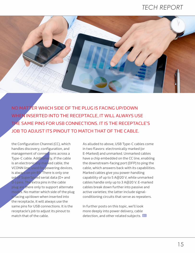
the Configuration Channel (CC), which handles discovery, configuration, and management of connections across a Type-C cable. Additionally, if the cable is an electronically marked cable, the VCONN line, used for powering devices, is always on pin B5. There is only one set of SuperSpeed serial data (D+ and D-) pins. The extra pins in the cable plug are there only to support alternate modes. No matter which side of the plug is facing up/down when inserted into the receptacle, it will always use the same pins for USB connections. It is the receptacle’s job to adjust its pinout to match that of the cable.
Figure 3. Comparing the Type-C receptacle and Type-C plug
NO MATTER WHICH SIDE OF THE PLUG IS FACING UP/DOWN
WHEN INSERTED INTO THE RECEPTACLE, IT WILL ALWAYS USE
THE SAME PINS FOR USB CONNECTIONS. IT IS THE RECEPTACLE’S
JOB TO ADJUST ITS PINOUT TO MATCH THAT OF THE CABLE.LEGACY USB 3.0 VS. TYPE C RECEPTACLE
As alluded to above, USB Type-C cables come in two flavors: electronically marked (or E-Marked) and unmarked. Unmarked cables have a chip embedded on the CC line, enabling the downstream-facing port (DFP) to ping the cable, which answers back with its capabilities. Marked cables give you power-handling capability of up to 5 A@20 V, while unmarked cables handle only up to 3 A@20 V. E-marked cables break down further into passive and active varieties; the latter include signal-conditioning circuits that serve as repeaters. In further posts on this topic, we’ll look more deeply into power delivery, cable detection, and other related subjects.
TECH REPORT
15
CAny discussion of the Power Delivery spec has to start with the Type-C receptacle pinout. To make the cable “flippable,” the receptacle has a redundant set of pins, one row being the mirror image of the other. If you compare the Type-C receptacle to a legacy USB 3.0 receptacle, the legacy pins map to the new pins in the upper row (A) of the Type-C receptacle, with a redundant row of pins on the bottom (B) that won’t be used for USB (Figure 2). So if you were to unplug a Type-C cable and flip it over before plugging it in again, you’d be making the same connections, only to a different physical pin. Thus, the
cable plug is “flippable,” but it’s the receptacle’s design that makes it so.
Also of interest is a head-on view of the Type-C receptacle along with the Type-C cable plug (Figure 3). The pinouts look similar enough, but there is one big difference that is important to understanding how Type-C works: Only the receptacle side has the fully redundant set of pins. The cable, unlike the receptacle, is not symmetrical. Referring again to Figure 3, pin A5 of the Type-C cable plug always carries
the Configuration Channel (CC), which handles discovery, configuration, and management of connections across a Type-C cable. Additionally, if the cable is an electronically marked cable, the VCONN line, used for powering devices, is always on pin B5. There is only one set of SuperSpeed serial data (D+ and D-) pins. The extra pins in the cable plug are there only to support alternate modes. No matter which side of the plug is facing up/down when inserted into the receptacle, it will always use the same pins for USB connections. It is the receptacle’s job to adjust its pinout to match that of the cable.
Figure 3. Comparing the Type-C receptacle and Type-C plug
NO MATTER WHICH SIDE OF THE PLUG IS FACING UP/DOWN
WHEN INSERTED INTO THE RECEPTACLE, IT WILL ALWAYS USE
THE SAME PINS FOR USB CONNECTIONS. IT IS THE RECEPTACLE’S
JOB TO ADJUST ITS PINOUT TO MATCH THAT OF THE CABLE.LEGACY USB 3.0 VS. TYPE C RECEPTACLE
As alluded to above, USB Type-C cables come in two flavors: electronically marked (or E-Marked) and unmarked. Unmarked cables have a chip embedded on the CC line, enabling the downstream-facing port (DFP) to ping the cable, which answers back with its capabilities. Marked cables give you power-handling capability of up to 5 A@20 V, while unmarked cables handle only up to 3 A@20 V. E-marked cables break down further into passive and active varieties; the latter include signal-conditioning circuits that serve as repeaters. In further posts on this topic, we’ll look more deeply into power delivery, cable detection, and other related subjects.

16
Modern Test & Measure
By Alan Lowne, Saelig Co. Inc.
RTD Temperature Devices
How to Calibrate
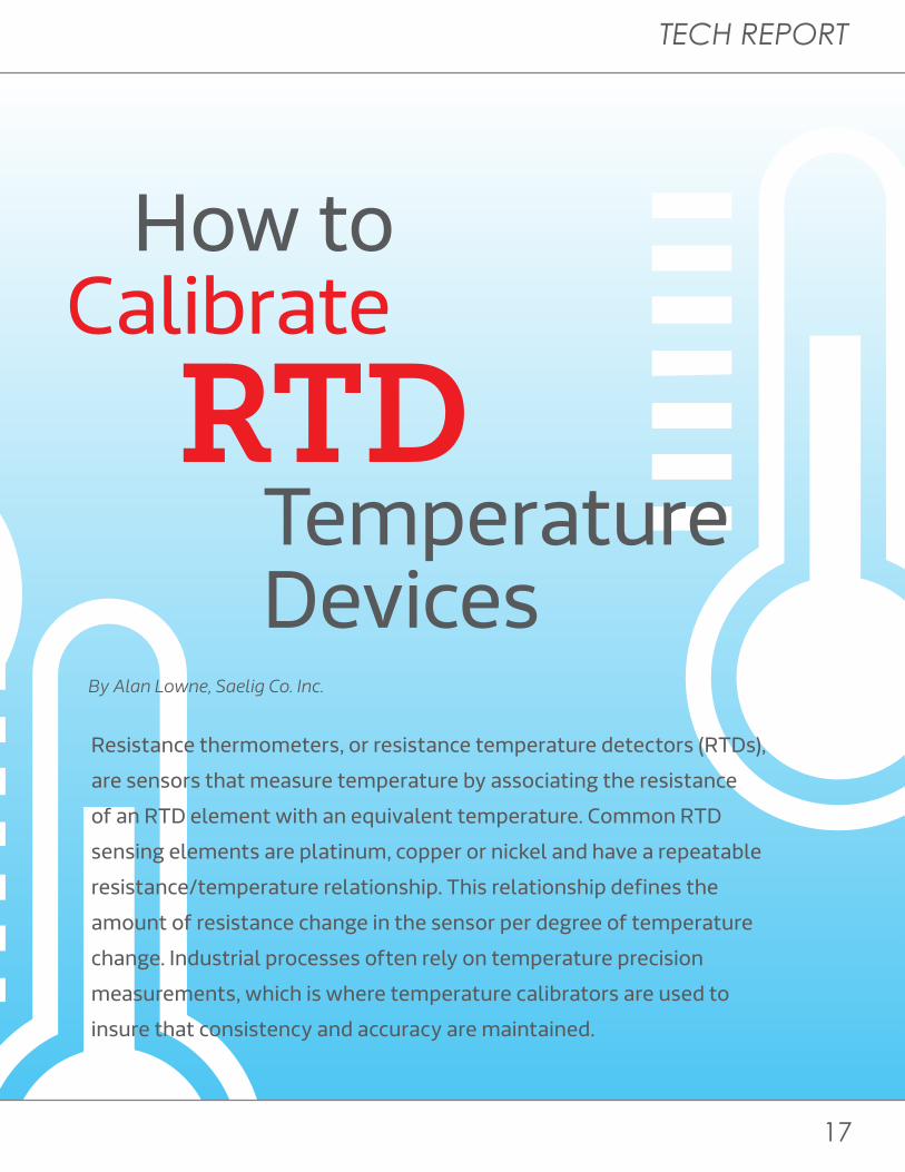
Resistance thermometers, or resistance temperature detectors (RTDs),
are sensors that measure temperature by associating the resistance
of an RTD element with an equivalent temperature. Common RTD
sensing elements are platinum, copper or nickel and have a repeatable
resistance/temperature relationship. This relationship defines the
amount of resistance change in the sensor per degree of temperature
change. Industrial processes often rely on temperature precision
measurements, which is where temperature calibrators are used to
insure that consistency and accuracy are maintained.
TECH REPORT
17
By Alan Lowne, Saelig Co. Inc.
RTD Temperature Devices
How to Calibrate
Resistance thermometers, or resistance temperature detectors (RTDs),
are sensors that measure temperature by associating the resistance
of an RTD element with an equivalent temperature. Common RTD
sensing elements are platinum, copper or nickel and have a repeatable
resistance/temperature relationship. This relationship defines the
amount of resistance change in the sensor per degree of temperature
change. Industrial processes often rely on temperature precision
measurements, which is where temperature calibrators are used to
insure that consistency and accuracy are maintained.

18
Modern Test & Measure
Most RTD sensors consist of a length of fine-coiled sensing wire wrapped around a ceramic
or glass core, and placed inside a sheathed probe to protect it. The wire material has a predictable change in resistance as the temperature changes and that resistance is used to indicate temperature. To detect this resistance change, a current is passed through the sensing material, which has a stable and defined change in resistance versus a change in absolute temperature. The most common example of this is the Platinum PT100 curve equal to 0.00385Ω/Ω/°C. This PT100 curve has a base resistance of 100Ω at 0°C and is typically described according to the Callendar-Van Dusen equation with the associated coefficients. At 100°C the resistance is equal to 138.50Ω (ITS-68) or 138.51Ω (ITS-90). The name of the curve is typically the ratio of resistance at 100°C divided by the resistance at 0°C.
RTDs are typically used for demanding and accurate industrial measurements as well as many general purpose laboratory measurements. While there are many methods of measuring temperature, the RTD remains the most practical for
the high accuracy, mid-range process temperatures ranging from about -100°C to 800°C. Thermocouples and other devices become appropriate for any measurements outside these ranges.
The basic property that makes RTDs so useful is the ease of measuring the inherent change in resistance that is proportional to a change in temperature. The basic principle required to read an RTD is, of course, the simple Ohm’s Law equation: I = V/R, where I is electrical current, V is voltage, and R is resistance. So R = V/I, and, if a known current is driven through an unknown resistance, the resulting voltage can be used to determine the unknown resistance and thus the temperature of the sensor. This is the basic principle for all devices that measure resistance including multi-meters, RTD thermometers, temperature transmitters etc.
While the basic theory of measuring the output of an RTD is relatively simple, there are countless subtle variations in application. These include low measurement currents, high-measurement currents, pulsed and
intermittent currents, switched PLC input currents, split and equal lead currents (typically used for compensating 2, 3 and 4 wire connections), and voltage excitation (not current). Sometimes, all these methods may be combined with polarity switching (for offset voltage cancellation). Some combination of these may be present depending on the particular (or in many cases peculiar) applications for monitoring RTDs.
Unfortunately, the myriad of implementations poses a serious challenge to the users and designers of calibration equipment. Making matters worse, many calibrator designs do not take account of the many techniques used in various types of equipment. Problems with calibrators can result in poor accuracy or repeatability, resulting in replacing transmitters or receivers as the inconsistent troubleshooting brings more problems. There are many calibrators today that cannot be used with all these devices and they rely on technicians knowing when and where to use these calibrators based on the application. This is very challenging since the techniques of how the transmitter accomplishes its specification are rarely disclosed.
Signal Polarity Many calibrators are mistakenly designed for currents flowing in only one direction through the device—they are not bipolar or bidirectional with respect to current. In this case, the calibrator won’t simulate a true resistor. Insidious linearity errors in the calibrator due to internal circuit saturation or leakage currents can also affect the calibrator. This often leads
to the technician to incorrectly assume and blame the transmitters or receivers. Replacing those repeatedly in hopes of fixing the problem can be costly—especially when manufacturing is halted. Even if the calibrator is designed for bidirectional currents, it is important that any internal offset voltages need to be very low. Otherwise this may lead to inconsistent results depending on the polarity of the calibrator from one calibration cycle to the next. This is very important on transmitters or receivers in applications that may use switched polarity readings to cancel thermocouple effects imposed on RTD probes with low-current excitation. This technique is most commonly found only for the most accurate devices and as a result makes it that much more critical that the offsets are accounted for.
Pulsed Currents Pulsed currents are a relatively new feature in field devices and are becoming increasingly popular because they reduce self-heating. PLCs scan several inputs and may only look at the RTD for brief period before switching to another input. These applications require special attention to assure proper operation and calibration, and often field devices requiring calibration often don’t indicate that they use pulsed or intermittent currents. This probably accounts for misunderstandings, time lost, and field problems—more so than any other issue. A calibrator may often appear to work, but give noisy or inconsistent readings, or even a temperature offset. Because of this confusion, field engineers usually replace the installed
Problems with calibrators can result in poor accuracy or repeatability, resulting in replacing transmitters or receivers as the inconsistent troubleshooting brings more problems.
Figure 1. RTD – Platinum PT100 sensor
RTDs are typically used for demanding and accurate industrial measurements as well as many general purpose laboratory measurements.
TECH REPORT
19
Most RTD sensors consist of a length of fine-coiled sensing wire wrapped around a ceramic
or glass core, and placed inside a sheathed probe to protect it. The wire material has a predictable change in resistance as the temperature changes and that resistance is used to indicate temperature. To detect this resistance change, a current is passed through the sensing material, which has a stable and defined change in resistance versus a change in absolute temperature. The most common example of this is the Platinum PT100 curve equal to 0.00385Ω/Ω/°C. This PT100 curve has a base resistance of 100Ω at 0°C and is typically described according to the Callendar-Van Dusen equation with the associated coefficients. At 100°C the resistance is equal to 138.50Ω (ITS-68) or 138.51Ω (ITS-90). The name of the curve is typically the ratio of resistance at 100°C divided by the resistance at 0°C.
RTDs are typically used for demanding and accurate industrial measurements as well as many general purpose laboratory measurements. While there are many methods of measuring temperature, the RTD remains the most practical for
the high accuracy, mid-range process temperatures ranging from about -100°C to 800°C. Thermocouples and other devices become appropriate for any measurements outside these ranges.
The basic property that makes RTDs so useful is the ease of measuring the inherent change in resistance that is proportional to a change in temperature. The basic principle required to read an RTD is, of course, the simple Ohm’s Law equation: I = V/R, where I is electrical current, V is voltage, and R is resistance. So R = V/I, and, if a known current is driven through an unknown resistance, the resulting voltage can be used to determine the unknown resistance and thus the temperature of the sensor. This is the basic principle for all devices that measure resistance including multi-meters, RTD thermometers, temperature transmitters etc.
While the basic theory of measuring the output of an RTD is relatively simple, there are countless subtle variations in application. These include low measurement currents, high-measurement currents, pulsed and
intermittent currents, switched PLC input currents, split and equal lead currents (typically used for compensating 2, 3 and 4 wire connections), and voltage excitation (not current). Sometimes, all these methods may be combined with polarity switching (for offset voltage cancellation). Some combination of these may be present depending on the particular (or in many cases peculiar) applications for monitoring RTDs.
Unfortunately, the myriad of implementations poses a serious challenge to the users and designers of calibration equipment. Making matters worse, many calibrator designs do not take account of the many techniques used in various types of equipment. Problems with calibrators can result in poor accuracy or repeatability, resulting in replacing transmitters or receivers as the inconsistent troubleshooting brings more problems. There are many calibrators today that cannot be used with all these devices and they rely on technicians knowing when and where to use these calibrators based on the application. This is very challenging since the techniques of how the transmitter accomplishes its specification are rarely disclosed.
Signal Polarity Many calibrators are mistakenly designed for currents flowing in only one direction through the device—they are not bipolar or bidirectional with respect to current. In this case, the calibrator won’t simulate a true resistor. Insidious linearity errors in the calibrator due to internal circuit saturation or leakage currents can also affect the calibrator. This often leads
to the technician to incorrectly assume and blame the transmitters or receivers. Replacing those repeatedly in hopes of fixing the problem can be costly—especially when manufacturing is halted. Even if the calibrator is designed for bidirectional currents, it is important that any internal offset voltages need to be very low. Otherwise this may lead to inconsistent results depending on the polarity of the calibrator from one calibration cycle to the next. This is very important on transmitters or receivers in applications that may use switched polarity readings to cancel thermocouple effects imposed on RTD probes with low-current excitation. This technique is most commonly found only for the most accurate devices and as a result makes it that much more critical that the offsets are accounted for.
Pulsed Currents Pulsed currents are a relatively new feature in field devices and are becoming increasingly popular because they reduce self-heating. PLCs scan several inputs and may only look at the RTD for brief period before switching to another input. These applications require special attention to assure proper operation and calibration, and often field devices requiring calibration often don’t indicate that they use pulsed or intermittent currents. This probably accounts for misunderstandings, time lost, and field problems—more so than any other issue. A calibrator may often appear to work, but give noisy or inconsistent readings, or even a temperature offset. Because of this confusion, field engineers usually replace the installed
Problems with calibrators can result in poor accuracy or repeatability, resulting in replacing transmitters or receivers as the inconsistent troubleshooting brings more problems.
Figure 1. RTD – Platinum PT100 sensor
RTDs are typically used for demanding and accurate industrial measurements as well as many general purpose laboratory measurements.

20
Modern Test & Measure
transmitters, controllers or receivers—only to find that the problem persists. Many RTD Calibrators don’t specify operation with pulsed currents. Some calibrator manufacturers do specify compatibility with pulsed or intermittent currents but state a fixed duty cycle such as 10ms/second, which can be very misleading. The technician needs to check that the calibrator responds to repetitive pulses less than 10mS to the full rated accuracy of the device.
Current Ranges Another area often overlooked that leads to many field problems relates to the current ranges allowed. Many of the available RTD calibrators specify very narrow bands of excitation current from the transmitter or receiving device. Many RTD calibrators on the market will specify current ranges as narrow as 0.5mA to 3mA. This is insufficient for
compatibility with many of the newer devices. Many of the latest devices use currents of 0.1mA and lower. Devices that measure lower temperatures or other low resistance curves like Cu10 use 10mA or higher currents. To cope with this, RTD calibrators from PIEcal function from low micro-amps to 20.00mA.
Many calibrators are equipped with just two double insulated banana jacks for simulating RTDs with two-, three-, or four-wire connections (see Fig. 2). These are convenient for two-wire connections but for the more accurate three- and four-wire connections this may introduce significant errors. The contacts or plugs will have to be stacked to achieve three- and four-wire connections, introducing unbalanced paths, and if there is any corrosion or contamination, this can also introduce resistive mismatch errors as well as thermocouple errors. The
thermocouple error for copper corrosion is quite high. Depending on the amount of excitation current, this compromises the total accuracy of the calibrator itself if it not accounted for. A better suggestion is to find a calibrator with four rather than two banana connections for simulating RTDs. Four protected banana sockets reduces the possibility of mismatched corrosion, signal path length errors, and thermocouple effects for high accuracy measurements at lower currents.
RTD Decade Boxes as an Alternative?While a decade box may seem like a convenient compromise in the absence of a high-quality calibrator, there are many accompanying considerations. First, they are scaled in ohms and may lack sufficient accuracy and “set-ability.” Without all the necessary tables, they are useless since the conversion to temperature still needs to be done. This conversion from resistance to temperature is prone to error, especially in the fast-paced process environment. Another insidious error with a decade box is subtle damage due to resistor heating and overload. The same decade box that is used for precision RTD calibration may at times be used in a 4-20mA loop as a current limiter, voltage divider, or some other unintended use. This use can inadvertently cause damage to the precision resistors within a decade box, causing internal resistance values to shift. This may not be discovered until the decade box is recertified (note that a decade box typically cannot be recalibrated). Once one of the internal resistors is damaged, the box may never conform to original specifications.
Most often an offset at different error values will accompany the certification. These error values are intended as a correction that needs to be remembered during calibrations. This will further complicate the calibration process since these will need to be remembered and added or subtracted correctly during the conversion to temperature.
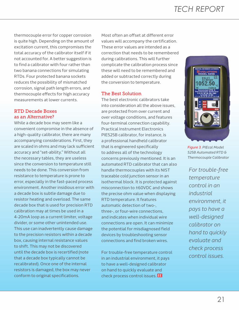
The Best SolutionThe best electronic calibrators take into consideration all the above issues, are protected from over current and over voltage conditions, and features four-terminal connection capability. Practical Instrument Electronics PIE525B calibrator, for instance, is a professional handheld calibrator that is engineered specifically to address all of the technology concerns previously mentioned. It is an automated RTD calibrator that can also handle thermocouples with its NIST traceable cold junction sensor in an isothermal block. It is protected against misconnection to ±60VDC and shows the precise ohm value when displaying RTD temperature. It features automatic detection of two-, three-, or four-wire connections, and indicates when individual wire connections are open. It can minimize the potential for misdiagnosed field devices by troubleshooting sensor connections and find broken wires.
For trouble-free temperature control in an industrial environment, it pays to have a well-designed calibrator on hand to quickly evaluate and check process control issues.
Figure 3. PIEcal Model 525B Automated RTD & Thermocouple Calibrator
EX+ Red
CH+ Red
CH– BlackRTD
EX– Black
IEX
a. Four-Wire RTD Configuration = Connection to Terminal Block
+–
Figure 2. Four-Wire RTD Configuration
For trouble-free temperature control in an industrial environment, it pays to have a well-designed calibrator on hand to quickly evaluate and check process control issues.
Many calibrators are equipped with just two double insulated banana jacks for simulating RTDs with two-, three-, or four-wire connections.
TECH REPORT
21
transmitters, controllers or receivers—only to find that the problem persists. Many RTD Calibrators don’t specify operation with pulsed currents. Some calibrator manufacturers do specify compatibility with pulsed or intermittent currents but state a fixed duty cycle such as 10ms/second, which can be very misleading. The technician needs to check that the calibrator responds to repetitive pulses less than 10mS to the full rated accuracy of the device.
Current Ranges Another area often overlooked that leads to many field problems relates to the current ranges allowed. Many of the available RTD calibrators specify very narrow bands of excitation current from the transmitter or receiving device. Many RTD calibrators on the market will specify current ranges as narrow as 0.5mA to 3mA. This is insufficient for
compatibility with many of the newer devices. Many of the latest devices use currents of 0.1mA and lower. Devices that measure lower temperatures or other low resistance curves like Cu10 use 10mA or higher currents. To cope with this, RTD calibrators from PIEcal function from low micro-amps to 20.00mA.
Many calibrators are equipped with just two double insulated banana jacks for simulating RTDs with two-, three-, or four-wire connections (see Fig. 2). These are convenient for two-wire connections but for the more accurate three- and four-wire connections this may introduce significant errors. The contacts or plugs will have to be stacked to achieve three- and four-wire connections, introducing unbalanced paths, and if there is any corrosion or contamination, this can also introduce resistive mismatch errors as well as thermocouple errors. The
thermocouple error for copper corrosion is quite high. Depending on the amount of excitation current, this compromises the total accuracy of the calibrator itself if it not accounted for. A better suggestion is to find a calibrator with four rather than two banana connections for simulating RTDs. Four protected banana sockets reduces the possibility of mismatched corrosion, signal path length errors, and thermocouple effects for high accuracy measurements at lower currents.
RTD Decade Boxes as an Alternative?While a decade box may seem like a convenient compromise in the absence of a high-quality calibrator, there are many accompanying considerations. First, they are scaled in ohms and may lack sufficient accuracy and “set-ability.” Without all the necessary tables, they are useless since the conversion to temperature still needs to be done. This conversion from resistance to temperature is prone to error, especially in the fast-paced process environment. Another insidious error with a decade box is subtle damage due to resistor heating and overload. The same decade box that is used for precision RTD calibration may at times be used in a 4-20mA loop as a current limiter, voltage divider, or some other unintended use. This use can inadvertently cause damage to the precision resistors within a decade box, causing internal resistance values to shift. This may not be discovered until the decade box is recertified (note that a decade box typically cannot be recalibrated). Once one of the internal resistors is damaged, the box may never conform to original specifications.
Most often an offset at different error values will accompany the certification. These error values are intended as a correction that needs to be remembered during calibrations. This will further complicate the calibration process since these will need to be remembered and added or subtracted correctly during the conversion to temperature.
The Best SolutionThe best electronic calibrators take into consideration all the above issues, are protected from over current and over voltage conditions, and features four-terminal connection capability. Practical Instrument Electronics PIE525B calibrator, for instance, is a professional handheld calibrator that is engineered specifically to address all of the technology concerns previously mentioned. It is an automated RTD calibrator that can also handle thermocouples with its NIST traceable cold junction sensor in an isothermal block. It is protected against misconnection to ±60VDC and shows the precise ohm value when displaying RTD temperature. It features automatic detection of two-, three-, or four-wire connections, and indicates when individual wire connections are open. It can minimize the potential for misdiagnosed field devices by troubleshooting sensor connections and find broken wires.
For trouble-free temperature control in an industrial environment, it pays to have a well-designed calibrator on hand to quickly evaluate and check process control issues.
Figure 3. PIEcal Model 525B Automated RTD & Thermocouple Calibrator
EX+ Red
CH+ Red
CH– BlackRTD
EX– Black
IEX
a. Four-Wire RTD Configuration = Connection to Terminal Block
+–
Figure 2. Four-Wire RTD Configuration
For trouble-free temperature control in an industrial environment, it pays to have a well-designed calibrator on hand to quickly evaluate and check process control issues.
Many calibrators are equipped with just two double insulated banana jacks for simulating RTDs with two-, three-, or four-wire connections.

Schematics.com
Your Circuit Starts Here.Sign up to design, share, and collaborate
on your next project—big or small.
Click Here to Sign Up
Upload Quote Order
Simple. Custom. Quality.

ORDER
Click Here
Find potential problems more quickly with the higher resolution and affordability of the U5850 series TrueIR thermal imagers. Get 320 x 240 pixels of in-camera fine resolution from its detector resolution of 160 x 120 pixels. With the built-in image logging capability, easily track performance of the system you monitor at a specific interval. Plus, you can analyze temperature changes over time with trending graph.
Coupled with the powerful manual focus feature, users can focus on an object as close as 10 cm away - our solution provides clearer and sharper thermal images that reveal finer details.
Keysight TrueIR Thermal Imagersfrom Gap Wireless
Upload Quote Order
Simple. Custom. Quality.

24
Modern Test & Measure
POWER Arena
Keysight Targets
Interview with Kari Fauber – GM of the Power & Energy Division at Keysight Technologies
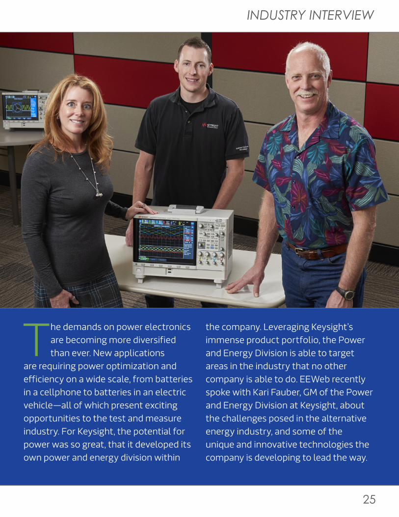
The demands on power electronics are becoming more diversified than ever. New applications
are requiring power optimization and efficiency on a wide scale, from batteries in a cellphone to batteries in an electric vehicle—all of which present exciting opportunities to the test and measure industry. For Keysight, the potential for power was so great, that it developed its own power and energy division within
the company. Leveraging Keysight’s immense product portfolio, the Power and Energy Division is able to target areas in the industry that no other company is able to do. EEWeb recently spoke with Kari Fauber, GM of the Power and Energy Division at Keysight, about the challenges posed in the alternative energy industry, and some of the unique and innovative technologies the company is developing to lead the way.
Test Technology Optimizes Efficiency in Alternative Energy Applications
INDUSTRY INTERVIEW
25
POWER Arena
Keysight Targets
Interview with Kari Fauber – GM of the Power & Energy Division at Keysight Technologies
The demands on power electronics are becoming more diversified than ever. New applications
are requiring power optimization and efficiency on a wide scale, from batteries in a cellphone to batteries in an electric vehicle—all of which present exciting opportunities to the test and measure industry. For Keysight, the potential for power was so great, that it developed its own power and energy division within
the company. Leveraging Keysight’s immense product portfolio, the Power and Energy Division is able to target areas in the industry that no other company is able to do. EEWeb recently spoke with Kari Fauber, GM of the Power and Energy Division at Keysight, about the challenges posed in the alternative energy industry, and some of the unique and innovative technologies the company is developing to lead the way.
Test Technology Optimizes Efficiency in Alternative Energy Applications

26
Modern Test & Measure
What is Keysight doing in the power and energy arena?
Two years ago, we recognized that there were a lot of trends in the power and energy markets that were driving significant change, which created a lot of opportunities from a test and measurement perspective. As a result, we created the power and energy division and we took the power products that had existed within HP-Agilent and consolidated them into this organization. When we started this division, we thought about our main area of focus—when you talk about power and energy, that encompasses a huge market and with a lot of diverse technologies.
Within this division, our team had identified a few opportunities, specifically those that drive emerging trends in the marketplace. In consumer devices, battery management and power optimization is really critical for device acceptance by consumers. The technologies used for batteries are low power in consumer devices and are very similar to batteries used in larger, higher-power devices like electric vehicles. Power optimization and battery efficiency is becoming a requirement in these application areas, from mobile devices to electric vehicles. We specifically focused on three application areas: power conversion, power optimization within a device, and power storage; we have found that within the market, those specific application areas are growing tremendously. Last year alone, the power market grew 12%, and that
combines both the generic power market as well as the specific power applications, which are growing even faster.
What are the differences in dealing with power optimization to electric vehicles?
With a mobile device like a cellphone or tablet, designers typically look at how to optimize the power usage—in most cases, it is typically the current that needs to be addressed to power certain functions. As a consumer, nobody wants to have to recharge his or her phone more than once a day. They are mostly willing to do it at night, but they are unlikely to do it midday after they watch a video or download photos. The current is typically 3 amps on a phone or 10 amps on a tablet, whereas for an electric vehicle, it is orders of magnitude higher. The precision, therefore, is less. If you have a sleep current in a mobile phone, it is typically in the nanoamp range. Sleep current in a car is still in the amps range, so it is significantly higher levels of power. However, the concepts behind the two are essentially the same. The user is still worried about how quickly they are draining the battery or how efficient their power usage is as they are doing different things.
On the power side, what kind of unique technologies or innovations has Keysight been able to develop to get the upper hand?
I will give you two examples of innovation. One would be measuring the power or current usage in either a cellphone or in an electric vehicle.
Keysight has the most precise measurement capabilities for power, both for the voltage and current capability across the company because we have DMMs in our portfolio, as well as semiconductor characterization parametric test products that can measure really low currents and really high voltages. We are able to leverage that measurement technology into our power supplies that do a battery drain characterization for cellphones. We are then able to take that type of measurement technology, although not at the same level, and use that to do very fast transient response for our power supplies and power measurement systems that go into test solutions for automotive applications.
The second example is with our new power analyzer, which is a product category that we entered around a year ago. We have the unique ability
“Last year alone, the power market grew 12%, and that combines both the generic power market as well as the specific power applications, which are growing even faster.”
“We specifically focused on three application areas: power conversion, power optimization within a device, and power storage...”

INDUSTRY INTERVIEW
27
What is Keysight doing in the power and energy arena?
Two years ago, we recognized that there were a lot of trends in the power and energy markets that were driving significant change, which created a lot of opportunities from a test and measurement perspective. As a result, we created the power and energy division and we took the power products that had existed within HP-Agilent and consolidated them into this organization. When we started this division, we thought about our main area of focus—when you talk about power and energy, that encompasses a huge market and with a lot of diverse technologies.
Within this division, our team had identified a few opportunities, specifically those that drive emerging trends in the marketplace. In consumer devices, battery management and power optimization is really critical for device acceptance by consumers. The technologies used for batteries are low power in consumer devices and are very similar to batteries used in larger, higher-power devices like electric vehicles. Power optimization and battery efficiency is becoming a requirement in these application areas, from mobile devices to electric vehicles. We specifically focused on three application areas: power conversion, power optimization within a device, and power storage; we have found that within the market, those specific application areas are growing tremendously. Last year alone, the power market grew 12%, and that
combines both the generic power market as well as the specific power applications, which are growing even faster.
What are the differences in dealing with power optimization to electric vehicles?
With a mobile device like a cellphone or tablet, designers typically look at how to optimize the power usage—in most cases, it is typically the current that needs to be addressed to power certain functions. As a consumer, nobody wants to have to recharge his or her phone more than once a day. They are mostly willing to do it at night, but they are unlikely to do it midday after they watch a video or download photos. The current is typically 3 amps on a phone or 10 amps on a tablet, whereas for an electric vehicle, it is orders of magnitude higher. The precision, therefore, is less. If you have a sleep current in a mobile phone, it is typically in the nanoamp range. Sleep current in a car is still in the amps range, so it is significantly higher levels of power. However, the concepts behind the two are essentially the same. The user is still worried about how quickly they are draining the battery or how efficient their power usage is as they are doing different things.
On the power side, what kind of unique technologies or innovations has Keysight been able to develop to get the upper hand?
I will give you two examples of innovation. One would be measuring the power or current usage in either a cellphone or in an electric vehicle.
Keysight has the most precise measurement capabilities for power, both for the voltage and current capability across the company because we have DMMs in our portfolio, as well as semiconductor characterization parametric test products that can measure really low currents and really high voltages. We are able to leverage that measurement technology into our power supplies that do a battery drain characterization for cellphones. We are then able to take that type of measurement technology, although not at the same level, and use that to do very fast transient response for our power supplies and power measurement systems that go into test solutions for automotive applications.
The second example is with our new power analyzer, which is a product category that we entered around a year ago. We have the unique ability
“Last year alone, the power market grew 12%, and that combines both the generic power market as well as the specific power applications, which are growing even faster.”
“We specifically focused on three application areas: power conversion, power optimization within a device, and power storage...”

28
Modern Test & Measure
within test and measurement as well to leverage user interface technology—in this case, we took the technology from the 6000-series oscilloscope product division. We had invested over 37 years in user interface technology, and in the last 5 years we have invested a lot in touch screen capability. We took their user interface and combined that with the measurement technology around isolated channel voltages to come up with a power analyzer that is unmatched in the industry in terms of ease of use. A company like Keysight has such a broad portfolio, so we like to take advantage of the technologies across the company to be able to do things that nobody else can do.
What kind of trends are you seeing in the efficiency aspect of the power industry?
Efficiency is probably one of the major driving forces across the power industry—the drive towards more sustainable energy, which drives the trend toward electric vehicle adoption. In a recent report, Europe and Japan are expected to see the adoption rate of electric vehicles to go from 15% today to 60% in 2020. This is due in part by government subsidies and influences to drive the adoption higher so drivers do not pay as much on the vehicle taxes.
Another major trend is around safety, which is driving a lot of testing into the battery space. As you can imagine, if you have a battery for a home energy management system or for an electric vehicle, you have to be confident that your battery is safe and that it will not cause any potential damage to the humans or to your home. Safety has driven up the test requirements as well.
The third mega trend is the consolidation and continued proliferation of electronics in everything. There are way more things that your phone can do today than it could five years ago, which is also the case with your car. All of that pulls on the source of power, which is the battery. Those mega trends have really driven the increase in the market need for power systems, power solutions, and equipment to measure power efficiency.
Everything is increasingly becoming more dependent on power now and every day, devices are getting smarter. However, power is not getting as much attention. In the world of power, what is it that gets Keysight excited?
Power is the fundamental enabler for any of the advancements today. If it
is with 5G, we need to find out how to power 5G coverage around the globe, leveraging the existing infrastructure as much as possible, and expanding where it is needed. 5G is going to pull more power than 4G or 3G did, so we need to figure out how to do that effectively and efficiently without relying as much on fossil fuels. We are really a part of something that is at the heart of everything these days. While we use the human analogy of the “heart” of the system, there also needs to be the “brain” and thought, which comes from the spectrum analyzer. However, without the heart, nothing else works, no matter how good the other elements of the system are.
“A company like Keysight has such a broad portfolio, so we like to take advantage of the technologies across the company to be able to do things that nobody else can do.”
What upcoming challenges do you anticipate in this area?
Batteries are getting bigger, more powerful, higher current, and higher voltage, whether we are talking about the sourcing side or the battery side. This is something that has not been explored well from a test and measurement perspective. There are brute force technologies for utilities, but a high level of precision is needed to ensure you have an inverter or battery that is optimized and safe. That is a key change happening in the industry.

INDUSTRY INTERVIEW
29
within test and measurement as well to leverage user interface technology—in this case, we took the technology from the 6000-series oscilloscope product division. We had invested over 37 years in user interface technology, and in the last 5 years we have invested a lot in touch screen capability. We took their user interface and combined that with the measurement technology around isolated channel voltages to come up with a power analyzer that is unmatched in the industry in terms of ease of use. A company like Keysight has such a broad portfolio, so we like to take advantage of the technologies across the company to be able to do things that nobody else can do.
What kind of trends are you seeing in the efficiency aspect of the power industry?
Efficiency is probably one of the major driving forces across the power industry—the drive towards more sustainable energy, which drives the trend toward electric vehicle adoption. In a recent report, Europe and Japan are expected to see the adoption rate of electric vehicles to go from 15% today to 60% in 2020. This is due in part by government subsidies and influences to drive the adoption higher so drivers do not pay as much on the vehicle taxes.
Another major trend is around safety, which is driving a lot of testing into the battery space. As you can imagine, if you have a battery for a home energy management system or for an electric vehicle, you have to be confident that your battery is safe and that it will not cause any potential damage to the humans or to your home. Safety has driven up the test requirements as well.
The third mega trend is the consolidation and continued proliferation of electronics in everything. There are way more things that your phone can do today than it could five years ago, which is also the case with your car. All of that pulls on the source of power, which is the battery. Those mega trends have really driven the increase in the market need for power systems, power solutions, and equipment to measure power efficiency.
Everything is increasingly becoming more dependent on power now and every day, devices are getting smarter. However, power is not getting as much attention. In the world of power, what is it that gets Keysight excited?
Power is the fundamental enabler for any of the advancements today. If it
is with 5G, we need to find out how to power 5G coverage around the globe, leveraging the existing infrastructure as much as possible, and expanding where it is needed. 5G is going to pull more power than 4G or 3G did, so we need to figure out how to do that effectively and efficiently without relying as much on fossil fuels. We are really a part of something that is at the heart of everything these days. While we use the human analogy of the “heart” of the system, there also needs to be the “brain” and thought, which comes from the spectrum analyzer. However, without the heart, nothing else works, no matter how good the other elements of the system are.
“A company like Keysight has such a broad portfolio, so we like to take advantage of the technologies across the company to be able to do things that nobody else can do.”
What upcoming challenges do you anticipate in this area?
Batteries are getting bigger, more powerful, higher current, and higher voltage, whether we are talking about the sourcing side or the battery side. This is something that has not been explored well from a test and measurement perspective. There are brute force technologies for utilities, but a high level of precision is needed to ensure you have an inverter or battery that is optimized and safe. That is a key change happening in the industry.

Click here
Sierra Circuits:A Complete PCB Resource
PLUS: The Ground ” Myth in PrintedCircuits
“
PCB Resin Reactor+
Ken BahlCEO of Sierra Circuits
Let There Be
How Cree reinvented the light bulb
LIGHT
David ElienVP of Marketing & Business
Development, Cree, Inc.
New LED Filament Tower
Cutting Edge Flatscreen Technologies
+
+
M o v i n g T o w a r d s
a Clean Energy
FUTURE— Hugo van Nispen, COO of DNV KEMA
MCU Wars 32-bit MCU Comparison
Cutting Edge
SPICEModeling
Freescale and TI Embedded
Modules
ARMCortex
Programming
From Concept to
Reality Wolfgang Heinz-Fischer
Head of Marketing & PR, TQ-Group
Low-Power Design Techniques
TQ-Group’s Comprehensive Design Process
+
+
PowerDeveloper
Octobe r 20 13
Designing forDurability
View more EEWeb magazines— Click Here