Modern technologies of fabrication and testing of large...
13
Modern technologies of fabrication and testing of large convex secondary mirrors Item Type Article Authors Oh, Chang Jin; Lowman, Andrew E.; Dubin, Matt; Smith, Greg; Frater, Eric; Zhao, Chunyu; Burge, James H. Citation Chang Jin Oh ; Andrew E. Lowman ; Matt Dubin ; Greg Smith ; Eric Frater ; Chunyu Zhao and James H. Burge " Modern technologies of fabrication and testing of large convex secondary mirrors ", Proc. SPIE 9912, Advances in Optical and Mechanical Technologies for Telescopes and Instrumentation II, 99120R (July 22, 2016); doi:10.1117/12.2233887; http:// dx.doi.org/10.1117/12.2233887 DOI 10.1117/12.2233887 Publisher SPIE-INT SOC OPTICAL ENGINEERING Journal ADVANCES IN OPTICAL AND MECHANICAL TECHNOLOGIES FOR TELESCOPES AND INSTRUMENTATION II Rights © 2016 SPIE Download date 28/07/2018 04:37:09 Link to Item http://hdl.handle.net/10150/622427
-
Upload
trinhhuong -
Category
Documents
-
view
218 -
download
0
Transcript of Modern technologies of fabrication and testing of large...
Modern technologies of fabrication andtesting of large convex secondary mirrors
Item Type Article
Authors Oh, Chang Jin; Lowman, Andrew E.; Dubin, Matt; Smith, Greg;Frater, Eric; Zhao, Chunyu; Burge, James H.
Citation Chang Jin Oh ; Andrew E. Lowman ; Matt Dubin ; Greg Smith ;Eric Frater ; Chunyu Zhao and James H. Burge " Moderntechnologies of fabrication and testing of large convexsecondary mirrors ", Proc. SPIE 9912, Advances in Optical andMechanical Technologies for Telescopes and InstrumentationII, 99120R (July 22, 2016); doi:10.1117/12.2233887; http://dx.doi.org/10.1117/12.2233887
DOI 10.1117/12.2233887
Publisher SPIE-INT SOC OPTICAL ENGINEERING
Journal ADVANCES IN OPTICAL AND MECHANICAL TECHNOLOGIES FORTELESCOPES AND INSTRUMENTATION II
Rights © 2016 SPIE
Download date 28/07/2018 04:37:09
Link to Item http://hdl.handle.net/10150/622427

Modern Technologies of Fabrication and Testing of Large Convex Secondary Mirrors
Chang Jin Oh *a, Andrew E. Lowman a, Matt Dubin a, Greg Smith a, Eric Frater a, Chunyu Zhao a,
James H. Burge a
a College of Optical Sciences, the University of Arizona 1630 E. University Blvd, Tucson, AZ, 85721, USA
ABSTRACT
Modern large telescopes such as TAO, LSST, TMT and EELT require 0.9m-4m monolithic convex secondary mirrors. The fabrication and testing of these large convex secondary mirrors of astronomical telescopes is getting challenging as the aperture of the mirror is getting bigger. The biggest challenge to fabricate these large convex aspheric mirrors is to measure the surface figure to a few nanometers, while maintaining the testing and fabrication cycle to be efficient to minimize the downtime. For the last a couple of decades there was huge advancement in the metrology and fabrication of large aspheric secondary mirrors. College of Optical Sciences in the University Arizona developed a full fabrication and metrology process with extremely high accuracy and efficiency for manufacturing the large convex secondary mirrors.
In this paper modern metrology systems including Swing-Arm Optical Coordinate Measuring System (SOCMM) which is comparable to Interferometry and a Sub-aperture stitching interferometry scalable to a several meters have been presented. Also a Computer Controlled Fabrication Process which produces extremely fine surface figure and finish has been demonstrated. These most recent development has been applied to the fabrication and testing of 0.9m aspheric convex secondary mirror for the Tokyo Atacama Observatory’s 6.5m telescope and the result has been presented. Keywords: Convex, Secondary Mirror, Aspheric, Swingarm Optical CMM, Stitching Interferometry, Fabrication
1. INTRODUCTION Aspheric surfaces are used in optical systems in order to improve aberration correction and, frequently, to decrease
the number of optical elements needed to make this correction satisfactorily. However, if these surfaces are tested while being isolated from the rest of the optical system to which they belong, they frequently produce aspherical wavefronts. The interferometric testing and measurement of aspherical wavefronts are not as simple as in the case of spherical or flat wavefronts. 1 To test aspherics, often an interferometric null test is applied with an additional optical components such as corrector, CGH, etc.
Testing of a convex secondary mirror of astronomical telescope has been considered to be difficult mostly due to the nature of the convex and aspheric geometry. Tests of optical surfaces all rely in some form or other on the formation of the image of a point source by an optical arrangement containing the test surface. The errors of the test surface are impressed on the incident wavefront and are deterrnined by analysis of the image. Since the object source is by definition real and only a real image is accessible for analysis, it follows that the optical arrangement must be capable of yielding a real image of a real object. A convex reflecting surface is incapable of doing this without auxiliary optics. This characteristic, combined with its high eccentricity, makes the manufacture of the secondary one of the major problems. 2 There have been a few conventional methods used for the testing of aspheric convex secondary mirrors.
In the following sections a few conventional methodologies of testing of convex secondary mirrors are discussed as well as modern technologies including SOCMM and stitching interferometry. *[email protected]
Advances in Optical and Mechanical Technologies for Telescopes and Instrumentation II, edited by Ramón Navarro, James H. Burge, Proc. of SPIE Vol. 9912, 99120R
© 2016 SPIE · CCC code: 0277-786X/16/$18 · doi: 10.1117/12.2233887
Proc. of SPIE Vol. 9912 99120R-1
Downloaded From: http://proceedings.spiedigitallibrary.org/ on 01/30/2017 Terms of Use: http://spiedigitallibrary.org/ss/termsofuse.aspx

11M11744111J
%ivr= 1g, Co.wiGp`r2:,kropwr?tiO .` óiiii ; ;Zitie
E 210-04
----
_-- -----
2. CONVENTIONAL METHODOLOGIESIn this section we will discuss a few conventional methodologies of testing a convex secondary mirror including Conjugate/Collimation test, Hindle test and Meinel test. The full aperture interferometry using a CGH test plate and Profilometer techniques are also reviewed.
2.1 Conjugate/Collimation Test
Functional test with natural star is the oldest and most direct method. 2 By configuring the designed telescope, a bright natural star image can be obtained through the M1 and M2. This test is affected by the natural seeing significantly and also requires actual (or a serious) telescope mount. Although it is lacking fabrication efficiency, this test was performed in the past.
The conjugate test or Autocollimation test is a more practical method which can be performed in a conventional optical shop facility. A typical configuration and example are shown in Figure 1. Using a reference flat which is large enough to cover the aperture of the telescope, the conjugate point can be used for the test. By knowing the condition of the primary mirror and the flat used the secondary mirror figure can be measured. This test is configured in double path which allow higher sensitivity but requires large flat and a finished primary mirror.
Figure 1. Configuration of conjugate/Autocollimation test (Up) and actual test configuration (Down)
2.2 Hindle Test
The most common test for the convex secondary mirrors has been implemented by using a Hindle sphere as described in Figure 2. As mentioned in the above, when a null test is obtained, then the center of curvature of the illuminating wavefront is at the proper focus; but since at least one of the geometrical foci is inaccessible, additional optical elements are required. A convex hyperboloidal surface can be tested with the method proposed by Hindle in
Proc. of SPIE Vol. 9912 99120R-2
Downloaded From: http://proceedings.spiedigitallibrary.org/ on 01/30/2017 Terms of Use: http://spiedigitallibrary.org/ss/termsofuse.aspx
1r aspherlcr RoC=2424.242rnrn
52. where, RoC=41C10,23man(need to be polished.)
"Zr.__" rm.'
dng 1279.84mmmas, VOW
Interferometer
Light source and
testing point
!Auxiliary spherical rnlrror Convex
hyperboloidal mirror under test
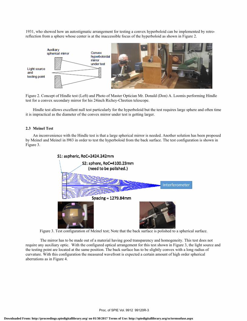
1931, who showed how an autostigmatic arrangement for testing a convex hyperboloid can be implemented by retro-reflection from a sphere whose center is at the inaccessible focus of the hyperboloid as shown in Figure 2.
Figure 2. Concept of Hindle test (Left) and Photo of Master Optician Mr. Donald (Don) A. Loomis performing Hindle test for a convex secondary mirror for his 24inch Richey-Chretien telescope.
Hindle test allows excellent null test particularly for the hyperboloid but the test requires large sphere and often time it is impractical as the diameter of the convex mirror under test is getting larger.
2.3 Meinel Test
An inconvenience with the Hindle test is that a large spherical mirror is needed. Another solution has been proposed by Meinel and Meinel in l983 in order to test the hyperboloid from the back surface. The test configuration is shown in Figure 3.
Figure 3. Test configuration of Meinel test; Note that the back surface is polished to a spherical surface.
The mirror has to be made out of a material having good transparency and homogeneity. This test does not require any auxiliary optic. With the configured optical arrangement for this test shown in Figure 3, the light source and the testing point are located at the same position. The back surface has to be slightly convex with a long radius of curvature. With this configuration the measured wavefront is expected a certain amount of high order spherical aberrations as in Figure 4.
Proc. of SPIE Vol. 9912 99120R-3
Downloaded From: http://proceedings.spiedigitallibrary.org/ on 01/30/2017 Terms of Use: http://spiedigitallibrary.org/ss/termsofuse.aspx

CGH w /alignmentsets tip /tilt and spiinterferometer
S.tn.=
:.Fup:.:
:.1-Sr:.:
:.:ap:.:
:.:ap:.:
T. ï.up::i
i.':ir::i
:.:; :a.
-T.:ap::i
Figure 4. Expected wavefront response from the Meinel test (Left) and measured result from an actual test (Right) from the test configureation in Figure 3.
As pointed out by Meinel, a better solution is obtained if the back surface is made flat and the spherical aberration is completely corrected by locating the light source and the testing point along the optical axis, separated some distance from each other.
2.4 Meinel Test Using a CGH
As explained in above Meinel test leaves a certain amount of residual aberrations and also the test result is affected by the homogeneity and shape of the blank. In order to make a precision measurement of the convex aspheric surface figure a Computer Generated Hologram(CGH) can be used in the test configuration. Figure 5 shows a test set up for the surface figure measurement in Meinel test. The CGH is designed and used to compensate the expected residual aberration.
Figure 5. Configuration of a Meinel test with CGH (Left) and a photo of the actual test; the CGH is designed to compensate the residual aberration down to approximately 2nm RMS or less.
In order to remove the effect from the homogeneity and the shape of the blank, a test set up can be configured as in Figure 6. A calibration CGH is designed to remove the residual aberration from the test and it will allow a null test. For this test a CGH is designed to compensate the residual aberration down to 1nm RMS or less.
Proc. of SPIE Vol. 9912 99120R-4
Downloaded From: http://proceedings.spiedigitallibrary.org/ on 01/30/2017 Terms of Use: http://spiedigitallibrary.org/ss/termsofuse.aspx
- tr.t,
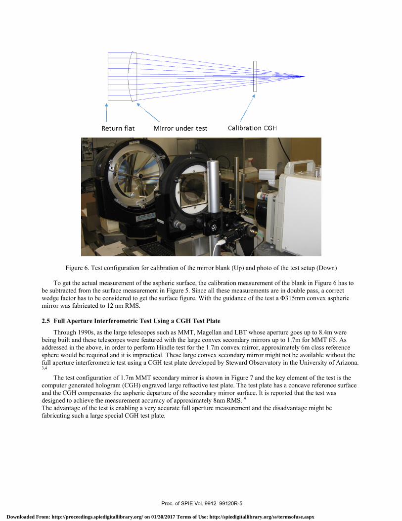
Figure 6. Test configuration for calibration of the mirror blank (Up) and photo of the test setup (Down)
To get the actual measurement of the aspheric surface, the calibration measurement of the blank in Figure 6 has to be subtracted from the surface measurement in Figure 5. Since all these measurements are in double pass, a correct wedge factor has to be considered to get the surface figure. With the guidance of the test a Φ315mm convex aspheric mirror was fabricated to 12 nm RMS.
2.5 Full Aperture Interferometric Test Using a CGH Test Plate
Through 1990s, as the large telescopes such as MMT, Magellan and LBT whose aperture goes up to 8.4m were being built and these telescopes were featured with the large convex secondary mirrors up to 1.7m for MMT f/5. As addressed in the above, in order to perform Hindle test for the 1.7m convex mirror, approximately 6m class reference sphere would be required and it is impractical. These large convex secondary mirror might not be available without the full aperture interferometric test using a CGH test plate developed by Steward Observatory in the University of Arizona. 3,4
The test configuration of 1.7m MMT secondary mirror is shown in Figure 7 and the key element of the test is the computer generated hologram (CGH) engraved large refractive test plate. The test plate has a concave reference surface and the CGH compensates the aspheric departure of the secondary mirror surface. It is reported that the test was designed to achieve the measurement accuracy of approximately 8nm RMS. 4
The advantage of the test is enabling a very accurate full aperture measurement and the disadvantage might be fabricating such a large special CGH test plate.
Proc. of SPIE Vol. 9912 99120R-5
Downloaded From: http://proceedings.spiedigitallibrary.org/ on 01/30/2017 Terms of Use: http://spiedigitallibrary.org/ss/termsofuse.aspx

- -¡_ í=,
rotarystage
probe andarm alignment stages
probe trajectory
optical axis
ofrotation
center of curvature \06
r
O TOP CRM!
SECONDARY AND TEST PLATE SUPPORT
.on kii:..ruëEnTr POLO PLAT,
l
A>s1YTN MARUA
LINEAR ISTASIS
1TMDP[O LAP POYFLIIMITM 'MOOG AA11 PAOPLOLt1IR
In
TOUNR /RALO
Figure 7. Layout of the secondary test system including details of optics support. 4
2.6 Swingarm Profilometer: 1997
Coordinate Measuring Machine (CMM) is a versatile tool for optical surface measurement. It is reported that a precision CMM along with null test was used for fabrication of 1.45m f/15 convex secondary for Keck telescope I and II. The CMM used for Keck telescope secondary mirror is constructed by Anorad and uses Cartesian coordinate systemfeatured a Hewlett-Packard’s distance measuring interferometer to achieve high accuracy. 5
Figure 8. Principle of Swingarm Profilometer for a convex mirror measurement (Left) and the Swingarm profilometer setup for 1.7m MMT f/5 secondary mirror in 1997 (Right)
Proc. of SPIE Vol. 9912 99120R-6
Downloaded From: http://proceedings.spiedigitallibrary.org/ on 01/30/2017 Terms of Use: http://spiedigitallibrary.org/ss/termsofuse.aspx

Swingarm profilometer developed by the University of Arizona is also very useful tool in aspheric optical surface measurement. The principle of Swingarm profilometer is presented in Figure 8.
As in the figure the Swingarm profilometer consists with two main elements. One is the turntable that holds the secondary mirror and the other is the air-bearing mounted Swingarm whose axis of rotation pointing the center of curvature of the mirror under test. With the configuration the trajectory of the tip of the sensor mounted to the end of swingarm follows the best-fit spherical surface of the mirror under test. During the scan the sensor measures the aspheric departure from the virtual reference surface. As reported, in 1997 the Swingarm profilometer used a contact type precision air-bearing guided LVDT and the actual measurement was done in discrete “stop-down-measure-lift-move” style. Due to the limitation of sensor and software only profile measurement was available and the accuracy was achieved to approximately 50nm RMS.6
3. MODERN METHODOLOGIES FOR A LARGE CONVEX MIRROR FOR GIANTTELESCOPES
At present there are three giant telescopes (LSST, TMT and EELT) that requires large convex mirrors are being built. These giant telescopes adopt large convex mirrors between 3.1m-4m. With the conventional technologies it is impractical to measure these multi-meter class convex aspheric mirrors. The University of Arizona developed advanced swingarm profilometer and sub-aperture stitching interferometer that can be scalable to multi-meter class large convex aspheric mirrors.
In this section we will discuss about the latest Swingarm profilometer and sub-aperture stitching interferometer technologies applied to a 1m class convex mirror fabrication and testing.
3.1 Swingarm Optical CMM (SOCMM): 2016
The SOCMM is developed with advanced features in the non-contact interferometric sensor to measure the departure and the algorithm to reconstruct the measured surface by stitching the multiple scanned profiles. With these features the random error in the scanned profiles is less than 3nm RMS and with the calibration of systematic error in the swingarm bearing the measurement error can as good as 10nm RMS. Figure 9 presents 128 scan pattern over 1m class convex aspheric secondary mirror and the actual test set up.
-500 -400 -300 -200 -100 0 100 200 300 400 500
-400
-300
-200
-100
0
100
200
300
400
profiling pattern
A
B
Figure 9. 128 scan pattern over 1m class convex mirror (Left) and actual SOCMM test set up (Right)
SOCMM was mounted the computer controlled polishing system and provided in-situ metrology. The SOCMM was used extensively in guiding the fabrication of the mirror from the grinding phase to the final finish. Figure 10 shows the reduced final surface map of the convex mirror.
Proc. of SPIE Vol. 9912 99120R-7
Downloaded From: http://proceedings.spiedigitallibrary.org/ on 01/30/2017 Terms of Use: http://spiedigitallibrary.org/ss/termsofuse.aspx
Mirror under
test
Number of subapertures contributing to each pixelV
5
4
Statistics within all area (up) & clear aperture (down)PV: 1.3866, Mean: 9.4278e -011, RMS: 0.14216 (pm)PV: 1.3866, Mean: 9.4278e -011, RMS: 0.14216 (pm)
-400 .200 0
MM200 400
0.8
0.6
.4
.2
-0.2
-0.4
-0.6
-0.8
_1
i
400
300
200
100
E 0E
-100
-200
-300
-400
Statistics within all area (up) & clear aperture (down)PV: 0.63185, Mean: 0.0021059, RMS: 0.029433 (pm)PV: 0.63185, Mean: 0.0021059, RMS: 0.029433 (pm)
-400 -200 Ilfri
200 400
.25
.2
015
01
005
0 E.
05
-0.1
-0.15
-0.2
-0.25
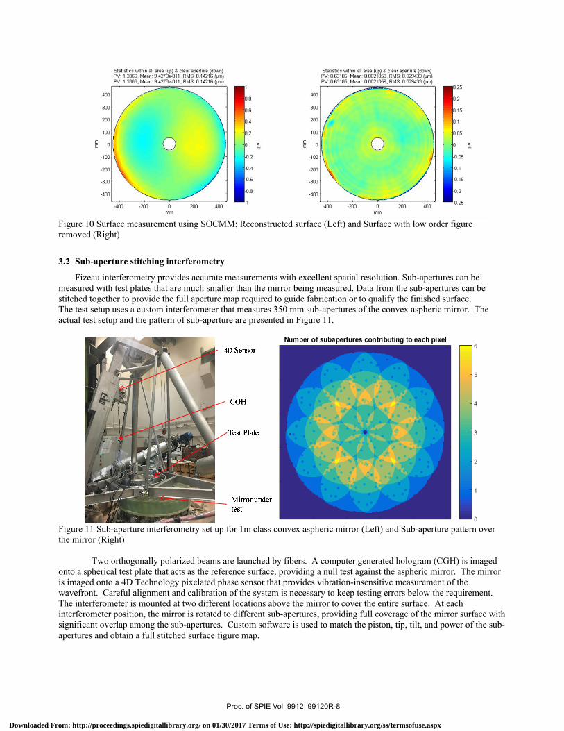
Figure 10 Surface measurement using SOCMM; Reconstructed surface (Left) and Surface with low order figure removed (Right)
3.2 Sub-aperture stitching interferometry
Fizeau interferometry provides accurate measurements with excellent spatial resolution. Sub-apertures can be measured with test plates that are much smaller than the mirror being measured. Data from the sub-apertures can be stitched together to provide the full aperture map required to guide fabrication or to qualify the finished surface. The test setup uses a custom interferometer that measures 350 mm sub-apertures of the convex aspheric mirror. The actual test setup and the pattern of sub-aperture are presented in Figure 11.
Figure 11 Sub-aperture interferometry set up for 1m class convex aspheric mirror (Left) and Sub-aperture pattern over the mirror (Right)
Two orthogonally polarized beams are launched by fibers. A computer generated hologram (CGH) is imaged onto a spherical test plate that acts as the reference surface, providing a null test against the aspheric mirror. The mirror is imaged onto a 4D Technology pixelated phase sensor that provides vibration-insensitive measurement of the wavefront. Careful alignment and calibration of the system is necessary to keep testing errors below the requirement. The interferometer is mounted at two different locations above the mirror to cover the entire surface. At each interferometer position, the mirror is rotated to different sub-apertures, providing full coverage of the mirror surface with significant overlap among the sub-apertures. Custom software is used to match the piston, tip, tilt, and power of the sub-apertures and obtain a full stitched surface figure map.
Proc. of SPIE Vol. 9912 99120R-8
Downloaded From: http://proceedings.spiedigitallibrary.org/ on 01/30/2017 Terms of Use: http://spiedigitallibrary.org/ss/termsofuse.aspx

Removable frame. holdingcell with illumination lensand test plate
EE
400
300
200
100
-100
-200
-300
-400
-400
Statistics within all area (up) & clear aperture (down)PV: 1.7566, Mean: -1.7751e-010, RMS: 0.18081 (pm)PV: 1.7566, Mean: -1.7751e-010, RMS: 0.18081 (pm)
-200 0mm
200 400
1
0.8
0.6
0.4
0.2
0
-0.2
-0.4
-0.6
-0.8
-1
Statistics within all area (up) & clear aperture (down)PV: 0.97504, Mean: 2.0482e -007, RMS: 0.043055 (pm)PV: 0.97504, Mean: 2.0482e -007, RMS: 0.043055 (pm)
.25
.2
.15
.1
.05
-0.05
-0.1
-0.15
-0.2
-0.25
Figure 12 Surface measurement using Sub-aperture stitching; Stitched surface (Left) and Surface with low order figure removed (Right).
Comparing the result to the SOCMM measurement, there are a few characteristics. The sub-aperture interferometry displays sharp stitching artifacts and yet the small scale feature are shown more clearly and accurately especially near the edge. We understand the stitching artifacts are from a slight misalignment of the interferometer relative to the mirror and it will be improved with the interferometer setup in the next measurement.
3.3 Scaled Model for LSST Secondary Mirror
The performance and efficiency of SOCMM and sub-aperture stitching interferometry have been demonstrated through multiple challenging large convex mirror fabrication project. We modeled SOCMM and Sub-aperture stitching to LSST secondary mirror case to demonstrate the feasibility. The test configurations for SOCMM and Sub-aperture stitching interferometry are presented in Figure 13.
Figure 13. SOCMM configuration (Left) and Sub-aperture stitching interferometry configuration (Right) for LSST secondary mirror.
For SOCMM model, a Monte Carlo analysis with 32 scans, shown in Figure 14, demonstrated the ability of SOC with this particular geometry to determine errors on large and small scales. Measurement of a particular low order shape was simulated with 10 nm RMS additive noise. Multiple simulations provide the statistics as follows:
• 6.5 nm rms astigmatism • 0.6 nm rms coma • 7 nm rms trefoil • 1.4 nm rms spherical aberration • 4.3 nm rms higher order
Proc. of SPIE Vol. 9912 99120R-9
Downloaded From: http://proceedings.spiedigitallibrary.org/ on 01/30/2017 Terms of Use: http://spiedigitallibrary.org/ss/termsofuse.aspx

Fnl). ra14u411n)
4g
§s
§°a
zé
6
20
40
60
80
100
120
140
160
180
200
Simulated input mis =30nm
50 100 150 200
0.04
0.02
0
20
40
60
80
100
-0.02120
_0.04 140
160
-0.06180
-0.08 200
Output:rms=29.9nm
50 100 150 200
0.06
0.04
0.02
0
-0.02
-0.04
-0.06
-0.08
Figure 14. Profiling pattern (Left) and expected nominal probe reading on LSST secondary mirror (Right).
Figure 15. Simulated SOCMM measurement in the presence of 10nm RMS noise
The reconstruction is nearly perfect, demonstrating that the reconstruction for the LSST geometry is very well conditioned. SOCMM can provide the primary measurement during fabrication and lead to the near completion of similar scale of large convex mirror.
For Sub-aperture stitching interferometer model, Fizeau test using a 1m test plate is considered and the test configuration is presented in Figure 16. The accuracy of the Fizeau Test System depends principally on the quality of the reference surface. In this case, the reference surface is spherical, which is readily measured. A direct simulation of this process for the LSST was performed with 8 measurements made with +/-35 mm shift in x and y, and 4 rotations with 2 nm rms noise added. The reference surface with 70 nm rms irregularity was reconstructed accurately, with errors of only 2 nm rms.
Proc. of SPIE Vol. 9912 99120R-10
Downloaded From: http://proceedings.spiedigitallibrary.org/ on 01/30/2017 Terms of Use: http://spiedigitallibrary.org/ss/termsofuse.aspx

Measurement regionsfor subaperture data
Polarizationinterferometer
Illumination lens
Test plateLSST secondary mirror y digit
Mirror support
Air bearing spindle
CEpl1erlc departure19.9 pri DV. 3.41.T rrs
1 mm radial aM1t0.2 prn PV. L246 pm rns
Il1` clocltln9
1.3E 1,m PV. 16 pr1 rns
Figure 16. Simulated test configuration.7
One of the most important terms comes from the alignment of the test to the mirror itself. The aspheric departure and the sensitivities to alignment are shown in Figure 17. The 1-m Fizeau Test System compensates the 20 μm aspheric departure in the surface. If this is placed incorrectly by 1 mm in radial position or 1° in clocking, then the surface measurement would be in error by 46 nm or 180 nm rms respectively.
Figure 17. Aspheric departure and the sensitivities to alignment of the interferometer
We performed an explicit simulation to evaluate the ability to reconstruct the surface from sub-aperture data that includes noise in the data as well as correlated calibration errors. We assume 6 nm calibration error for the optical test, dominated by the reference surface and 26 nm RMS error due to imperfect test alignment.
The stitching reconstruction from 18 sub-apertures shows excellent performance as shown in Figure 18. Even with 27 nm error plus 3 nm rms noise in each measurement, the reconstruction has errors of only 19 nm rms over the full mirror.
Proc. of SPIE Vol. 9912 99120R-11
Downloaded From: http://proceedings.spiedigitallibrary.org/ on 01/30/2017 Terms of Use: http://spiedigitallibrary.org/ss/termsofuse.aspx

200 400 600
34 nm rmsSimulated surface map
200
37 nm rmsaspheric departure and thesensitivities to alignment
400 600 800
=1.
0.08
0.06
0.04
0.02
0
-0.02
-0.04
-0.06
-0.08
-0.1
0 200 400
19 nm rmsError in reconstruction due to measurementerrors + stitching
600 800
1 0.08
0.06
0.04
0.02
0
-0.02
Figure 18. Simulation of Sub-aperture stitching of LSST secondary mirror case
4. CONCLUDING REMARKS
Fabrication and testing of convex aspheric secondary mirror is important and in high demand in astronomical telescopes. Conventional techniques of testing convex aspheric mirror are reviewed in this paper and much accurate testing is achievable by incorporating modern technology such as CGH and interferometry into the conventional techniques.
The University of Arizona made significant advancement in Swingarm profilometer and Sub-aperture stitching interferometer for testing and fabrication of muti-meter scale aspheric convex mirrors.
Precision measurement using SOCMM and sub-aperture stitching interferometry was verified through a 1m scale aspheric convex mirror fabrication project.
Feasibility of precision measurement using SOCMM and sub-aperture stitching interferometry is demonstrated through LSST secondary mirror case study. .
REFERENCES
[1] D. Malacara, J. C. Wyant, K. Creath, and J. Schmit, [Optical Shop Testing, Third Edition], John Wiley & Sons, Inc., (2007).
[2] R.N. WILSON, [Test Methods for Secondary Mirrors of Cassegrain Telescopes with Special Reference to the ESO 3.6m Telescope], European Southern Observatory, (1974).
[3] Bryan K. Smith, J. H. Burge, H. M. Martin H. Burge, “Fabrication of large secondary mirrors for astronomical telescopes”, Proc. SPIE 3134, (1997)
[4] J. H. Burge and D. S. Anderson, "Full-aperture interferometric test of convex secondary mirrors using holographic test plates," Proc. SPIE 2199 (1994).
[5] J. S. Miller, D. Hilyard, and T. S. Mast, “Fabrication of the Secondary Mirrors for the W. M. Keck Telescopes”, Proc. SPIE 3352, (1998).
[6] J. H. Burge, S. Benjamin, D. Caywood, C. Noble, M. Novak, C. Oh, R. Parks, B. Smith, P. Su, M. Valente, C. Zhao, “Fabrication and testing of 1.4-m convex off-axis aspheric optical surfaces”, Proc. SPIE 7426, (2009).
[7] J. H. Burge, P. Su, and C. Zhao, “Optical metrology for very large convex aspheres”, Proc. SPIE 7018, (2008).
Proc. of SPIE Vol. 9912 99120R-12
Downloaded From: http://proceedings.spiedigitallibrary.org/ on 01/30/2017 Terms of Use: http://spiedigitallibrary.org/ss/termsofuse.aspx