
Ondoard Passenger Information system for railways and metro 1

Modern Railways for Cargo and Passenger TrafficHigh Speed- Heavy LoadsTrack Systems
E. HohneckerDepartment of Railway Systems, University of Karlsruhe (TH), Karlsruhe, Germany
ABSTRACT: The paper discusses the major components of railwaysuperstructure systems, their dimensioning, and their role in guaranteeing asafe and efficient transportation of passengers and goods.
KEY WORDS: Railway superstructure, heavy loads, high speed
1 INTRODUCTION
Over a period of nearly 200 years the railway superst ructure has beencontinuously improved both with respect to the train speed and its bearingcapacity. In 1825 the speed of rail transport was about 20 km/h. Nowadayspassenger trains run at speeds of 300 km/h and higher. Similar progress hasbeen made with respect to the axle load, which has been steadily increasedfrom about 2 tons in 1825 to 22.5 tons in 2005.
This increase in speed and bearing capacity has been made possible bythe technological advances in railway superstructure design and construction.Meanwhile the exploration of the two frontiers “higher speed” and “heavierloads” continues, and modern track systems are being developed in order tomeet the demands of the future.
2 RAILWAY TRACK SYSTEMS
There are two major types of railway track systems currently in use: ballasttrack and slab track. Both systems are divided in a superst ructure and asubstructure part. In the case of a ballast track, the superstructure consists ofthe rails, the rail fastening system, sleepers, and the ballast bed. Everythingbelow the ballast layer belongs to the substructure. In the case of a slab tracksystem, the ballast is replaced by a concrete or asphalt slab and ahydraulically- bonded layer. For both kinds of tracks systems, the substructureis formed by a non- bonded frost protection layer and a foundation layer.

The purpose of the railway superstructure is to supply guiding and loadsupport for the rail vehicles. The rails serve as guiding and load supportdevices. Load transfer is achieved by a system of elastic layers whose stiffnessdecreases from top to bottom. This guarantees that the wheel load of typicallyQ=100 kN is distributed over increasingly larger areas, thereby effectivelyreducing the stresses σ acting on the railway structure in each consecutivelayer. This is illustrated for a ballast track in Fig. 1.
Figure 1: Principle of load transfer (Esveld, 1989).
Figure 2: Construction elements of a ballast track.
Figure 2 shows the standard construction elements of a ballast track.The rail fastening, rail pad, and baseplate pad provide the elastic linksbetween the rails and the sleepers. These components transfer the static loadsand damp the vertical, horizontal, and longitudinal dynamical loads due to thewheel- rail interaction. Sleepers transfer the static axle load to the ballast and
2

provide sufficient lateral track stiffness so that a constant track gauge widthis maintained. Further load distribution is provided by the ballast bed. It alsoserves as a drainage system for the surface water, which must necessarily bedrained off as close as possible to the surface. Typically, two substructurelayers, namely a frost protection layer (which depends on the climate) and afoundation layer are needed to guarantee sufficient bearing capacity of theentire track structure. Ocassionally, it is necessary to include an additionalsub- ballast or subgrade layer in order to protect the superstructure fromascending sand and soil. If the necessary elasticity cannot be achieved withthese standard superstructure elements, it is possible to implement sleeperswith elastic sleeper footings and/or elastic sub- ballast mats (see sect. 3.1).
For the dimensioning of a track system with a required bearing capacity,a standard calculational method exists. This method as well as some furtherdevelopments thereof at my department will be briefly described in thefollowing.
2.1 Static loads
The Winkler model is the standard model used in track design. In the Winklermodel, half of the track is idealized as a Bernoulli beam (rail) on an elasticfoundation (sleepers, ballast, substructure). This is depicted in Fig. 3. Thebasic model assumption is that the stress σ under the wheel load Q at thelocation x is proportional to the local rail displacement z(x). The constant ofproportionality is called the modulus of subgrade reaction C. It describes theelastic reaction of the sleepers, ballast bed, and railway substructure to thevertical load in terms of a continuum of identical vertical springs.
There exist several methods for calculating the elastic foundationconstant C. They are based on the idea that the elastic behavior of a layeredsystem can be approximated by a single layer, which has the same elasticmodulus as the softest layer and a thickness given by the elastic moduli andheights of the individual layers. The calculational details for converting amulti - layer system into a single layer system can be found e.g. in Eisenmannand Mattner, 1991. Typical values for C are in the range 20 N/cm³ (sand) - 100N/cm³ (rock).
This model allows to calculate the resulting rail bending curve z(x), wherez is the vertical displacement under the wheel load Q. This curve ischaracterized by the maximum deflection z 0 and the elastic length L, whichdescribe, respectively, the magnitude and range of force acting on the railwaytrack structure (see Fig.3). Both parameters are given in terms of the elasticmodulus E and moment of inertia of the rail, the width of the beam b , and themodulus of subgrade reaction C
����� ������ � �� � ������ (1)
3

The maximum vertical rail deflection z 0 and the elastic length L areimportant parameters in track dimensioning. For a given wheel load Q and railparameters E and I, a stiff railway construction (large modulus of subgradereaction) implies a small z 0 and elastic length L, whereas a soft trackconstruction (small modulus of subgrade reaction) leads to a larger verticalrail deflection and elastic length. In the latter case the load is distributed overa wider range, which in turn leads to a reduction of track wear. On the otherhand, a larger z 0 also leads to an increased driving resistance because thewheel is (figuratively speaking) permanently moving up a steeper hill providedby the bending curve. Therefore, an optimum between load distribution anddriving resistance has to be found.
Figure 3: Left: Description of the rail and the multi - layered railway structure as a Bernoulli beam on a Winkler foundation. Right: Rail bending curve z(x) under a static load Q as calculated in the Winkler model.
The elastic layers of railway track systems are dimensioned in such a waythat the maximum vertical deflection under a static wheel load of Q=100 kN isabout z 0=1.5 mm. This guarantees that wear and track deterioration isminimized while travelling comfort in passenger trains remains at a high level.
It is possible to apply the Winkler model of a continuously elasticallysupported longitudinal Bernoulli beam to a ballast track with transversesleepers. To this end, the load support area provided by transverse sleeperslocated at regular distances along the track is converted into an identical areaof an equivalent longitudinal beam of width b .
We have applied the Winkler model also to horizontal rail bending. Thistopic has not received much attention in the past, despite the fact thathorizontal forces can be large. Horizontal forces may have a major influenceon the lifetime of the track system and play an important role in the problemof vibration and noise emission from railway lines (Hohnecker, 2001). Thelatter issue will be discussed in more detail in sect. 4.
4
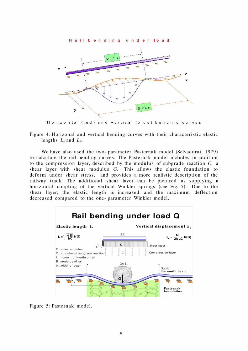
Figure 4: Horizonal and vertical bending curves with their characteristic elasticlengths LH and LV .
We have also used the two- parameter Pasternak model (Selvadurai, 1979)to calculate the rail bending curves. The Pasternak model includes in additionto the compression layer, described by the modulus of subgrade reaction C, ashear layer with shear modulus G. This allows the elastic foundation todeform under shear stress, and provides a more realistic description of therailway track. The additional shear layer can be pictured as supplying ahorizontal coupling of the vertical Winkler springs (see Fig. 5). Due to theshear layer, the elastic length is increased and the maximum deflectiondecreased compared to the one- parameter Winkler model.
Figure 5: Pasternak model.
5
4
bCEI4L = f(G)
�2 L
Rail bending under load QElas tic length L
G...shear modulusC...modulus of subgrade reaction I...moment of inertia of railE...modulus of railb...width of beam
Rail:Bernoulli beam
Pas ternak foundation
Shear layer
Vertical dis placem e nt z 0
z0 = Q
2bLC h(G)
Compression layer
z0
C
E I
G b
Q

2.2 Dynamical loads
When a train is moving, the presence of curves, gradients, and trackimperfections inevitably leads to additional forces ∆Q both in vertical andhorizontal directions. Fig. 6 shows the results of measurements of verticaldynamical wheel loads Q [kN] for two locomotives as a function of the trainvelocity v [km/h]. It is evident that for higher train speeds the dynamicalwheel loads can be as large as 50% of the static vertical wheel load or evenlarger if the train velocity exceeds 200 km/h.
The railway superst ructure must be dimensioned in order to absorb theseadditional forces. In practice this is done by adding velocity dependent safetymargins to the dimensions calculated for static wheel loads. With increasingvertical dynamical loads the horizontal forces also increase. This puts higherdemands on the lateral stiffness of the track. Recent developments aim atupgrading the ballast track for higher speeds and train loads. They have led toinnovative sleeper designs, e. g. broad frame sleepers. This will be brieflydiscussed in sect. 3.
Figure 6: Measured dynamical wheel loads (Birmann, 1967).
In summary, the bearing capacity of a railway structure depends on thestiffness and thickness of the individual elastic layers. For a desired staticwheel load and train velocity the dimensioning of the track is done with thehelp of the Winkler model. In this context, it is important to note thatdifferent countries use different standard axle loads for track dimensioning.In Germany, the standard axle load is 225 kN, whereas the British rail uses 250kN. There is a tendency to push for axle loads of 250 kN in Germany. TheOfotbane in Norway is designed for an axle load of 300 kN (see Fig.7). In theUnited States and Australia, heavy haul trains require railway structures whichcan support static axle loads of 350 kN.
6

Figure 7: A 14- axle locomotive on the Ofotbane between Kiruna and Narvik.
2.3 Bearing capacity classification
A simplified method for dimensioning railway structures was developed bythe UIC. The bearing capacity of a railway structure depends on the bearingcapacity of the substructure. According to the UIC code 719R, the latter isdivided into three classes
� P1 bad � P2 average � P3 good A similar UIC classification exists for the bearing capacity of the naturalfoundation (soil) � QS0 insufficient (e.g. clay) � QS1 bad (e.g. weathered slate) � QS2 average � QS3 good (e.g. granite)
Depedening on the quality of the natural foundation, additional layersmust be introduced and the thicknesses of the various substructure andsuperstructure layers must be increased in order to achieve the desiredbearing capacity and speed of the railway line. The details of the simplifiedcalculational scheme can be found in UIC code 719 R, 1994.
Railway lines are distinguished according to their load bearing capacityaccording to the UIC categories (UIC code 700 V, 1987) shown in Table 1.
7

Table 1: Railway line categories according to their load bearing capacity.
category axle load [kN] vehicle weight /m [kN/m]
A 160 48
B1 180 50
B2 180 64
C2 200 64
C3 200 72
C4 200 80
D2 225 64
D3 225 72
D4 225 80
Further details can be found in Esveld, 2001.
3 MODERN RAILWAY TRACK SYSTEMS
3.1 Ballast track
The elements of a ballast track have already been described in sect. 2. Themain advantages of a ballast track is that its elements are easily accessible andreplaceable. Nowadays, the standard ballast track system in Germany consistsof B70 sleepers and UIC 60 rails. It can be used for axle loads of 225 kN andtrain velocities up to 200 km/h.
The weakest element of a ballast track is the ballast. Due to the sharpedges of the ballast stones, the effective sleeper - ballast contact area is onlyabout 10% of the geometric load support area of the sleepers (Riessberger,2000). This concentration of the load to individual sleeper - ballast contactpoints results locally in very high pressures and leads to a gradual destructionof the ballast particles. To upgrade a ballast track for higher speeds and axleloads of 250 kN, innovative sleeper designs, such as broad frame sleepers havebeen developed (Riessberger, 2000). These frame sleepers increase theeffective load suppor t area and the lateral stiffness of the track.
Another measure to upgrade a ballast track are elastic sleeper footingsand/or sub- ballast mats. The inclusion of these elastic element makes theentire track softer (smaller C) and leads to a better load distribution. Sub-ballast mats also protect the ballast bed from becoming contaminated withfine- grained materials, which would reduce its load distribution capacity. Theuse of rails with broader rail foots in combination with softer baseplate pads(Stahl 1999) has also been proposed. However, there are limits beyond whichballast track would require very high levels of maintenance at relatively shorttime intervals. This becomes apparent at high train velocities.
8
3.2 Slab track systems
At higher train speed v > 200 km/h the wheel- rail interaction leads toincreased vibration emission from the wheel- rail contact zone. Thesevibrations are also transmit ted into the ballast bed, where they cause a highwear of friction. As a result, the ballast bed loses its elasticity. Moreover, atcertain vibration frequencies, the ballast behaves like a liquid and flows outfrom under the sleepers. This leads to a rapid deterioriation of the trackquality and make frequent maintenance, in particular, tamping necessary.
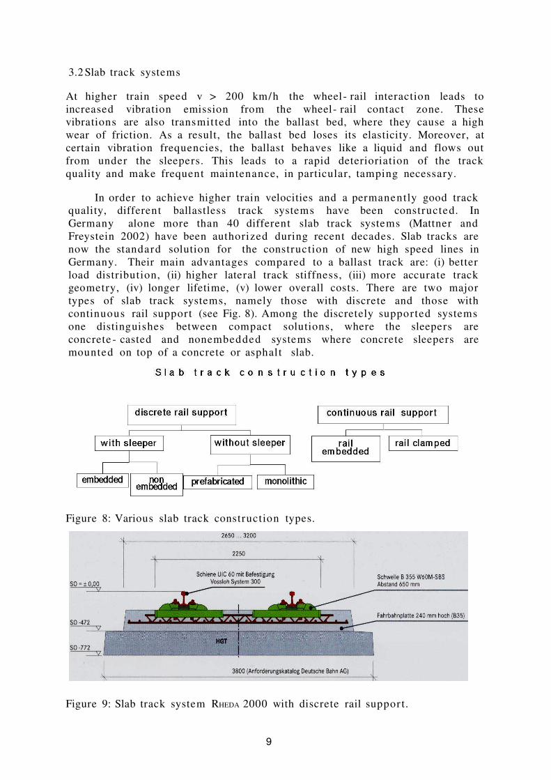
In order to achieve higher train velocities and a permanently good trackquality, different ballastless track systems have been constructed. InGermany alone more than 40 different slab track systems (Mattner andFreystein 2002) have been authorized during recent decades. Slab tracks arenow the standard solution for the construction of new high speed lines inGermany. Their main advantages compared to a ballast track are: (i) betterload distribution, (ii) higher lateral track stiffness, (iii) more accurate trackgeometry, (iv) longer lifetime, (v) lower overall costs. There are two majortypes of slab track systems, namely those with discrete and those withcontinuous rail support (see Fig. 8). Among the discretely supported systemsone distinguishes between compact solutions, where the sleepers areconcrete - casted and nonembedded systems where concrete sleepers aremounted on top of a concrete or asphalt slab.
Figure 8: Various slab track construction types.
Figure 9: Slab track system RHEDA 2000 with discrete rail suppor t.
9

The system RHEDA is currently one of the standard slab track systems inGermany. It belongs to the class of slab track systems with discrete suppor tand embedded sleepers. Since the first Rheda test track was built in 1972,there has been steady progress in improving this system culminating in theRHEDA 2000 system shown in Fig. 9.
Another modern slab track development is the embedded rail system(ERS) INFUNDO. It consists of the following components: (i) rails , which serve asguiding devices and provide load support; corkelast material , which providescontinuous elastic rail support, and vibration damping, (iii) elastic pad , whichprovides the required vertical deflection of the rail, (iv) concrete slab , whichprovides load suppor t and distribution, as well as track gauge stability.
The INFUNDO ERS does not employ bolts, nuts, clamps, or any of the usualrail fastening components. Instead the rails are placed in a concrete troughand fixed by a pourable elastomer material (polyurethan with cork granulate),called corkelast. The corkelast surrounds the rail foot, rail web, and the lowerpart of the rail head. Special adhesives guarantee that rail, corkelast, andconcrete form a tight and permanent connection. The complete embedding ofthe rails in the corkelast material provides continuous elastic rail support, bothin vertical and horizontal direction. Thus the rails are fixed and elasticallysupported over their entire length and not only at discrete points as instandard railway superstructures (see Fig. 10)
Figure 10: INFUNDO embedded railway system
4 ENVIRONMENTAL ISSUES
Railways are crucial for a sustained development of modern societies. Thishas become particularly apparent in recent times. It is widely recognized thatthe shift of freight traffic from rail to road has been accompanied by adverseeffects. Growing pollution and congestion, delays, injuries and death toll areamong the negative consequences resulting from this shift in the modal split.There are clearcut environmental advantages of railways compared with othermodes of transportation.
10
a l l r a i l p r o f i l e s
c o n c r e t e
p i p e
e l a s t i c p a dc o r k e l a s t
Abteilung Eisenbahnwesen Universität Karlsruhe (TH)
continuous rail support
Infundo embedded rail system
####
rails continuously supportedby corkelast
rails continuously embedded in corkelast
concrete slab sound absorbing surface

A major advantage of railway systems is their economic use of theavailable land resources. It is well known that the land use of a double trackrailway system (width 14 m) is considerably lower than a standard four - lanefreeway (width 38 m). In terms of passengers per hour and per meter width oftraffic lane, cars can move about 200 persons, whereas a train can move 9000passengers (Smith, 2003).
There is no debate that railways are a very energy efficient way oftranspor ting passengers and goods. The energy consumption per person andkm of a passenger train is typically a factor 3 lower than for a car. Withrespect to freight traffic the energy use per km and ton of a freight train isabout a factor of 4 lower than for trucks.
Another environmental issue is the noise and vibration emission fromrailway lines. Numerous measurements show that slab track systems havehigher airborne sound emission levels than standard ballast superst ructures.This is partly due to the different sound absorption coefficients of both tracksurfaces, and partly due to constructive differences (e.g. continuous vs.discrete rail support). Because a ballast track surface has a higher soundabsorption coefficient than the concrete surface of a slab track system, oneexpects lower sound emission levels from the former. As an example, we showin Fig. 11 airborne sound measurements made at the double track test site ofthe Deutsche Bahn in Waghäusel near Karlsruhe, where an ERS slab track andadjacent ballast track are tested under normal operation conditions.
Figure 11: Comparison of airborne sound pressure levels [dB] as a function offrequency [Hz] from Infundo ERS and adjacent ballast track measured at adistance of 5.3 m from the ERS track at the Deutsche Bahn test site inWaghäusel.
One also notices that emission spectra of both types of superstructureare different. The spectrum of the INFUNDO ERS has a maximum at around 600Hz where its levels exceeds those of the ballast track by about 10 dB. On the
11
University Professor Dr.- Ing. Eberhard HohneckerHead of the Department of Railway SystemsInst itute for Road and Railway Systems (ISE) University of Karlsruhe (TH)
0
20
40
60
80
100
120
20 31,5
50 80 125
200
315
500
800
1250
2000
3150
5000
8000
12500
20000
frequency [Hz]
sou
nd
pre
ssu
re [d
B]
freight train on ERS freight train on ballast track
DB test site Waghäusel, Germany

other hand, at higher frequencies above 2000 Hz, where the human ear has itshighest sensitivity, the ERS levels are lower than the ballast track by about 7dB. This reduction at higher frequencies leads to the subjective impressionthat train passages over an ERS track sound less annoying. However, whensummed over all frequency bands, the total airborne sound emission levelfrom an ERS is about 5 dB higher than the corresponding ballast track level.Therefore, further improvements of the acoustic properties of the ERS arenecessary. In the case of railbound urban transporta tion systems, thecombination of an ERS with a plant - based track surface reduces the airbornesound levels by about 3 dB and has a positive effect on the urban micro-climate.
5 SUMMARY
In the present paper, I have discussed some features of modern railways.
REFERENCES
Birmann, F., 1967. Messungen am Gleis, Glasers Annalen 91, 263 (1967).
Eisenmann, J. and Mattner, L., 1991. Dimensionierung einer Festen Fahrbahn,EI- Eisenbahningenieur 42, 116 (1991) .
Esveld, C., 1989. Modern Railway Track . MRT- Productions, Duisburg, GermanyFor further details see also Esveld, C. 2001. Modern Railway Track 2 nd
Edition. MRT- Productions, AH Zaltbommel, Netherlands .
Hohnecker, E., 2002. Diskret gelagerte oder kontinuierlich eingebetteteSchienenfahrbahnsysteme. EI- Eisenbahningenieur 53, 45 (2002).
Mattner, L and Freystein, H., 2002. Zulassung von Bauarten im Oberbau durchdas Eisenbahn - Bundesamt , EI- Eisenbahningenieur 53, 5 (2002).
Riessberger, K., 2000. Das Rahmen - Schwellen- Gleis- ein innovativesSchottergleis , ETR 49, 126 (2000).
Selvadurai, A. P. S. , 1979. Elastic analysis of soil- foundation interaction.Elsevier, Amsterdam, 1979.
Smith, R. A., 2003. Railway speed- up: a review of its history, technicaldevelopments and future prospects . Proceedings of the InternationalSymposium on Speed- up and Service Technology for Railway and MaglevSystems 2003, Tokyo, Japan
Stahl, W., 1999. Schotteroberbau für den Hochgeschindigkeitsverkehr, ETR 48,746 (1999).
UIC Kodex 700 V, 1987.
12


