Modem / Router / 4-Port Switch /...
46
Instant Broadband™ Series ADSL Gateway Modem / Router / 4-Port Switch / Wireless-Ready Use this guide to install the following product: BEFDSR41W User Guide
Transcript of Modem / Router / 4-Port Switch /...

Instant Broadband™ Series
ADSL GatewayModem / Router / 4-Port Switch / Wireless-Ready
Use this guide to install the following product:
BEFDSR41W
User Guide
COPYRIGHT & TRADEMARKS Copyright © 2002 Linksys, All Rights Reserved. Instant Broadband is a trademark ofLinksys. Microsoft, Windows, and the Windows logo are registered trademarks ofMicrosoft Corporation. All other trademarks and brand names are the property of theirrespective proprietors.
LIMITED WARRANTY Linksys guarantees that every Instant Broadband ADSL Gateway with Modem / Router /4-Port Switch / Wireless-Ready will be free from physical defects in material and work-manship for one year from the date of purchase, when used within the limits set forth inthe Specifications section of this User Guide. If the product proves defective during thiswarranty period, call Linksys Technical Support in order to obtain a Return Authorizationnumber. BE SURE TO HAVE YOUR PROOF OF PURCHASE ON HAND WHEN CALLING.When returning a product, mark the Return Authorization number clearly on the outsideof the package and include a copy of your original proof of purchase. RETURNREQUESTS CANNOT BE PROCESSED WITHOUT PROOF OF PURCHASE. All cus-tomers located outside of the United States of America and Canada shall be held respon-sible for shipping and handling charges.
IN NO EVENT SHALL LINKSYS’S LIABILITY EXCEED THE PRICE PAID FOR THE PROD-UCT FROM DIRECT, INDIRECT, SPECIAL, INCIDENTAL, OR CONSEQUENTIAL DAM-AGES RESULTING FROM THE USE OF THE PRODUCT, ITS ACCOMPANYING SOFT-WARE, OR ITS DOCUMENTATION. LINKSYS OFFERS NO REFUNDS FOR ITS PROD-UCTS. Linksys makes no warranty or representation, expressed, implied, or statutory,with respect to its products or the contents or use of this documentation and all accom-panying software, and specifically disclaims its quality, performance, merchantability, orfitness for any particular purpose. Linksys reserves the right to revise or update its prod-ucts, software, or documentation without obligation to notify any individual or entity.Please direct all inquiries to:
Linksys P.O. Box 18558, Irvine, CA 92623.
FCC PART 15 CLASS B STATEMENTIn compliance with the Federal Communications Commission (FCC), the following FCCPart 15 Regulations are provided regarding the installation and operation of the LinksysBEFDSR41W ADSL Gateway.
This equipment has been tested and found to comply with the limits for a Class B digitaldevice, pursuant to Part 15 of the FCC Rules. These limits are designed to provide rea-sonable protection against harmful interference in a residential installation.
This equipment generates, uses and can radiate radio frequency energy and, if notinstalled and used in accordance with the instructions, may cause harmful interferenceto radio communications. However, there is no guarantee that interference will not occurin a particular installation. If this equipment does cause harmful interference to radio ortelevision reception, which can be determined by turning the equipment off and on, theuser is encouraged to try to correct the interference by one or more of the followingmeasures:

• Reorient or relocate the receiving antenna.• Increase the separation between the equipment and the receiver.• Connect the equipment to an outlet on a circuit different from that to which the receiv-
er is connected.• Consult a dealer or an experienced radio/TV technician for assistance.
This device complies with Part 15 of the FCC Rules. Operation is subject to the follow-ing two conditions:
• This device may not cause harmful interference.• This device must accept any interference received, including interference that may
cause undesired operation.
FCC PART 68 STATEMENTThis equipment complies with Part 68 of the FCC Rules. A label is attached to the equip-ment that contains, among other information, its FCC registration number and ringerequivalence number. If requested, this information must be provided to the telephonecompany.
This equipment uses the following USOC Jack: RJ-11.
An FCC compliant telephone cord and modular plug is provided with this equipment.This equipment is designed to be connected to the telephone network or premises wiringusing a compatible modular jack, which is FCC Part 68 compliant. Connection to thetelephone network should be made by using the standard modular telephone jack.
The REN is useful to determine the quantity of devices that may be connected to the tele-phone line and still have all of those devices ring when your telephone number is called.In most, but not all areas, the sum of RENs should not exceed 5. To be certain of thenumber of devices that may be connected to the line, as determined by the total RENs,contact the telephone company to determine the maximum REN for the calling area.
If this equipment causes harm to the telephone network, the telephone company maydiscontinue your service temporarily. If advance notice is not practical, the telephonecompany will notify the customer as soon as possible. Also, you will be advised of yourright to file a complaint with the FCC if you believe it is necessary.
The telephone company may make changes in its facilities, equipment, operations, orprocedures that could affect the operation of the equipment. If this happens, the tele-phone company will provide advance notice in order for you to make the necessary mod-ifications in order to maintain uninterrupted service.
In the event this equipment should fail to operate properly, disconnect the unit from thetelephone line. Try using another FCC approved device in the same telephone jack. Ifthe trouble persists, call the telephone company repair service bureau. If the troubledoes not persist and appears to be with this unit, disconnect the unit from the telephoneline and discontinue use of the unit until it is repaired. Please note that the telephonecompany may ask that you disconnect the equipment from the telephone network untilthe problem has been corrected or until you are sure that the equipment is not malfunc-tioning. The user must use the accessories and cables supplied by the manufacturer toget optimum performance from the product.
No repairs may be done by the customer. If trouble is experienced with this equipment,please contact your authorized support provider for repair and warranty information. Ifthe trouble is causing harm to the telephone network, the telephone company mayrequest you remove the equipment from the network until the problem is resolved. Thisequipment cannot be used on telephone company provided coin service. Connection toParty Line Service is subject to state tariffs.
SAFETY NOTICES• Caution: To reduce the risk of fire, use only No.26 AWG or larger telecommunication
line cord.
• Do not use this product near water, for example, in a wet basement or near a swim-ming pool.
• Avoid using this products (other than a cordless type) during an electrical storm.There may be a remote risk of electric shock from lightning.
UG-BEFDSR41W-071802NC-BW

ADSL Gateway with Modem / Router / 4-Port Switch / Wireless-Ready
Filtering 47Forwarding 49Dynamic Routing 51Static Routing 53DMZ Host 55Firewall 56Link Test 57
Appendix A: Troubleshooting 58Common Problems and Solutions 58Frequently Asked Questions 60
Appendix B: Configuring Wireless Security 64Configuring Wireless Security in Windows XP 68
Appendix C: Installing the TCP/IP Protocol 73
Appendix D: Finding the MAC Address and IPAddress for Your Ethernet Adapter 75
Appendix E: Specifications 79Environmental Specifications 80
Appendix F: Warranty Information 81
Appendix G: Contact Information 82
Instant Broadband™ Series
Table of ContentsChapter 1: Introduction 1
The Linksys ADSL Gateway with Modem / Router / 4-Port Switch / Wireless-Ready 1Features 1Package Contents 2Minimum Requirements 2An Introduction to LANs and WANs 2IP Addresses 3Network Setup Overview 5
Chapter 2: Getting to Know the ADSL Gatewaywith Modem / Router / 4-Port Switch / Wireless-Ready 6
The Gateway’s Back Panel Ports 6The Gateway’s Front Panel LEDs 7
Chapter 3: Connecting the Gateway 9
Chapter 4: Configuring the PCs 12Overview 12Windows 95, Windows 98, Windows Millennium 13Windows 2000 15Windows XP 17
Chapter 5: Configuring the Gateway 19
Chapter 6: Using the Gateway’s Web-basedUtility 25
Quick and Easy Gateway Administration 25Setup 26Password 34Status 36DHCP 38Log 40UPnP 41Help 42Wireless 44Advanced 46

Instant Broadband™ Series ADSL Gateway with Modem / Router / 4-Port Switch / Wireless-Ready
Chapter 1: Introduction
Thank you for choosing the Instant Broadband™ ADSL Gateway with Modem / Router / 4-Port Switch / Wireless-Ready. This Gateway allows you to set up a network with your PCsand share your Internet connection.
The Gateway does this by connecting to your ADSL line, and using the Gateway’s Ethernetports to connect your PCs; it’s like each PC is connected directly to the Internet. This way, youhave an Ethernet network where you have several PCs utilizing one Internet connection simul-taneously. Plus, if you add a Linksys wireless PC Card, it can be used as an Access Point andthe Gateway can bridge your Ethernet network with your wireless PCs.
The PCs that you connect to the Gateway’s four LAN ports, when properly configured, cre-ate a LAN, or Local Area Network. They are connected with an Ethernet cable plugged intoyour computer’s Ethernet adapter at one end and into one of the Gateway's LAN ports (num-bered from one to four) at the other end. The term “Ethernet” is used to refer to your networkaccessories, such as cables and adapters, because Ethernet refers to the type of network thatyou are setting up. Ethernet refers to the accessories that transfer computer data from 10Mbpsto 100Mbps (speeds used by network devices.)
The Gateway allows you to share your ADSL connection using a built-in ADSL modem, andcan plug directly into your ADSL-enabled wall jack (DSL service line). The PCs that are con-nected to the Gateway share this connection.
• Download Speeds of up to 8Mbps • Upload Speeds of up to 800kbps• Prevents DoS (Denial of Service) Attacks• E-mail and Web-based Logging of Security Events• MAC Address Filtering, Port Forwarding, DMZ Support• Configurable through Your Networked PC’s Web Browser• Supports VPN Pass-Through for IPSec, PPTP, and L2TP Protocols• Internal 4-Port Switch Dramatically Speeds Up Your Network• DHCP Server Capability to Assign IP Addresses Automatically• Wireless Capabilities Available with Use of Optional WPC11 (sold separately)
• Supports a High Data Rate of up to 11Mbps for up to 28 SimultaneousWireless Connections
• Capable of 64 and 128-Bit WEP Encryption• Compliant with ANSI T1.413i2, ITU-T G.dmt (G.992.1), and ITU G.lite
(G.992.2) Standards• Supports RFC 1483, RFC 2364 PPPoA, RFC 2516 PPPoE Protocols
1
The Linksys ADSL Gateway with Modem / Router / 4-Port Switch / Wireless-Ready
Features

ADSL Gateway with Modem / Router / 4-Port Switch / Wireless-Ready
3
Think of the Gateway as a network device with two sides: the first side is madeup of your private Local Area Network (LAN) of PCs. The other, public side isthe Internet, or the Wide Area Network (WAN), outside of your home or office.
The Gateway’s firewall (NAT) protects your network of PCs so users on thepublic, Internet side cannot “see” your PCs. This is how your LAN, or network,remains private. The Gateway protects your network by inspecting the firstpacket coming in through the WAN port before delivery to the final destinationon the LAN port. The Gateway inspects Internet port services like the web serv-er, ftp server, or other Internet applications, and, if allowed, it will forward thepacket to the appropriate PC on the LAN side.
What’s an IP Address?IP stands for Internet Protocol. Every device on an IP-based network, includingPCs, print servers, and routers, requires an IP address to identify its “location,”or address, on the network. This applies to both the WAN and LAN connections.There are two ways of assigning an IP address to your network devices.
Static IP AddressesA static IP address is a fixed IP address that you assign manually to a PC orother device on the network. Since a static IP address remains valid until youdisable it, static IP addressing ensures that the device assigned it will alwayshave that same IP address until you change it. Static IP addresses are com-monly used with network devices such as server PCs or print servers.
When using the Gateway to share your ADSL Internet connection, contact yourISP to find out if they have assigned a static IP address to your account. If so,you will need that static IP address when configuring the Gateway. You can getthe information from your ISP.
IP Addresses
Note: Since the Gateway is a device that connects two networks, itneeds two IP addresses—one for the LAN side, and one for the WANside. In this User Guide, you’ll see references to the “WAN IPaddress” and the “LAN IP address.”
Since the Gateway has firewall security (NAT), the only IP address thatcan be seen from the Internet for your network is the Gateway’s WANIP address.
However, even this WAN IP address for the Gateway can be blocked,so that the Gateway and network seem invisible to the Internet—seethe IP Filtering section in “Chapter 6: Using the Gateway’s Web-basedUtility.”
Instant Broadband™ Series
2
• One ADSL Gateway with Modem / Router / 4-Port Switch / Wireless-Ready
• One Power Adapter• One RJ-11 Phone Cable• One User Guide• One Fast Start and Registration Card (not shown)
• Network Adapter with Ethernet (UTP CAT 5) Cabling and TCP/IP ProtocolInstalled per PC
• Internet Explorer 4.0 or Netscape Navigator 4.7 or Higher for Web-basedConfiguration
• ADSL Connection and Activated Account• Optional Wireless Network PC Card Model WPC11 for Wireless Connection
(sold separately)
Simply put, a router is a network device that connects two networks together.
In this instance, the Gateway connects your Local Area Network (LAN), orthe group of PCs in your home or office, to the Wide Area Network (WAN),that is, the Internet. The Gateway processes and regulates the data that travelsbetween these two networks.
Minimum Requirements
Package Contents
Figure 1-1
An Introduction to LANs and WANs

ADSL Gateway with Modem / Router / 4-Port Switch / Wireless-Ready
This user guide covers the basic steps for setting up a network with a Gateway.After going through the “Getting to Know the Gateway” chapter, most userswill only need to use the following chapters:
• Chapter 3: Connecting the GatewayThis chapter instructs you on how to connect the ADSL line to the Gatewayand connect the PC(s) to the Gateway.
• Chapter 4: Configuring the PCsThis chapter instructs you on how to configure your PC(s) for a DHCP con-nection, if the network settings are not already set to DHCP.
• Chapter 5: Configuring the GatewayThis chapter explains how to configure the Gateway using your web browserand the Gateway’s web-based utility. You will configure the Gateway usingthe settings provided by your ISP.
When you’re finished with the basic steps, then you are ready to connect to theInternet. After the PC(s) can access the Internet through the Gateway, you canalter the Gateway’s settings further; for example, you can adjust security fea-tures and other settings to enable online gaming, run Internet servers, config-ure a wireless LAN (WPC11 required) and more!
5
Instant Broadband™ Series
Dynamic IP AddressesA dynamic IP address is automatically assigned to a device on the network,such as PCs and print servers. These IP addresses are called “dynamic”because they are only temporarily assigned to the PC or device. After a certaintime period, they expire and may change. If a PC logs onto the network (or theInternet) and its dynamic IP address has expired, the DHCP server will assignit a new dynamic IP address.
For ADSL users, many ISPs may require you to log on with a user name andpassword to gain access to the Internet. This is a dedicated, high-speed con-nection type called Point to Point Protocol over Ethernet (PPPoE). PPPoE issimilar to a dial-up connection, but PPPoE does not dial a phone number whenestablishing a connection. PPPoE also will provide the Gateway with a dynam-ic IP address to establish a connection to the Internet. Point to Point Protocolover ATM, or PPPoA, is a similar login method also used for some ADSL con-nections.
DHCP (Dynamic Host Configuration Protocol) ServersDHCP frees you from having to assign IP addresses manually every time a newuser is added to your network. PCs and other network devices using dynamicIP addressing are assigned a new IP address by a DHCP server. The PC or net-work device obtaining an IP address is called the DHCP client. By default, theGateway’s WAN setting is DHCP client.
A DHCP server can either be a designated PC on the network or another net-work device, such as the Gateway. By default, a DHCP server (LAN side) isenabled on the Gateway. If you already have a DHCP server running on yournetwork, you must disable one of the two DHCP servers. If you run more thanone DHCP server on your network, you will experience network errors, such asconflicting IP addresses. To disable DHCP on the Gateway, see the DHCP sec-tion in “Chapter 6: Using the Gateway’s Web-based Utility.”
4
Note: Even if you assign a static IP address to a PC, other PCs canstill use DHCP’s dynamic IP addressing, as long as the static IPaddress is not within the DHCP range of the LAN IP Address.
If the dynamic IP addressing fails to provide a dynamic IP address,refer to “Appendix A: Troubleshooting.”
Network Setup Overview
Notebook with Ethernet Adapter
ADSL Gatewaywith Modem / Router / 4-Port
Switch / Wireless-Ready
LAN
PC with Ethernet Adapter
WAN

ADSL Gateway with Modem / Router / 4-Port Switch / Wireless-Ready
7
Instant Broadband™ Series
6
Power Green. The Power LED lights up when the Gateway is pow-ered on.
Diag Green. The Diag LED flashes when the Gateway is bootingup. If this flashes or stays solid after the bootup phase, theGateway may be malfunctioning. See “Appendix A:Troubleshooting” if you encounter this problem.
Link/Act Green. The Link/Act LED serves two purposes. If the LEDis continuously lit, the Gateway is successfully connected toa device through the corresponding port (1, 2, 3 or 4). If theLED is flickering, the Gateway is actively sending or receiv-ing data over that port.
Full/Col Green. The Full/Col LED also serves two purposes. If thisLED is lit up continuously, the connection made through thecorresponding port is running in Full Duplex mode. If theLED flickers, the connection is experiencing collisions.Infrequent collisions are normal.
100 Green. The 100 LED lights up when a successful 100Mbpsconnection is made through the corresponding port.
If this LED does not light up, then your connection speed is10 Mbps.
WLAN Link Green. This LED is solidly lit when a wireless PC Card isinserted and functioning in the Gateway.
WLAN Act Green. This LED flashes when there is wireless activity.
The Gateway’s Front Panel LEDs
Figure 2-2
Chapter 2: Getting to Know theADSL Gateway with Modem / Router / 4-Port Switch / Wireless-Ready
The Gateway’s ports, where network cables are connected, are located on theback panel of the Gateway.
ADSL The ADSL port is where you will connect yourADSL line.
Ports 1-4 These four LAN (Local Area Network) ports con-nect to network devices, such as PCs, print servers,and remote hard drives.
Power The Power port is where you will connect thepower adapter.
On/Off Switch This switch is used for turning the Gateway on andoff.
PC Card Slot This is where you can connect the optional wirelessPC card (not included) for wireless features.
The Gateway’s Back Panel Ports
Figure 2-1

ADSL Gateway with Modem / Router / 4-Port Switch / Wireless-Ready
9
Instant Broadband™ Series
8
Chapter 3: Connecting theGateway
You will connect the Gateway to your ADSL line and to the computers in yourhome or business.
First, make sure that all the devices that you’ll be working with are powereddown, including your PCs and the Gateway.
1. Connect one end of the provided phone cable to the ADSL (RJ-11 phone)port that is on the back of the Gateway.
2. Connect the other end of the phone cable to the wall jack with ADSL service.
ADSL Session Green. This LED is solidly lit when a PPPoE session is estab-lished.
ADSL Link Green. This LED is off when an ADSL line is not detected.It flashes when the Gateway is attempting to make an ADSLconnection. The LED is solidly lit when an ADSL connectionhas been successfully established.
ADSL Act Green. This LED flashes when there is activity across theADSL connection.
Proceed to “Chapter 3: Connecting the Gateway.”
Connecting Your Hardware and Booting Up
Figure 3-1
Figure 3-2
The Reset Button
Briefly pressing the Reset Button or rebooting the Gateway will refresh theGateway’s connections. If the Gateway locks up, simply press the Reset Buttonor power it down for three to five seconds. Leaving the power off for too longcould result in the loss of network connections.
Pressing the Reset Button and holding it in for a few seconds will clear all ofthe Gateway’s data and restore the factory defaults. This should be done onlyif you are experiencing heavy routing problems, and only after you haveexhausted all of the other troubleshooting options. By resetting the Gateway,you run the risk of creating conflicts between your PCs’ actual IP Addressesand what the Gateway thinks their IP Addresses should be. You may be forcedto reboot each network PC.

ADSL Gateway with Modem / Router / 4-Port Switch / Wireless-Ready
11
Instant Broadband™ Series
10
4. Connect the power adapter to the Gateway. Plug the power adapter into theelectrical outlet.
5. Turn on the Gateway. Then, turn on the first PC that you want to use to con-figure the Gateway.
Go to “Chapter 4: Configuring the PCs.”
3. Connect one end of an Ethernet cable to your PC’s Ethernet adapter. Connectthe other end of the cable to one of the LAN ports on the back of the Gateway.Repeat this process for every PC that you want to connect to the Gateway.
Note: If your PC’s Ethernet adapter is not set up, please refer to the Ethernetadapter’s user guide for more information.
If you are connecting more than four PCs to the Gateway, you will also needto connect a hub or switch to the Gateway.
Figure 3-3
Figure 3-4
Figure 3-5
Figure 3-6
Note: The ADSL Gateway (with optional WPC11) is configured bydefault to work out of the box with all Linksys Wireless Adapters. Ifyou have changed the defaults on your Linksys Wireless Adapters, orare using other wireless adapters, you must temporarily change yourwireless adapter settings to: (SSID = linksys) in order to initiallyaccess the Gateway wirelessly. After you have accessed the Gatewaywith the default settings, you can change the Gateway settings to coin-cide with your Network settings and reset your adapters.
Note: A small device called a microfilter (not included) may be nec-essary between each phone and wall jack to prevent interference.Contact your ISP if you have any questions.
Note: If you have a Linksys wireless PC Card (WPC11), be sure tofully insert it into the PC Card slot on the back of the Gateway beforeturning on the power. You must have this card inserted in order touse the Gateway's wireless features.

ADSL Gateway with Modem / Router / 4-Port Switch / Wireless-Ready
1. Go to the Network screen by clicking the Start button. Click Settings andthen Control Panel. From there, double-click the Network icon.
2. On the Configuration tab, select the TCP/IP line for the applicableEthernet adapter. Do not choose a TCP/IP entry whose name mentionsDUN, PPPoE, VPN, or AOL. If the word TCP/IP appears by itself, selectthat line. (If there is no TCP/IP line listed, refer to “Appendix C: Installingthe TCP/IP Protocol” or your Ethernet adapter’s user guide to installTCP/IP now.) Click the Properties button.
13
Instant Broadband™ Series
Chapter 4: Configuring the PCs
The instructions in this chapter will help you configure each of your comput-ers to be able to communicate with the Gateway.
To do this, you need to configure your PC’s network settings to obtain an IP (orTCP/IP) address automatically (called DHCP). Computers use IP addresses tocommunicate with each other across a network or the Internet.
You will need to know which operating system your computer is running, suchas Windows 95, 98, Millennium, 2000, or XP. One way to find out which oper-ating system you have is by clicking the Start button and then going to theSettings option. Then click Control Panel, and then double-click the Systemicon.
You may need to do this for each computer you are connecting to the Gateway.
The next few pages tell you, step by step, how to configure your network set-tings based on the type of Windows operating system you are using.
If your operating system is not referenced here, refer to your operating systemdocumentation.
Once you've configured your computers, continue to “Chapter 5: Configuringthe Gateway.”
12
Figure 4-1
Windows 95, Windows 98, Windows Millennium
Overview

ADSL Gateway with Modem / Router / 4-Port Switch / Wireless-Ready
1. Go to the Network screen by clicking the Start button. Click Settings andthen Control Panel. From there, double-click the Network and Dial-upConnections icon.
2. Select the Local Area Connection icon for the applicable Ethernet adapter(usually it is the first Local Area Connection listed). Do not choose aTCP/IP entry whose name mentions DUN, PPPoE, VPN, or AOL. Double-click the Local Area Connection.
3. The Local Area Connection Status screen will appear. Click the Propertiesbutton.
15
Instant Broadband™ Series
3. Click the IP Address tab. Select Obtain an IP address automatically.
4. Now click the Gateway tab to ensure that the Installed Gateway field is leftblank. Click the OK button.
5. Click the OK button again. Windows may ask you for the originalWindows installation disk or additional files. Supply them by pointing tothe correct file location, e.g., D:\win98, D:\win9x,c:\windows\options\cabs, etc. (if “D” is the letter of your CD-ROM drive).
6. Windows may ask you to restart your PC. Click the Yes button. If Windowsdoes not ask you to restart, restart your computer anyway.
Go to “Chapter 5: Configuring the Gateway.”
14
Windows 2000
Figure 4-3
Figure 4-2

ADSL Gateway with Modem / Router / 4-Port Switch / Wireless-Ready
The following instructions assume you are running Windows XP with thedefault interface. If you are using the Classic interface (where the icons andmenus look like previous Windows versions), please follow the instructions forWindows 2000.
1. Click to the Network screen by clicking the Start button and then ControlPanel. From there, click the Network and Internet Connections icon andthen the Network Connections icon.
2. Select the Local Area Connection icon for the applicable Ethernet adapter(usually it is the first Local Area Connection listed). Double-click theLocal Area Connection. Click the Properties button.
3. The Local Area Connection Status screen will appear. Click the Propertiesbutton.
17
Instant Broadband™ Series
4. Select Internet Protocol (TCP/IP), and click the Properties button.
5. Select Obtain an IP address automatically. Once the new windowappears, click the OK button. Click the OK button again to complete thePC configuration.
6. Restart your computer.
Go to “Chapter 5: Configuring the Gateway.”
16
Windows XP
Figure 4-6
Figure 4-4
Figure 4-5

ADSL Gateway with Modem / Router / 4-Port Switch / Wireless-Ready
Chapter 5: Configuring theGateway
In this chapter, you will configure the Linksys ADSL Gateway to be able togain access to the Internet through your Internet Service Provider (ISP). Youwill need the setup information provided by your ADSL ISP:
• Your ADSL line VPI and VCI• Your ADSL encapsulation type and multiplexing
For PPPoA or PPPoE users, you also need these values from your ISP:• Your username and password
For RFC 1483 users, you may need these values from your ISP:• Your ADSL fixed Internet IP address • Your Subnet Mask• Your Default Gateway• Your primary DNS IP address
The above information should have been provided by your ADSL ISP. If not, contactyour ISP and they will be able to supply you with the correct settings. The instructionsfrom your ISP tell you how to set up your PC for Internet access. Because youare now using the Gateway to share Internet access among several computers,you will use the setup information to configure the Gateway instead of yourPC. You only need to configure the Gateway once using the first computer youset up.
19
Instant Broadband™ Series
4. Select Internet Protocol (TCP/IP), and click the Properties button.
5. Select Obtain an IP address automatically. Once the new windowappears, click the OK button. Click the OK button again (or the Close but-ton if any settings were changed) to complete the PC configuration.
6. Restart your computer.
Go to “Chapter 5: Configuring the Gateway.”
18
Figure 4-7
Figure 4-8
Configuring the Gateway
Figure 5-1

ADSL Gateway with Modem / Router / 4-Port Switch / Wireless-Ready
21
Instant Broadband™ Series
20
4. The Gateway supports five modes of Encapsulation: RFC 1483 Bridged,RFC 1483 Routed, RFC2364 PPPoA, RFC2516 PPPoE, and Bridged ModeOnly. These modes are listed in the drop-down menu for the Encapsulationsetting. Each Setup screen and available features will differ depending onwhat kind of connection mode you select. The instructions for RFC 1483Bridged, RFC2516 PPPoE, and RFC2364 PPPoA are listed below; if theinstructions for your connection mode is not explained here, then proceedto “Chapter 6: Using the Gateway’s Web Based Utility.”
A. RFC 1483 Bridged
This mode supports two types of WAN IP Addresses: Dynamic IP Address orStatic IP Address. Follow the directions for the type of WAN IP Address youneed to use.
Dynamic IP Address
If your ISP says that you are connecting through a dynamic IP address, fol-low these steps:
1. Select Dynamic IP Address as the WAN IP Address.
2. Click the Apply and Continue buttons to save the settings.
1. Open your web browser. (It is all right if you get an error message at thispoint. Continue following these directions.) Enter http://192.168.1.1 in theweb browser’s Address field. Press the Enter key.
2. An Enter Network Password window, shown in Figure 5-3, will appear(Windows XP users will see a Connect to 192.168.1.1 window, shown inFigure 5-4). Enter admin in lowercase letters in the User Name field, andenter admin in lowercase letters in the Password field (admin is the defaultuser name and password). Then, click the OK button.
3. The Gateway configuration screen will appear with the Setup tab selected.Based on the setup instructions from your ISP, you may need to provide thefollowing information.
Host Name and Domain Name These fields allow you to provide a hostname and domain name for the Gateway. These fields are usually left blank.If requested by your ISP, complete these two fields.
Virtual Circuit ID (VPI and VCI) These fields consist of two items: VPI(Virtual Path Identifier) and VCI (Virtual Channel Identifier). Your ISPwill provide the correct settings for this field.
Figure 5-2
Figure 5-3 Figure 5-4
Figure 5-5
ADSL Gateway with Modem / Router / 4-Port Switch / Wireless-Ready
23
Instant Broadband™ Series
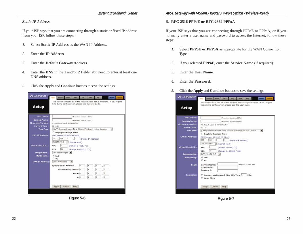
Static IP Address
If your ISP says that you are connecting through a static or fixed IP addressfrom your ISP, follow these steps:
1. Select Static IP Address as the WAN IP Address.
2. Enter the IP Address.
3. Enter the Default Gateway Address.
4. Enter the DNS in the 1 and/or 2 fields. You need to enter at least one DNS address.
5. Click the Apply and Continue buttons to save the settings.
22
B. RFC 2516 PPPoE or RFC 2364 PPPoA
If your ISP says that you are connecting through PPPoE or PPPoA, or if younormally enter a user name and password to access the Internet, follow thesesteps:
1. Select PPPoE or PPPoA as appropriate for the WAN Connection Type.
2. If you selected PPPoE, enter the Service Name (if required).
3. Enter the User Name.
4. Enter the Password.
5. Click the Apply and Continue buttons to save the settings.
Figure 5-7Figure 5-6

ADSL Gateway with Modem / Router / 4-Port Switch / Wireless-Ready
Chapter 6: Using the Gateway’sWeb-based Utility
For your convenience, an administrative utility has been programmed into theGateway where all Gateway-based administrative tasks are performed. Thischapter will explain all of the functions in this utility. The web utility can beaccessed by an PC on the network by typing the Gateway’s default IP address192.168.1.1 in the PC’s web browser address window, as shown in Figure 6-1.Press the Enter key.
An Enter Network Password window, shown in Figure 6-2, will appear(Windows XP users will see a Connect to 192.168.1.1 window, shown in Figure6-3). Enter admin in lowercase letters in the User Name field, and enter adminin lowercase letters in the Password field (admin is the default user name andpassword). Then, click the OK button.
In the following sections, you’ll find brief descriptions of each web page in theutility and each page’s key functions. More detailed explanations and instruc-tions can be found by clicking each page’s Help button or on Linksys’s websiteat www.linksys.com To apply any of the settings you change on a page, clickthe Apply button, and then click the Continue button. To cancel any valuesyou’ve entered on any page, click the Cancel button.
25
Instant Broadband™ Series
24
Quick and Easy Gateway Administration
Figure 6-1
5. If you haven’t already done so, click the Apply button and then theContinue button to save your Setup settings. Close the web browser.
6. Congratulations! You’ve suc-cessfully configured theGateway. Test the setup byopening your web browserfrom any computer and entering www.linksys.com/registration.
If you need advanced setting information, please refer to “Chapter 6: Usingthe Gateway’s Web-Based Utility” or the Linksys support website atsupport.linksys.com.
If you are unable to reach our website, you may want to review what youdid in this section or refer to “Appendix A: Troubleshooting.”
Go to “Chapter 6: Using the Gateway’s Web-based Utility” for moredetails and advanced settings information.
Figure 5-8
Figure 6-2 Figure 6-3

ADSL Gateway with Modem / Router / 4-Port Switch / Wireless-Ready
• Encapsulation The Gateway supports five encapsulation modes: RFC1483 Bridged, RFC 1483 Routed, RFC 2364 PPPoA, RFC2516 PPPoE,and Bridged Mode Only. These modes can be selected from the drop-downmenu next to the Encapsulation setting. Each Setup screen and availablefeatures will differ depending on what kind of connection mode you select.Each mode is described on the following pages.
• Multiplexing The Gateway supports both VC and LLC multiplexing. YourISP will provide the correct selection for this setting.
27
Instant Broadband™ Series
The Setup screen is the first screen you see when you access the web-basedutility. If you have already installed and set up the Gateway, you have alreadyseen this screen and properly configured each of the values.
• Host Name & Domain Name These fields allow you to supply a host anddomain name for the Gateway. Some ISPs require these names as identifi-cation. You may have to check with your ISP to see if your broadbandInternet service has been configured with a host and domain name. In mostcases, leaving these fields blank will work.
• Firmware Version This entry shows the version and date of the firmwareyou are using. Future versions of the Gateway’s firmware will be posted andavailable for download on the Linksys website at www.linksys.com.
• Current Time The Gateway will try to reach an Internet timeserver and dis-play the current time in this location. If a timesaver cannot be reached, thiswill show the time elapsed since the Gateway was powered on.
• Time Zone Set your local time zone in this field. If your region participatesin Daylight Savings Time (DST), check the box next to Daylight SavingsTime.
• LAN IP Address and Subnet Mask The values for the Gateway’s IPAddress and Subnet Mask as seen on the internal LAN are shown here. Thedefault values are 192.168.1.1 for the Device IP Address and 255.255.255.0for the Subnet Mask.
• Virtual Circuit ID These fields consist of two items: VPI (Virtual PathIdentifier) and VCI (Virtual Channel Identifier). Your ISP will provide thecorrect settings for these fields.
VPI Enter the number provided by your ISP. The number will be in therange of 0 to 255.
VCI Enter the number provided by your ISP. The number will be in therange of 0 to 65535.
26
Note: After setup, you can test and see if the settings are correct bysuccessfully connecting to the Internet.
Figure 6-4
Setup
Note: The screen you see may vary depending on what kind of con-nection mode you select.
ADSL Gateway with Modem / Router / 4-Port Switch / Wireless-Ready
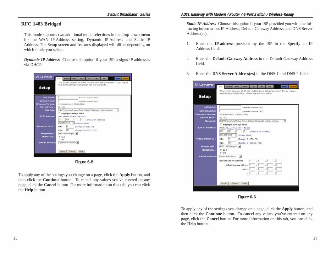
Static IP Address Choose this option if your ISP provided you with the fol-lowing information: IP Address, Default Gateway Address, and DNS ServerAddress(es).
1. Enter the IP address provided by the ISP in the Specify an IPAddress field.
2. Enter the Default Gateway Address in the Default Gateway Addressfield.
3. Enter the DNS Server Address(es) in the DNS 1 and DNS 2 fields.
To apply any of the settings you change on a page, click the Apply button, andthen click the Continue button. To cancel any values you’ve entered on anypage, click the Cancel button. For more information on this tab, you can clickthe Help button.
29
Instant Broadband™ Series
RFC 1483 Bridged
This mode supports two additional mode selections in the drop-down menufor the WAN IP Address setting, Dynamic IP Address and Static IPAddress. The Setup screen and features displayed will differ depending onwhich mode you select.
Dynamic IP Address Choose this option if your ISP assigns IP addressesvia DHCP.
To apply any of the settings you change on a page, click the Apply button, andthen click the Continue button. To cancel any values you’ve entered on anypage, click the Cancel button. For more information on this tab, you can clickthe Help button.
28
Figure 6-5
Figure 6-6

ADSL Gateway with Modem / Router / 4-Port Switch / Wireless-Ready
31
Instant Broadband™ Series
30
RFC 2364 PPPoA
Choose this option if your ISP told you to use this mode of encapsulation.Use the User Name and Password provided by your ISP.
1. Enter the User Name in the Specify an IP Address field.
2. Enter the Password in the Password field.
3. Choose either Connect on Demand or Keep Alive to determine howthe Gateway will maintain your Internet connection during any periodof inactivity. If you have been disconnected due to inactivity, Connecton Demand enables the Gateway to automatically re-establish yourconnection as soon as you attempt to access the Internet again. You canconfigure the Gateway to cut your connection with your ISP after aspecific period of time (Max Idle Time). The Keep Alive option keepsyour Internet Access connected indefinitely, even when it sits idle.
To apply any of the settings you change on a page, click the Apply button, andthen click the Continue button. To cancel any values you’ve entered on anypage, click the Cancel button. For more information on this tab, you can clickthe Help button.
Figure 6-8
RFC 1483 Routed
Choose this option if your ISP told you to use this mode of encapsulation.Use the IP address and DNS Server Address(es) provided by your ISP.
1. Enter the IP address provided by the ISP in the Specify an IPAddress field.
2. Enter the DNS Server Address(es) in the DNS 1 and DNS 2 fields.
To apply any of the settings you change on a page, click the Apply button, andthen click the Continue button. To cancel any values you’ve entered on anypage, click the Cancel button. For more information on this tab, you can clickthe Help button.
Figure 6-7

ADSL Gateway with Modem / Router / 4-Port Switch / Wireless-Ready
33
Instant Broadband™ Series
32
Bridged Mode Only
Choose this option if your ISP told you to use this mode of encapsulation.This mode is used to configure the Gateway as an RFC1483 bridge, when theGateway’s routing and NAT capabilities need to be disabled.
To apply any of the settings you change on a page, click the Apply button, andthen click the Continue button. To cancel any values you’ve entered on anypage, click the Cancel button. For more information on this tab, you can clickthe Help button.
Figure 6-10
RFC 2516 PPPoE
Choose this option if your ISP told you to use this mode of encapsulation.Use the User Name, Password, and Service Name (if applicable) provided byyour ISP.
1. Enter the Service Name (if provided) in the field.
2. Enter the User Name in the Specify an IP Address field.
3. Enter the Password in the Password field.
4. Choose either Connect on Demand or Keep Alive to determine how the Gateway will maintain your Internet connection during any periodof inactivity. If you have been disconnected due to inactivity, Connecton Demand enables the Gateway to automatically re-establish yourconnection as soon as you attempt to access the Internet again. You canconfigure the Gateway to cut your connection with your ISP after aspecified period of time (Max Idle Time). The Keep Alive option keepsyour Internet access connected indefinitely, even when it sits idle.
To apply any of the settings you change on a page, click the Apply button, andthen click the Continue button. To cancel any values you’ve entered on anypage, click the Cancel button. For more information on this tab, you can clickthe Help button.
Figure 6-9

ADSL Gateway with Modem / Router / 4-Port Switch / Wireless-Ready
35
Instant Broadband™ Series
34
• SNMP Trap Community Enter the password sent with each trap to theSNMP manager.
• SNMP Trap Destination Enter the IP address of the station that receivesthe SNMP traps sent by the Gateway.
• Restore Factory Defaults If you select the Restore Factory Defaults optionand click the Apply button, you will clear all of the Gateway’s settings.
Do not restore the factory defaults unless you are having difficulties withthe Gateway and have exhausted all other troubleshooting measures. Oncethe Gateway is reset, you will have to re-enter all of your configuration data.
To apply any of the settings you change on a page, click the Apply button, andthen click the Continue button. To cancel any values you’ve entered on anypage, click the Cancel button. For more information on this tab, you can clickthe Help button.
On the Password screen, you can change the Gateway’s password, configureSNMP settings, and restore the Gateway’s factory default settings.
• Router Password It is strongly recommended that you set a password forthe Gateway. The default password is admin. If you don’t change the pass-word, all users on your network will be able to access the Gateway using thedefault password admin. Re-enter the new password in the second field.
• SNMP Get Community Set the read-only community string for SNMP. Itis strongly recommended to change this field to a name that cannot be eas-ily guessed. The default string is public.
• SNMP Set Community Set the read/write community string for SNMP. Itis strongly recommended to change this field to a name that cannot be eas-ily guessed. The default string is private.
• SNMP Trusted Host If you enter a trusted host address here, the Gatewaywill only respond to SNMP messages from this IP address. If you leave thefield blank (which is the default), the Gateway will respond to all SNMPmessages it receives, regardless of source.
Password
Figure 6-11

ADSL Gateway with Modem / Router / 4-Port Switch / Wireless-Ready
• Downstream Speed This indicates the maximum speed at which the ADSLGateway will receive data.
• Login This indicates the status of the PPPoA or PPPoE login (if applica-ble).
• LAN These fields display the current MAC Address, LAN IP Address, andSubnet Mask of the Gateway, as seen by users on your local area network.The status of the DHCP Server is also displayed, if applicable.
• WAN These fields display the WAN IP Address, WAN Subnet Mask, andWAN Default Gateway IP Address of the Gateway, as seen by external userson the Internet. The DNS (Domain Name System) IP Address field(s) showthe IP address(es) of the DNS currently used by the Gateway. Multiple DNSIP settings are common. In most cases, the first available DNS entry isused.
• DHCP Clients Table Click the DHCP Clients Table button to view the listof PCs that were given IP addresses by the Gateway.
DHCP
37
Instant Broadband™ Series
36
This screen displays the current status of the Gateway; it reflects the data andselections you’ve entered using the Setup screen and provides an option forDHCP users.
All of the information provided on this screen is read-only. To make changes,select the Setup tab.
• Host Name This field shows the name of the Gateway.
• Firmware Version This field shows the installed version and date of thefirmware. Version dates are slightly more accurate than version numbers.
• Link Status This indicates the status of the ADSL link. It tells you if theADSL Gateway is disconnected, attempting to connect, or connected.
• Upstream Speed This indicates the maximum speed at which the ADSLGateway will transmit data.
Figure 6-12
Status
Note: The information provided and buttons available mayvary depending on the Gateway’s settings.

ADSL Gateway with Modem / Router / 4-Port Switch / Wireless-Ready
• Number of DHCP Users Enter the maximum number of PCs that you wantthe DHCP server to assign IP addresses to. This number cannot be greaterthan 253.
• DHCP Clients Table Click the DHCP Clients Table button to show thecurrent DHCP Client data. You will see the MAC address, computer name,and IP address of all network clients using the DHCP server. (This data isstored in temporary memory and changes periodically.)
To apply any of the settings you change on a page, click the Apply button, andthen click the Continue button. To cancel any values you’ve entered on anypage, click the Cancel button. For more information on this tab, you can clickthe Help button.
39
Instant Broadband™ Series
38
The Gateway can be set up as a DHCP (Dynamic Host Configuration Protocol)server on your network. A DHCP server automatically assigns an IP address toeach PC on your network for you. Unless you already have one, it is highly rec-ommended that you leave the Gateway enabled as a DHCP server.
If you choose to enable the DHCP server option, you must configure all of thePCs on your LAN to connect to a DHCP server, or to obtain their IP addressesautomatically. See “Chapter 4: Configuring the PCs” for more information.
If the Gateway’s DHCP server function is disabled, you have to carefully con-figure the IP address, Subnet Mask and DNS settings of every computer onyour network. Do not assign the same IP address to more than one computer.
• DHCP Server DHCP is already enabled by factory default. If you alreadyhave a DHCP server on your network, set the Gateway’s DHCP option toDisable.
• Starting IP Address Enter a value for the DHCP server to start with whenissuing IP addresses.
DHCP
Figure 6-13

ADSL Gateway with Modem / Router / 4-Port Switch / Wireless-Ready
41
Instant Broadband™ Series
The Log tab provides you with a log of all incoming and outgoing URLs or IPaddresses for your Internet connection.
• Access Log To log incoming and outgoing traffic, select the Enable optionnext to Access Log. This function can be disabled by clicking the Disableradio button.
• Send Log to The log can be forwarded to the IP address of a specific com-puter.
• Incoming Access Log and Outgoing Access Log With logging enabled,you can choose to view temporary logs. Temporary logs can be accessedfrom the Log screen by clicking either the Incoming Access Log orOutgoing Access Log button. The Incoming Access Log is a log of all theInternet traffic entering the Gateway on the ADSL side. The OutgoingAccess Log is a log of all traffic entering the Gateway on the LAN side.
To clear any values you’ve entered on any page, click Cancel and re-enterinformation. To apply any settings you’ve altered on any page, click the Applybutton. Once all settings are correct, click Continue. For more information onthis tab, you can click the Help button.
40
Universal Plug and Play (UPnP) allows operating systems with UPnP supportto automatically detect and configure the Gateway. UPnP allows UPnP-enabledapplications, such as gaming and videoconferencing, to automatically managethe Gateway. See your operating system’s documentation for instructions onhow to enable this feature on your system.
To clear any values you’ve entered on any page, click Cancel and re-enterinformation. To apply any settings you’ve altered on any page, click the Applybutton. Once all settings are correct, click Continue. For more information onthis tab, you can click the Help button.
UPnP
Figure 6-15
Log
Figure 6-14
ADSL Gateway with Modem / Router / 4-Port Switch / Wireless-Ready
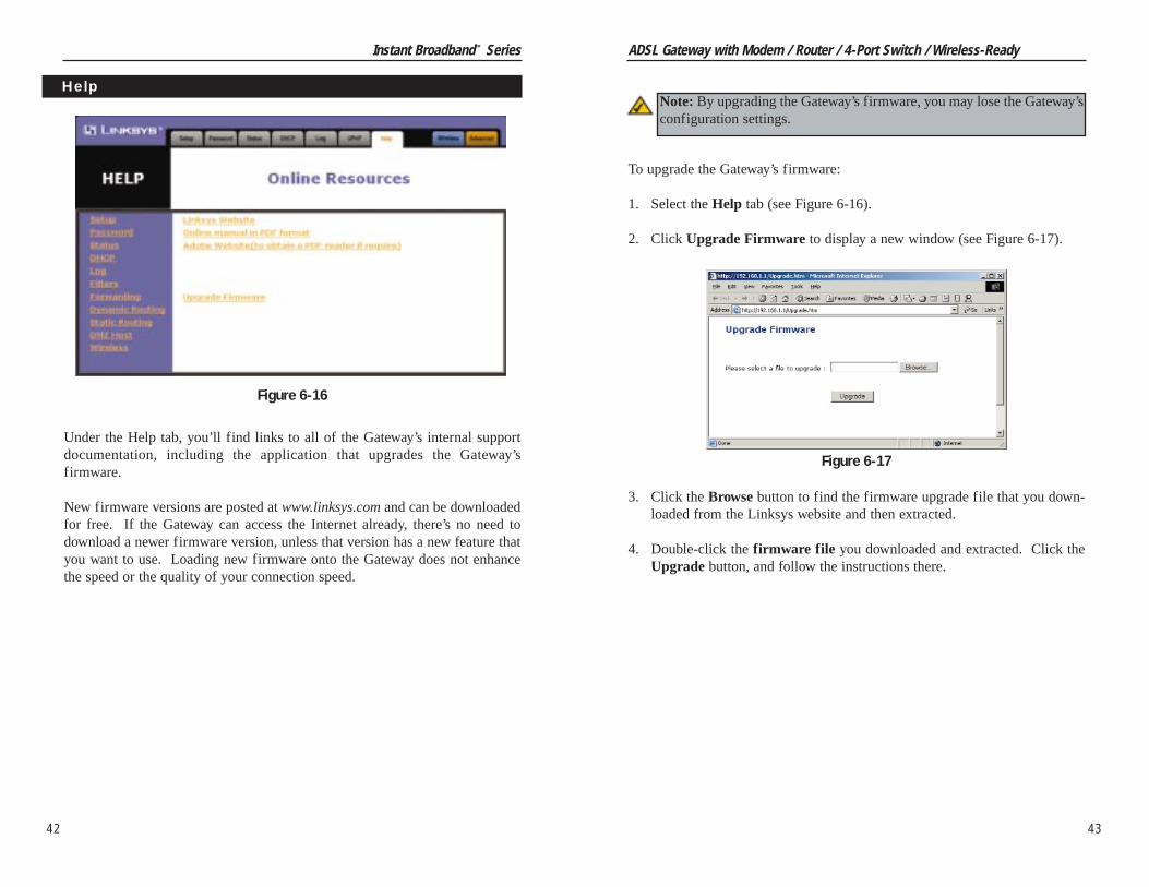
To upgrade the Gateway’s firmware:
1. Select the Help tab (see Figure 6-16).
2. Click Upgrade Firmware to display a new window (see Figure 6-17).
3. Click the Browse button to find the firmware upgrade file that you down-loaded from the Linksys website and then extracted.
4. Double-click the firmware file you downloaded and extracted. Click theUpgrade button, and follow the instructions there.
43
Instant Broadband™ Series
Under the Help tab, you’ll find links to all of the Gateway’s internal supportdocumentation, including the application that upgrades the Gateway’sfirmware.
New firmware versions are posted at www.linksys.com and can be downloadedfor free. If the Gateway can access the Internet already, there’s no need todownload a newer firmware version, unless that version has a new feature thatyou want to use. Loading new firmware onto the Gateway does not enhancethe speed or the quality of your connection speed.
42
Help
Figure 6-16
Figure 6-17
Note: By upgrading the Gateway’s firmware, you may lose the Gateway’sconfiguration settings.
ADSL Gateway with Modem / Router / 4-Port Switch / Wireless-Ready
On the WEP Key Setting screen, you can make the following choices:• Select 64- or 128-bit WEP encryption.• Select Passphrase generation for easy setup of encryption fields.• Configure the manual entry of WEP encryption keys.• Configure the default transmit WEP key.
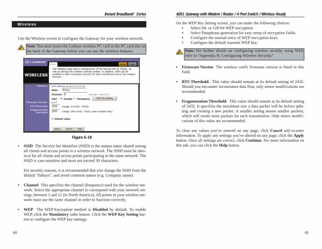
• Firmware Version The wireless card’s firmware version is listed in thisfield.
• RTS Threshold. This value should remain at its default setting of 2432.Should you encounter inconsistent data flow, only minor modifications arerecommended.
• Fragmentation Threshold. This value should remain at its default settingof 2432. It specifies the maximum size a data packet will be before split-ting and creating a new packet. A smaller setting means smaller packets,which will create more packets for each transmission. Only minor modifi-cations of this value are recommended.
To clear any values you’ve entered on any page, click Cancel and re-enterinformation. To apply any settings you’ve altered on any page, click the Applybutton. Once all settings are correct, click Continue. For more information onthis tab, you can click the Help button.
45
Use the Wireless screen to configure the Gateway for your wireless network.
• SSID The Service Set Identifier (SSID) is the unique name shared amongall clients and access points in a wireless network. The SSID must be iden-tical for all clients and access points participating in the same network. TheSSID is case-sensitive and must not exceed 30 characters.
For security reasons, it is recommended that you change the SSID from thedefault “linksys”, and avoid common names (e.g. Company name).
• Channel This specifies the channel (frequency) used for the wireless net-work. Select the appropriate channel to correspond with your network set-tings, between 1 and 11 (in North America). All points in your wireless net-work must use the same channel in order to function correctly.
• WEP The WEP Encryption method is Disabled by default. To enableWEP, click the Mandatory radio button. Click the WEP Key Setting but-ton to configure the WEP key settings.
Figure 6-18
Instant Broadband™ Series
44
Wireless
Note: For further details on configuring wireless security using WEP,refer to “Appendix B: Configuring Wireless Security.”
Note: You must insert the Linksys wireless PC card in the PC card slot onthe back of the Gateway before you can use the wireless features.
Instant Broadband™ Series
46
The following instructions are for advanced users or users whose setup needsrequire special configuration. When you click the Advanced tab, you will beable to set up these features. There are seven additional tabs available.
• Filters - Block specific internal users from Internet access and enable VirtualPrivate Network (VPN) sessions.
• Forwarding - Sets up public services on your network.• Dynamic Routing - Sets up the Gateway so it will automatically adjust to
physical changes in the network’s layout.• Static Routing - Sets up static routes needed when network information must
travel to a specific host or network.• DMZ Host - Allows one local user to be exposed to the Internet for use of
special-purpose services such as online gaming or videoconferencing.• Firewall - Allows the Gateway to use Stateful Packet Inspection (SPI) to auto-
matically detect and block Denial of Service (DoS) and hacking attempts.• Link Test - Allows an advanced user or technician to perform advanced diag-
nostics of the ADSL Gateway and perform connectivity tests.
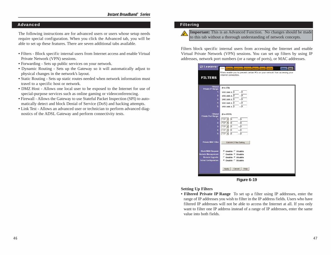
Filters block specific internal users from accessing the Internet and enableVirtual Private Network (VPN) sessions. You can set up filters by using IPaddresses, network port numbers (or a range of ports), or MAC addresses.
Setting Up Filters• Filtered Private IP Range To set up a filter using IP addresses, enter the
range of IP addresses you wish to filter in the IP address fields. Users who havefiltered IP addresses will not be able to access the Internet at all. If you onlywant to filter one IP address instead of a range of IP addresses, enter the samevalue into both fields.
Advanced Filtering
Important: This is an Advanced Function. No changes should be madeto this tab without a thorough understanding of network concepts.
47
Figure 6-19

ADSL Gateway with Modem / Router / 4-Port Switch / Wireless-Ready
49
Instant Broadband™ Series
48
Port Range Forwarding sets up public services on your network, such as webservers, ftp servers, e-mail servers, or other specialized Internet applications.(Specialized Internet applications are any applications that use Internet accessto perform functions such as videoconferencing or online gaming. SomeInternet applications may not require any forwarding.) When users send thistype of request to your network via the Internet, the Gateway will forward thoserequests to the appropriate PC.
You may use this feature to establish a web server or FTP server for Internetusers to access. Be sure that you enter a valid IP address; you may need toestablish a static IP address with your ISP in order to properly run an Internetserver. For added security, Internet users will be able to communicate with theserver, but they will not actually be connected. The packets will be forwardedthrough the Gateway instead. If you need to forward all ports to one PC, see the“DMZ” section.
Forwarding
Important: This is an Advanced Function. No changes should be madeto this tab without a thorough understanding of network concepts.
• Filtered Private Port Range To filter users by network port number, enter anetwork port number or a range of network ports. Select the protocol for eachport number you want to filter, TCP or UDP. Enter the port numbers you wantto filter in the port numbers fields. Users connected to the Gateway will nolonger be able to access any port number listed there.
Private MAC Filter• Click the Edit MAC Filter Setting button to filter users by entering their
physical addresses.
In the MAC Filter Setting screen, enter the MAC addresses that you want tofilter in the MAC address fields. The users with the filtered MAC addresseswill not be able to access the Internet. Click the Apply button and theContinue button, before closing the window.
Block WAN Requests• This feature is designed to protect users from Internet hackers and other
attacks. When enabled, the Gateway will ignore both unknown TCP andICMP packets from the WAN side. By enabling the Block WAN Request fea-ture, you can prevent your network from being “pinged,” or detected, by otherInternet users. The Block WAN Request feature also reinforces your networksecurity by hiding your network ports. Both functions of the Block WANRequest feature make it more difficult for outside users to work their way intoyour network.
Remote Management• This feature allows you to manage or configure the Gateway from a remote
location, via the Internet. To enable management through the WAN connec-tion, click Enable, and use port 8080 on the remote PC you are using forremote management.
Remote Upgrade • This feature allows you to upgrade the Gateway’s firmware from a remote
location. To enable Remote Upgrade, click Enable.
Telnet Configuration• This feature enables or disables telnet access to the Gateway.
To clear any values you’ve entered on any page, click Cancel and re-enterinformation. To apply any settings you’ve altered on any page, click the Applybutton. Once all settings are correct, click Continue. For more information onthis tab, you can click the Help button. Figure 6-20

ADSL Gateway with Modem / Router / 4-Port Switch / Wireless-Ready
51
Instant Broadband™ Series
50
With Dynamic Routing you can enable the Gateway to automatically adjust tophysical changes in the network’s layout. The Gateway, using the RIP protocol,determines the network packets’ route based on the fewest number of hopsbetween the source and the destination. The RIP protocol regularly broadcastsrouting information to other routers on the network. Select the RIP directionsand versions for the LAN and WAN sides.
RIP DirectionDetermines the direction that RIP routes will be updated.
• None RIP is disabled.• Both The Gateway will incorporate received RIP information and send out
updated RIP information.• In Only The Gateway will only incorporate received RIP information.• Out Only The Gateway will only send out RIP information.
Dynamic Routing
Figure 6-21
Important: This is an Advanced Function. No changes should be madeto this tab without a thorough understanding of network concepts.
To add a server using Port Range Forwarding:
1. Enter the name of the application in the appropriate CustomizedApplications field. This field is a description field only.
2. Next to the name of the application, enter the range of the external port(s)used by the server or Internet application in the Ext. Port column. Checkwith the Internet application software documentation for more information.
3. Enter the IP address of the server that you want the Internet users to beable to access. To find the IP address, go to “Appendix D: Finding theMAC Address and IP Address for Your Ethernet Adapter.”
4. Configure as many entries as needed—the Gateway supports up to 11ranges of ports. Click the Apply button and Continue button when you aredone.
To delete a server entry, enter 0 in the Ext. Port and IP Address fields.
To clear any values you’ve entered on any page, click Cancel and re-enterinformation. To apply any settings you’ve altered on any page, click the Applybutton. Once all settings are correct, click Continue. For more information onthis tab, you can click the Help button.

ADSL Gateway with Modem / Router / 4-Port Switch / Wireless-Ready
53
Instant Broadband™ Series
RIP VersionSelect the version of IP you want to use.
• RIP-1 Routing data will be sent in RIPv1 format.• RIP-2B Routing data will be sent in RIPv2 format using subnet broadcast-
ing.• RIP-2M Routing data will be sent in RIPv2 format using multicasting.• N/A Routing data will not be sent.
Click the Show Routing Table button to open a chart displaying how data isrouted through your LAN.
When finished making your changes on this tab, click the Apply button fol-lowed by the Continue button to save these changes, or click the Cancel but-ton to undo your changes. For further help on this tab, click the Help button.
52
If the Gateway is connected to more than one network, it may be necessary toset up a static route between them. A static route is a pre-determined pathwaythat network information must travel to reach a specific host or network. Youcan use static routing to allow different IP domain users to access the Internetthrough the Gateway.
The Gateway is also capable of dynamic routing (see the Dynamic Routingtab). It is usually better to use dynamic routing because it allows the Gatewayto automatically adjust to physical changes in the network’s layout.
To set up static routing, you should add routing entries in the Gateway’s table,so the Gateway knows where to send all incoming packets.
To create a static route entry:
1. Select a Static Route Entry from the drop-down list. The Gateway sup-ports up to eight static route entries.
Static Routing
Figure 6-22
Important: This is an Advanced Function. No changes should be madeto this tab without a thorough understanding of network concepts.

ADSL Gateway with Modem / Router / 4-Port Switch / Wireless-Ready
55
Instant Broadband™ Series
54
The DMZ Hosting function allows for a server attached to Port 4 of theGateway to be fully accessible from the Internet. The Gateway supports anAdvanced form of DMZ, allowing the system attached to Port 4 to be on asecure subnet, separate from the computers attached to the other 3 ports.
Port 4 Status Selecting DMZenables the advanced DMZfunction for the switched Port4. Selecting LAN disables theadvanced DMZ function, andPort 4 acts as a normalswitched port.
DMZ IP Address Enter theIP Address that is assigned tothe Gateway’s Port 4. Enter theSubnet Mask associated with the DMZ network.
Routing This setting is only applicable to the DMZ network.
RIP Direction Determines the direction that RIP routes will be updated.• None RIP is disabled.• Both The Gateway will incorporate received RIP information and send out
updated RIP information.• In Only The Gateway will only incorporate received RIP information.• Out Only The Gateway will only send out RIP information.
RIP Version Select the version of IP you want to use.• RIP-1 Routing data will be sent in RIPv1 format.• RIP-2B Routing data will be sent in RIPv2 format using subnet broad-
casting.• RIP-2M Routing data will be sent in RIPv2 format using multicasting.• N/A Routing data will not be sent.
When finished making your changes on this tab, click the Apply button fol-lowed by the Continue button to save these changes, or click the Cancel but-ton to undo your changes. For further help on this tab, click the Help button.
DMZ Host
Figure 6-23
Important: This is an Advanced Function. No changes should be madeto this tab without a thorough understanding of network concepts.
2. Enter the following data to create a new static route.
Destination LAN IP: The Destination LAN IP is the address of the remotenetwork or host to which you want to assign a static route. Enter the IPaddress of the host for which you wish to create a static route here. For astandard Class C IP domain, the network address is the first three fields ofthe Destination LAN IP, while the last field should be 0.
Subnet Mask: The Subnet Mask (also known as the Network Mask) iden-tifies which portion of an IP address is the network portion, and which por-tion is the host portion. For a full Class C Subnet, the Subnet Mask is255.255.255.0.
Gateway IP: This IP address should be the IP address of the gatewaydevice that allows for contact between the Gateway and the remote networkor host.
Hop Count: This determines the maximum number of steps between net-work nodes that data packets will travel. A node is any device on the net-work, such as PCs, print servers, routers, etc.
From the Static Routing tab, click the Show Routing Table button to view thecurrent static routing configuration.
To delete a Static Routing entry, select an entry, and click the Delete ThisEntry button.
When finished making your changes on this tab, click the Apply button fol-lowed by the Continue button to save these changes, or click the Cancel but-ton to undo your changes. For further help on this tab, click the Help button.
ADSL Gateway with Modem / Router / 4-Port Switch / Wireless-Ready
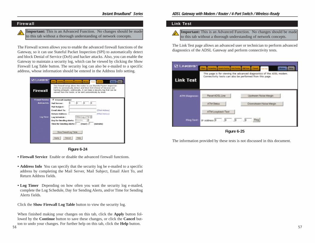
The Link Test page allows an advanced user or technician to perform advanceddiagnostics of the ADSL Gateway and perform connectivity tests.
The information provided by these tests is not discussed in this document.
57
Instant Broadband™ Series
56
Link Test
Figure 6-25
Important: This is an Advanced Function. No changes should be madeto this tab without a thorough understanding of network concepts.
The Firewall screen allows you to enable the advanced firewall functions of theGateway, so it can use Stateful Packet Inspection (SPI) to automatically detectand block Denial of Service (DoS) and hacker attacks. Also, you can enable theGateway to maintain a security log, which can be viewed by clicking the ShowFirewall Log Table button. The security log can also be e-mailed to a specificaddress, whose information should be entered in the Address Info setting.
• Firewall Service Enable or disable the advanced firewall functions.
• Address Info You can specify that the security log be e-mailed to a specificaddress by completing the Mail Server, Mail Subject, Email Alert To, andReturn Address fields.
• Log Timer Depending on how often you want the security log e-mailed,complete the Log Schedule, Day for Sending Alerts, and/or Time for SendingAlerts fields.
Click the Show Firewall Log Table button to view the security log.
When finished making your changes on this tab, click the Apply button fol-lowed by the Continue button to save these changes, or click the Cancel but-ton to undo your changes. For further help on this tab, click the Help button.
Firewall
Figure 6-24
Important: This is an Advanced Function. No changes should be madeto this tab without a thorough understanding of network concepts.

ADSL Gateway with Modem / Router / 4-Port Switch / Wireless-Ready
Make sure that you do NOT have a microfilter plugged in between theGateway and the wall jack. Verify that your ADSL account is active withyour ISP.
5. I can’t browse through the Gateway.• Check if both ends of the network cable and power adapter are properly
connected. Check if the status LEDs on the front panel are functioningproperly.
• If using Windows 95, 98 or Millennium, check the TCP/IP setup on theclient side. Run winipcfg by clicking on the Start button, selecting Run,and typing winipcfg in the Run field. Press Enter. The PC should havean IP address of 192.168.1.xxx (“xxx” is from 2 to 254.). The SubnetMask is 255.255.255.0; the default gateway IP should be the Gateway’s IPAddress, and check that the DNS is correct.
• Check the same setup values in the Gateway’s Status page.
6. When I enter a URL or IP address, I get a time out error.• Check to see if your other PCs work. If they do, verify that your PC’s IP
settings are correct (IP address, Subnet Mask, Default Gateway, andDNS)
• If the PCs are configured correctly, but still not working, check theGateway. Make sure that it is connected and ON. Connect to it and checkits settings. (If you cannot connect to it, check the LAN and power con-nections.)
• If the Gateway is configured correctly, check your Internet connection tosee that it is working correctly.
• Manually configure the TCP/IP with a DNS address provided by your ISP.
7. I can’t obtain an IP address from my ADSL line.• Verify that all of your cabling is properly connected and that all of the
Gateway’s ADSL and Link LEDs are correctly illuminated.• Power down your Gateway for a few seconds. Turn it back on. After the
Gateway goes through its self-test, check to see if you now have an IPaddress.
• Verify that the VPI/VCI and Encapsulation settings are correct in theSetup page of the Web-based Utility. Go to the Setup section of the Web-based Utility chapter for more information.
• If you are configured for PPPoE or PPPoA, verify that the username andpassword are entered correctly in the Setup page of the Web-based Utility.Go to the Setup section of the Web-based Utility chapter for more infor-mation.
59
Instant Broadband™ Series
58
Appendix A: Troubleshooting
This section provides possible solutions to problems regarding the Gateway’sinstallation and operation. If your situation is described here, the problemshould be solved by applying the corresponding solution. If you can’t find ananswer here, check the Linksys website at www.linksys.com.
1. The Gateway is not working.• Verify that the Power cord and other network cables are plugged in.• Check the LAN and WAN LEDs on the Gateway’s front and verify that
they are lit appropriately.• Check the settings on your PC.• Check the Gateway’s settings.
2. I can’t connect to the Gateway.• Verify that the Gateway is properly installed; LAN connections are OK,
and it is powered ON.• Make sure that your PC and the Gateway are on the same network seg-
ment. If you are not sure, initiate the DHCP function, and let the PC getthe IP address automatically.
• Make sure that your PC is using an IP address within the default range of192.168.1.2 to 192.168.1.254 and thus compatible with the Gatewaydefault IP Address of 192.168.1.1
• Also, the Subnet Mask should be set to 255.255.255.0 to match theGateway. For the Gateway, you can check these settings by using ControlPanel-Network to check the Properties for the TCP/IP protocol.
3. The Diag LED stays lit when it shouldn’t.• The Diag LED lights up when the device is first powered up. Meantime,
the system will boot up itself and check for proper operation. After fin-ishing the checking procedure, the LED turns off to show the system isworking fine. If the LED remains lit after this time, the device is notworking properly. Try to re-flash the firmware by assigning a static IPaddress to the computer, and then upgrade the firmware again. If thatdoesn’t help, contact your dealer for further inspection.
4. The ADSL Link LED will not go solid.• Verify that the RJ-11 cable is firmly plugged into the ADSL jack of the
Gateway, with the other end plugged directly into the ADSL wall jack.
Common Problems and Solutions

ADSL Gateway with Modem / Router / 4-Port Switch / Wireless-Ready
61
Instant Broadband™ Series
60
I set up an Unreal Tournament Server, but others on the LAN cannot join. What doI need to do? If you have a dedicated Unreal Tournament server running, youneed to create a static IP for each of the LAN computers and forward ports7777, 7778, 7779, 7780, 7781, and 27900 to the IP address of the server. Youcan also use a port forwarding range of 7777 ~ 27900. If you want to use theUT Server Admin, forward another port (8080 usually works well but is usedfor remote admin. You may have to disable this.), and then in the[UWeb.WebServer] section of the server.ini file, set the ListenPort to 8080 (tomatch the mapped port above) and ServerName to the IP assigned to theGateway from your ISP.
Can multiple gamers on the LAN get on one game server and play simultaneouslywith just one public IP address? It depends on which network game or whatkind of game server you are using. For example, Unreal Tournament supportsmulti-login with one public IP.
How do I get Half-Life: Team Fortress to work with the Gateway? The default clientport for Half-Life is 27005. The computers on your LAN need to have“+clientport 2700x” added to the HL shortcut command line; the x would be6, 7, 8, and on up. This lets multiple computers connect to the same server.One problem: Version 1.0.1.6 won’t let multiple computers with the same CDkey connect at the same time, even if on the same LAN (not a problem with1.0.1.3). As far as hosting games, the HL server does not need to be in theDMZ. Just forward port 27015 to the local IP address of the server computer.
The web page hangs; downloads are corrupt, or nothing but junk characters arebeing displayed on the screen. What do I need to do? Force your Ethernetadapter to 10Mbps or half duplex mode, and turn off the “Auto-negotiate”feature of your Ethernet adapter as a temporary measure. (Please look at theNetwork Control Panel in your Ethernet adapter’s Advanced Properties tab.)Make sure that your proxy setting is disabled in the browser. Check our web-site at www.linksys.com for more information.
If all else fails in the installation, what can I do? Reset the Gateway by holdingdown the reset button until the Diag LED fully turns on and off. Obtain andflash the latest firmware release that is readily available on the Linksys web-site, www.linksys.com.
How will I be notified of new Gateway firmware upgrades? All Linksys firmwareupgrades are posted on the Linksys website at www.linksys.com, where theycan be downloaded for free. The Gateway’s firmware can be upgraded withTFTP programs.
What is the maximum number of IP addresses that the Gateway will support? TheGateway will support up to 253 IP addresses.
Is IPSec Pass-Through supported by the Gateway? Yes, it is a built-in feature thatthe Gateway automatically enables.
Does the Gateway support IPX or AppleTalk? No. TCP/IP is the only protocolstandard for the Internet and has become the global standard for communica-tions. IPX, a NetWare communications protocol used only to route messagesfrom one node to another, and AppleTalk, a communications protocol used onApple and Macintosh networks, can be used for LAN to LAN connections,but those protocols cannot connect from WAN to LAN.
What is Network Address Translation and what is it used for? Network AddressTranslation (NAT) translates multiple IP addresses on the private LAN to onepublic address that is sent out to the Internet. This adds a level of securitysince the address of a PC connected to the private LAN is never transmittedon the Internet. Furthermore, NAT allows the Gateway to be used with lowcost Internet accounts, when only one TCP/IP address is provided by the ISP.The user may have many private addresses behind this single address provid-ed by the ISP.
Does the Gateway support any operating system other than Windows 95, Windows98, Windows 2000, Windows NT, or Windows XP? Yes, but Linksys does not, atthis time, provide technical support for setup, configuration or troubleshoot-ing of any non-Windows operating systems.
Does the Gateway support ICQ send file? Yes, with the following fix: click ICQ menu -> preference -> connections tab->, and check I am behind a fire-wall or proxy. Then set the firewall time-out to 80 seconds in the firewall set-ting. The Internet user can then send a file to a user behind the Gateway.
How do I get Napster to work with the Gateway? Napster is fully compatible withthe Gateway, but you must make sure that, during installation, you select “noidea” when asked about your firewall selection. Set your proxy settings to“No Proxy Server” in your File>Preferences.
Frequently Asked Questions

ADSL Gateway with Modem / Router / 4-Port Switch / Wireless-Ready
What are the Gateway’s advanced features? The Gateway’s advanced featuresinclude Filters, Forwarding, Dynamic Routing, Static Routing, and DMZhost.
Does Linksys provide syslog support? No, Linksys does not currently providesyslog support.
How can I check whether I have static or dynamic IP Addresses? Consult yourISP to confirm the information.
How do I get mIRC to work with the Gateway? Set port forwarding to 113 for thecomputer on which you are using mIRC. If you are experiencing difficultyafter setting the port forwarding, try changing the Direct Client-to-Client(DCC) settings to a range from 1024 to 1030 on the DCC option andForwarding page of the Web-based Setup Utility.
Can I guess my encapsulation type and VPI/VCI? These settings are dependent onyour telephone company, ADSL ISP, service level, and when your line wasinstalled. It is typically not something that can be guessed or found throughtrial and error. It is best to contact your ISP to find these settings.
Will this product work on an SDSL, IDSL or ISDN line? No, those types of lines arenot ADSL technologies. The BEFDSR41W will only work on ADSL linesthat support the T1.413i2, G.992.1 (G.dmt), or G.992.2 (G.lite) standards.
If your questions are not addressed here, refer to the contact informationon the last page of this manual, or online at support.linksys.com.
63
Instant Broadband™ Series
62
Will the Gateway function in a Macintosh environment? Yes, but the Gateway’ssetup pages are accessible only through Internet Explorer v4.0 or NetscapeNavigator v4.0 or higher for Macintosh. NOTE: Linksys does not providetechnical support for Macintosh computers.
With which type of firewall is the Gateway equipped? The Gateway uses NAT andTCP/IP port inspections. It also has SPI (Stateful Packet Inspection).
Does the Gateway do Stateful Packet Inspection? Yes. Enable the Firewall func-tion of the Gateway.
I am not able to access the Gateway’s web configuration screen. What can I do?You may have to remove the proxy settings on your Internet browser, e.g.,Netscape Navigator or Internet Explorer. Or remove the dial-up settings onyour browser. Check with your browser documentation.
What is DMZ? Demilitarized Zone (DMZ) allows one IP address (computer) tobe exposed to the Internet. Some applications require multiple TCP/IP portsto be open. It is recommended that you set your computer with a static IP ifyou want to use DMZ.
If DMZ is used, does the exposed user share the public IP with the Gateway? No.
Does the Gateway pass PPTP packets or actively route PPTP sessions? TheGateway allows PPTP packets to pass through.
Is the Gateway cross-platform compatible? Any platform that supports Ethernetand TCP/IP is compatible with the Gateway.
Will the Gateway allow me to use my own public IPs and Domain, or do I have touse the IPs provided by the Gateway? The Gateway allows for customizationof your public IPs and Domain.
How many ports can be simultaneously forwarded? Theoretically, the Gatewaycan establish 520 sessions at the same time, but you can only forward 10ranges of ports.
Does the Gateway replace a modem? Is there a DSL modem in the Gateway? Yes.The Gateway has an integrated ADSL modem, so this product will replaceyour current ADSL modem.

ADSL Gateway with Modem / Router / 4-Port Switch / Wireless-Ready
65
Instant Broadband™ Series
64
1. At the Wireless Screen, if you choose to enable WEP Encryption, selectMandatory under the WEP section.
2. Press the WEP Key Setting button to set the WEP Encryption type andlevel.
3. The following screen may appear, verifying that you are enabling WEPEncryption. Press the OK button to continue.
Figure B-2
Figure B-1
Appendix B: ConfiguringWireless Security
An acronym for Wired Equivalent Privacy, WEP is an encryption scheme usedto protect your wireless data communications. WEP uses a combination of 64-bit or 128-bit keys to provide access control to your network and encryptionsecurity for every data transmission. To decode a data transmission, each pointin a network must use an identical 64-bit or 128-bit key. Higher encryption lev-els mean higher levels of security, but due to the complexity of the encryption,they may mean decreased network performance.
You may also have heard the term “40-bit” used in conjunction with WEPEncryption. This is simply another term for 64-bit WEP encryption. This levelof WEP encryption has been called 40-bit because it uses a 40-bit secret keyalong with a 24-bit Initialization Vector (40 + 24 = 64). Wireless vendors mayuse either name. Linksys uses the term “64-bit” when referring to this level ofencryption.
If possible, make sure your wireless network is functioning before attemptingto configure WEP.
A 128-bit WEP encrypted wireless network will NOT communicate with a 64-bit WEP encrypted wireless network. Therefore, make sure that all of yourwireless devices are using the same encryption level. All wireless devices com-plying with the 802.11b standard will support 64-bit WEP.
In addition to enabling WEP, Linksys also recommends the following securityimplementations:• Changing the SSID from the default “linksys”• Changing the WEP key regularly
Note: WEP Encryption is an additional data security measure andnot essential for Gateway operation.
Note: In order for WEP Encryption to be enabled, wireless functions must firstbe enabled. Select Enable under the Wireless section before proceeding.

ADSL Gateway with Modem / Router / 4-Port Switch / Wireless-Ready
WEP Encryption key can be generated in one of two ways:
1. You may create an encryption key by using a Passphrase.
a. Enter a Passphrase, a user-defined password, into the Passphrase field.The Passphrase can be a maximum of 31 letters, symbols, and numbers.No spaces can be used.
b. Click the Generate button to create a key. The key will be 10 digits ifyou chose 64-bit encryption, or 26 digits if you chose 128-bit encryp-tion. This key will be used to encrypt and decrypt the data being sentbetween the Gateway and your network’s wireless PCs.
The Key field may not display all digits. Using the mouse, click any-where within the Key field. Move the cursor to the right to view the restof the Key. Make sure your write down the entire Key EXACTLY theway it is displayed.
2. You may enter the encryption key manually.
Make a note of the Passphrase or Manual Key. You will need it for other wire-less devices on the network, as the same WEP encryption key must be enteredin all wireless devices on the network.
Once you have chosen your key encryption method and entered either thePassphrase or manual key, click the Apply button, and the encryption portionof the setup is complete.
67
Instant Broadband™ Series
4. The following screen will appear, where you will choose your WEPEncryption settings.
• WEP (64Bit or 128B) Select the level of encryption from the drop-downbox. 128-bit WEP encryption is unique to Linksys and may conflict withother vendors’ WEP encryption.
66
Note: In Windows XP, a 128-bit Key generated by the Gateway will be called a"104 bits (26 digits)" key, and a 64-bit Key generated by the Gateway will becalled a “40 bits (10 digits)” key.
Figure B-3
Note: In order to utilize WEP encryption, all points in your wireless networkmust have WEP enabled and be set to the same Key Setting.

ADSL Gateway with Modem / Router / 4-Port Switch / Wireless-Ready
2. In the “Control Panel” window, click the Network and InternetConnections icon.
3. Click on the Network Connections icon.
4. The “Network Connections” window will appear. Under LAN or High-Speed Internet you will see all Network cards that are installed and operat-ing in your computer. Double-click the Wireless Network Connectionicon associated with your wireless adapter.
If the “Wireless Network Connection Status” window appears, continue tothe next step.
69
Instant Broadband™ Series
As Windows XP does not allow for the use of the Linksys Passphrase featurewith the wireless PC adapters, you will need to manually enter the key gener-ated in the previous section.
The following steps will help you enable WEP and enter the encryption keymanually for your wireless PC cards, in order to enable your Windows XP sys-tem to communicate with the Gateway wirelessly.
These steps assume that your CD-ROM drive is letter D and that you are run-ning Windows XP in the default mode.
Be sure you have the WEP Key generated by the Gateway.
1. Click the Start button and go to the Control Panel.
68
Figure B-5
Figure B-6
Configuring Wireless Security in Windows XP
Figure B-4
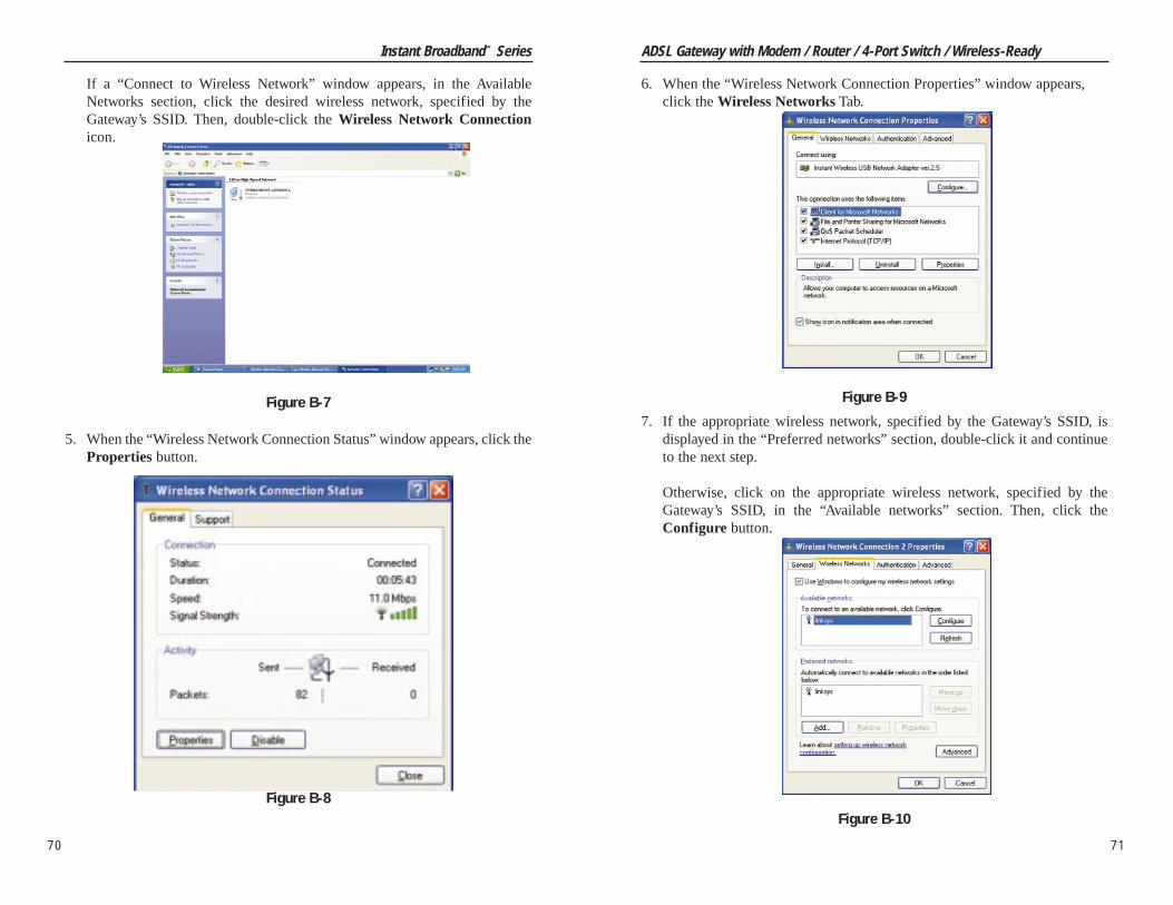
ADSL Gateway with Modem / Router / 4-Port Switch / Wireless-Ready
71
Instant Broadband™ Series
70
6. When the “Wireless Network Connection Properties” window appears,click the Wireless Networks Tab.
7. If the appropriate wireless network, specified by the Gateway’s SSID, isdisplayed in the “Preferred networks” section, double-click it and continueto the next step.
Otherwise, click on the appropriate wireless network, specified by theGateway’s SSID, in the “Available networks” section. Then, click theConfigure button.
Figure B-9
Figure B-10
If a “Connect to Wireless Network” window appears, in the AvailableNetworks section, click the desired wireless network, specified by theGateway’s SSID. Then, double-click the Wireless Network Connectionicon.
5. When the “Wireless Network Connection Status” window appears, click theProperties button.
Figure B-7
Figure B-8

ADSL Gateway with Modem / Router / 4-Port Switch / Wireless-Ready
Appendix C: Installing theTCP/ I P ProtocolFollow these instructions to install the TCP/IP protocol on one of your PCs onlyafter a network card has been successfully installed inside the PC. Theseinstructions are for Windows 95, Windows 98, and Windows Me. For TCP/IPsetup under Windows NT, 2000, and XP, see your Windows manual.
1. Click the Start button. Choose Settings and then Control Panel.
2. Double-click on the Network icon to bring up your Network window.Select the Configuration tab.
3. Click the Add button.
4. Double-click on Protocol.
5. Highlight Microsoft under the list of manufacturers.
73
Instant Broadband™ Series
72
Figure C-1
8. The “Wireless Network Properties” window will appear.
Click the check box for the Data encryption (WEP enabled) option.
Remove the check from the Network Authentication (Shared mode) andThe key is provided for me automatically fields.
In the "Network key" field, enter the exact Key (all 10 or 26 digits, depend-ing on the level of encryption) generated by the Gateway.
Verify that the “Key format” field displays “Hexadecimal digits” and thatthe “Key length” field displays either “40 bits (10 digits)” or “104 bits (26digits)”. If this is not displayed, you have entered the key incorrectly.
Click the OK button to save the settings. Click on OK buttons until youget back to the “Wireless Network Connection Status” window. Close anyopen windows to get back to the Windows XP desktop.
Close any applications and reboot your PC. After reboot, WEP configurationis complete and you should be able to connect wirelessly to the Gateway.
Figure B-11

ADSL Gateway with Modem / Router / 4-Port Switch / Wireless-Ready
Appendix D: Finding the MACAddress and IP Address for YourEthernet AdapterThis section describes how to find the MAC address for your Ethernet adapterto do either MAC Filtering for the Gateway and ISP. You can also find the IPaddress of your computer’s Ethernet adapter. The IP address is used for filter-ing. Follow the steps in this appendix to find the MAC address or IP addressfor your adapter in Windows 95, 98, Me, NT, 2000, and XP.
For Windows 95, 98, and Me:
1. Click on Start and Run. In the Open field, enter winipcfg. Then press theEnter key or the OK button.
2. When the IP Configuration window appears, select the Ethernet adapteryou are using to connect to the Gateway via a CAT 5 Ethernet cable.
75
Instant Broadband™ Series
6. Find and double-click TCP/IP in the list to the right (see Figure C-2).
7. After a few seconds, the main Network window will appear. The TCP/IPProtocol should now be listed.
8. Click the OK button. Windows may ask for original Windows installationfiles. Supply them as needed, e.g., c:\windows\options\cabs, D:\win98,D:\win95.
9. Windows will ask you to restart the PC. Click the Yes button.
The TCP/IP installation is now complete.
74
Figure D-1
Figure D-2
Figure C-2
Figure C-3

ADSL Gateway with Modem / Router / 4-Port Switch / Wireless-Ready
2. In the command prompt, enter ipconfig /all. Then press the Enter key.
3. Write down the Physical Address as shown on your computer screen; it isthe MAC address for your Ethernet adapter. This will appear as a series ofletters and numbers.
The MAC address/Physical Address is what you will use for MACFiltering.
The example in Figure D-5 shows the IP address of your Ethernet adapteras 192.168.1.100. Your computer may show something different.
77
Instant Broadband™ Series
3. Write down the Adapter Address as shown on your computer screen (seeFigure D-3). This is the MAC address for your Ethernet adapter and willbe shown as a series of numbers and letters.
The MAC address/Adapter Address is what you will use for MACFiltering.
The example in Figure D-3 shows the IP address of your Ethernet adapteras 192.168.1.100. Your computer may show something different.
For Windows NT, 2000, and XP:
The following steps show an alternative way of obtaining the MAC address andIP address for your Ethernet adapter.
1. Click on Start and Run. In the Open field, enter cmd. Press the Enter keyor click the OK button.
76
Figure D-5
Note: The MAC address is also called the PhysicalAddress.
Figure D-3
Figure D-4
Note: The MAC address is also called the AdapterAddress.
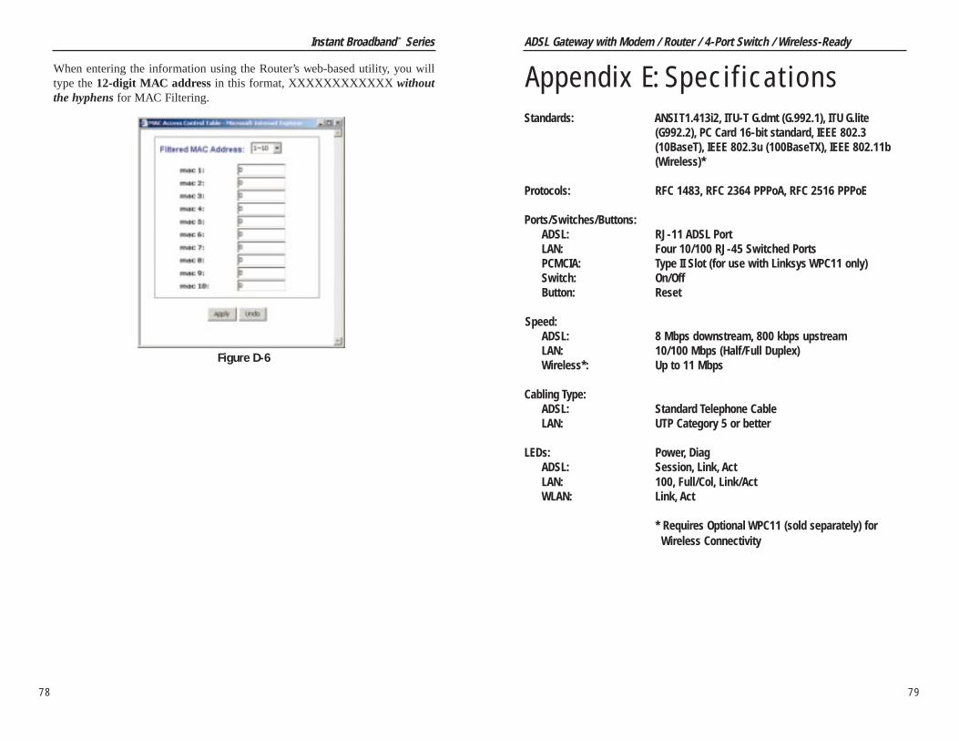
ADSL Gateway with Modem / Router / 4-Port Switch / Wireless-Ready
79
Instant Broadband™ Series
When entering the information using the Router’s web-based utility, you willtype the 12-digit MAC address in this format, XXXXXXXXXXXX withoutthe hyphens for MAC Filtering.
78
Appendix E: SpecificationsStandards: ANSI T1.413i2, ITU-T G.dmt (G.992.1), ITU G.lite
(G992.2), PC Card 16-bit standard, IEEE 802.3(10BaseT), IEEE 802.3u (100BaseTX), IEEE 802.11b(Wireless)*
Protocols: RFC 1483, RFC 2364 PPPoA, RFC 2516 PPPoE
Ports/Switches/Buttons:ADSL: RJ-11 ADSL PortLAN: Four 10/100 RJ-45 Switched PortsPCMCIA: Type II Slot (for use with Linksys WPC11 only)Switch: On/OffButton: Reset
Speed:ADSL: 8 Mbps downstream, 800 kbps upstreamLAN: 10/100 Mbps (Half/Full Duplex)Wireless*: Up to 11 Mbps
Cabling Type:ADSL: Standard Telephone CableLAN: UTP Category 5 or better
LEDs: Power, DiagADSL: Session, Link, ActLAN: 100, Full/Col, Link/ActWLAN: Link, Act
* Requires Optional WPC11 (sold separately) for Wireless Connectivity
Figure D-6

ADSL Gateway with Modem / Router / 4-Port Switch / Wireless-Ready
Appendix F: Warranty InformationBE SURE TO HAVE YOUR PROOF OF PURCHASE AND A BARCODEFROM THE PRODUCT’S PACKAGING ON HAND WHEN CALLING.RETURN REQUESTS CANNOT BE PROCESSED WITHOUT PROOF OFPURCHASE.
IN NO EVENT SHALL LINKSYS’S LIABILITY EXCEED THE PRICEPAID FOR THE PRODUCT FROM DIRECT, INDIRECT, SPECIAL, INCI-DENTAL, OR CONSEQUENTIAL DAMAGES RESULTING FROM THEUSE OF THE PRODUCT, ITS ACCOMPANYING SOFTWARE, OR ITSDOCUMENTATION. LINKSYS DOES NOT OFFER REFUNDS FOR ANYPRODUCT.
LINKSYS OFFERS CROSS SHIPMENTS, A FASTER PROCESS FOR PRO-CESSING AND RECEIVING YOUR REPLACEMENT. LINKSYS PAYSFOR UPS GROUND ONLY. ALL CUSTOMERS LOCATED OUTSIDE OFTHE UNITED STATES OF AMERICA AND CANADA SHALL BE HELDRESPONSIBLE FOR SHIPPING AND HANDLING CHARGES. PLEASECALL LINKSYS FOR MORE DETAILS.
81
Instant Broadband™ Series
Dimensions: 7.32" x 6.06" x 2.52" (186 mm x 154 mm x 62 mm)
Unit Weight: 14.4 oz. (0.40 kg)
Power: External, 12V AC, 1.25 A
Certifications: FCC Class B, Part 68, CE Mark
Operating Temp.: 0ºC to 40ºC (32ºF to 104ºF)
Storage Temp.: 0ºC to 60ºC (32ºF to 140ºF)
Operating Humidity: 10% to 85%, Non-Condensing
Storage Humidity: 10% to 90%, Non-Condensing
80
Environmental

© Copyright 2002 Linksys, All Rights Reserved.
www.linksys.com
Appendix G: Contact InformationFor help with the installation or operation of your ADSL Gateway with Modem/ Router / 4-Port Switch / Wireless-Ready, contact Linksys Technical Supportat one of the phone numbers or Internet addresses below.
Sales Information 800-546-5797 (1-800-LINKSYS)Technical Support 800-326-7114 (toll free from U.S. or Canada)
949-271-5465 (6:00 am to 5:00 pm PST)RMA Issues 949-271-5461Fax 949-265-6655Email [email protected] site http://www.linksys.com
http://support.linksys.comFTP site ftp://ftp.linksys.com
8382
Instant Broadband™ Series ADSL Gateway with Modem / Router / 4-Port Switch / Wireless-Ready