ModelSim Command Reference - Support Serverfwinkler/psvfpga/synthese/... · ModelSim Command...
210
ModelSim® Xilinx Command Reference Version 5.5e Published: 25/Sep/01 The world’s most popular HDL simulator
Transcript of ModelSim Command Reference - Support Serverfwinkler/psvfpga/synthese/... · ModelSim Command...
ModelSim®
Xilinx
Command ReferenceV e r s i o n 5 . 5 e
P u b l i s h e d : 2 5 / S e p / 0 1
T h e w o r l d ’ s m o s t p o p u l a r H D L s i m u l a t o r

ii
Mod
ModelSim is produced by Model Technology™ Incorporated. Unauthorized copying, duplication, or other reproduction is prohibited without the written consent of Model Technology.
The information in this manual is subject to change without notice and does not represent a commitment on the part of Model Technology. The program described in this manual is furnished under a license agreement and may not be used or copied except in accordance with the terms of the agreement. The online documentation provided with this product may be printed by the end-user. The number of copies that may be printed is limited to the number of licenses purchased.
ModelSim is a registered trademark of Model Technology Incorporated. Model Technology is a trademark of Mentor Graphics Corporation. PostScript is a registered trademark of Adobe Systems Incorporated. UNIX is a registered trademark of AT&T in the USA and other countries. FLEXlm is a trademark of Globetrotter Software, Inc. IBM, AT, and PC are registered trademarks, AIX and RISC System/6000 are trademarks of International Business Machines Corporation. Windows, Microsoft, and MS-DOS are registered trademarks of Microsoft Corporation. OSF/Motif is a trademark of the Open Software Foundation, Inc. in the USA and other countries. SPARC is a registered trademark and SPARCstation is a trademark of SPARC International, Inc. Sun Microsystems is a registered trademark, and Sun, SunOS and OpenWindows are trademarks of Sun Microsystems, Inc. All other trademarks and registered trademarks are the properties of their respective holders.
Copyright (c) 1990 -2001, Model Technology Incorporated.All rights reserved. Confidential. Online documentation may be printed by licensed customers of Model Technology Incorporated for internal business purposes only.
ModelSim support
Support for ModelSim is available from your FPGA vendor. See the About ModelSim dialog box (accessed via the Help menu) for contact information.
elSim Command Reference

CR-3
Table of Contents
Syntax and conventions (CR-5)
Documentation conventions CR-6
Command return values CR-7
Command shortcuts CR-7
Command history shortcuts CR-7
Numbering conventions CR-8
File and directory pathnames CR-9
HDL item pathnames CR-10
Wildcard characters CR-13
ModelSim variables CR-14
Simulation time units CR-14
Comments in argument files CR-14
GUI_expression_format CR-16
Commands (CR-25)
Command reference table CR-26
abort CR-31
add list CR-32
add wave CR-35
alias CR-39
batch_mode CR-40
bd CR-41
bookmark add wave CR-42
bookmark delete wave CR-43
bookmark goto wave CR-44
bookmark list wave CR-45
bp CR-46
cd CR-49
change CR-50
configure CR-51
dataset alias CR-54
dataset clear CR-55
dataset close CR-56
dataset info CR-57
dataset list CR-58
dataset open CR-59
dataset rename CR-60
delete CR-61
describe CR-62
disablebp CR-63
do CR-64
drivers CR-65
dumplog64 CR-66
echo CR-67
edit CR-68
enablebp CR-69
environment CR-70
examine CR-71
exit CR-73
find CR-74
force CR-76
help CR-79
history CR-80
log CR-81
lshift CR-83
lsublist CR-84
modelsim CR-85
noforce CR-86
nolog CR-87
notepad CR-89
noview CR-90
nowhen CR-91
onbreak CR-92
onElabError CR-93
onerror CR-94
pause CR-95
project CR-96
pwd CR-98
quietly CR-99
quit CR-100
radix CR-101
report CR-102
restart CR-104
ModelSim Command Reference

CR-4 Table of Contents
Model
resume CR-106
run CR-107
searchlog CR-109
shift CR-111
show CR-112
status CR-113
step CR-114
stop CR-115
tb CR-116
transcript CR-117
tssi2mti CR-118
vcd add CR-119
vcd checkpoint CR-120
vcd comment CR-121
vcd file CR-122
vcd files CR-123
vcd flush CR-124
vcd limit CR-125
vcd off CR-126
vcd on CR-127
vcd2wlf CR-128
vcom CR-129
vdel CR-134
vdir CR-135
vgencomp CR-136
view CR-138
virtual count CR-139
virtual define CR-140
virtual delete CR-141
virtual describe CR-142
virtual expand CR-143
virtual function CR-144
virtual hide CR-147
virtual log CR-148
virtual nohide CR-150
virtual nolog CR-151
virtual region CR-153
virtual save CR-154
virtual show CR-155
virtual signal CR-156
virtual type CR-159
vlib CR-161
vlog CR-162
vmake CR-166
vmap CR-167
vsim CR-168
vsim<info> CR-179
vsource CR-180
when CR-181
where CR-185
wlf2log CR-186
write format CR-188
write list CR-190
write preferences CR-191
write report CR-192
write transcript CR-193
write tssi CR-194
write wave CR-196
Index (CR-199)
Sim Command Reference

CR-5
Syntax and conventions
Chapter contentsDocumentation conventions . . . . . . . . . . . . CR-6
Command return values . . . . . . . . . . . . . CR-7
Command shortcuts . . . . . . . . . . . . . . CR-7
Command history shortcuts . . . . . . . . . . . . CR-7
Numbering conventions . . . . . . . . . . . . . CR-8
File and directory pathnames . . . . . . . . . . . . CR-9
HDL item pathnames . . . . . . . . . . . . . . CR-10
Wildcard characters . . . . . . . . . . . . . . CR-13
ModelSim variables . . . . . . . . . . . . . . CR-14
Simulation time units . . . . . . . . . . . . . . CR-14
Comments in argument files . . . . . . . . . . . . CR-14
GUI_expression_format . . . . . . . . . . . . . CR-16
ModelSim Command Reference

CR-6 Syntax and conventions
Model
Documentation conventions
This manual uses the following conventions to define ModelSim command syntax
Syntax notation Description
< > angled brackets surrounding a syntax item indicate a user-defined argument; do not enter the brackets in commands
[ ] square brackets generally indicate an optional item; if the brackets surround several words, all must be entered as a group; the brackets are not entereda
a.One exception to this rule is when you are using Verilog syntax to designate an arrayslice. For example,
add wave {vector1[4:0]}
The square brackets in this case denote an index. The braces prevents the Tcl interpreterfrom treating the text within the square brackets as a Tcl command.
{ } braces indicate that the enclosed expression contains one or more spaces yet should be treated as a single argument, or that the expression contains square brackets for an index; for either situation, the braces are entered
... an ellipsis indicates items that may appear more than once; the ellipsis itself does not appear in commands
| the vertical bar indicates a choice between items on either side of it; do not include the bar in the command
monospaced type monospaced type is used in command examples
#--
comments included with commands are preceded by the number sign (#) or by two hyphens (--); useful for adding comments to DO files (macros)
Note: Neither the prompt at the beginning of a line nor the <Enter> key that ends a line is shown in the command examples.
Sim Command Reference

Command return values CR-7
Command return values
All simulator commands are invoked using Tcl. For most commands that write information to the Main window, that information is also available as a Tcl result. By using command substitution the results can be made available to another command or assigned to a Tcl variable. For example:
set aluinputs [find -in alu/*]
sets variable "aluinputs" to the result of the find command (CR-74).
Command shortcuts
You may abbreviate command syntax, but there’s a catch — the minimum characters required to execute a command are those that make it unique. Remember, as we add new commands some of the old shortcuts may not work.
Command history shortcuts
The simulator command history may be reviewed, or commands may be reused, with these shortcuts at the ModelSim/VSIM prompt:
Shortcut Description
up and down arrows scrolls through the command history with the keyboard arrows
click on prompt left-click once on a previous ModelSim or VSIM prompt in the transcript to copy the command typed at that prompt to the active cursor
history shows the last few commands (up to 50 are kept)
ModelSim Command Reference

CR-8 Syntax and conventions
Model
Numbering conventions
Numbers in ModelSim can be expressed in either VHDL or Verilog style. Two styles can be used for VHDL numbers, one for Verilog.
VHDL numbering conventions
The first of two VHDL number styles is:
[ - ] [ radix # ] value [ # ]
Examples
16#FFca23#2#11111110-23749
The second VHDL number style is:
base "value"
Examples
B"11111110"X"FFca23"
Element Description
- indicates a negative number; optional
radix can be any base in the range 2 through 16 (2, 8, 10, or 16); by default, numbers are assumed to be decimal; optional
value specifies the numeric value, expressed in the specified radix; required
# is a delimiter between the radix and the value; the first # sign is required if a radix is used, the second is always optional
Note: A ‘-’ can also be used to designate a "don’t care" element when you search for a signal in the List or Wave window. If you want the ‘-’ to be read as a "don’t care" element, rather than a negative sign, be sure to enclose the number in double quotes. For instance, you would type "-0110--" as opposed to -0110--. If you don’t include the double quotes, ModelSim will read the ‘-’ as a negative sign.
Element Description
base specifies the base; binary: B, octal: O, hex: X; required
value specifies digits in the appropriate base with optional underscore separators; default is decimal; required
Sim Command Reference

File and directory pathnames CR-9
Verilog numbering conventions
Verilog numbers are expressed in the style:
[ - ] [ size ] [ base ] value
Examples
‘b11111110 8‘b11111110‘Hffca23 21‘H1fca23-23749
File and directory pathnames
Several ModelSim commands have arguments that point to files or directories. For example, the -y argument to vlog specifies the Verilog source library directory to search for undefined modules. Spaces in file pathnames must be escaped or the entire path must be enclosed in quotes. For example:
vlog top.v -y C:/Documents\ and\ Settings/mcarnes/simprims
or
vlog top.v -y "C:/Documents and Settings/mcarnes/simprims"
Element Description
- indicates a negative number; optional
size the number of bits in the number; optional
base specifies the base; binary: ‘b or ‘B, octal: ‘o or ‘O, decimal: ‘d or ‘D, hex: ‘h or ‘H; optional
value specifies digits in the appropriate base with optional underscore separators; default is decimal, required
Note: A ‘-’ can also be used to designate a "don’t care" element when you search for a signal in the List or Wave windows. If you want the ‘-’ to be read as a "don’t care" element, rather than a negative sign, be sure to enclose the number in double quotes. For instance, you would type "-0110--" as opposed to 7'b-0110--. If you don’t include the double quotes, ModelSim will read the ‘-’ as a negative sign.
ModelSim Command Reference

CR-10 Syntax and conventions
Model
HDL item pathnames
VHDL and Verilog items are organized hierarchically. Each of the following HDL items creates a new level in the hierarchy:
• VHDLcomponent instantiation statement, block statement, and package
• Verilogmodule instantiation, named fork, named begin, task and function
Each level in the hierarchy is also known as a "region."
Multiple levels in a pathname
Multiple levels in a pathname are separated by the character specified in the PathSeparator variable. The default is "/", but it can be set to any single character, such as "." for Verilog naming conventions, or ":" for VHDL IEEE 1076-1993 naming conventions. See the PathSeparator (UM-282) variable for more information.
Absolute pathnames
Absolute pathnames begin with the path separator character. The first name in the path should be the name of a top-level entity or module, but if you leave it off then the first top-level entity or module will be assumed. VHDL designs only have one top-level, so it doesn't matter if it is included in the pathname. For example, if you are referring to the signal CLK in the top-level entity named top, then both of the following pathnames are correct:
/top/clk /clk
Relative pathnames
Relative pathnames do not start with the path separator, and are relative to the current environment. The current environment defaults to the first top-level entity or module and may be changed by the environment command or by clicking on hierarchy levels in the structure window. Each new level in the pathname is first searched downwards relative to the current environment, but if not found is then searched for upwards (same search rules used in Verilog hierarchical names).
Environment variables and pathnames
You can substitute environment variables for pathnames in any argument that requires a pathname. For example:
vlog -v $lib_path/und1
Assuming you have defined $lib_path on your system, vlog will locate the source library file und1 and search it for undefined modules. See "Environment variables" (UM-275) for more information.
Note: Since Verilog designs may contain multiple top-level modules, a path name may be ambiguous if you leave off the top-level module name.
Sim Command Reference

HDL item pathnames CR-11
Indexing signals, memories, and nets
VHDL array signals, and Verilog memories and vector nets can be sliced or indexed. Indexes must be numeric, since the simulator does not know the actual index types. Slice ranges may be represented in either VHDL or Verilog syntax, irrespective of the setting of the PathSeparator (UM-282).
Name case sensitivity
Name case sensitivity is different for VHDL and Verilog. VHDL names are not case sensitive except for extended identifiers in VHDL 1076-1993. In contrast, all Verilog names are case sensitive.
Names in ModelSim commands are case sensitive when matched against case sensitive identifiers, otherwise they are not case sensitive.
Extended identifiers
The following are supported formats for extended identifiers for any command that takes an identifier.
{\ext ident!\ } # Note trailing space.
\\ext\ ident\!\\ # All non-alpha characters escaped
You can specify that backslashes are used for extended identifiers; however, then you can use only forward slashes when you need pathname delimiters. To do this, "uncomment" the following line in the modelsim.ini file and set its value to zero.
BackslashesArePathnameDelimiters = 0
This will allow command lines that can reference signals, variables, and design unit names that use extended identifiers; for example:
examine \clock 2x\
Naming fields in VHDL signals
Fields in VHDL record signals can be specified using the form:
signal_name.field_name
ModelSim Command Reference

CR-12 Syntax and conventions
Model
Example pathnames
Syntax Description
clk specifies the item clk in the current environment
/top/clk specifies the item clk in the top-level design unit.
/top/block1/u2/clk specifies the item clk, two levels down from the top-level design unit
block1/u2/clk specifies the item clk, two levels down from the current environment
array_sig(4) specifies an index of an array item
{array_sig(1 to 10)} specifies a slice of an array item in VHDL syntax
{mysignal[31:0]} specifies a slice of an array item in Verilog syntax
record_sig.field specifies a field of a record
Sim Command Reference

Wildcard characters CR-13
Wildcard characters
Wildcard characters can be used in HDL item names in some simulator commands. Conventions for wildcards are as follows:
You can use square brackets [ ] in wildcard specifications if you place the entire name in curly braces { }:
Examples
*
Matches all items.
{*[0-9]}
Matches all items ending in a digit.
{?in*[0-9]}
Matches such item names as pin1, fin9, and binary2.
Syntax Description
* matches any sequence of characters
? matches any single character
Syntax Description
{[abcd]} matches any character in the specified set
{[a-d]} matches any character in the specified range
{[^a-d]} matches any character not in the set
ModelSim Command Reference

CR-14 Syntax and conventions
Model
ModelSim variables
Several variables are available to control simulation, provide simulator state feedback, or modify the appearance of the ModelSim GUI. To take effect, some variables, such as environment variables, must be set prior to simulation.
ModelSim variables can be referenced in simulator commands by preceding the name of the variable with the dollar sign ($) character. ModelSim uses global Tcl variables for simulator state variables, simulator control variables, simulator preference variables and user-defined variables. Note that case is significant in variable names.
See Appendix A - ModelSim Variables in the User’s Manual for a complete listing of ModelSim variables.
Variable settings report
The report command (CR-102) returns a list of current settings for either the simulator state, or simulator control variables.
Simulation time units
You can specify the time unit for delays in all simulator commands that have time arguments:
force clk 1 50 ns, 1 100 ns -repeat 1 usrun 2 ms
Note that all the time units in a ModelSim command need not be the same.
Unless you specify otherwise as in the examples above, simulation time is always expressed using the resolution units that are specified by the UserTimeUnit variable. See UserTimeUnit (UM-282).
By default, the specified time units are assumed to be relative to the current time unless the value is preceded by the character @, which signifies an absolute time specification.
Comments in argument filesArgument files may be loaded with the -f <filename> argument of the vcom, vlog, and vsim commands. The -f <filename> argument specifies a file that contains more command line arguments.
Comments within the argument files follow these rules:
• All text in a line beginning with // to its end is treated as a comment.
• All text bracketed by /* ... */ is treated as a comment.
Also, program arguments can be placed on separate lines in the argument file, with the newline characters treated as space characters. There is no need to put '\' at the end of each line.
Sim Command Reference

Comments in argument files CR-15
DOS pathnames require a backslash (\), but ModelSim will accept either a backslash or the forward slash (/).
You can change this behavior so that backslashes on comment lines are used for extended identifiers, but then you can only use forward slashes when you need pathname delimiters. To do this, "uncomment" the following line in the modelsim.ini file and set its value to zero.
BackslashesArePathnameDelimiters = 0
This will allow command lines that can reference signals, variables, and design unit names that use extended identifiers; for example:
examine \clock 2x\
Note: VHDL93 uses backslashes to denote extended identifiers. By default ModelSim PE/PLUS uses backslashes as pathname separators. Therefore it cannot recognize extended identifiers.
ModelSim Command Reference

CR-16 Syntax and conventions
Model
GUI_expression_format
The GUI_expression_format is an option of several simulator commands that operate within ModelSim’s GUI environment. The commands that use the expression format are:
configure (CR-51), examine (CR-71), searchlog (CR-109), virtual function (CR-144), and virtual signal (CR-156)
Expression typing
GUI expressions are typed. The supported types consist of six scalar types and two array types.
Scalar types
The scalar types are as follows: boolean, integer, real, time (64-bit integer), enumeration, and signal state. Signal states are represented by the nine VHDL std_logic states: ’U’ ’X’ ’0’ ’1’ ’Z’ ’H’ ’L’ ’W’ and ’-’. Verilog states 0 1 x and z are mapped into these states and the verilog strengths are ignored. Conversion is done automatically when referencing Verilog nets or registers.
Array types
The array types supported are signed and unsigned arrays of signal states. This would correspond to the VHDL std_logic_array type. Verilog registers are automatically converted to these array types. The array type can be treated as either UNSIGNED or SIGNED, as in the IEEE std_logic_arith package. Normally, referencing a signal array causes it to be treated as UNSIGNED by the expression evaluator; to cause it to be treated as SIGNED, use casting as described below. Numeric operations supported on arrays are performed by the expression evaluator via ModelSim’s built-in numeric_standard (and similar) package routines. The expression evaluator selects the appropriate numeric routine based on SIGNED or UNSIGNED properties of the array arguments and the result.
The enumeration types supported are any VHDL enumerated type. Enumeration literals may be used in the expression as long as some variable of that enumeration type is referenced in the expression. This is useful for sub-expressions of the form:
(/memory/state == reading)
Sim Command Reference

GUI_expression_format CR-17
Signal and subelement naming conventions
ModelSim supports naming conventions for VHDL and Verilog signal pathnames, VHDL array indexing, Verilog bit selection, VHDL subrange specification, and Verilog part selection.
Examples in Verilog and VHDL syntax:
top.chip.vlogsig /top/chip/vhdlsigvlogsig[3]vhdlsig(9)vlogsig[5:2]vhdlsig(5 downto 2)
Concatenation of signals or subelements
Elements in the concatenation that are arrays are expanded so that each element in the array becomes a top-level element of the concatenation. But for elements in the concatenation that are records, the entire record becomes one top-level element in the result. To specify that the records be broken down so that their subelements become top-level elements in the concatenation, use the "concat_flatten" directive. Currently we do not support leaving full arrays as elements in the result. (Please let us know if you need that option.)
If the elements being concatenated are of incompatible base type, a VHDL-style record will be created. The record object can be expanded in the Signals and Wave windows just like an array of compatible type elements.
Concatenation syntax for VHDL
<signalOrSliceName1> & <signalOrSliceName2> & ...
Note that the concatenation syntax (below) begins with "&{" rather than just "{". Repetition multipliers are supported, as illustrated in the second line. The repetition element itself may be an arbitrary concatenation subexpression.
Concatenation syntax for Verilog
&{<signalOrSliceName1>, <signalOrSliceName2>, ... }&{<count>{<signalOrSliceName1>}, <signalOrSliceName2>, ... }
Concatenation directives
The concatenation directive (as illustrated below) can be used to constrain the resulting array range of a concatenation or influence how compound objects are treated. By default, the concatenation will be created with descending index range from (n-1) downto 0, where n is the number of elements in the array. The "concat_range" directive completely specifies the index range. The "concat_ascending" directive specifies that the index start at zero and increment upwards. The "concat_flatten" directive flattens the signal structure hierarchy. The "concat_sort_wild_ascending" directive gathers signals by name in ascending order (the default is descending).
(concat_range 31:0)<concatenationExpr> # Verilog syntax(concat_range (31:0))<concatenationExpr> # Also Verilog syntax(concat_range (31 downto 0))<concatenationExpr> # VHDL syntax(concat_ascending) <concatenationExpr>(concat_flatten) <concatenationExpr> # no hierarchy(concat_sort_wild_ascending) <concatenationExpr>
ModelSim Command Reference

CR-18 Syntax and conventions
Model
Examples
&{ "mybusbasename*" }
Gathers all signals in the current context whose names begin with "mybusbasename", sorts those names in descending order, and creates a bus with index range (n-1) downto 0, where n is the number of matching signals found. (Note that it currently does not derive the index name from the tail of the one-bit signal name.)
(concat_range 13:4)&{ "mybusbasename*" }
Specifies the index range to be 13 downto 4, with the signals gathered by name in descending order.
(concat_ascending)&{ "mybusbasename*" }
Specifies an ascending range of 0 to n-1, with the signals gathered by name in descending order.
(concat_ascending)((concat_sort_wild_ascending)&{"mybusbasename*" })
Specifies an ascending range of 0 to n-1, with the signals gathered by name in ascending order.
VHDL record field support
Arbitrarily-nested arrays and records are supported, but operators will only operate on one field at a time. That is, the expression {a == b} where a and b are records with multiple fields, is not supported. This would have to be expressed as:
{(a.f1 == b.f1) && (a.f2 == b.f2)...}
Examples:
vhdlsig.field1vhdlsig.field1.subfield1vhdlsig.(5).field3vhdlsig.field4(3 downto 0)
Grouping and precedence
Operator precedence generally follows that of the C language, but we recommend liberal use of parentheses.
Sim Command Reference

GUI_expression_format CR-19
Expression syntax
GUI expressions generally follow C-language syntax, with both VHDL-specific and Verilog-specific conventions supported. These expressions are not parsed by the Tcl parser, and so do not support general Tcl; parentheses should be used rather than curly braces. Procedure calls are not supported.
A GUI expression can include the following elements: Tcl macros, constants, array constants, variables, array variables, signal attributes, operators and casting.
Tcl macros
Macros are useful for pre-defined constants or for entire expressions that have been previously saved. The substitution is done only once, when the expression is first parsed. Macro syntax is:
$<name>
Substitutes the string value of the Tcl global variable <name>.
Constants
Type Values
boolean value 0 1 true false TRUE FALSE
integer [0-9]+
real number <int>|([<int>].<int>[exp] where the optional [exp] is: (e|E)[+|-][0-9]+
time integer or real optionally followed by time unit
enumeration VHDL user-defined enumeration literal
single bit constants expressed as any of the following:0 1 x X z Z U H L W ’U’ ’X’ ’0’ ’1’ ’Z’ ’H’ ’L’ ’W’ ’-’ 1’b0 1’b1
ModelSim Command Reference

CR-20 Syntax and conventions
Model
Array constants, expressed in any of the following formats
Variables
Array variables
Type Values
VHDL # notation <int>#<alphanum>[#] Example: 16#abc123#
VHDL bitstring "(U|X|0|1|Z|L|H|W|-)*" Example: "11010X11"
VLOG notation [-][<int>]’(b|B|o|O|d|D|h|H) <alphanum>(where <alphanum> includes 0-9, a-f, A-F and ’-’) Example: 12’hc91 (This is the preferred notation because it removes the ambiguity about the number of bits.)
Based notation 0x..., 0X..., 0o..., 0O..., 0b..., OB...ModelSim automatically zero fills unspecified upper bits.
Variable Type
Name of a signal The name may be a simple name, a VHDL or VLOG style extended identifier, or a VHDL or VLOG style path. The signal must be one of the following types:-- VHDL signal of type INTEGER, REAL or TIME -- VHDL signal of type std_logic or bit-- VHDL signal of type user-defined enumeration -- VLOG net, VLOG register, VLOG integer, or VLOG real
NOW Returns the value of time at the current location in the WLF file as the WLF file is being scanned (not the most recent simulation time).
Variable Type
Name of a signal -- VHDL signals of type bit_vector or std_logic_vector-- VLOG register -- VLOG net array A subrange or index may be specified in either VHDL or VLOG syntax. Examples: mysignal(1 to 5), mysignal[1:5], mysignal (4), mysignal [4]
Sim Command Reference

GUI_expression_format CR-21
Signal attributes
<name>’event <name>’rising<name>’falling<name>’delayed()
The ’delayed attribute lets you assign a delay to a VHDL signal. To assign a delay to a signal in Verilog, use "#" notation in a subexpression (e.g., #-10 /top/signalA). See "Examples" (CR-22) below for further details.
Operators
Operator Description Operator Description
&& boolean and sll/SLL shift left logical
|| boolean or sla/SLA shift left arithmetic
! boolean not srl/SRL shift right logical
== equal sra/SRA shift right arithmetic
!= not equal ror/ROR rotate right
=== exact equal rol/ROL rotate left
!== exact not equal + arithmetic add
< less than - arithmetic subtract
<= less than or equal * arithmetic multiply
> greater than / arithmetic divide
>= greater than or equal mod/MOD arithmetic modulus
not/NOT or ~ unary bitwise inversion
rem/REM arithmetic remainder
and/AND bitwise and |<vector_expr> OR reduction
nand/NAND bitwise nand ^<vector_expr> XOR reduction
or/OR bitwise or
nor/NOR bitwise nor
xor/XOR bitwise xor
xnor/XNOR bitwise xnor
Note: Arithmetic operators use the std_logic_arith package.
ModelSim Command Reference

CR-22 Syntax and conventions
Model
Casting
Examples
/top/bus and $bit_mask
This expression takes the bitwise AND function of signal /top/bus and the array constant contained in the global Tcl variable bit_mask.
clk’event && (/top/xyz == 16’hffae)
This expression evaluates to a boolean 1 when signal clk changes and signal /top/xyz is equal to hex ffae; otherwise is 0.
clk’rising && (mystate == reading) && (/top/u3/addr == 32’habcd1234)
Evaluates to a boolean 1 when signal clk just changed from low to high and signal mystate is the enumeration reading and signal /top/u3/addr is equal to the specified 32-bit hex constant; otherwise is 0.
(/top/u3/addr and 32’hff000000) == 32’hac000000
Evaluates to a boolean 1 when the upper 8 bits of the 32-bit signal /top/u3/adder equals hex ac.
/top/signalA'delayed(10ns)
This expression returns /top/signalA delayed by 10 ns.
/top/signalA'delayed(10 ns) AND /top/signalB
This expression takes the logical AND of a delayed /top/signalA with the undelayed /top/signalB.
virtual function { (#-10 /top/signalA) AND /top/signalB} mySignalB_AND_DelayedSignalA
This evaluates /top/signalA at 10 simulation time steps before the current time, and takes the logical AND of the result with the current value of /top/signalB. The ’#’ notation uses positive numbers for looking into the future, and negative numbers for delay. This notation does not support the use of time units.
Casting Description
(bool) convert to boolean
(boolean) convert to boolean
(int) convert to integer
(integer) convert to integer
(real) convert to real
(time) convert to 64-bit integer
(std_logic) convert to 9-state signal value
(signed) convert to signed vector
(unsigned) convert to unsigned vector
(std_logic_vector) convert to unsigned vector
Sim Command Reference

GUI_expression_format CR-23
((NOW > 23 us) && (NOW < 54 us)) && clk’rising && (mode == writing)
Evaluates to a boolean 1 when WLF file time is between 23 and 54 microseconds, clk just changed from low to high, and signal mode is enumeration writing.
ModelSim Command Reference

CR-24
Model
Sim Command Reference
CR-25
Commands
Chapter contentsCommand reference table . . . . . . . . . . . . . CR-26
The commands here are entered either in macro files or on the command line of the Main window. Some commands are automatically entered on the command line when you use the ModelSim graphical user interface.
Note that in addition to the simulation commands documented in this section, you can use the Tcl commands described in the Tcl man pages (use the Main window menu selection: Help > Tcl Man Pages).
Note: ModelSim commands are case sensitive. Type them as they are shown in this reference.
ModelSim Command Reference

CR-26 Commands
Model
Command reference table
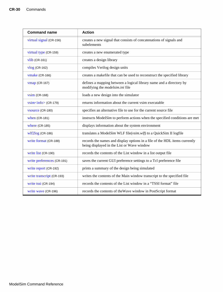
The following table provides a brief description of each ModelSim command. Command details, arguments and examples can be found at the page numbers given in the Command name column.
Command name Action
abort (CR-31) halts the execution of a macro file interrupted by a breakpoint or error
add list (CR-32) lists VHDL signals and variables, and Verilog nets and registers, and their values in the List window
add log also known as the log command. See log (CR-81)
add wave (CR-35) adds VHDL signals and variables, and Verilog nets and registers to the Wave window
alias (CR-39) creates a new Tcl procedure that evaluates the specified commands
batch_mode (CR-40) returns a 1 if ModelSim is operating in batch mode, otherwise returns a 0
bd (CR-41) deletes a breakpoint
bookmark add wave (CR-42) adds a bookmark to the specified Wave window
bookmark delete wave (CR-43) deletes bookmarks from the specified Wave window
bookmark goto wave (CR-44) zooms and scrolls a Wave window using the specified bookmark
bookmark list wave (CR-45) displays a list of available bookmarks
bp (CR-46) sets a breakpoint
cd (CR-49) changes the ModelSim local directory to the specified directory
change (CR-50) modifies the value of a VHDL variable or Verilog register variable
configure (CR-51) invokes the List or Wave widget configure command for the current default List or Wave window
dataset alias (CR-54) assigns an additional name to a dataset
dataset clear (CR-55) clears the current simulation WLF file
dataset alias (CR-54) closes a dataset
dataset info (CR-57) reports information about the specified dataset
dataset list (CR-58) lists the open dataset(s)
dataset open (CR-59) opens a dataset and references it by a logical name
dataset rename (CR-60) changes the logical name of an opened dataset
delete (CR-61) removes HDL items from either the List or Wave window
describe (CR-62) displays information about the specified HDL item
Sim Command Reference

Command reference table CR-27
disablebp (CR-63) turns off all existing breakpoints temporarily
do (CR-64) executes commands contained in a macro file
drivers (CR-65) displays in the Main window the current value and scheduled future values for all the drivers of a specified VHDL signal or Verilog net
dumplog64 (CR-66) dumps the contents of the vsim.wlf file in a readable format
echo (CR-67) displays a specified message in the Main window
edit (CR-68) invokes the editor specified by the EDITOR environment variable
enablebp (CR-69) turns on all breakpoints turned off by the disablebp command (CR-63)
environment (CR-70) displays or changes the current dataset and region/signal environment
examine (CR-71) examines one or more HDL items, and displays current values (or the values at a specified previous time) in the Main window
exit (CR-73) exits the simulator and the ModelSim application
find (CR-74) displays the full pathnames of all HDL items in the design whose names match the name specification you provide
force (CR-76) allows you to apply stimulus to VHDL signals and Verilog nets and registers, interactively
help (CR-79) displays in the Main window a brief description and syntax for the specified command
history (CR-80) lists the commands executed during the current session
log (CR-81) creates a wave log format (WLF) file containing simulation data for all HDL items whose names match the provided specifications
lshift (CR-83) takes a Tcl list as argument and shifts it in-place one place to the left, eliminating the 0th element
lsublist (CR-84) returns a sublist of the specified Tcl list that matches the specified Tcl glob pattern
modelsim (CR-85) starts the ModelSim GUI without prompting you to load a design; valid only for Windows platforms
noforce (CR-86) removes the effect of any active force (CR-76) commands on the selected HDL items
nolog (CR-87) suspends writing of data to the WLF file for the specified signals
notepad (CR-89) opens a simple text editor
noview (CR-90) closes a window in the ModelSim GUI
nowhen (CR-91) deactivates selected when (CR-181) commands
Command name Action
ModelSim Command Reference

CR-28 Commands
Model
onbreak (CR-92) specifies command(s) to be executed when running a macro that encounters a breakpoint in the source code
onElabError (CR-93) specifies one or more commands to be executed when an error is encountered during elaboration
onerror (CR-94) specifies one or more commands to be executed when a running macro encounters an error
pause (CR-95) interrupts the execution of a macro
project (CR-96) performs common operations on new projects
pwd (CR-98) displays the current directory path in the Main window
quietly (CR-99) turns off transcript echoing for the specified command
quit (CR-100) exits the simulator
radix (CR-101) specifies the default radix to be used
report (CR-102) displays the value of all simulator control variables, or the value of any simulator state variables relevant to the current simulation
restart (CR-104) reloads the design elements and resets the simulation time to zero
resume (CR-106) resumes execution of a macro file after a pause command (CR-95), or a breakpoint
run (CR-107) advances the simulation by the specified number of timesteps
searchlog (CR-109) searches one or more of the currently open logfiles for a specified condition
shift (CR-111) shifts macro parameter values down one place
show (CR-112) lists HDL items and subregions visible from the current environment
status (CR-113) lists all currently interrupted macros
step (CR-114) steps to the next HDL statement
stop (CR-115) stops simulation in batch files; used with the when command (CR-181)
tb (CR-116) displays a stack trace for the current process in the Main window
transcript (CR-117) controls echoing of commands executed in a macro file; also works at top level in batch mode
tssi2mti (CR-118) converts a vector file in Fluence Technology (formerly TSSI) Standard Events Format into a sequence of force (CR-76) and run (CR-107) commands
vcd add (CR-119) adds the specified items to the VCD file
vcd checkpoint (CR-120) dumps the current values of all VCD variables to the VCD file
vcd comment (CR-121) inserts the specified comment in the VCD file
Command name Action
Sim Command Reference

Command reference table CR-29
vcd files (CR-123) specifies the filename for the VCD file created by a vcd add command (CR-
119)
vcd flush (CR-124) flushes the contents of the VCD file buffer to the VCD file
vcd limit (CR-125) specifies the maximum size of the VCD file
vcd off (CR-126) turns off VCD dumping and records all VCD variable values as x
vcd on (CR-127) turns on VCD dumping and records the current values of all VCD variables
vcd2wlf (CR-128) translates VCD files into WLF files
vcom (CR-129) compiles VHDL design units
vdel (CR-134) deletes a design unit from a specified library
vdir (CR-135) lists the contents of a design library
vgencomp (CR-136) writes a Verilog module’s equivalent VHDL component declaration to standard output
view (CR-138) opens a ModelSim window and brings it to the front of the display
virtual count (CR-139) counts the number of currently defined virtuals that were not read in using a macro file
virtual define (CR-140) prints the definition of the virtual signal or function in the form of a command that can be used to re-create the object
virtual delete (CR-141) removes the matching virtuals
virtual describe (CR-142) prints a complete description of the data type of one or more virtual signals
virtual expand (CR-143) produces a list of all the non-virtual objects contained in the virtual signal(s)
virtual function (CR-144) creates a new signal that consists of logical operations on existing signals and simulation time
virtual hide (CR-147) sets a flag in the specified real or virtual signals so that the signals do not appear in the Signals window
virtual log (CR-148) causes the sim-mode dependent signals of the specified virtual signals to be logged by the kernel
virtual nohide (CR-150) resets the flag set by a virtual hide command
virtual nolog (CR-151) stops the logging of the specified virtual signals
virtual region (CR-153) creates a new user-defined design hierarchy region
virtual save (CR-154) saves the definitions of virtuals to a file
virtual show (CR-155) lists the full path names of all the virtuals explicitly defined
Command name Action
ModelSim Command Reference
CR-30 Commands
Model
virtual signal (CR-156) creates a new signal that consists of concatenations of signals and subelements
virtual type (CR-159) creates a new enumerated type
vlib (CR-161) creates a design library
vlog (CR-162) compiles Verilog design units
vmake (CR-166) creates a makefile that can be used to reconstruct the specified library
vmap (CR-167) defines a mapping between a logical library name and a directory by modifying the modelsim.ini file
vsim (CR-168) loads a new design into the simulator
vsim<info> (CR-179) returns information about the current vsim executable
vsource (CR-180) specifies an alternative file to use for the current source file
when (CR-181) instructs ModelSim to perform actions when the specified conditions are met
where (CR-185) displays information about the system environment
wlf2log (CR-186) translates a ModelSim WLF file(vsim.wlf) to a QuickSim II logfile
write format (CR-188) records the names and display options in a file of the HDL items currently being displayed in the List or Wave window
write list (CR-190) records the contents of the List window in a list output file
write preferences (CR-191) saves the current GUI preference settings to a Tcl preference file
write report (CR-192) prints a summary of the design being simulated
write transcript (CR-193) writes the contents of the Main window transcript to the specified file
write tssi (CR-194) records the contents of the List window in a “TSSI format” file
write wave (CR-196) records the contents of theWave window in PostScript format
Command name Action
Sim Command Reference

abort CR-31
abort
The abort command halts the execution of a macro file interrupted by a breakpoint or error. When macros are nested, you may choose to abort the last macro only, abort a specified number of nesting levels, or abort all macros. The abort command may be used within a macro to return early.
Syntax
abort[<n> | all]
Arguments
<n> | all
An integer giving the number of nested macro levels to abort; all aborts all levels. Optional. Default is 1.
See also
onbreak (CR-92), onElabError (CR-93), onerror (CR-94)
ModelSim Command Reference

CR-32 Commands
Model
add list
The add list command lists VHDL signals and variables and Verilog nets and registers in the List window, along with their associated values. User-defined buses may also be added for either language.
If no port mode is specified, add list will display all items in the selected region with names matching the item name specification.
Limitations: VHDL variables and Verilog memories can be listed using the variable’s full name only (no wildcards).
Syntax
add list[-allowconstants] [-in] [-inout] [-internal][[<item_name> | {<item_name> <options>{sig1 sig2 sig3 ...}}] ...] ... [-label <name>] [-notrigger | -trigger] [-out] [-ports] [-<radix>] [-recursive] [-width <n>]
Arguments
-allowconstants
For use with wildcard searches. Specifies that constants matching the wildcard search should be added to the List window. Optional. By default, constants are ignored because they do not change.
-in
For use with wildcard searches. Specifies that the scope of the search is to include ports of mode IN if they match the item_name specification. Optional.
-inout
For use with wildcard searches. Specifies that the scope of the search is to include ports of mode INOUT if they match the item_name specification. Optional.
-internal
For use with wildcard searches. Specifies that the scope of the search is to include internal items (non-port items) if they match the item_name specification. VHDL variables are not selected. Optional.
<item_name>
Specifies the name of the item to be listed. Optional. Wildcard characters are allowed. Variables may be added if preceded by the process name. For example,
add list myproc/int1
{<item_name> <options>{sig1 sig2 sig3 ...}}
Creates a user-defined bus in place of <item_name>; ‘sigi’ are signals to be concatenated within the user-defined bus. Optional. Specified items may be either scalars or various sized arrays as long as they have the same element enumeration type. The following option is available:
-keep
The original specified items are not removed; otherwise they are removed.
Sim Command Reference

add list CR-33
-label <name>
Specifies an alternative signal name to be displayed as a column heading in the listing. Optional. This alternative name is not valid in a force (CR-76) or examine (CR-71) command; however, it can optionally be used in a searchlog command (CR-109) with the list option.
-notrigger
Specifies that items are to be listed, but does not cause the List window to be updated when the item changes. Optional.
-out
For use with wildcard searches. Specifies that the scope of the search is to include ports of mode OUT if they match the item_name specification. Optional.
-ports
For use with wildcard searches. Specifies that the scope of the search is to include all ports. Optional. Has the same effect as specifying -in, -out, and -inout together.
-<radix>
Specifies the radix for the items that follow in the command. Optional. Valid entries (or unique abbreviations) are:
binaryoctaldecimal (or signed)unsignedhexadecimalasciisymbolicdefault
If no radix is specified for an enumerated type, the default representation is used. You can change the default radix for the current simulation using the radix command (CR-
101). You can change the default radix permanently by editing the DefaultRadix (UM-281) variable in the modelsim.ini file.
If you specify a radix for an array of a VHDL enumerated type, ModelSim converts each signal value to 1, 0, Z, or X.
-recursive
For use with wildcard searches. Specifies that the scope of the search is to descend recursively into subregions. Optional; if omitted, the search is limited to the selected region.
-trigger
Specifies that items are to be listed and causes the List window to be updated when the items change. Optional. Default.
-width <n>
Specifies the column width in characters. Optional.
ModelSim Command Reference

CR-34 Commands
Model
.
Examples
add list -r /*
Lists all items in the design.
add list *
Lists all items in the region.
add list -in *
Lists all input ports in the region.
add list a -label sig /top/lower/sig {array_sig(9 to 23)}
Displays a List window containing three columns headed a, sig, and array_sig(9 to 23).
add list clk -notrigger a b c d
Lists clk, a, b, c, and d only when clk changes.
config list -strobeperiod {100 ns} -strobestart {0 ns} -usestrobe 1 add list -notrigger clk a b c d
Lists clk, a, b, c, and d every 100 ns.
add list -hex {mybus {msb {opcode(8 downto 1)} data}}
Creates a user-defined bus named "mybus" consisting of three signals; the bus is displayed in hex.
add list vec1 -hex vec2 -dec vec3 vec4
Lists the item vec1 using symbolic values, lists vec2 in hexadecimal, and lists vec3 and vec4 in decimal.
See also
add wave (CR-35), log (CR-81), "Extended identifiers" (CR-11)
Note: -strobe, -collapse, -delta, -nodelta are no longer part of the add list (formerly the list) command. Use the configure command instead. The command equivalents for the -collapse, -delta, and -nodelta options are shown below.
5.0 or newer 4.6x
configure list -delta collapse list -collapse
configure list -delta all list -delta
configure list -delta none list -nodelta
Sim Command Reference

add wave CR-35
add wave
The add wave command adds VHDL signals and variables and Verilog nets and registers to the Wave window. It also allows specification of user-defined buses.
If no port mode is specified, add wave will display all items in the selected region with names matching the item name specification.
Limitations: VHDL variables and Verilog memories can be listed using the variable’s full name only (no wildcards).
Syntax
add wave
[-allowconstants] [-color <standard_color_name>] [-expand <signal_name>]
[-expandall <signal_name>] [-<format>] [-height <pixels>] [-in] [-inout]
[-internal]
[[<item_name> | {<item_name> [-flatten] {sig1 sig2 sig3 ...}}] ...]...
[-label <name>] [-noupdate] [-offset <offset>] [-out] [-ports] [-<radix>]
[-recursive] [-scale <scale>]
Arguments
-allowconstants
For use with wildcard searches. Specifies that constants matching the wildcard search should be added to the Wave window. Optional. By default, constants are ignored because they do not change.
-color <standard_color_name>
Specifies the color used to display a waveform. Optional. These are the standard X Window color names, or rgb value (e.g., #357f77); enclose 2-word names (“light blue”) in quotes.
-expand <signal_name>
Causes a compound signal to be expanded immediately, but only one level down. Optional. The <signal_name> is required, and may include wildcards.
-expandall <signal_name>
Causes a compound signal to be fully expanded immediately. Optional. The <signal_name> is required, and may include wildcards.
-<format>
Specifies the display format of the items:
literallogicanalog-stepanalog-interpolatedanalog-backstep
Optional. Literal waveforms are displayed as a box containing the item value. Logic signals may be U, X, 0, 1, Z, W, L, H, or ‘-’.
Analog signals are sized by -scale and by -offset. Analog-step changes to the new time before plotting the new Y. Analog-interpolated draws a diagonal line. Analog-backstep plots the new Y before moving to the new time. See "Editing and formatting HDL items in the Wave window" (UM-192).
ModelSim Command Reference

CR-36 Commands
Model
-height <pixels>
Specifies the height (in pixels) of the waveform. Optional.
-in
For use with wildcard searches. Specifies that the scope of the search is to include ports of mode IN if they match the item_name specification. Optional.
-inout
For use with wildcard searches. Specifies that the scope of the search is to include ports of mode INOUT if they match the item_name specification. Optional.
-internal
For use with wildcard searches. Specifies that the scope of the search is to include internal items (non-port items) if they match the item_name specification. Optional.
<item_name>
Specifies the names of HDL items to be included in the Wave window display. Optional. Wildcard characters are allowed. Variables may be added if preceded by the process name. For example,
add wave myproc/int1
{<item_name> [-flatten] {sig1 sig2 sig3 ...}}
Creates a user-defined bus with the name <item_name>; ‘sigi’ are signals to be concatenated within the user-defined bus. Optional. The following option is available:
-flatten
Creates an array signal that cannot be expanded to show waveforms of individual elements. Gives greater flexibility in the types of elements that can be combined, but loses the original element names. Without the -flatten option, all items must be either all scalars or all arrays of the same size. With -flatten, specified items may be either scalars or various sized arrays as long as they have the same element enumeration type.
-label <name>
Specifies an alternative name for the signal being added to the Wave window. Optional. For example,
add wave -label c clock
adds the clock signal, labeled as "c", to the Wave window.
This alternative name is not valid in a force (CR-76) or examine (CR-71) command; however, it can optionally be used in a searchlog command (CR-109) with the wave option.
-noupdate
Prevents Wave window from updating when a series of add wave commands are executed in series. Optional.
-offset <offset>
Modifies an analog waveform’s position on the display. Optional. The offset value is part of the wave positioning equation (see -scale below).
Note: You can select Edit > Combine (Wave window) to create a user-defined bus.
Sim Command Reference

add wave CR-37
-out
For use with wildcard searches. Specifies that the scope of the search is to include ports of mode OUT if they match the item_name specification. Optional.
-ports
For use with wildcard searches. Specifies that the scope of the listing is to include ports of modes IN, OUT, or INOUT. Optional.
-<radix>
Specifies the radix for the items that follow in the command. Optional. Valid entries (or any unique abbreviation) are:
binaryoctaldecimal (or signed)unsignedhexadecimalasciisymbolicdefault
If no radix is specified for an enumerated type, the default representation is used. You can change the default radix for the current simulation using the radix command (CR-
101). You can change the default radix permanently by editing the DefaultRadix (UM-281) variable in the modelsim.ini file.
If you specify a radix for an array of a VHDL enumerated type, ModelSim converts each signal value to 1, 0, Z, or X.
-recursive
For use with wildcard searches. Specifies that the scope of the search is to descend recursively into subregions. Optional; if omitted, the search is limited to the selected region.
-scale <scale>
Scales analog waveforms. Optional. The scale value is part of the wave positioning equation shown below.
The position and size of the waveform is given by:
(signal_value + <offset>) * <scale>
If signal_value + <offset> = 0, the waveform will be aligned with its name. The <scale> value determines the height of the waveform, 0 being a flat line.
ModelSim Command Reference

CR-38 Commands
Model
Examples
add wave -logic -color gold out2
Displays an item named out2. The item is specified as being a logic item presented in gold.
add wave -hex {address {a_7 a_6 a_5 a_4 a_3 a_2 a_1 a_0}}
Displays a user-defined, hex formatted bus named address.
add wave -r /*
Waves all items in the design.
add wave *
Waves all items in the region.
add wave -in *
Waves all input ports in the region.
add wave -hex {mybus {scalar1 vector1 scalar2}
Creates a user-defined bus named "mybus" consisting of three signals. Scalar1 and scalar2 are of type std_logic and vector1 is of type std_logic_vector (7 downto 1). The bus is displayed in hex.
Slices and arrays may be added to the bus using either VHDL or Verilog syntax. For example:
add wave {vector3(1)}
add wave {vector3[1]}
add wave {vector3(4 downto 0)}
add wave {vector3[4:0]}
add wave vec1 -hex vec2 -dec vec3 vec4
Adds the item vec1 to the Wave window using symbolic values, adds vec2 in hexadecimal, and adds vec3 and vec4 in decimal.
See also
add list (CR-32), log (CR-81), "Extended identifiers" (CR-11), "Concatenation directives" (CR-17)
Sim Command Reference

alias CR-39
alias
The alias command creates a new Tcl procedure that evaluates the specified commands. Used to create a user-defined alias. Any arguments passed on invocation of the alias will be passed through to the specified commands. Returns nothing.
Syntax
alias
<aka> "<cmds>"
Arguments
<aka>
Specifies the new procedure name to be used when invoking the commands. Required.
"<cmds>"
Specifies the command or commands to be evaluated when the alias is invoked. Required.
Examples
alias myquit "write list ./mylist.save; quit -f"
Creates a Tcl procedure, "myquit", that when executed, writes the contents of the List window to the file mylist.save by invoking write list (CR-190), and quits ModelSim by invoking quit (CR-100).
ModelSim Command Reference

CR-40 Commands
Model
batch_mode
The batch_mode command returns a 1 if ModelSim is operating in batch mode, otherwise returns a 0. It is typically used as a condition in an if statement.
Syntax
batch_mode
Arguments
None
Examples
Some GUI commands do not exist in batch mode. If you want to write a script that will work in or out of batch mode, you can use the batch_mode command to determine which command to use. For example:
if [batch_mode] {
log /*
} else {
add wave /*
}
See also
"Running command-line and batch-mode simulations" (UM-296)
Sim Command Reference

bd CR-41
bd
The bd command deletes a breakpoint. You must specify a filename and line number, or a specific breakpoint id#. Multiple filename/line number pairs and id#s may be specified.
Syntax
bd<filename> <line_number> | <id#>
Arguments
<filename>
Specifies the name of the source file in which the breakpoint is to be deleted. Required if an id# is not specified. The filename must match the one used previously to set the breakpoint, including whether a full pathname or a relative name was used.
<line_number>
Specifies the line number of the breakpoint to be deleted. Required if an id# is not specified.
<id#>
Specifies the id number of the breakpoint to be deleted. Required if a filename and line number are not specified.
Examples
bd alu.vhd 127
Deletes the breakpoint at line 127 in the source file named alu.vhd.
bd 5
Deletes the breakpoint with id# 5.
bd 6 alu.vhd 234
Deletes the breakpoint with id# 6 and the breakpoint at line 234 in the source file named alu.vhd.
See also
bp (CR-46), onbreak (CR-92)
ModelSim Command Reference

CR-42 Commands
Model
bookmark add wave
The bookmark add wave command creates a named reference to a specific zoom range and scroll position in the specified Wave window. Bookmarks are saved in the wave format file and are restored when the format file is read (see write format command (CR-188).
Syntax
bookmark add wave<label> <zoomrange> <topindex>
Arguments
<label>
Specifies the name for the bookmark. Required.
<zoomrange>
Specifies a list of two times with optional units. Required.
<topindex>
Specifies the vertical scroll position of the window. Required. The number identifies which item the window should be scrolled to. For example, specifying 20 means the Wave window will be scrolled down to show the 20th item.
Examples
bookmark add wave foo {{10 ns} {1000 ns}} 20
Adds a bookmark named "foo" to the current default Wave window. The bookmark marks a zoom range from 10ns to 1000ns and a scroll position of the 20th item in the window.
See also
bookmark delete wave (CR-43), bookmark goto wave (CR-44), bookmark list wave (CR-
45), write format (CR-188)
Sim Command Reference

bookmark delete wave CR-43
bookmark delete wave
The bookmark delete wave command deletes bookmarks from the specified Wave window.
Syntax
bookmark delete wave<label> [-all]
Arguments
<label>
Specifies the name of the bookmark to delete. Required unless the -all switch is used.
-all
Specifies that all bookmarks in the window be deleted. Optional.
Examples
bookmark delete wave foo
Deletes the bookmark named "foo" from the current default Wave window.
bookmark delete wave -all -window wave1
Deletes all bookmarks from the Wave window named "wave1".
See also
bookmark add wave (CR-42), bookmark goto wave (CR-44), bookmark list wave (CR-45), write format (CR-188)
ModelSim Command Reference

CR-44 Commands
Model
bookmark goto wave
The bookmark goto wave command zooms and scrolls a Wave window using the specified bookmark.
Syntax
bookmark goto wave<label>
Arguments
<label>
Specifies the bookmark to go to. Required.
See also
bookmark add wave (CR-42), bookmark delete wave (CR-43), bookmark list wave (CR-
45), write format (CR-188)
Sim Command Reference

bookmark list wave CR-45
bookmark list wave
The bookmark list wave command displays a list of available bookmarks in the Main window transcript.
Syntax
bookmark list wave
Arguments
See also
bookmark add wave (CR-42), bookmark delete wave (CR-43), bookmark goto wave (CR-
44), write format (CR-188)
ModelSim Command Reference

CR-46 Commands
Model
bp
The bp or breakpoint command either sets a file-line breakpoint or returns a list of currently set breakpoints. A set breakpoint affects every instance in the design unless the -inst <region> argument is used.
Syntax
bp
<filename> <line_number> [-id <id#>] [-inst <region>] [-disable]
[-cond {<condition_expression>}] [{<command>...}]
bp[-query <filename> [<line_number> [line_number]]]
Arguments for setting breakpoints
<filename>
Specifies the name of the source file to set the breakpoint in. Required.
<line_number>
Specifies the line number at which the breakpoint is to be set. Required.
-id <id#>
Attempts to assign this id number to the breakpoint. Optional. If the id number you specify is already used, ModelSim will return an error.
-inst <region>
Sets the breakpoint so it applies only to the specified region. Optional.
-disable
Sets the breakpoint in a disabled state. Optional. You can enable the breakpoint later using the enablebp command (CR-69). By default, breakpoints are enabled when they are set.
-cond {<condition_expression>}
Specifies condition(s) that determine whether the breakpoint is hit. Optional. If the condition is true, the simulation stops at the breakpoint. If false, the simulation bypasses the breakpoint.
The condition can be an expression with these operators:
Note: Ids for breakpoints are assigned from the same pool as those used for the when command (CR-181). So, even if you haven’t used an id number for a breakpoint, it’s possible it is used for a when statement.
Name Operator
equals ==, =
not equal !=, /=
AND &&, AND
Sim Command Reference

bp CR-47
The operands may be item names, signame’event, or constants. Subexpressions in parentheses are permitted. The command will be executed when the expression is evaluated as TRUE or 1.
The formal BNF syntax is:
condition ::= Name | { expression }
expression ::= expression AND relation| expression OR relation
| relation
relation ::= Name = Literal| Name /= Literal| Name ’ EVENT| ( expression )
Literal ::= '<char>' | “<bitstring>” | <bitstring>
The "=" operator can occur only between a Name and a Literal. This means that you cannot compare the value of two signals; i.e., Name = Name is not possible.
{<command>...}
Specifies one or more commands that are to be executed at the breakpoint. Optional. Multiple commands must be separated by semicolons (;) or placed on multiple lines. The entire command must be placed in curly braces.
Any commands that follow a run (CR-107) or step (CR-114) command will be ignored. A run or step command terminates the breakpoint sequence. This applies if macros are used within the bp command string as well. A resume (CR-106) command should not be used.
If many commands are needed after the breakpoint, they can be placed in a macro file.
Arguments for listing breakpoints
-query <filename> [<line_number> [line_number]]
Returns information about the breakpoints set in the specified file. The information returned varies depending on which arguments you specify. See the examples below for details.
OR ||, OR
Name Operator
ModelSim Command Reference

CR-48 Commands
Model
Examples
bp
Lists all existing breakpoints in the design, including the source file names, line numbers, breakpoint id#s, and any commands that have been assigned to breakpoints.
bp alu.vhd 147
Sets a breakpoint in the source file alu.vhd at line 147.
bp alu.vhd 147 {do macro.do}
Executes the macro.do macro file after the breakpoint.
bp -disable test.vhd 22 {echo [exa var1]; echo [exa var2]}
Sets a breakpoint at line 22 of the file test.vhd and examines the values of the two variables var1 and var2. This breakpoint is initially disabled. It can be enabled with the enablebp command (CR-69).
bp test.vhd 14 {if {$now /= 100} then {cont}}
Sets a breakpoint in every instantiation of the file test.vhd at line 14. When that breakpoint is executed, the command is run. This command causes the simulator to continue if the current simulation time is not 100.
bp -query testadd.vhd
Lists the line number and enabled/disabled status (1 = enabled, 0 = disabled) of all breakpoints in testadd.vhd.
bp -query testadd.vhd 48
Lists details about the breakpoint on line 48. The output comprises six pieces of information: the first item (0 or 1) designates whether a breakpoint exists on the line (1 = exists, 0 = doesn’t exist); the second item is always 1; the third item is the file name in the compiled source; the fourth item is the breakpoint line number; the fifth item is the breakpoint id; and the sixth item (0 or 1) designates whether the breakpoint is enabled (1) or disabled (0).
bp -query testadd.vhd 2 59
Lists all executable lines in testadd.vhd between lines 2 and 59.
See also
add list (CR-32), bd (CR-41), disablebp (CR-63), enablebp (CR-69), onbreak (CR-92), when (CR-181)
Note: Any breakpoints set in VHDL code and called by either resolution functions or functions that appear in a port map are ignored.
Sim Command Reference

cd CR-49
cd
The Tcl cd command changes the ModelSim local directory to the specified directory. See the Tcl man pages (Help > Tcl Man Pages) for any cd command options. Returns nothing.
Syntax
cd
[<dir>]
Arguments
<dir>
The directory to which to change. Optional. If no directory is specified, ModelSim changes to your home directory.
Description
After you change the directory with cd, ModelSim continues to write the vsim.wlf file in the directory where the first add wave (CR-35), add list (CR-32) or log (CR-81) command was executed. After completing simulation of one design, you can use the cd command to change to a new design, then use the vsim command (CR-168) to load a new design.
Use the where command (CR-185) or the Tcl pwd command to confirm the current directory.
See also
where (CR-185), vsim (CR-168), and the Tcl man page for the cd, pwd and exec commands
ModelSim Command Reference

CR-50 Commands
Model
change
The change command modifies the value of a VHDL variable or Verilog register variable. The simulator must be at a breakpoint or paused after a step command (CR-114) to change a VHDL variable.
Syntax
change<variable> <value>
Arguments
<variable>
Specifies the name of a variable. Required. The variable name must specify a scalar type or a one-dimensional array of character enumeration. You may also specify a record subelement, an indexed array, or a sliced array as long as the type is one of the above.
<value>
Defines a value for the variable. Required. The specified value must be appropriate for the type of the variable.
Examples
change count 16#FFFF
Changes the value of the variable count to the hexadecimal value FFFF.
See also
force (CR-76)
Sim Command Reference

configure CR-51
configure
The configure (config) command invokes the List or Wave widget configure command for the current default List or Wave window. To change the default window, use the view command (CR-138).
Syntax
configurelist|wave [<option> <value>]
[-delta [all | collapse | none]] [-gateduration [<duration_open>]] [-gateexpr [<expression>]] [-usegating [<value>]] [-strobeperiod [<period>]] [-strobestart [<start_time>]] [-usesignaltriggers [<value>]] [-usestrobe [<value>]]
[-childrowmargin [<pixels>]] [-gridcolor [<color>]] [-namecolwidth [<width>]] [-rowmargin [<pixels>]] [-signalnamewidth [<value>]] [-timecolor [<color>]] [-valuecolwidth [<width>]] [-vectorcolor [<color>]]
Description
The command works in three modes:
• without options or values it returns a list of all attributes and their current values
• with just an option argument (without a value) it returns the current value of that attribute
• with one or more option-value pairs it changes the values of the specified attributes to the new values
The returned information has five fields for each attribute:
• the command-line switch
• the Tk widget resource name
• the Tk class name
• the default value
• and the current value
Arguments
list|wave
Specifies either the List or Wave widget to configure. Required.
ModelSim Command Reference

CR-52 Commands
Model
<option> <value>
-bg <color>
Specifies the window background color. Optional.
-fg <color>
Specifies the window foreground color. Optional.
-selectbackground <color>
Specifies the window background color when selected. Optional.
-selectforeground <color>
Specifies the window foreground color when selected. Optional.
-font <font>
Specifies the font used in the widget. Optional.
-height <pixels>
Specifies the height in pixels of each row. Optional.
Arguments, List window only
-delta [all | collapse | none]
The all option displays a new line for each time step on which items change; collapse displays the final value for each time step; and none turns off the display of the delta column. To use -delta, -usesignaltriggers must be set to 1 (on). Optional.
-gateduration [<duration_open>]
The duration for gating to remain open beyond when -gateexpr (below) becomes false, expressed in x number of timescale units. Extends gating beyond the back edge (the last list row in which the expression evaluates to true). Optional. The default value for normal synchronous gating is zero. If -gateduration is set to a non-zero value, a simulation value will be displayed after the gate expression becomes false (if you don’t want the values displayed, set -gateduration to zero).
-gateexpr [<expression>]
Specifies the expression for trigger gating. Optional. (Use the -usegating argument to enable trigger gating.) The expression is evaluated when the List window would normally have displayed a row of data.
-usegating [<value>]
Enables triggers to be gated on (a value of 1) or off (a value of 0) by an overriding expression. Default is off. Optional. (Use the -gatexpr argument to specify the expression.) See "Setting List window display properties" (UM-142) for additional information on using gating with triggers.
-strobeperiod [<period>]
Specifies the period of the list strobe. (When using a time unit, the time value and unit must be placed in curly braces.) Optional.
-strobestart [<start_time>]
Specifies the start time of the list strobe. Optional.
-usesignaltriggers [<value>]
If 1, uses signals as triggers; if 0, not. Optional.
-usestrobe [<value>]
If 1, uses the strobe to trigger; if 0, not. Optional.
Sim Command Reference

configure CR-53
Arguments, Wave window only
-childrowmargin [<pixels>]
Specifies the distance in pixels between child signals. Optional.
-gridcolor [<color>]
Specifies the background grid color; the default is grey50. Optional.
-namecolwidth [<width>]
Specifies in pixels the width of the name column in the Wave window. Optional.
-rowmargin [<pixels>]
Specifies the distance in pixels between top-level signals.
-signalnamewidth [<value>]
Controls the number of hierarchical regions displayed as part of a signal name shown in the waveform window. Optional. Default of 0 displays the full path. 1 displays only the leaf path element, 2 displays the last two path elements, and so on.
-timecolor [<color>]
Specifies the time axis color; the default is green. Optional.
-valuecolwidth [<width>]
Specifies in pixels the width of the value column in the Wave window.
-vectorcolor [<color>]
Specifies the vector waveform color; the default is yellow. Optional.
Examples
config list -strobeperiod
Displays the current value of the strobeperiod attribute.
config list -strobeperiod {50 ns} -strobestart 0 -usestrobe 1
Sets the strobe waveform and turns it on.
config wave -vectorcolor blue
Sets the wave vector color to blue.
config wave -signalnamewidth 1
Sets display in current Wave window to show only leaf path of each signal.
See also
view (CR-138)
ModelSim Command Reference

CR-54 Commands
Model
dataset alias
The dataset alias command assigns an additional name (alias) to a dataset. The dataset can then be referenced by that alias. A dataset can have any number of aliases, but all dataset names and aliases must be unique.
Syntax
dataset alias <dataset_name> <alias_name>
Arguments
<dataset_name>
Specifies the name of the dataset to which to assign the alias. Required.
<alias_name>
Specifies the alias name to assign to the dataset. Optional. If you don’t specify an alias_name, ModelSim lists current aliases for the specified dataset_name.
See also
dataset list (CR-58), dataset open (CR-59), dataset rename (CR-60)
Sim Command Reference

dataset clear CR-55
dataset clear
The dataset clear command removes all event data from the current simulation WLF file while keeping all currently logged signals logged. Subsequent run commands will continue to accumulate data in the WLF file.
Syntax
dataset clear
Example
add wave *run 100000nsdataset clearrun 100000ns
Clears data in the WLF file from time 0ns to 100000ns, then logs data into the WLF file from time 100000ns to 200000ns.
See also
"WLF files (datasets)" (UM-104), log (CR-81)
ModelSim Command Reference

CR-56 Commands
Model
dataset close
The dataset close command closes an active dataset. To open a dataset, use the dataset open command (CR-59).
Syntax
dataset close <logicalname> | [-all]
Arguments
<logicalname>
Specifies the logical name of the dataset or alias you wish to close. Required if -all isn’t used.
-all
Closes all open datasets including the simulation. Optional.
See also
dataset open (CR-59)
Sim Command Reference

dataset info CR-57
dataset info
The dataset info command reports a variety of information about a dataset.
Syntax
dataset info option <dataset_name>
Arguments
option
Identifies what information you want reported. Required. Only one option per command is allowed. The current options include:
name - Returns the actual name of the dataset. Useful for identifying the real dataset name of an alias.
file - Returns the name of the WLF file associated with the dataset.
exists - Returns "1" if the dataset exists; "0" if it doesn’t.
<dataset_name>
Specifies the name of the dataset or alias for which you want information. Required.
See also
dataset alias (CR-54), dataset list (CR-58), dataset open (CR-59)
ModelSim Command Reference

CR-58 Commands
Model
dataset list
The dataset list command lists all active datasets.
Syntax
dataset list-long
Arguments
-long
Lists the filename corresponding to each dataset’s or alias’ logical name. Optional.
See also
dataset alias (CR-54), dataset rename (CR-60)
Sim Command Reference

dataset open CR-59
dataset open
The dataset open command opens a WLF file (representing a prior simulation) and assigns it the logical name that you specify. To close a dataset, use dataset close.
Syntax
dataset open<filename> [<logicalname>]
Arguments
<filename>
Specifies the WLF file to open as a view-mode dataset. Required.
<logicalname>
Specifies the logical name for the dataset. Optional. This is a prefix that will identify the dataset in the current session. By default the dataset prefix will be the name of the specified WLF file.
Examples
dataset open last.wlf test
Opens the dataset file last.wlf and assigns it the logical name test.
See also
dataset alias (CR-54), dataset list (CR-58), dataset rename (CR-60), vsim (CR-168) -view option
ModelSim Command Reference

CR-60 Commands
Model
dataset rename
The dataset rename command changes the logical name of a dataset to the new name you specify.
Syntax
dataset rename<logicalname> <newlogicalname>
Arguments
<logicalname>
Specifies the existing logical name of the dataset. Required.
<newlogicalname>
Specifies the new logical name for the dataset. Required.
Examples
dataset rename test test2
Renames the dataset file "test" to "test2".
See also
dataset alias (CR-54), dataset list (CR-58), dataset open (CR-59)
Sim Command Reference

delete CR-61
delete
The delete command removes HDL items from either the List or Wave window.
Syntax
deletelist | wave [-window <wname>] <item_name>
Arguments
list | wave
Specifies the target window for the delete command. Required.
-window <wname>
Specifies the name of the List or Wave window to target for the delete command (the view command (CR-138) allows you to create more than one List or Wave window). Optional. If no window is specified the default window is used; the default window is determined by the most recent invocation of the view command (CR-138).
<item_name>
Specifies the name of an item. Required. Must match an item name used in an add list (CR-32) or add wave (CR-35) command. Multiple item names may be specified. Wildcard characters are allowed.
Examples
delete list -window list2 vec2
Removes the item vec2 from the list2 window.
See also
add list (CR-32), add wave (CR-35), and "Wildcard characters" (CR-13)
ModelSim Command Reference

CR-62 Commands
Model
describe
The describe command displays information about the specified HDL item. The description is displayed in the Main window (UM-123). The following kinds of items can be described:
• VHDLsignals, variables, and constants
• Verilognets and registers
All but VHDL variables and constants may be specified as hierarchical names. VHDL variables and constants can be described only when visible from the current process that is either selected in the Process window or is the currently executing process (at a breakpoint for example).
Syntax
describe<name>
Arguments
<name>
Specifies the name of an HDL item. Wildcards are accepted. Required.
Sim Command Reference

disablebp CR-63
disablebp
The disablebp command turns off breakpoints and when statements. To turn the breakpoints or when statements back on again, use the enablebp command (CR-69).
Syntax
disablebp [<id#>]
Arguments
<id#>
Specifies a breakpoint or when statement id to disable. No other breakpoints or when statements are affected. Optional.
See also
bd (CR-41), bp (CR-46), onbreak (CR-92), resume (CR-106), when (CR-181)
ModelSim Command Reference

CR-64 Commands
Model
do
The do command executes commands contained in a macro file. A macro file can have any name and extension. An error encountered during the execution of a macro file causes its execution to be interrupted, unless an onerror command (CR-94), onbreak command (CR-
92), or the OnErrorDefaultAction Tcl variable has specified the resume command (CR-106).
Syntax
do<filename> [<parameter_value>]
Arguments
<filename>
Specifies the name of the macro file to be executed. Required. The name can be a pathname or a relative file name.
Pathnames are relative to the current working directory if the do command is executed from the command line. If the do command is executed from another macro file, pathnames are relative to the directory of the calling macro file. This allows groups of macro files to be moved to another directory and still work.
<parameter_value>
Specifies values that are to be passed to the corresponding parameters $1 through $9 in the macro file. Optional. Multiple parameter values must be separated by spaces. If you specify fewer parameter values than the number of parameters used in the macro, the unspecified values are treated as empty strings in the macro.
Note that there is no limit on the number of parameters that can be passed to macros, but only nine values are visible at one time. You can use the shift command (CR-111) to see the other parameters. The argc (UM-289) simulator state variable returns the number of parameters passed.
Examples
do macros/stimulus 100
This command executes the file macros/stimulus, passing the parameter value 100 to $1 in the macro file.
do testfile design.vhd 127
If the macro file testfile contains the line bp $1 $2, this command would place a breakpoint in the source file named design.vhd at line 127.
See also
See "Source code security and -nodebug" (UM-297). ModelSim can search for DO files based on the path list specified by the DOPATH (UM-275) environment variable. A DO file can also be called by modelsim.ini at startup (see "Using a startup file" (UM-285)). The Main transcript can be saved as a macro (see the write transcript command (CR-193)).
Sim Command Reference

drivers CR-65
drivers
The drivers command displays in the Main window the current value and scheduled future values for all the drivers of a specified VHDL signal or Verilog net. The driver list is expressed relative to the top-most design signal/net connected to the specified signal/net. If the signal/net is a record or array, each subelement is displayed individually. This command reveals the operation of transport and inertial delays and assists in debugging models.
Syntax
drivers<item_name>
Arguments
<item_name>
Specifies the name of the signal or net whose values are to be shown. Required. All signal or net types are valid. Multiple names and wildcards are accepted.
ModelSim Command Reference

CR-66 Commands
Model
dumplog64
The dumplog64 command dumps the contents of the vsim.wlf file in a readable format to stdout. The vsim.wlf file cannot be opened for writing in a simulation when you use this command.
The dumplog64 command can be invoked only from an operating system command prompt.
Syntax
dumplog64<filename>
Arguments
<filename>
The name of the WLF file to be created. Required.
Sim Command Reference

echo CR-67
echo
The echo command displays a specified message in the Main window.
Syntax
echo[<text_string>]
Arguments
<text_string>
Specifies the message text to be displayed. Optional. If the text string is surrounded by quotes, blank spaces are displayed as entered. If quotes are omitted, two or more adjacent blank spaces are compressed into one space.
Examples
echo “The time is $now ns.”
If the current time is 1000 ns, this command produces the message:
The time is 1000 ns.
If the quotes are omitted, all blank spaces of two or more are compressed into one space.
echo The time is $now ns.
If the current time is 1000ns, this command produces the message:
The time is 1000 ns.
echo can also use command substitution, such as:
echo The hex value of counter is [examine -hex counter].
If the current value of counter is 21 (15 hex), this command produces:
The hex value of counter is 15.
ModelSim Command Reference
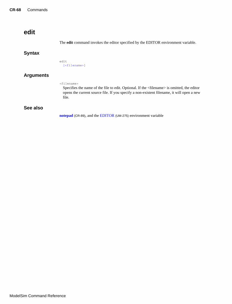
CR-68 Commands
Model
edit
The edit command invokes the editor specified by the EDITOR environment variable.
Syntax
edit[<filename>]
Arguments
<filename>
Specifies the name of the file to edit. Optional. If the <filename> is omitted, the editor opens the current source file. If you specify a non-existent filename, it will open a new file.
See also
notepad (CR-89), and the EDITOR (UM-275) environment variable
Sim Command Reference

enablebp CR-69
enablebp
The enablebp command turns on breakpoints and when statements that were turned off by the disablebp command (CR-63).
Syntax
enablebp [<id#>]
Arguments
<id#>
Specifies a breakpoint or when statement id to enable. No other breakpoints or when statements are affected. Optional.
See also
bd (CR-41), bp (CR-46), onbreak (CR-92), resume (CR-106), when (CR-181)
ModelSim Command Reference

CR-70 Commands
Model
environment
The environment, or env command, allows you to display or change the current dataset and region/signal environment.
Syntax
environment[-dataset] [-nodataset] [<dataset_prefix>[<pathname>]]
Arguments
-dataset
Displays the specified environment pathname with a dataset prefix. Optional. Dataset prefixes are displayed by default if more than one dataset is open during a simulation session.
-nodataset
Displays the specified environment pathname without a dataset prefix. Optional.
<dataset_prefix>
Changes all unlocked windows to the specified dataset context. Optional. The prefix is the logical name of the dataset followed by a colon (e.g., "sim:"). If the <pathname> argument is specified as well, it will change the environment to that specified context. If <pathname> is omitted, the environment reflects the previously set context.
<pathname>
Specifies the pathname to which the current region/signal environment is to be changed. Optional. If omitted the command causes the pathname of the current region/signal environment to be displayed.
Multiple levels of a pathname must be separated by the character specified in the PathSeparator (UM-282). A single path separator character can be entered to indicate the top level. Two dots (..) can be entered to move up one level.
Examples
env
Displays the pathname of the current region/signal environment.
env -dataset test
Changes all unlocked windows to the context of the "test" dataset.
env test:/top/foo
Changes all unlocked windows to the context "test: /top/foo".
env blk1/u2
Moves down two levels in the design hierarchy.
env /
Moves to the top level of the design hierarchy.
Sim Command Reference

examine CR-71
examine
The examine, or exa command, examines one or more HDL items, and displays current values (or the values at a specified previous time) in the Main window (UM-123).
The following items can be examined at any time:
• VHDLsignals and process variables
• Verilognets and register variables
To examine a VHDL variable, the simulator must be paused after a step command (CR-114), a breakpoint, or you can specify a process label with the name. To display a previous value, specify the desired time using the -time option.
Virtual signals and functions may also be examined within the GUI (actual signals are examined in the kernel).
Syntax
examine[-time <time>] [-delta <delta>] [-env <path>] [-name] [-<radix>] [-value] <name>...
Arguments
-time <time>
Specifies the time value between 0 and $now for which to examine the items. Optional.
If the <time> field uses a unit, the value and unit must be placed in curly braces. For example, the following are equivalent for ps resolution:
exa -time {3.6 ns} signal_aexa -time 3600 signal_a
-delta <delta>
Specifies a simulation cycle at the specified time from which to fetch the value. The default is to use the last delta of the time step. Optional.
-env <path>
Specifies a path to look for a signal name. Optional.
-name
Displays signal name(s) along with the value(s). Optional. Default is -value behavior (see below).
-<radix>
Specifies the radix for the items that follow in the command. Optional. Valid entries (including unique abbreviations) are:
binaryoctaldecimal (default for integers) or signedhexadecimalunsignedascii
ModelSim Command Reference

CR-72 Commands
Model
symbolicdefault
Entries may be truncated to any length, for example, -binary could be expressed as -b or -bin, etc. You can change the default radix for the current simulation using the radix command (CR-101). You can change the default radix permanently by editing the DefaultRadix (UM-281) variable in the modelsim.ini file.
-value
Returns value(s) as a curly-braces separated Tcl list. Default. Use to toggle off a previous use of -name.
<name>...
Specifies the name of any HDL item. Required. All item types are allowed, except those of the type file. Multiple names and wildcards are accepted. To examine a VHDL variable you can add a process label to the name. For example (make certain to use two underscore characters):
exa line__36/i
Sim Command Reference

exit CR-73
exit
The exit command exits the simulator and the ModelSim application.
Syntax
exit[-force]
Argument
-force
Quits without asking for confirmation. Optional; if this argument is omitted, ModelSim asks you for confirmation before exiting.
Note: If you want to stop the simulation using a when command (CR-181), you must use a stop command (CR-115) within your when statement. DO NOT use an exit command or a quit command (CR-100). The stop command acts like a breakpoint at the time it is evaluated.
ModelSim Command Reference
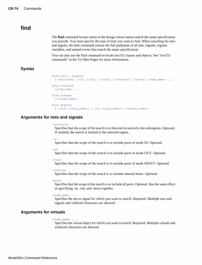
CR-74 Commands
Model
find
The find command locates items in the design whose names match the name specification you provide. You must specify the type of item you want to find. When searching for nets and signals, the find command returns the full pathname of all nets, signals, register variables, and named events that match the name specification.
You can also use the find command to locate incrTcl classes and objects. See "incrTcl commands" in the Tcl Man Pages for more information.
Syntax
find nets | signals[-recursive] [-in] [-out] [-inout] [-internal] [-ports] <item_name> ...
find virtuals<item_name> ...
find classes[<class_name>]
find objects[-class <class_name>] [-isa <class_name>] [<object_name>]
Arguments for nets and signals
-recursive
Specifies that the scope of the search is to descend recursively into subregions. Optional. If omitted, the search is limited to the selected region.
-in
Specifies that the scope of the search is to include ports of mode IN. Optional.
-out
Specifies that the scope of the search is to include ports of mode OUT. Optional.
-inout
Specifies that the scope of the search is to include ports of mode INOUT. Optional.
-internal
Specifies that the scope of the search is to include internal items. Optional.
-ports
Specifies that the scope of the search is to include all ports. Optional. Has the same effect as specifying -in, -out, and -inout together.
<item_name> ...
Specifies the net or signal for which you want to search. Required. Multiple nets and signals and wildcard characters are allowed.
Arguments for virtuals
<item_name> ...
Specifies the virtual object for which you want to search. Required. Multiple virtuals and wildcard characters are allowed.
Sim Command Reference

find CR-75
Arguments for classes
<class_name>
Specifies the incrTcl class for which you want to search. Optional. Wildcard characters are allowed. The options for class_name include nets, objects, signals, and virtuals. If you do not specify a class name, the command returns all classes in the current namespace context. See "incrTcl commands" in the Tcl Man Pages for more information.
Arguments for objects
-class <class_name>
Restricts the search to objects whose most-specific class is class_name. Optional.
-isa <class_name>
Restricts the search to those objects that have class_name anywhere in their heritage. Optional.
<object_name>
Specifies the incrTcl object for which you want to search. Optional. Wildcard characters are allowed. If you do not specify an object name, the command returns all objects in the current namespace context. See "incrTcl commands" in the Tcl Man Pages for more information.
Examples
find signals -r /*
Finds all signals in the entire design.
find nets -in /top/xy*
Finds all input signals in region /top that begin with the letters "xy".
See also
"Wildcard characters" (CR-13)
ModelSim Command Reference

CR-76 Commands
Model
force
The force command allows you to apply stimulus interactively to VHDL signals and Verilog nets and registers. Since force commands (like all commands) can be included in a macro file, it is possible to create complex sequences of stimuli.
You can force Virtual signals (UM-110) if the number of bits corresponds to the signal value. You cannot force virtual functions. In VHDL and mixed models, you cannot force an input port that is mapped at a higher level or that has a conversion function on the input.
Syntax
force[-freeze | -drive | -deposit] [-cancel <period>] [-repeat <period>] <item_name> <value> [<time>] [, <value> <time> ...]
Arguments
-freeze
Freezes the item at the specified value until it is forced again or until it is unforced with a noforce command (CR-86). Optional.
-drive
Attaches a driver to the item and drives the specified value until the item is forced again or until it is unforced with a noforce command (CR-86). Optional.
This option is illegal for unresolved signals.
-deposit
Sets the item to the specified value. The value remains until there is a subsequent driver transaction, or until the item is forced again, or until it is unforced with a noforce command (CR-86). Optional.
If one of the -freeze, -drive, or -deposit options is not used, then -freeze is the default for unresolved items and -drive is the default for resolved items.
If you prefer -freeze as the default for resolved and unresolved VHDL signals, change the default force kind in the DefaultForceKind (UM-280) preference variable.
-cancel <period>
Cancels the force command after the specified <period> of current time units. Cancellation occurs at the last simulation delta cycle of a time unit. A value of zero cancels the force at the end of the current time period. Optional.
-repeat <period>
Repeats the force command, where <period> is the time at which to start repeating the cycle. A repeating force command will force a value before other non-repeating force commands that occur in the same time step. Optional.
<item_name>
Specifies the name of the HDL item to be forced. Required. A wildcard is permitted only if it matches one item. See "HDL item pathnames" (CR-10) for the full syntax of an item name. The item name must specify a scalar type or a one-dimensional array of character enumeration. You may also specify a record subelement, an indexed array, or a sliced array, as long as the type is one of the above. Required.
Sim Command Reference

force CR-77
<value>
Specifies the value to which the item is to be forced. The specified value must be appropriate for the type. Required.
A VHDL one-dimensional array of character enumeration can be forced as a sequence of character literals or as a based number with a radix of 2, 8, 10 or 16. For example, the following values are equivalent for a signal of type bit_vector (0 to 3):
<time>
Specifies the time to which the value is to be applied. The time is relative to the current time unless an absolute time is specified by preceding the value with the character @. If the time units are not specified, then the default is the resolution units selected at simulation start-up. Optional.
A zero-delay force command causes the change to occur in the current (rather than the next) simulation delta cycle.
Examples
force input1 0
Forces input1 to 0 at the current simulator time.
force bus1 01XZ 100 ns
Forces bus1 to 01XZ at 100 nanoseconds after the current simulator time.
force bus1 16#f @200
Forces bus1 to 16#F at the absolute time 200 measured in the resolution units selected at simulation start-up.
force input1 1 10, 0 20 -r 100
Forces input1 to 1 at 10 time units after the current simulation time and to 0 at 20 time units after the current simulation time. This cycle repeats starting at 100 time units after the current simulation time, so the next transition is to 1 at 100 time units after the current simulation time.
force input1 1 10 ns, 0 {20 ns} -r 100ns
Similar to the previous example, but also specifies the time units. Time unit expressions preceding the "-r" must be placed in curly braces.
Value Description
1111 character literal sequence
2#1111 binary radix
10#15 decimal radix
16#F hexadecimal radix
Note: For based numbers in VHDL, ModelSim translates each 1 or 0 to the appropriate value for the number’s enumerated type. The translation is controlled by the translation table in the pref.tcl file. If ModelSim cannot find a translation for 0 or 1, it uses the left bound of the signal type (type’left) for that value.
ModelSim Command Reference

CR-78 Commands
Model
force s 1 0, 0 100 -repeat 200 -cancel 1000
Forces signal s to alternate between values 1 and 0 every 100 time units until time 1000. Cancellation occurs at the last simulation delta cycle of a time unit. So,
force s 1 0 -cancel 0
will force signal s to 1 for the duration of the current time period.
See also
noforce (CR-86), change (CR-50)
Note: You can configure defaults for the force command by setting the DefaultForceKind variable in the modelsim.ini file. See "Force command defaults" (UM-
285).
Sim Command Reference

help CR-79
help
The help command displays in the Main window a brief description and syntax for the specified command.
Syntax
help[<command> | <topic>]
Arguments
<command>
Specifies the command for which you want help. The entry is case and space sensitive. Optional.
<topic>
Specifies a topic for which you want help. The entry is case and space sensitive. Optional. Specify one of the following six topics:
Examples
help examine
Returns:
# examine: The examine, or exa command, examines one or more HDL items,and displays current values or the values at a specified previous time.
# Usage: examine [-time time] [-context] [-delta delta] [-env path] [-expr expression] [-fullpath] [-radix] [-value] [-name] name...
help Debugging
Returns:
# debugging: -nousage-
#Usage: debugging See these commands for debugging operations: bp bd when examine step run change add delete force view.
Topic Description
commands Lists all available commands and topics
debugging Lists debugging commands
execution Lists commands that control execution of your simulation.
Tcl Lists all available Tcl commands.
Tk Lists all available Tk commands
incrTCL Lists all available incrTCL commands
ModelSim Command Reference

CR-80 Commands
Model
history
The history command lists the commands you have executed during the current session. History is a Tcl command. For more information, consult the Tcl Man Pages.
Syntax
history[clear] [keep <value>]
Arguments
clear
Clears the history buffer. Optional.
keep <value>
Specifies the number of executed commands to keep in the history buffer. Optional. The default is 50.
Sim Command Reference

log CR-81
log
The log command creates a wave log format (WLF) file containing simulation data for all HDL items whose names match the provided specifications. Items (VHDL signals and variables, and Verilog nets and registers) that are displayed using the add list (CR-32) and add wave (CR-35) commands are automatically recorded in the WLF file. The log is stored in a WLF file (formerly a WAV file) in the working directory. By default the file is named vsim.wlf. You can change the default name using the -wlf option of the vsim (CR-168) command.
If no port mode is specified, the WLF file contains data for all items in the selected region whose names match the item name specification.
The WLF file is the source of data for the List and Wave windows. An item that has been logged and is subsequently added to the List or Wave window will have its complete history back to the start of logging available for listing and waving.
Limitations: Verilog memories and VHDL variables can be logged using the variable’s full name only (no wildcards).
Syntax
log[-recursive] [-in] [-out] [-inout] [-ports] [-internal] [-howmany] <item_name>
Arguments
-recursive
Specifies that the scope of the search is to descend recursively into subregions. Optional; if omitted, the search is limited to the selected region.
-in
Specifies that the WLF file is to include data for ports of mode IN whose names match the specification. Optional.
-out
Specifies that the WLF file is to include data for ports of mode OUT whose names match the specification. Optional.
-inout
Specifies that the WLF file is to include data for ports of mode INOUT whose names match the specification. Optional.
-ports
Specifies that the scope of the search is to include all ports. Optional.
-internal
Specifies that the WLF file is to include data for internal items whose names match the specification. Optional.
-howmany
Returns an integer indicating the number of signals found. Optional.
ModelSim Command Reference

CR-82 Commands
Model
<item_name>
Specifies the item name which you want to log. Required. Multiple item names may be specified. Wildcard characters are allowed.
Examples
log -r /*
Logs all items in the design.
log -out *
Logs all output ports in the current design unit.
See also
add list (CR-32), add wave (CR-35), nolog (CR-87), and "Wildcard characters" (CR-13)
Note: The log command is also known as the "add log" command.
Sim Command Reference

lshift CR-83
lshift
The lshift command takes a Tcl list as an argument and shifts it in-place, one place to the left, eliminating the 0th element. The number of shift places may also be specified. Returns nothing.
Syntax
lshift<list> [<amount>]
Arguments
<list>
Specifies the Tcl list to target with lshift. Required.
<amount>
Specifies the number of places to shift. Optional. Default is 1.
Examplesproc myfunc args {
# throws away the first two arguments
lshift args 2
...
}
See also
See the Tcl man pages (Help > Tcl Man Pages) for details.
ModelSim Command Reference

CR-84 Commands
Model
lsublist
The lsublist command returns a sublist of the specified Tcl list that matches the specified Tcl glob pattern.
Syntax
lsublist<list> <pattern>
Arguments
<list>
Specifies the Tcl list to target with lsublist. Required.
<pattern>
Specifies the pattern to match within the <list> using Tcl glob-style matching. Required.
Examples
In the example below, variable ‘t’ returns "structure signals source".set window_names "structure signals variables process source wave list dataflow"
set t [lsublist $window_names s*]
See also
The set command is a Tcl command. See the Tcl man pages (Help > Tcl Man Pages) for details.
Sim Command Reference

modelsim CR-85
modelsim
The modelsim command starts the ModelSim GUI without prompting you to load a design. This command may be invoked in one of three ways:
from the DOS promptfrom a ModelSim shortcutfrom the Windows Start > Run menu
To use modelsim arguments with a shortcut, add them to the target line of the shortcut’s properties. (Arguments work on the DOS command line too, of course.)
The simulator may be invoked from either the MODELSIM prompt after the GUI starts or from a DO file called by modelsim.
Syntax
modelsim[-do <macrofile>] [-project <project file>]
Arguments
-do <macrofile>
Specifies the DO file to execute when modelsim is invoked. Optional.
-project <project file>
Specifies the modelsim.ini file to load for this session. Optional.
See also
vsim (CR-168), do (CR-64), and "Using a startup file" (UM-285)
Note: In addition to the macro called by this argument, if a DO file is specified by the STARTUP variable in modelsim.ini, it will be called when the vsim command (CR-168) is invoked.
ModelSim Command Reference

CR-86 Commands
Model
noforce
The noforce command removes the effect of any active force (CR-76) commands on the selected HDL items. The noforce command also causes the item’s value to be re-evaluated.
Syntax
noforce<item_name> ...
Arguments
<item_name>
Specifies the name of a item. Required. Must match an item name used in a previous force command (CR-76). Multiple item names may be specified. Wildcard characters are allowed.
See also
force (CR-76) and "Wildcard characters" (CR-13)
Sim Command Reference

nolog CR-87
nolog
The nolog command suspends writing of data to the wave log format (WLF) file for the specified signals. A flag is written into the WLF file for each signal turned off, and the gui displays "-No Data-" for the signal(s) until logging (for the signal(s)) is turned back on.
Logging can be turned back on by issuing another log command (CR-81) or by doing a nolog -reset.
Because use of the nolog command adds new information to the WLF file, WLF files created when using the nolog command cannot be read by older versions of the simulator. If you are using dumplog64.c, you will need to get an updated version.
Syntax
nolog[-all] | [-reset] | [-recursive] [-in] [-out] [-inout] [-ports] [-internal] [-howmany] <item_name> ...
Arguments
-all
Turns off logging for all signals currently logged. Optional. Must be used alone without other arguments.
-reset
Turns logging back on for all signals unlogged. Optional. Must be used alone without other arguments.
-recursive
Specifies that the scope of the search is to descend recursively into subregions. Optional; if omitted, the search is limited to the selected region.
-in
Specifies that the WLF file is to exclude data for ports of mode IN whose names match the specification. Optional.
-out
Specifies that the WLF file is to exclude data for ports of mode OUT whose names match the specification. Optional.
-inout
Specifies that the WLF file is to exclude data for ports of mode INOUT whose names match the specification. Optional.
-ports
Specifies that the scope of the search is to exclude all ports. Optional.
-internal
Specifies that the WLF file is to exclude data for internal items whose names match the specification. Optional.
-howmany
Returns an integer indicating the number of signals found. Optional.
ModelSim Command Reference

CR-88 Commands
Model
<item_name>
Specifies the item name which you want to unlog. Required. Multiple item names may be specified. Wildcard characters are allowed.
Examples
nolog -r /*
Unlogs all items in the design.
nolog -out *
Unlogs all output ports in the current design unit.
See also
add list (CR-32), add wave (CR-35), log (CR-81)
Sim Command Reference

notepad CR-89
notepad
The notepad command opens a simple text editor. It may be used to view and edit ASCII files or create new files. When a file is specified on the command line, the editor will initially come up in read-only mode. This mode can be changed from the Notepad Edit menu. See "Mouse and keyboard shortcuts" (UM-133) for a list of editing shortcuts.
Returns nothing.
Syntax
notepad[<filename>] [-r | -edit]
Arguments
<filename>
Name of the file to be displayed. Optional.
-r | -edit
Selects the notepad editing mode: -r for read-only, and -edit for edit mode. Optional. Read-only is the default.
ModelSim Command Reference

CR-90 Commands
Model
noview
The noview command closes a window in the ModelSim GUI. To open a window, use the view (CR-138) command.
Syntax
noview[*] <window_name>...
Arguments
*Wildcards can be used, for example: l* (List window), s* (Signal, Source, and Structure windows), even * alone (all windows). Optional.
<window_name>...
Specifies the ModelSim window type to close. Multiple window types may be used; at least one type (or wildcard) is required. Available window types are:
dataflow, list, process, signals, source, structure, variables, and wave
Examples
noview wave1
Closes the Wave window named "wave1".
noview l*
Closes all List windows.
noview s*
Closes all Structure, Signals, and Source windows.
See also
view (CR-138)
Sim Command Reference

nowhen CR-91
nowhen
The nowhen command deactivates selected when (CR-181) commands.
Syntax
nowhen[<label>]
Arguments
<label>
Specifies an individual when command. Optional. Wildcards may be used to select more than one when command.
Examples
when -label 99 b {echo “b changed”}…nowhen 99
This nowhen command deactivates the when (CR-181) command labeled 99.
nowhen *
This nowhen command deactivates all when (CR-181) commands.
ModelSim Command Reference

CR-92 Commands
Model
onbreak
The onbreak command is used within a macro. It specifies one or more commands to be executed when running a macro that encounters a breakpoint in the source code. Using the onbreak command without arguments will return the current onbreak command string. Use an empty string to change the onbreak command back to its default behavior (i.e., onbreak ""). In that case, the macro will be interrupted after a breakpoint occurs (after any associated bp command (CR-46) string is executed).
onbreak commands can contain macro calls.
Syntax
onbreak{[<command> [; <command>] ...]}
Arguments
<command>
Any command can be used as an argument to onbreak. If you want to use more than one command, use a semicolon to separate the commands, or place them on multiple lines. The entire command string must be placed in curly braces. It is an error to execute any commands within an onbreak command string following a run (CR-107), run -continue, or step (CR-114) command. This restriction applies to any macros or Tcl procedures used in the onbreak command string. Optional.
Examples
onbreak {exa data ; cont}
Examine the value of the HDL item data when a breakpoint is encountered. Then continue the run command (CR-107).
onbreak {resume}
Resume execution of the macro file on encountering a breakpoint.
See also
abort (CR-31), bd (CR-41), bp (CR-46), do (CR-64), onerror (CR-94), resume (CR-106), status (CR-113)
Sim Command Reference

onElabError CR-93
onElabError
The onElabError command specifies one or more commands to be executed when an error is encountered during elaboration. The command is used by placing it within the modelsim.tcl file or a macro. During initial design load onElabError may be invoked from within the modelsim.tcl file; during a simulation restart onElabError may be invoked from a macro.
Use the onElabError command without arguments to return to a prompt.
Syntax
onElabError{[<command> [; <command>] ...]}
Arguments
<command>
Any command can be used as an argument to onElabError. If you want to use more than one command, use a semicolon to separate the commands, or place them on multiple lines. The entire command string must be placed in curly braces. Optional.
See also
do (CR-64)
ModelSim Command Reference

CR-94 Commands
Model
onerror
The onerror command is used within a macro; it specifies one or more commands to be executed when a running macro encounters an error. Using the onerror command without arguments will return the current onerror command string. Use an empty string to change the onerror command back to its default behavior (i.e., onerror ""). Use onerror with a resume command (CR-106) to allow an error message to be printed without halting the execution of the macro file.
Syntax
onerror{[<command> [; <command>] ...]}
Arguments
<command>
Any command can be used as an argument to onerror. If you want to use more than one command, use a semicolon to separate the commands, or place them on multiple lines. The entire command string must be placed in curly braces. Optional.
Example
onerror {quit -f}
Forces the simulator to quit if an error is encountered while the macro is running.
See also
abort (CR-31), do (CR-64), onbreak (CR-92), resume (CR-106), status (CR-113)
Note: You can also set the global OnErrorDefaultAction Tcl variable in the pref.tcl file to dictate what action ModelSim takes when an error occurs. The onerror command is invoked only when an error occurs in the macro file that contains the onerror command. Conversely, OnErrorDefaultAction will run even if the macro does not contain a local onerror command. This can be useful when you run a series of macros from one script, and you want the same behavior across all macros.
Sim Command Reference

pause CR-95
pause
The pause command placed within a macro interrupts the execution of that macro.
Syntax
pause
Arguments
None.
Description
When you execute a macro and that macro gets interrupted, the prompt will change to:
VSIM (pause)7>
This “pause” prompt reminds you that a macro has been interrupted.
When a macro is paused, you may invoke another macro, and if that one gets interrupted, you may even invoke another — up to a nesting level of 50 macros.
If the status of nested macros gets confusing, use the status command (CR-113). It will show you which macros are interrupted, at what line number, and show you the interrupted command.
To resume the execution of the macro, use the resume command (CR-106). To abort the execution of a macro use the abort command (CR-31).
See also
abort (CR-31), do (CR-64), resume (CR-106), run (CR-107)
ModelSim Command Reference

CR-96 Commands
Model
project
The project commands are used to perform common operations on projects. Use this command outside of a simulation session.
Syntax
project[addfile <filename>] | [close] | [compileall] | [delete <project>] | [env] | [history] | [new <home_dir> <proj_name> <defaultlibrary>] | [open <project>] | [removefile <filename>]
Arguments
addfile <filename>
Adds the specified file to the current open project. Optional.
close
Closes the current project. Optional.
compileall
Compiles all files in the current project. Optional.
copy <src_project> <dest_dir> <proj_name>
Copies an existing project to a destination directory with a specified name. Optional.
delete <project>
Deletes a specified project file. Optional.
env
Returns the current project file. Optional.
history
Lists a history of manipulated projects. Optional.
new <home_dir> <proj_name> <defaultlibrary>
Creates a new project under a specified home directory with a specified name and a default library. Optional.
open <project>
Opens a specified project file, making it the current project. Changes the current working directory to the project’s directory. Optional.
removefile <filename>
Removes the specified file from the current project. Optional.
Sim Command Reference

project CR-97
Examples
The following commands make a copy of the /user/georges/design/test3 project at /user/georges/design/test4.
vsim> project history# 0 /user/george/design/test3/test3.mpf# 1 /user/george/design/test2/test2.mpf# 2 /user/george/design/test1/test1.mpf# 3 /home/prod/release/5.4/modeltech/examples/projects/mixed/mixed.mpf# 4 /home/prod/release/5.4/modeltech/examples/projects/verilog/verilog.mpf# 5 /home/prod/release/5.4/modeltech/examples/projects/vhdl/vhdl.mpfvsim> project copy !0 /user/georges/design test4
The following command makes /user/george/design/test3 the current project and changes the current working directory to /user/george/design/test3.
vsim> project open /user/george/design/test3/test3.mpf
The following command causes execution of current project library build scripts.
vsim> project compile
The following command writes the current vsim tool settings to the current project file.
vsim> project save
The following commands delete /user/georges/test2/test2.mpf
vsim> project history# 0 /user/george/design/test4/test4.mpf# 1 /user/george/design/test3/test3.mpf# 2 /user/george/design/test2/test2.mpf# 3 /user/george/design/test1/test1.mpf# 4 /home/prod/release/5.4/modeltech/examples/projects/mixed/mixed.mpf# 5 /home/prod/release/5.4/modeltech/examples/projects/verilog/verilog.mpf# 6 /home/prod/release/5.4/modeltech/examples/projects/vhdl/vhdl.mpfvsim> project delete !2
ModelSim Command Reference

CR-98 Commands
Model
pwd
The Tcl pwd command displays the current directory path in the Main window.
Returns nothing.
Syntax
pwd
Arguments
None.
Sim Command Reference

quietly CR-99
quietly
The quietly command turns off transcript echoing for the specified command.
Syntax
quietly<command>
Arguments
<command>
Specifies the command for which to disable transcript echoing. Required. Any results normally echoed by the specified command will not be written to the Main window transcript. To disable echoing for all commands use the transcript command (CR-117) with the -quietly option.
See also
transcript (CR-117)
ModelSim Command Reference

CR-100 Commands
Model
quit
The quit command exits the simulator.
Syntax
quit
Arguments
-f or -force
Quits without asking for confirmation. Optional; if this argument is omitted, ModelSim asks you for confirmation before exiting. (The -f and -force arguments are equivalent.)
-sim
Unloads the current design in the simulator without exiting ModelSim. All files opened by the simulation will be closed including the WLF file (vsim.wlf).
Note: If you want to stop the simulation using a when command (CR-181), you must use a stop command (CR-115) within your when statement. DO NOT use an exit command (CR-73) or a quit command. The stop command acts like a breakpoint at the time it is evaluated.
Sim Command Reference

radix CR-101
radix
The radix command specifies the default radix to be used for the current simulation. The command can be used at any time. The specified radix is used for all commands (force (CR-
76), examine (CR-71), change (CR-50), etc.) as well as for displayed values in the Signals, Variables, Dataflow, List, and Wave windows. You can change the default radix permanently by editing the DefaultRadix (UM-281) variable in the modelsim.ini file.
Syntax
radix[-symbolic | -binary | -octal | -decimal | -hexadecimal | -unsigned | -ascii]
Arguments
Entries may be truncated to any length. For example, -symbolic could be expressed as -s or -sy, etc. Optional.
Also, -signed may be used as an alias for -decimal. The -unsigned radix will display as unsigned decimal. The -ascii radix will display a Verilog item as a string equivalent using 8 bit character encoding.
If no arguments are used, the command returns the current default radix.
ModelSim Command Reference

CR-102 Commands
Model
report
The report command displays the value of all simulator control variables, or the value of any simulator state variables relevant to the current simulation.
Syntax
reportsimulator control | simulator state
Arguments
simulator control
Displays the current values for all simulator control variables.
simulator state
Displays the simulator state variables relevant to the current simulation.
Examples
report simulator control
Displays all simulator control variables.
# UserTimeUnit = ns # RunLength = 100 # IterationLimit = 5000 # BreakOnAssertion = 3 # DefaultForceKind = default # IgnoreNote = 0 # IgnoreWarning = 0 # IgnoreError = 0 # IgnoreFailure = 0 # CheckpointCompressMode = 1 # NumericStdNoWarnings = 0 # StdArithNoWarnings = 0 # PathSeparator = / # DefaultRadix = symbolic # DelayFileOpen = 0 # ListDefaultShortName = 1 # ListDefaultIsTrigger = 1
report simulator state
Displays all simulator state variables. Only the variables that relate to the design being simulated are displayed:
# now = 0.0 # delta = 0# library = work # entity = type_clocks # architecture = full # resolution = 1ns
Sim Command Reference

report CR-103
Viewing preference variables
Preference variables have more to do with the way things look (but not entirely) rather than controlling the simulator. You can view preference variables from the Preferences dialog box. Select the Main > Options > Edit Preferences.
See also
"Preference variables located in INI files" (UM-278), and "Preference variables located in Tcl files" (UM-287)
ModelSim Command Reference

CR-104 Commands
Model
restart
The restart command reloads the design elements and resets the simulation time to zero. Only design elements that have changed are reloaded. (Note that SDF files are always reread during a restart.) Shared libraries are handled as follows during a restart:
• Shared libraries that implement VHDL foreign architectures only are reloaded at each restart when the architecture is elaborated (unless the -keeploaded option to the vsim command (CR-168) is used).
• Shared libraries loaded from the command line and from the Veriuser entry in the modelsim.ini file remain loaded (they are not reloaded).
• Shared libraries that implement VHDL foreign subprograms remain loaded (they are not reloaded).
To handle restarts with Verilog PLI applications, you need to define a Verilog user-defined task or function, and register a misctf class of callback. See "Verilog PLI/VPI" (UM-86) for more information on the Verilog PLI.
Syntax
restart[-force] [-nobreakpoint] [-nolist] [-nolog] [-nowave]
Arguments
-force
Specifies that the simulation will be restarted without requiring confirmation in a popup window. Optional.
-nobreakpoint
Specifies that all breakpoints will be removed when the simulation is restarted. Optional. The default is for all breakpoints to be reinstalled after the simulation is restarted.
-nolist
Specifies that the current List window environment will not be maintained after the simulation is restarted. Optional. The default is for all currently listed HDL items and their formats to be maintained.
-nolog
Specifies that the current logging environment will not be maintained after the simulation is restarted. Optional. The default is for all currently logged items to continue to be logged.
-nowave
Specifies that the current Wave window environment will not be maintained after the simulation is restarted. Optional. The default is for all items displayed in the Wave window to remain in the window with the same format.
Note: You can configure defaults for the restart command by setting the DefaultRestartOptions variable in the modelsim.ini file. See "Restart command defaults" (UM-286).
Sim Command Reference

restart CR-105
See also
vsim (CR-168)
ModelSim Command Reference

CR-106 Commands
Model
resume
The resume command is used to resume execution of a macro file after a pause command (CR-95), or a breakpoint. It may be input manually or placed in an onbreak (CR-92) command string. (Placing a resume command in a bp (CR-46) command string does not have this effect.) The resume command can also be used in an onerror (CR-94) command string to allow an error message to be printed without halting the execution of the macro file.
Syntax
resume
Arguments
None.
See also
abort (CR-31), do (CR-64), onbreak (CR-92), onerror (CR-94), pause (CR-95)
Sim Command Reference

run CR-107
run
The run command advances the simulation by the specified number of timesteps.
Syntax
run[<timesteps>[<time_units>]] | -all | -continue | -next | -step | -stepover
Arguments
<timesteps>[<time_units>]
Specifies the number of timesteps for the simulation to run. The number may be fractional, or may be specified absolute by preceding the value with the character @. Optional. In addition, optional <time_units> may be specified as:
fs, ps, ns, us, ms, or sec
The default <timesteps> and <time_units> specifications can be changed during a ModelSim session by selecting Options > Simulation (Main window). See "Setting default simulation options" (UM-226). Time steps and time units may also be set with the RunLength (UM-282) and UserTimeUnit (UM-282) variables in the modelsim.ini file.
-all
Causes the simulator to run the current simulation forever, or until it hits a breakpoint or specified break event. Optional.
-continue
Continues the last simulation run after a step (CR-114) command, step -over command or a breakpoint. A run -continue command may be input manually or used as the last command in a bp (CR-46) command string. Optional.
-next
Causes the simulator to run to the next event time. Optional.
-step
Steps the simulator to the next HDL statement. Optional.
-stepover
Specifies that VHDL procedures, functions and Verilog tasks are to be executed but treated as simple statements instead of entered and traced line by line. Optional.
ModelSim Command Reference

CR-108 Commands
Model
Examples
run 1000
Advances the simulator 1000 timesteps.
run 10.4 ms
Advances the simulator the appropriate number of timesteps corresponding to 10.4 milliseconds.
run @8000
Advances the simulator to timestep 8000.
See also
step (CR-114)
Sim Command Reference

searchlog CR-109
searchlog
The searchlog command searches one or more of the currently open logfiles for a specified condition. It can be used to search for rising or falling edges, for signals equal to a specified value, or for when a generalized expression becomes true.
Syntax
searchlog[<options>] <startTime> <pattern>
If at least one match is found, it returns the time (and optionally delta) at which the last match occurred and the number of matches found, in a Tcl list:
{{<time>} <matchCount>}
where <time> is in the format <number> <unit>. If the -deltas option is specified, the delta of the last match is also returned:
{{<time>} <delta> <matchCount>}
If no matches are found, a TCL_ERROR is returned. If one or more matches are found, but less than the number requested, it is not considered an error condition, and the time of the farthest match is returned, with the count of the matches found.
Arguments
-rising | -falling | -anyedge
Specifies an edge to look for on a scalar signal. Optional. This option is ignored for compound signals. If no options are specified, the default is -anyedge.
-reverse
Specifies to search backwards in time from <startTime>. Optional.
-deltas
Indicates to test for match on simulation delta cycles. Otherwise, matches are only tested for at the end of each simulation time step. Optional.
-expr {<expr>}
Specifies a general expression of signal values and simulation time. Optional. searchlog will search until the expression evaluates to true. The expression must have a boolean result type. See "GUI_expression_format" (CR-16) for the format of the expression.
-value <string>
Specifies to search until a single scalar or compound signal takes on this value. Optional.
-count <n>
Specifies to search for the <n>-th occurrence of the match condition, where <n> is a positive integer. Optional.
-startDelta <num>
Indicates a simulation delta cycle on which to start. Optional.
-env <path>
Provides a design region to look for the signal names. Optional.
ModelSim Command Reference

CR-110 Commands
Model
<startTime>
Specifies the simulation time at which to start the search. Required. The time may be specified as an integer number of simulation units, or as {<num> <timeUnit>}, where <num> can be integer or with a decimal point, and <timeUnit> is one of the standard VHDL time units (fs, ps, ns, us, ms, sec).
<pattern>
Specifies one or more signal names or wildcard patterns of signal names to search on. Required (unless the -expr option is used).
See also
virtual signal (CR-156), virtual log (CR-148), virtual nolog (CR-151)
Sim Command Reference

shift CR-111
shift
The shift command shifts macro parameter values down one place, so that the value of parameter $2 is assigned to parameter $1, the value of parameter $3 is assigned to $2, etc. The previous value of $1 is discarded.
The shift command and macro parameters are used in macro files. If a macro file requires more than nine parameters, they can be accessed using the shift command.
To determine the current number of macro parameters, use the argc (UM-289) variable.
Syntax
shift
Arguments
None.
Description
For a macro file containing nine macro parameters defined as $1 to $9, one shift command shifts all parameter values one place to the left. If more than nine parameters are named, the value of the tenth parameter becomes the value of $9 and can be accessed from within the macro file.
See also
do (CR-64)
ModelSim Command Reference

CR-112 Commands
Model
show
The show command lists HDL items and subregions visible from the current environment. The items listed include:
• VHDLsignals and instances
• Verilognets, registers, tasks, functions, instances and memories
The show command returns its results as a formatted Tcl string; to eliminate formatting, use the Show command.
Syntax
show[-all] [<pathname>]
Arguments
-all
Display all names at and below the specified path recursively. Optional.
<pathname>
Specifies the pathname of the environment for which you want the items and subregions to be listed. Optional; if omitted, the current environment is assumed.
Examples
show
List the names of all the items and subregion environments visible in the current environment.
show /uut
List the names of all the items and subregions visible in the environment named /uut.
show sub_region
List the names of all the items and subregions visible in the environment named sub_region which is directly visible in the current environment.
See also
find (CR-74)
Sim Command Reference

status CR-113
status
The status command lists all currently interrupted macros. The listing shows the name of each interrupted macro, the line number at which it was interrupted, and prints the command itself. It also displays any onbreak (CR-92) or onerror (CR-94) commands that have been defined for each interrupted macro.
Syntax
status
Arguments
None.
Examples
The transcript below contains examples of resume (CR-106), and status commands.
VSIM (pause) 4> status# Macro resume_test.do at line 3 (Current macro)# command executing: “pause”# is Interrupted# ONBREAK commands: “resume”# Macro startup.do at line 34# command executing: “run 1000"# processing BREAKPOINT# is Interrupted# ONBREAK commands: “resume”VSIM (pause) 5> resume# Resuming execution of macro resume_test.do at line 4
See also
abort (CR-31), do (CR-64), pause (CR-95), resume (CR-106)
ModelSim Command Reference

CR-114 Commands
Model
step
The step command steps to the next HDL statement. Current values of local variables may be observed at this time using the variables window. VHDL procedures and functions and Verilog tasks and functions can optionally be skipped over. When a wait statement or end of process is encountered, time advances to the next scheduled activity. The Process and Source windows will then be updated to reflect the next activity.
Syntax
step[-over] [<n>]
Arguments
-over
Specifies that VHDL procedures and functions and Verilog tasks and functions should be executed but treated as simple statements instead of entered and traced line by line. Optional.
<n>
Any integer. Optional. Will execute ‘n’ steps before returning.
See also
run (CR-107)
Sim Command Reference

stop CR-115
stop
The stop command is used with the when command (CR-181) to stop simulation in batch files. The stop command has the same effect as hitting a breakpoint. The stop command may be placed anywhere within the body of the when command.
Syntax
stop
Arguments
None.
Use the run command (CR-107) with the -continue option to continue the simulation run, or the resume command (CR-106) to continue macro execution. If you want macro execution to resume automatically, put the resume command at the top of your macro file:
onbreak {resume}
See also
bp (CR-46), resume (CR-106), run (CR-107), when (CR-181)
Note: If you want to stop the simulation using a when command (CR-181), you must use a stop command within your when statement. DO NOT use an exit command (CR-73) or a quit command (CR-100). The stop command acts like a breakpoint at the time it is evaluated.
ModelSim Command Reference

CR-116 Commands
Model
tb
The tb (traceback) command displays a stack trace for the current process in the Main window. This lists the sequence of HDL function calls that have been entered to arrive at the current state for the active process.
Syntax
tb
Arguments
None.
Sim Command Reference

transcript CR-117
transcript
The transcript command controls echoing of commands executed in a macro file; it also works at top level in batch mode. If no option is specified, the current setting is reported.
Syntax
transcript[on | off | -q | quietly]
Arguments
on
Specifies that commands in a macro file will be echoed to the Main window as they are executed. Optional.
off
Specifies that commands in a macro file will not be echoed to the Main window as they are executed. Optional.
-q
Returns "0" if transcripting is turned off or "1" if transcripting is turned on. Useful in a Tcl conditional expression. Optional.
quietly
Turns off the transcript echo for all commands. To turn off echoing for individual commands see the quietly command (CR-99). Optional.
Examples
transcript on
Commands within a macro file will be echoed to the Main window as they are executed.
transcript
If issued immediately after the previous example, the message:
Macro transcripting is turned on.
appears in the Main window.
See also
echo (CR-67)
ModelSim Command Reference

CR-118 Commands
Model
tssi2mti
The tssi2mti command is used to convert a vector file in Fluence Technology (formerly TSSI) Standard Events Format into a sequence of force (CR-76) and run (CR-107) commands. The stimulus is written to the standard output.
The source code for tssi2mti is provided in the file tssi2mti.c in the examples directory.
Syntax
tssi2mti<signal_definition_file> [<sef_vector_file>]
Arguments
<signal_definition_file>
Specifies the name of the Fluence Technology signal definition file describing the format and content of the vectors. Required.
<sef_vector_file>
Specifies the name of the file containing vectors to be converted. If none is specified, standard input is used. Optional.
Examples
tssi2mti trigger.def trigger.sef > trigger.do
The command will produce a do file named trigger.do from the signal definition file trigger.def and the vector file trigger.sef.
tssi2mti trigger.def < trigger.sef > trigger.do
This example is exactly the same as the previous one, but uses the standard input instead.
See also
force (CR-76), run (CR-107), write tssi (CR-194)
Sim Command Reference

vcd add CR-119
vcd add
The vcd add command adds the specified items to a VCD file. The allowed items are Verilog nets and variables and VHDL signals of type bit, bit_vector, std_logic, and std_logic_vector (other types are silently ignored).
All vcd add commands must be executed at the same simulation time. The specified items are added to the VCD header and their subsequent value changes are recorded in the specified VCD file.
By default all port driver changes and internal variable changes are captured in the file. You can filter the output using arguments detailed below.
Related Verilog tasks: $dumpvars, $fdumpvars
Syntax
vcd add[-r] [-in] [-out] [-inout] [-internal] [-ports] [-file <filename>] <item_name>
Arguments
-r
Specifies that signal and port selection occurs recursively into subregions. Optional. If omitted, included signals and ports are limited to the current region.
-in
Includes only port driver changes from ports of mode IN. Optional.
-out
Includes only port driver changes from ports of mode OUT. Optional.
-inout
Includes only port driver changes from ports of mode INOUT. Optional.
-internal
Includes only internal variable or signal changes. Excludes port driver changes. Optional.
-ports
Includes only port driver changes. Excludes internal variable or signal changes. Optional.
-file <filename>
Specifies the name of the VCD file. This option should be used only when you have created multiple VCD files using the vcd files command (CR-123).
<item_name>
Specifies the Verilog or VHDL item to add to the VCD file. Required. Multiple items may be specified by separating names with spaces. Wildcards are accepted.
See also
See Chapter 9 - Value Change Dump (VCD) Files for more information on VCD files. Verilog tasks are documented in the IEEE 1364 standard.
ModelSim Command Reference

CR-120 Commands
Model
vcd checkpoint
The vcd checkpoint command dumps the current values of all VCD variables to the specified VCD file. While simulating, only value changes are dumped.
Related Verilog tasks: $dumpall, $fdumpall
Syntax
vcd checkpoint[<filename>]
Arguments
<filename>
Specifies the name of the VCD file. Optional. If omitted the command is executed on the file designated by the vcd file command (CR-122) or "dump.vcd" if vcd file was not invoked.
See also
See Chapter 9 - Value Change Dump (VCD) Files for more information on VCD files.
Sim Command Reference

vcd comment CR-121
vcd comment
The vcd comment command inserts the specified comment in the specified VCD file.
Syntax
vcd comment<comment string> [<filename>]
Arguments
<comment string>
Comment to be included in the VCD file. Required. Must be quoted by double quotation marks or curly brackets.
<filename>
Specifies the name of the VCD file. Optional. If omitted the command is executed on the file designated by the vcd file command (CR-122) or "dump.vcd" if vcd file was not invoked.
See also
See Chapter 9 - Value Change Dump (VCD) Files for more information on VCD files.
ModelSim Command Reference

CR-122 Commands
Model
vcd file
The vcd file command specifies the filename for the VCD file created by a vcd add command (CR-119). The vcd file command is optional. If used, it must be issued before any vcd add commands.
Related Verilog task: $dumpfile
Syntax
vcd file[<filename>]
Arguments
<filename>
Specifies the name of the VCD file that is created (the default is dump.vcd). Optional.
Note: vcd file is included for backward compatibility. Use the vcd files command (CR-
123) if you want to use multiple VCD files during a single simulation.
Sim Command Reference
vcd files CR-123
vcd files
The vcd files command specifies a filename for a VCD file created by a vcd add command (CR-119). The vcd files command is optional. If used, it must be issued before any vcd add commands.
Related Verilog task: $fdumpfile
Syntax
vcd files<filename>
Arguments
<filename>
Specifies the name of a VCD file to create. Required. Multiple files can be opened during a single simulation.
ModelSim Command Reference

CR-124 Commands
Model
vcd flush
The vcd flush command flushes the contents of the VCD file buffer to the specified VCD file. This command is useful if you want to create a complete vcd file without ending your current simulation.
Related Verilog tasks: $dumpflush, $fdumpflush
Syntax
vcd flush
[<filename>]
Arguments
<filename>
Specifies the name of the VCD file. Optional. If omitted the command is executed on the file designated by the vcd file command (CR-122) or "dump.vcd" if vcd file was not invoked.
See also
See Chapter 9 - Value Change Dump (VCD) Files for more information on VCD files. Verilog tasks are documented in the IEEE 1364 standard.
Sim Command Reference

vcd limit CR-125
vcd limit
The vcd limit command specifies the maximum size of a VCD file (by default, limited to available disk space). When the size of the file exceeds the limit, a comment is appended to the file and VCD dumping is disabled.
Related Verilog tasks: $dumplimit, $fdumplimit
Syntax
vcd limit<filesize> [<filename>]
Arguments
<filesize>
Specifies the maximum VCD file size in bytes. Required.
<filename>
Specifies the name of the VCD file. Optional. If omitted the command is executed on the file designated by the vcd file command (CR-122) or "dump.vcd" if vcd file was not invoked.
See also
See Chapter 9 - Value Change Dump (VCD) Files for more information on VCD files. Verilog tasks are documented in the IEEE 1364 standard.
ModelSim Command Reference

CR-126 Commands
Model
vcd off
The vcd off command turns off VCD dumping to the specified file and records all VCD variable values as x.
Related Verilog tasks: $dumpoff, $fdumpoff
Syntax
vcd off
[<filename>]
Arguments
<filename>
Specifies the name of the VCD file. Optional. If omitted the command is executed on the file designated by the vcd file command (CR-122) or "dump.vcd" if vcd file was not invoked.
See also
See Chapter 9 - Value Change Dump (VCD) Files for more information on VCD files. Verilog tasks are documented in the IEEE 1364 standard.
Sim Command Reference

vcd on CR-127
vcd on
The vcd on command turns on VCD dumping to the specified file and records the current values of all VCD variables. By default, vcd on is automatically performed at the end of the simulation time that the vcd add (CR-119) commands are performed.
Related Verilog tasks: $dumpon, $fdumpon
Syntax
vcd on
[<filename>]
Arguments
<filename>
Specifies the name of the VCD file. Optional. If omitted the command is executed on the file designated by the vcd file command (CR-122) or "dump.vcd" if vcd file was not invoked.
See also
See Chapter 9 - Value Change Dump (VCD) Files for more information on VCD files. Verilog system tasks are documented in the IEEE 1364 standard.
ModelSim Command Reference

CR-128 Commands
Model
vcd2wlf
vcd2wlf is a utility that translates a VCD (Value Change Dump) file into a WLF file that can be displayed in ModelSim using the vsim "-view" switch.
Syntax
vcd2wlf
<vcd filename> <wlf filename>
Arguments
<vcd filename>
Specifies the name of the VCD file you want to translate into a WLF file. Required.
<wlf filename>
Specifies the name of the output WLF file. Required.
Sim Command Reference

vcom CR-129
vcom
The vcom command is used to invoke VCOM, the Model Technology VHDL compiler. Use VCOM to compile VHDL source code into a specified working library (or to the work library by default).
This command may be invoked from within ModelSim or from the operating system command prompt. This command may also be invoked during simulation.
Syntax
vcom[-87] [-93] [-check_synthesis] [-defercheck] [-explicit] [-f <filename>] [-force_refresh] [-help] [-ignoredefaultbinding] [-ignorevitalerrors] [-just eapbc] [-skip eapbc] [-line <number>] [-no1164] [-noaccel <package_name>] [-nocasestaticerror][-noothersstaticerror] [-nocheck] [-nolock] [-nologo] [-novital] [-novital <function_name> ...] [-novitalcheck] [-nowarn <number>] [-pedanticerrors] [-performdefaultbinding] [-quiet] [-rangecheck] [-refresh] [-s] [-source] [-version] [-vital2000] [-work <library_name>] <filename>
Arguments
-87
Disables support for VHDL 1076-1993. This is the VCOM default. Optional. See additional discussion in the examples. Note that the default can be changed with the modelsim.ini file; see "Preference variables located in INI files" (UM-278).
-93
Specifies that the simulator is to support VHDL 1076-1993. Optional. Default is -87. See additional discussion in the examples.
-check_synthesis
Turns on limited synthesis rule compliance checking. Optional. Checks to see that signals read by a process are in the sensitivity list.
-defercheck
Defers until run-time all compile-time range checking on constant index and slice expressions . As a result, index and slice expressions with invalid constant ranges that are never evaluated will not cause compiler error messages to be issued. Optional.
-explicit
Directs the compiler to resolve ambiguous function overloading by favoring the explicit function definition over the implicit function definition. Optional. Strictly speaking, this behavior does not match the VHDL standard. However, the majority of EDA tools choose explicit operators over implicit operators. Using this switch makes ModelSim compatible with common industry practice.
-f <filename>
Specifies a file with more command line arguments. Allows complex arguments to be reused without retyping. Optional.
-force_refresh
Forces the refresh of a module. Optional. When the compiler refreshes a design unit, it checks each module’s dependencies to ensure its source has not been changed and
ModelSim Command Reference

CR-130 Commands
Model
recompiled. If the source has been changed and recompiled, the compiler will not refresh the dependent module (unless you use the -force_refresh switch). To avoid potential syntax errors caused by the source change, you should recompile the modified source rather than use this switch.
-help
Displays the command’s options and arguments. Optional.
-ignoredefaultbinding
Instructs the compiler not to generate a default binding during compilation. Optional. You must explicitly bind all components in the design to use this switch.
-ignorevitalerrors
Directs the compiler to ignore VITAL compliance errors. Optional. The compiler still reports that VITAL errors exist, but it will not stop the compilation. You should exercise caution in using this switch; as part of accelerating VITAL packages, we assume that compliance checking has passed.
-just eapbc
Directs the compiler to “just” include:e - entities
a - architectures
p - packages
b - bodies
c - configurations
Any combination in any order can be used, but one choice is required if you use this optional switch.
-skip eapbc
Directs the compiler to skip all:e - entities
a - architectures
p - packages
b - bodies
c - configurations
Any combination in any order can be used, but one choice is required if you use this optional switch.
-line <number>
Starts the compiler on the specified line in the VHDL source file. Optional. By default, the compiler starts at the beginning of the file.
-no1164
Causes the source files to be compiled without taking advantage of the built-in version of the IEEE std_logic_1164 package. Optional. This will typically result in longer simulation times for VHDL programs that use variables and signals of type std_logic.
-noaccel <package_name>
Turns off acceleration of the specified package in the source code using that package.
-nocasestaticerror
Suppresses case static warnings. Optional. VHDL standards require that case alternative choices be static at compile time. However, some expressions which are globally static
Sim Command Reference

vcom CR-131
are allowed. This switch prevents the compiler from warning on such expressions. If the -pedanticerrors switch is specified, this switch is ignored.
-noothersstaticerror
Disables warnings that result from array aggregates with multiple choices having "others" clauses that are not locally static. Optional. If the -pedanticerrors switch is specified, this switch is ignored.
-nocheck
Disables run time range checking. Default. In some designs, this results in a 2X speed increase. Range checking can be enabled using -rangecheck.
-nolock
Overrides the library lock file. Optional. Default is locked. The lock file prevents multiple users from concurrently accessing the same library. If you are a single user, disabling the lock file should not present a problem. However, using this switch can lead to a corrupt library if multiple compiles are run on the same library at the same time.
-nologo
Disables startup banner. Optional.
-novital
Causes VCOM to use VHDL code for VITAL procedures rather than the accelerated and optimized timing and primitive packages built into the simulator kernel. Optional.
-novital <function_name> ...
You can use your own VHDL code for specific functions with this option. Use one -novital <function_name> switch instance for each function.
-novitalcheck
Disables VITAL95 compliance checking if you are using VITAL 2.2b. Optional.
-nowarn <number>
Selectively disables an individual warning message. Optional. Multiple -nowarn switches are allowed. Warnings may be disabled for all compiles via the Main window Options > Compile Options menu command or the modelsim.ini file (see the "[vcom] VHDL compiler control variables" (UM-278)).
The warning message numbers are:
1 = unbound component2 = process without a wait statement3 = null range4 = no space in time literal5 = multiple drivers on unresolved signal6 = compliance checks7 = optimization messages
-pedanticerrors Forces ModelSim to error (rather than warn) on two conditions: 1) when a choice in a case statement is not a locally static expression; 2) when an array aggregate with multiple choices doesn’t have a locally static "others" choice. Optional. This argument overrides -nocasestaticerror and -noothersstaticerror (see above).
-performdefaultbinding Enables default binding when it has been disabled via the RequireConfigForAllDefaultBinding option in the modelsim.ini file. Optional.
ModelSim Command Reference

CR-132 Commands
Model
-quiet
Disable ’loading’ messages. Optional.
-rangecheck
Enables run time range checking. Range checks are disabled by default. Once enabled, they can be disabled using -nocheck argument.
-refresh
Regenerates a library image. Optional. By default, the work library is updated; use -work <library> to update a different library. See vcom "Examples" (CR-132) for more information.
-s
Instructs the compiler not to load the standard package. Optional. This argument should only be used if you are compiling the standard package itself.
-source
Displays the associated line of source code before each error message that is generated during compilation. Optional; by default, only the error message is displayed.
-version
Returns the version of the compiler as used by the licensing tools, such as "Model Technology ModelSim SE vcom 5.5 Compiler 2000.01 Jan 29 2000".
-vital2000
Turns on acceleration of vital_memory package in VITAL 2000 library. Optional.
-work <library_name>
Specifies a logical name or pathname of a library that is to be mapped to the logical library work. Optional; by default, the compiled design units are added to the work library. The specified pathname overrides the pathname specified for work in the project file.
<filename>
Specifies the name of a file containing the VHDL source to be compiled. One filename is required; multiple filenames can be entered separated by spaces or wildcards may be used, i.e., “*.vhd”.
If no filenames are given, a dialog box pops up allowing you to graphically select the options and enter a filename.
Examples
vcom example.vhd
Compiles the VHDL source code contained in the file example.vhd.
vcom -87 o_units1 o_units2vcom -93 n_unit91 n_unit92
ModelSim supports designs that use elements conforming to both the 1993 and the 1987 standards. Compile the design units separately using the appropriate switches.
Note that in the example above, the -87 switch on the first line is redundant since the VCOM default is to compile to the 1987 standard.
vcom -noaccel numeric_std example.vhd
When compiling source that uses the numeric_std package, this command turns off acceleration of the numeric_std package, located in the ieee library.
Sim Command Reference

vcom CR-133
vcom -explicit example.vhd
Although it is not obvious, the = operator is overloaded in the std_logic_1164 package. All enumeration data types in VHDL get an “implicit” definition for the = operator. So while there is no explicit = operator, there is an implicit one. This implicit declaration can be hidden by an explicit declaration of = in the same package (LRM Section 10.3). However, if another version of the = operator is declared in a different package than that containing the enumeration declaration, and both operators become visible through use clauses, neither can be used without explicit naming.
ARITHMETIC.”=”(left, right)
To eliminate that inconvenience, the VCOM command has the -explicit option that allows the explicit = operator to hide the implicit one. Allowing the explicit declaration to hide the implicit declaration is what most VHDL users expect.
vcom -work mylib -refresh
The -work option specifies mylib as the library to regenerate. -refresh rebuilds the library image without using source code, allowing models delivered as compiled libraries without source code to be rebuilt for a specific release of ModelSim (4.6 and later only).
If your library contains Verilog design units be sure to regenerate the library with vlog (CR-162) and -refresh as well. See "Regenerating your design libraries" (UM-41) for more information.
ModelSim Command Reference

CR-134 Commands
Model
vdel
The vdel command deletes a design unit from a specified library.
Syntax
vdel[-help] [-verbose] [-lib <library_name>] [-all | <design_unit> [<arch_name>]]
Arguments
-help
Displays the command’s options and arguments. Optional.
-verbose
Displays progress messages. Optional.
-lib <library_name>
Specifies the logical name or pathname of the library that holds the design unit to be deleted. Optional; by default, the design unit is deleted from the work library.
-all
Deletes an entire library. Optional. BE CAREFUL! Libraries cannot be recovered once deleted, and you are not prompted for confirmation.
<design_unit>
Specifies the entity, package, configuration, or module to be deleted. Required unless -all is used.
<arch_name>
Specifies the name of an architecture to be deleted. Optional; if omitted, all of the architectures for the specified entity are deleted. Invalid for a configuration or a package.
Examples
vdel -all
Deletes the work library.
vdel -lib synopsys -all
Deletes the synopsys library.
vdel xor
Deletes the entity named xor and all its architectures from the work library.
vdel xor behavior
Deletes the architecture named behavior of the entity xor from the work library.
vdel base
Deletes the package named base from the work library.
Sim Command Reference

vdir CR-135
vdir
The vdir command selectively lists the contents of a design library.
Syntax
vdir[-help] [-l] [-r] [-lib <library_name>] [<design_unit>]
Arguments
-help
Displays the command’s options and arguments. Optional.
-l
Prints the version of vcom or vlog that each design unit was compiled under. Also prints the object-code version number that indicates which versions of vcom/vlog and ModelSim are compatible. This example was printed by vdir -l for the counter module in the work library:
# MODULE counter
# Verilog Version: OzO;ZAVlR1jO;>KYTg2kY2
# Source directory: ..\examples\projects\mixed
# Source modified time: 944001078
# Source file: ../examples/projects/verilog/counter.v
# Opcode format: 5.4 Beta 4; VLOG EE Object version 17
# Version number: e:VQh7zF_VJYN9MbEXUG_3
# Optimized Verilog design root: 1
# Language standard: 1
-r
Prints architecture information for each entity in the output.
-lib <library_name>
Specifies the logical name or the pathname of the library to be listed. Optional; by default, the contents of the work library are listed.
<design_unit>
Indicates the design unit to search for within the specified library. If the design unit is a VHDL entity, its architectures are listed. Optional; by default, all entities, configurations, modules, and packages in the specified library are listed.
Example
vdir -lib design my_asic
Lists the architectures associated with the entity named my_asic that resides in the HDL design library called design.
ModelSim Command Reference

CR-136 Commands
Model
vgencomp
Once a Verilog module is compiled into a library, you can use the vgencomp command to write its equivalent VHDL component declaration to standard output. Optional switches allow you to generate bit or vl_logic port types; std_logic port types are generated by default.
Syntax
vgencomp[-help] [-lib <library_name>] [-b] [-s] [-v] <module_name>
Arguments
-help
Displays the command’s options and arguments. Optional.
-lib <library_name>
Specifies the pathname of the working library. If not specified, the default library work is used. Optional.
-b
Causes vgencomp to generate bit port types. Optional.
-s
Used for the explicit declaration of default std_logic port types. Optional.
-v
Causes vgencomp to generate vl_logic port types. Optional.
<module_name>
Specifies the name of the Verilog module to be accessed. Required.
Sim Command Reference

vgencomp CR-137
Examples
This example uses a Verilog module that is compiled into the work library. The module begins as Verilog source code:
module top(i1, o1, o2, io1);parameter width = 8;parameter delay = 4.5;parameter filename = "file.in";
input i1;output [7:0] o1;output [4:7] o2;inout [width-1:0] io1;
endmodule
After compiling, vgencomp is invoked on the compiled module:
vgencomp top
and writes the following to stdout:
component top
generic(width : integer := 8;delay : real := 4.500000;filename : string := "file.in"
);port(
i1 : in std_logic;o1 : out std_logic_vector(7 downto 0);o2 : out std_logic_vector(4 to 7);io1 : inout std_logic_vector);
end component;
ModelSim Command Reference

CR-138 Commands
Model
view
The view command will open a ModelSim window and bring that window to the front of the display.
To remove a window, use the noview command (CR-90).
Syntax
view[*] [-x <n>] [-y <n>] [-height <n>] [-width <n>] [-icon] <window_name>...
Arguments
*Wildcards can be used; for example: l* (List window), s* (Signal, Source, and Structure windows), even * alone (all windows). Optional.
-x <n>
Specifies the window upper-left-hand x-coordinate in pixels. Optional
-y <n>
Specifies the window upper-left-hand y-coordinate in pixels. Optional
-height <n>
Specifies the window height in pixels. Optional
-width <n>
Specifies the window width in pixels. Optional
-icon
Toggles the view between window and icon. Optional
<window_name>...
Specifies the ModelSim window type to view. Multiple window types may be used; at least one type (or wildcard) is required. Available window types are:
dataflow, list, process, signals, source, structure, variables, and wave
See also
noview (CR-90)
Sim Command Reference

virtual count CR-139
virtual count
The virtual count command counts the number of currently defined virtuals that were not read in using a macro file.
Syntax
virtual count [-kind <kind>]
Arguments
-kind <kind>
Specifies a subset of virtuals to look at. Optional. <kind> can be any of the following: signals, functions, designs, implicits, and explicits. Unique abbreviations are accepted.
-unsaved
Specifies that the count include only those virtuals that have not been saved. Optional.
See also
virtual define (CR-140), virtual save (CR-154), virtual show (CR-155), Virtual Objects (User-defined buses, and more) (UM-110)
ModelSim Command Reference

CR-140 Commands
Model
virtual define
The virtual define command prints to the Main window the definition of the virtual signal or function in the form of a command that can be used to re-create the object.
Syntax
virtual define[-kind <kind>] <path>|<wildcard>
Arguments
-kind <kind>
Specifies a subset of virtuals to look at. Optional. <kind> can be any of the following: signals, functions, designs, implicits, and explicits. Unique abbreviations are accepted.
<path>|<wildcard>
Specifies the location(s) and name(s) of the signal(s) for which you want definitions. Required.
Examples
virtual define -kind explicits *
Shows the definitions of all the virtuals you have explicitly created.
See also
virtual describe (CR-142), virtual show (CR-155), Virtual Objects (User-defined buses, and more) (UM-110)
Sim Command Reference

virtual delete CR-141
virtual delete
The virtual delete command removes the matching virtuals.
Syntax
virtual delete[-kind <kind>] <path>|<wildcard>
Arguments
-kind <kind>
Specifies a subset of virtuals to look at. Optional. <kind> can be any of the following: signals, functions, designs, implicits, and explicits. Unique abbreviations are accepted.
<path>|<wildcard>
Specifies the location(s) and name(s) of the signal(s) you want to delete. Required.
Examples
virtual delete -kind explicits *
Deletes all of the virtuals you have explicitly created.
See also
virtual signal (CR-156), virtual function (CR-144), Virtual Objects (User-defined buses, and more) (UM-110)
ModelSim Command Reference

CR-142 Commands
Model
virtual describe
The virtual describe command prints to the Main window a complete description of the data type of one or more virtual signals. Similar to the existing describe command.
Syntax
virtual describe[-kind <kind>] <path>|<wildcard>
Arguments
-kind <kind>
Specifies a subset of virtuals to look at. Optional. <kind> can be any of the following: signals, functions, designs, implicits, and explicits. Unique abbreviations are accepted.
<path>|<wildcard>
Specifies the location(s) and name(s) of the signal(s) for which you want descriptions. Required.
Examples
virtual describe -kind explicits *
Describes the data type of all virtuals you have explicitly created.
See also
virtual define (CR-140), virtual show (CR-155), Virtual Objects (User-defined buses, and more) (UM-110)
Sim Command Reference

virtual expand CR-143
virtual expand
The virtual expand command produces a list of all the non-virtual objects contained in the specified virtual signal(s). This can be used to create a list of arguments for a command that does not accept or understand virtual signals.
Syntax
virtual expand[-base] <path>|<wildcard>
Arguments
-base
Causes the root signal parent to be output in place of a subelement. Optional. For example:
vcd add [virtual expand -base myVirtualSignal]
the resulting command after substitution would be:
vcd add signala signalb signalc
<path>|<wildcard>
Specifies the locations and names of the signals to expand. Required. Any number of paths and wildcards may be used.
Examples
vcd add [virtual expand myVirtualSignal]
Adds the elements of a virtual signal to the VCD file.
In the Tcl language, the square brackets specify that the enclosed command should be executed first ("virtual expand ..."), then the result substituted into the surrounding command. So if myVirtualSignal is a concatenation of signala, signalb.rec1 and signalc(5 downto 3), the resulting command after substitution would be:
vcd add signala signalb.rec1 {signalc(5 downto 3)}
The slice of signalc is quoted in curly braces, because it contains spaces.
See also
virtual signal (CR-156), Virtual Objects (User-defined buses, and more) (UM-110)
ModelSim Command Reference

CR-144 Commands
Model
virtual function
The virtual function command creates a new signal, known only by the GUI (not the kernel), that consists of logical operations on existing signals and simulation time, as described in <expressionString>. It cannot handle bit selects and slices of Verilog registers. Please see "Syntax and conventions" (CR-5) for more details on syntax.
The virtual function will show up in the Wave and Signals windows as an expandible object if it references more than a single scalar signal. The children correspond to the inputs of the virtual function. This allows the virtual function to be "expanded" in the Wave window to see the values of each of the input waveforms, which could be useful when using virtual functions to compare two signal values.
Virtual functions can be used to gate the List window display.
Syntax
virtual function[-env <path>] [-install <path>] [-implicit] [-delay <time>] {<expressionString>} <name>
Arguments
Arguments for virtual function are the same as those for virtual signal, except for the contents of the expression string.
-env <path>
Specifies a hierarchical context for the signal names in <expressionString> so they don’t all have to be full paths. Optional.
-install <path>
Causes the newly-created signal to become a child of the specified region. If -install is not specified, the newly-created signal becomes a child of the nearest common ancestor of all objects appearing in <expressionString>. If the expression references more than one WLF file (dataset), the virtual signal will automatically be placed in region virtuals:/Functions. Optional.
-implicit
Used internally to create virtuals that are automatically saved with the List or Wave format. Optional.
-delay <time>
Specifies a value by which the virtual function will be delayed. Optional. You can use negative values to look forward in time. If units are specified, the <time> option must be enclosed in curly braces. See the examples below for more details.
{<expressionString>}
A text string expression in the MTI GUI expression format. Required. See "GUI_expression_format" (CR-16) for more information.
Sim Command Reference

virtual function CR-145
<name>
The name you define for the virtual signal. Required. Case is ignored unless installed in a Verilog region. Use alpha, numeric, and underscore characters only, unless you are using VHDL extended identifier notation. If using VHDL extended identifier notation, <name> needs to be quoted with double quotes or with curly braces.
Examples
virtual function { not /chip/section1/clk } clk_n
Creates a signal /chip/section1/clk_n which is the inverse of /chip/section1/clk.
virtual function -install /chip { (std_logic_vector) chip.vlog.rega } rega_slv
Creates a std_logic_vector equivalent of a verilog register "rega" and installs it as /chip/rega_slv.
virtual function { /chip/addr[11:0] == 0xfab } addr_eq_fab
Creates a boolean signal /chip/addr_eq_fab that is true when /chip/addr[11:0] is equal to hex "fab", and false otherwise. It is ok to mix VHDL signal path notation with Verilog part-select notation.
virtual function { gate:/chip/siga XOR rtl:/chip/siga) } siga_diff
Creates a signal that is only high during times when signal /chip/siga of the gate-level version of the design does not match /chip/siga of the rtl version of the design. Because there is no common design region for the inputs to the expression, siga_diff is installed in region virtuals:/Functions. The virtual function siga_diff can be added to the wave window, and when expanded will show the two original signals that are being compared.
virtual function -delay {10 ns} {/top/signalA AND /top/signalB} myDelayAandB
Creates a virtual signal consisting of the logical "AND" function of /top/signalA with /top/signalB, and delays it by 10 ns.
virtual function { | (gate:/chip/outbus XOR rtl:/chip/outbus) } outbus_diff
Creates a one-bit signal "outbus_diff" which is non-zero during times when any bit of a vector signal /chip/outbus of the gate-level version of the design does not match the corresponding bit of the signal in the rtl version of the design.
This expression uses the "OR-reduction" operator, which takes the logical OR of all the bits of the vector argument.
Commands fully compatible with virtual functions
add list (CR-32) add log /log (CR-81) add wave (CR-35)
delete (CR-61) describe (CR-62) ("virtual describe" is a little faster)
examine (CR-71)
find (CR-74) restart (CR-104) searchlog (CR-109)
show (CR-112)
ModelSim Command Reference

CR-146 Commands
Model
Commands not currently compatible with virtual functions
See also
drivers (CR-65) force (CR-76) noforce (CR-86)
vcd add (CR-119) when (CR-181)
virtual count (CR-139) virtual define (CR-140) virtual delete (CR-141)
virtual describe (CR-142) virtual expand (CR-143) virtual hide (CR-147)
virtual log (CR-148) virtual nohide (CR-150) virtual nolog (CR-151)
virtual region (CR-153) virtual save (CR-154) virtual show (CR-155)
virtual signal (CR-156) virtual type (CR-159) Virtual Objects (User-defined buses, and more) (UM-110)
Sim Command Reference

virtual hide CR-147
virtual hide
The virtual hide command sets a flag in the specified real or virtual signals, so those signals do not appear in the Signals window. This is used when you want to replace an expanded bus with a user-defined bus. You make the signals reappear using the virtual nohide command.
Syntax
virtual hide[-kind <kind>]|[-region <path>] <signalName>|<pattern>
Arguments
-kind <kind>
Specifies a subset of virtuals to look at. Optional. <kind> can be any of the following: signals, functions, designs, implicits, and explicits. Unique abbreviations are accepted.
-region <path>
Used in place of -kind to specify a region of design space in which to look for the signal names. Optional.
<signalName>|<pattern>
Indicates which signal names or wildcard patterns should be used in finding the signals to hide. Required. Any number of names or wildcard patterns may be used.
See also
virtual nohide (CR-150), Virtual Objects (User-defined buses, and more) (UM-110)
ModelSim Command Reference

CR-148 Commands
Model
virtual log
The virtual log command causes the sim-mode dependent signals of the specified virtual signals to be logged by the kernel. If wildcard patterns are used, it will also log any normal signals found, unless the -only option is used. You unlog the signals using the virtual nolog command.
Syntax
virtual log[-kind <kind>]|[-region <path>] [-recursive] [-only] [-in] [-out] [-inout] [-internal] [-ports] [<signalName>|<pattern>]
Arguments
-kind <kind>
Specifies a subset of virtuals to look at. Optional. <kind> can be any of the following: signals, functions, designs, implicits, and explicits. Unique abbreviations are accepted.
-region <path>
Used in place of -kind to specify a region of design space in which to look for signals to log. Optional.
-recursive
Specifies that the scope of the search is to descend recursively into subregions. Optional. If omitted, the search is limited to the selected region.
-only
Can be used with a wildcard to specify that only virtual signals (as opposed to all signals) found by the wildcard should be logged. Optional.
-in
Specifies that the kernal log data for ports of mode IN whose names match the specification. Optional.
-out
Specifies that the kernal log data for ports of mode OUT whose names match the specification. Optional.
-inout
Specifies that the kernal log data for ports of mode INOUT whose names match the specification. Optional.
-internal
Specifies that the kernal log data for internal items whose names match the specification. Optional.
-ports
Specifies that the kernal log data for all ports. Optional.
<signalName>|<pattern>
Indicates which signal names or wildcard patterns should be used in finding the signals to log. Required. Any number of names or wildcard patterns may be used.
Sim Command Reference

virtual log CR-149
See also
virtual nolog (CR-151), Virtual Objects (User-defined buses, and more) (UM-110)
ModelSim Command Reference

CR-150 Commands
Model
virtual nohide
The virtual nohide command reverses the effect of a virtual hide command. It resets the flag in the specified real or virtual signals, so those signals reappear in the Signals window.
Syntax
virtual hide|nohide[-kind <kind>]|[-region <path>] <signalName>|<pattern>
Arguments
-kind <kind>
Specifies a subset of virtuals to look at. Optional. <kind> can be any of the following: signals, functions, designs, implicits, and explicits. Unique abbreviations are accepted.
-region <path>
Used in place of -kind to specify a region of design space in which to look for the signal names. Optional.
<signalName>|<pattern>
Indicates which signal names or wildcard patterns should be used in finding the signals to expose. Required. Any number of names or wildcard patterns may be used.
See also
virtual hide (CR-147), Virtual Objects (User-defined buses, and more) (UM-110)
Sim Command Reference

virtual nolog CR-151
virtual nolog
The virtual nolog command reverses the effect of a virtual log command. It causes the sim-mode dependent signals of the specified virtual signals to be excluded ("unlogged") by the kernel. If wildcard patterns are used, it will also unlog any normal signals found, unless the -only option is used.
Syntax
virtual nolog[-kind <kind>]|[-region <path>] [-recursive] [-only] [-in] [-out] [-inout] [-internal] [-ports] [<signalName>|<pattern>]
Arguments
-kind <kind>
Specifies a subset of virtuals to look at. Optional. <kind> can be any of the following: signals, functions, designs, implicits, and explicits. Unique abbreviations are accepted.
-region <path>
Used in place of -kind to specify a region of design space in which to look for signals to unlog. Optional.
-recursive
Specifies that the scope of the search is to descend recursively into subregions. Optional. If omitted, the search is limited to the selected region.
-only
Can be used with a wildcard to specify that only virtual signals (as opposed to all signals) found by the wildcard should be unlogged. Optional.
-in
Specifies that the kernal exclude data for ports of mode IN whose names match the specification. Optional.
-out
Specifies that the kernal exclude data for ports of mode OUT whose names match the specification. Optional.
-inout
Specifies that the kernal exclude data for ports of mode INOUT whose names match the specification. Optional.
-internal
Specifies that the kernal exclude data for internal items whose names match the specification. Optional.
-ports
Specifies that the kernal exclude data for all ports. Optional.
<signalName>|<pattern>
Indicates which signal names or wildcard pattern should be used in finding the signals to unlog. Required. Any number of names or wildcard patterns may be used.
ModelSim Command Reference

CR-152 Commands
Model
See also
virtual log (CR-148), Virtual Objects (User-defined buses, and more) (UM-110)
Sim Command Reference

virtual region CR-153
virtual region
The virtual region command creates a new user-defined design hierarchy region.
Syntax
virtual region<parentPath> <regionName>
Arguments
<parentPath>
The full path to the region that will become the parent of the new region. Required.
<regionName>
The name you want for the new region. Required.
See also
virtual function (CR-144), virtual signal (CR-156), Virtual Objects (User-defined buses, and more) (UM-110)
Note: Virtual regions cannot be used in the when (CR-181) command.
ModelSim Command Reference

CR-154 Commands
Model
virtual save
The virtual save command saves the definitions of virtuals to a file.
Syntax
virtual save[-kind <kind>] [-append] [<filename>]
Arguments
-kind <kind>
Specifies a subset of virtuals to look at. Optional. <kind> can be any of the following: signals, functions, designs, implicits, and explicits. Unique abbreviations are accepted.
-append
Specifies to save ONLY THOSE VIRTUALS that are neither already saved nor those that were read in from a macro file. These unsaved virtuals are then appended to the specified or default file. Optional.
<filename>
Used for writing the virtual definitions. Optional. If you don’t specify <filename>, the default virtual filename (virtuals.do) will be used. You can specify a different default in the pref.tcl file.
See also
virtual count (CR-139), Virtual Objects (User-defined buses, and more) (UM-110)
Sim Command Reference

virtual show CR-155
virtual show
The virtual show command lists the full path names of all explicitly defined virtuals.
Syntax
virtual show[-kind <kind>]
Arguments
-kind <kind>
Specifies a subset of virtuals to look at. Optional. <kind> can be any of the following: signals, functions, designs, implicits, and explicits. Unique abbreviations are accepted.
See also
virtual define (CR-140), virtual describe (CR-142), Virtual Objects (User-defined buses, and more) (UM-110)
ModelSim Command Reference

CR-156 Commands
Model
virtual signal
The virtual signal command creates a new signal, known only by the GUI (not the kernel), that consists of concatenations of signals and subelements as specified in <expressionString>. It cannot handle bit selects and slices of Verilog registers. Please see "Syntax and conventions" (CR-5) for more details on syntax.
Syntax
virtual signal[-env <path>] [-install <path>] [-implicit] [-delay <time>] {<expressionString>} <name>
Arguments
-env <path>
Specifies a hierarchical context for the signal names in <expressionString>, so they don’t all have to be full paths. Optional.
-install <path>
Causes the newly-created signal to become a child of the specified region. If -install is not specified, the newly-created signal becomes a child of the nearest common ancestor of all objects appearing in <expressionString>. If the expression references more than one WLF file (dataset), the virtual signal will automatically be placed in region virtuals:/Signals. Optional.
-implicit
Used internally to create virtuals that are automatically saved with the List or Wave format. Optional.
-delay <time>
Specifies a value by which the virtual signal will be delayed. Optional. You can use negative values to look forward in time. If units are specified, the <time> option must be enclosed in curly braces. See the examples below for more details.
{<expressionString>}
A text string expression in the MTI GUI expression format that defines the signal and subelement concatenation. Can also be a literal constant or computed subexpression. Required. For details on syntax, please see "Syntax and conventions" (CR-5).
<name>
The name you define for the virtual signal. Required. Case is ignored unless installed in a Verilog region. Use alpha, numeric, and underscore characters only, unless you are using VHDL extended identifier notation. If using VHDL extended identifier notation, <name> needs to be quoted with double quotes or with curly braces.
Sim Command Reference

virtual signal CR-157
Examples
virtual signal -env sim:/chip/alu { (concat_range (4 downto 0))(a_04 & a_03 & a_02 & a_01 & a_00) } a
This command reconstructs a bus "sim:/chip/alu/a(4 downto 0)", using VHDL notation, assuming that a_ii are scalars all of the same type.
virtual signal -env sim:chip.alu { (concat_range [4:0])&{a_04, a_03, a_02, a_01, a_00} } a
This command reconstructs a bus "sim:chip.alu.a[4:0]", using Verilog notation. Note that the concatenation notation starts with "&{" rather than "{".
virtual signal -install sim:/testbench { /chipa/alu/a(19 downto 13) & /chipa/decode/inst & /chipa/mode } stuff
Assuming /chipa/mode is of type integer and /chipa/alu/a is of type std_logic_vector, and /chipa/decode/inst is a user-defined enumeration, this example creates a signal sim:/testbench/stuff which is a record type with three fields corresponding to the three specified signals.
virtual signal -delay {10 ps} {/top/signalA} myDelayedSignalA
This command creates a virtual signal that is the same as /top/signalA except it is delayed by ten picoseconds.
virtual signal { chip.instruction[23:21] } address_mode
This command creates a three-bit signal, chip.address_mode, as an alias to the specified bits.
virtual signal {a & b & c & 3’b000} myextendedbus
This command concatenates signals a, b, and c with the literal constant ’000’.
virtual signal {num & "000"} fullbusadd wave -unsigned fullbus
This command sequence adds three missing bits to the bus "num", creates a virtual signal named "fullbus", and then adds that signal to the wave window.
virtual signal { num31 & num30 & num29 & ... & num4 & num3 & "000" } fullbusadd wave -unsigned fullbus
This command sequence is used to reconstruct a bus that was fragmented by synthesis and is missing the lower three bits. Note that you would have to type in the actual bit names (i.e. num28, num27, etc.) represented by the ... in the syntax above.
virtual signal {(aold == anew) & (bold == bnew)} myequalityvector
This command creates a two-bit signal (with an enumerated type) based on the results of the subexpressions. For example, if aold equals anew, then the first bit is true (1). Alternatively, if bold does not equal bnew, the second bit is false (0). Each subexpression is evaluated independently.
ModelSim Command Reference

CR-158 Commands
Model
Commands fully compatible with virtual signals
Commands compatible with virtual signals using [virtual expand <signal>]
Commands not currently compatible with virtual signals
when (CR-181)
See also
add list (CR-32) add log / log (CR-81) add wave (CR-35)
delete (CR-61) describe (CR-62) ("virtual describe" is a little faster)
examine (CR-71)
find (CR-74) force (CR-76)/noforce (CR-86) restart (CR-104)
searchlog (CR-109) show (CR-112)
drivers (CR-65) vcd add (CR-119)
virtual count (CR-139) virtual define (CR-140) virtual delete (CR-141)
virtual describe (CR-142) virtual expand (CR-143) virtual function (CR-144)
virtual hide (CR-147) virtual log (CR-148) virtual nohide (CR-150)
virtual nolog (CR-151) virtual region (CR-153) virtual save (CR-154)
virtual show (CR-155) virtual type (CR-159) Virtual Objects (User-defined buses, and more) (UM-110)
Sim Command Reference

virtual type CR-159
virtual type
The virtual type command creates a new enumerated type, known only by the GUI, not the kernel. Virtual types are used to convert signal values to character strings.
Syntax
virtual type {<list_of_strings>} <name>
Arguments
{<list_of_strings>}
A list of values and their associated character strings. Required. Values can be expressed in decimal or based notation. Three kinds of based notation are supported: Verilog, VHDL, and C-language styles. The values are interpreted without regard to the size of the bus to be mapped. Bus widths up to 64 bits are supported.
There is currently no restriction on the contents of each string, but if strings contain spaces they would need to be quoted, and if they contain characters treated specially by Tcl (square brackets, curly braces, backslashes...), they would need to be quoted with curly braces.
See the examples below for further syntax.
<name>
The user-defined name of the virtual type. Required. Case is not ignored. Use alpha, numeric, and underscore characters only, unless you are using VHDL extended identifier notation. If using VHDL extended identifier notation, <name> needs to be quoted with double quotes or with curly braces.
Examples
virtual type {state0 state1 state2 state3} mystateType virtual function {(mystateType)mysignal} myConvertedSignaladd wave myConvertedSignal
This command uses positional notation to associate each string with an enumeration index, starting at zero and increasing by one in the positive direction.When myConvertedSignal is displayed in the Wave, List or Signals window, the string "state0" will appear when mysignal == 0, and "state1" when mysignal == 1, and "state2" when mysignal == 2, etc.
virtual type {{0 NULL_STATE} {1 st1} {2 st2} {0x04 st3} {16’h08 st4} \{’h10 st5} {16#20 st6} {0b01000000 st7} {0x80 st8} \{default BAD_STATE}} myMappedType
virtual function {(myMappedType)mybus} myConvertedBusadd wave myConvertedBus
This command uses sparse mapping of bus values to alphanumeric strings for an 8-bit, one-hot encoding. It shows the variety of syntax that can be used for values. The value "default" has special meaning and corresponds to any value not explicitly specified.
ModelSim Command Reference

CR-160 Commands
Model
See also
virtual function (CR-144), Virtual Objects (User-defined buses, and more) (UM-110)
Note: Virtual types cannot be used in the when (CR-181) command.
Sim Command Reference

vlib CR-161
vlib
The vlib command creates a design library. You must use vlib rather than operating system commands to create a library directory or index file. If the specified library already exists as a valid ModelSim library, the vlib command will exit with an error message without touching the library.
Syntax
vlib[-help] [-dos | -short | -unix | -long] <directory_name>
Arguments
-help
Displays the command’s options and arguments. Optional.
-dos
Specifies that subdirectories in a library have names that are compatible with DOS. Not recommended if you use the vmake (CR-166) utility. Optional. Default for ModelSim PE.
-short
Interchangeable with the -dos argument. Optional.
-unix
Specifies that subdirectories in a library may have long file names that are NOT compatible with DOS. Optional. Default for ModelSim SE.
-long
Interchangeable with the -unix argument. Optional.
<directory_name>
Specifies the pathname of the library to be created. Required.
Examples
vlib design
Creates the design library called design. You can define a logical name for the library using the vmap command (CR-167) or by adding a line to the library section of the modelsim.ini file that is located in the same directory.
ModelSim Command Reference

CR-162 Commands
Model
vlog
The vlog command is used to invoke VLOG, the Model Technology Verilog compiler. Use vlog to compile Verilog source code into a specified working library (or to the work library by default).
This command may be invoked from within ModelSim or from the operating system command prompt. This command may also be invoked during simulation.
Syntax
vlog[-93] [-help] [-compat] [-compile_uselibs[=<directory_name>]] [+define+<macro_name>[=<macro_text>]] [+delay_mode_distributed] [+delay_mode_path] [+delay_mode_unit] [+delay_mode_zero] [-f <filename>] [-hazards] [+incdir+<directory>] [-incr] [+libext+<suffix>] [+librescan] [-line <number>] [-lint] [+mindelays] [+maxdelays] [-noincr] [+nolibcell] [-nolock] [-nologo] [+nowarn<CODE>] [-quiet][-R <simargs>] [-refresh] [-source] [+typdelays] [-u] [-v <library_file>] [-version] [-work <library_name>] [-y <library_directory>] <filename>
Arguments
-93
Specifies that the VHDL interface to Verilog modules shall use VHDL 1076-1993 extended identifiers to preserve case in Verilog identifiers that contain uppercase letters.
-help
Displays the command’s options and arguments. Optional.
-compat
The Verilog language does not specify the order that a simulator must execute simultaneous events; however, some models depend on the event ordering of the simulator that the model was developed on. The -compat switch disables optimizations that result in an event order that is different from some other widely used Verilog simulators. You can also use the -hazards switch to help find code that depends on a specific event ordering.
-compile_uselibs[=<directory_name>]
Locates source files specified in a ‘uselib directive (see "Verilog-XL `uselib compiler directive" (UM-67)), compiles those files into automatically created libraries, and updates the modelsim.ini file with the logical mappings to the new libraries. Optional. If a directory_name is not specified, ModelSim uses the name specified in the MTI_USELIB_DIR environment variable. If that variable is not set, ModelSim creates a directory named "mti_uselibs" in the current working directory.
+define+<macro_name>[=<macro_text>]
Same as compiler directive: ‘define macro_name macro_text. Optional.
+delay_mode_distributed
Uses structural delays and ignore path delays. Optional.
+delay_mode_path
Sets structural delays to zero and use path delays. Optional.
Sim Command Reference

vlog CR-163
+delay_mode_unit
Sets non-zero structural delays to one. Optional.
+delay_mode_zero
Sets structural delays to zero. Optional.
-f <filename>
Specifies a file with more command line arguments. Allows complex arguments to be reused without retyping. Optional.
-hazards
Enables the run-time hazard checking code. Optional.
+incdir+<directory>
Searches directory for files included with the ‘include filename compiler directive. Optional.
-incr
Performs an incremental compile. Optional. Compiles only code that has changed, or if compile options change.
+libext+<suffix>
Specifies the suffix of files in the library directory. Multiple suffixes may be used, for example: +libext+.v+.u. Optional.
+librescan
Scans libraries in command-line order for all unresolved modules. Optional.
-line <number>
Starts the compiler on the specified line in the Verilog source file. Optional. By default, the compiler starts at the beginning of the file.
-lint
Instructs ModelSim to perform three lint-style checks: 1) warn when Module ports are NULL; 2) warn when assigning to an input port; 3) warn when referencing undeclared variables/nets in an instantiation. The warnings are reported as WARNING[8]. Can also be enabled using the Show_Lint variable in the modelsim.ini file.
+mindelays
Selects minimum timing from Verilog min:typ:max expressions. Optional.
+maxdelays
Selects maximum timing from Verilog min:typ:max expressions. Optional.
-noincr
Disables incremental compile previously turned on with -incr. Optional.
+nolibcell
Do not automatically define library modules as cells. Optional.
-nolock
Overrides the library lock file. The lock file prevents mulitple users from concurrently accessing the same library. If you are a single user, disabling the lock file should not present a problem. Optional. Default is locked.
-nologo
Disables the startup banner. Optional.
ModelSim Command Reference

CR-164 Commands
Model
+nowarn<CODE>
Disables warning messages in the category specified by <CODE>. Optional. Warnings that can be disabled include the <CODE> name in square brackets in the warning message. For example the code for decay warnings is DECAY, so use +nowarnDECAY to disable them.
-quiet
Disables ’loading’ messages. Optional.
-R <simargs>
Causes VSIM to be invoked on the top-level Verilog modules immediately following compilation. VSIM is invoked with the arguments specified by <simargs> (any arguments available for vsim (CR-168)).
-refresh
Regenerates a library image. Optional. By default, the work library is updated; use -work <library_name> to update a different library. See vlog examples for more information.
-source
Displays the associated line of source code before each error message that is generated during compilation. Optional; by default, only the error message is displayed.
+typdelays
Selects typical timing from Verilog min:typ:max expressions. Optional. Default.
-u
Converts regular Verilog identifiers to uppercase. Allows case insensitivity for module names. Optional.
-v <library_file>
Specifies the Verilog source library file to search for undefined modules. Optional. After all explicit filenames on the vlog command line have been processed, the compiler uses the -v option to find and compile any modules that were referenced but not yet defined. See additional discussion in the examples.
-version
Returns the version of the compiler as used by the licensing tools, such as "Model Technology ModelSim SE vlog 5.5 Compiler 2000.01 Jan 28 2000".
-work <library_name>
Specifies a logical name or pathname of a library that is to be mapped to the logical library work. Optional; by default, the compiled design units are added to the work library. The specified pathname overrides the pathname specified for work in the project file.
-y <library_directory>
Specifies the Verilog source library directory to search for undefined modules. Optional. After all explicit filenames on the vlog command line have been processed, the compiler uses the -y option to find and compile any modules that were referenced but not yet defined. You will need to specify a file suffix by using -y in conjunction with the +libext+<suffix> option if your filenames differ from your module names. See additional discussion in the examples.
<filename>
Specifies the name of the Verilog source code file to compile. One filename is required. Multiple filenames can be entered separated by spaces. Wildcards can be used.
Sim Command Reference

vlog CR-165
Examples
vlog example.vlg
Compiles the Verilog source code contained in the file example.vlg.
vlog top.v -v und1
After compiling top.v, vlog will scan the file und1 for modules or primitives referenced but undefined in top.v. Only referenced definitions will be compiled.
vlog top.v +libext+.v+.u -y vlog_lib
After compiling top.v, vlog will scan the vlog_lib library for files with modules with the same name as primitives referenced, but undefined in top.v. The use of +libext+.v+.u implies filenames with a .v or .u suffix (any combination of suffixes may be used). Only referenced definitions will be compiled.
vlog -work mylib -refresh
The -work option specifies mylib as the library to regenerate. -refresh rebuilds the library image without using source code, allowing models delivered as compiled libraries without source code to be rebuilt for a specific release of ModelSim (4.6 and later only).
If your library contains VHDL design units be sure to regenerate the library with the vcom command (CR-129) using the -refresh option as well. See "Regenerating your design libraries" (UM-41) for more information.
vlog module1.v -u -O0 -incr
The -incr option determines whether or not the module source or compile options have changed as module1 is parsed. If no change is found, the code generation phase is skipped. Differences in compile options are determined by comparing the compiler options stored in the _info file with the compiler options given. They must match exactly.
ModelSim Command Reference

CR-166 Commands
Model
vmake
The vmake utility allows you to use a Windows MAKE program to maintain libraries. The vmake utility is run on a compiled design library, and outputs a makefile that can be used to reconstruct the library. The resulting makefile can then be run with a version of MAKE (not supplied with ModelSim); a MAKE program is included with Microsoft Visual C/C++, as well as many other program development environments.
After running the vmake utility, MAKE will recompile only the design units (and their dependencies) that have changed. Vmake only needs to be run once, then you can simply run MAKE to rebuild your design. If you add new design units or delete old ones, you should re-run vmake to generate a new makefile.
This command must be invoked from the Windows/DOS prompt.
Syntax
vmake[-fullsrcpath] [-help] [<library_name>] [><makefile>]
Arguments
-fullsrcpath
Produces complete source file paths within generated makefiles. Optional. By default source file paths are relative to the directory in which compiles originally occurred. This argument makes it possible to copy and evaluate generated makefiles within directories that are different from where compiles originally occurred.
-help
Displays the command’s options and arguments. Optional.
<library_name>
Specifies the library name; if none is specified, then work is assumed. Optional.
><makefile>
Specifies the makefile name. Optional.
Examples
Here is an example of how to use vmake and MAKE on your work library:
C:\MIXEDHDL> vmake >makefile
Edit an HDL source file within the work library then enter:
C:\MIXEDHDL> make
Your design gets recompiled for you. You can change the design again and re-run MAKE to recompile additional changes.
You can also run vmake on libraries other than work. For example,
C:\MIXEDHDL> vmake mylib >mylib.mak
To rebuild mylib, specify its makefile when you run MAKE:
C:\MIXEDHDL> make -f mylib.mak
Sim Command Reference

vmap CR-167
vmap
The vmap command defines a mapping between a logical library name and a directory by modifying the modelsim.ini file. With no arguments, vmap reads the appropriate modelsim.ini file(s) and prints the current logical library to physical directory mappings. Returns nothing.
Syntax
vmap[-help] [-c] [-del] [<logical_name>] [<path>]
Arguments
-help
Displays the command’s options and arguments. Optional.
-c
Copies the default modelsim.ini file from the ModelSim installation directory to the current directory. Optional.
-del
Deletes the mapping specified by <logical_name> from the current project file. Optional.
<logical_name>
Specifies the logical name of the library to be mapped. Optional.
<path>
Specifies the pathname of the directory to which the library is to be mapped. Optional. If omitted, the command displays the mapping of the specified logical name.
ModelSim Command Reference

CR-168 Commands
Model
vsim
The vsim command is used to invoke the VSIM simulator, or to view the results of a previous simulation run (when invoked with the -view switch). You can specify a configuration, an entity/architecture pair, or a module for simulation. If a configuration is specified, it is invalid to specify an architecture. With no options, vsim brings up the Load Design dialog box, allowing you to specify the design and options; the Load Design dialog box will not be presented if you specify any options. During elaboration vsim determines if the source has been modified since the last compile.
This command may be used in batch mode from the Windows 95/98/2000 or Windows NT DOS prompt. See "Tips and Techniques" (UM-295) for more information on the VSIM batch mode.
The vsim command may also be invoked from the command line within ModelSim with most of the options shown below (all except the vsim -c and -restore options).
Syntax
vsim[-assertfile <filename>] [-c] [-do “<command_string>” | <macro_file_name>] [-f <filename>] [-g<Name>=<Value> ...] [-G<Name>=<Value> ...] [-gui] [-help] [-i] [-keeploaded] [-keeploadedrestart] [-keepstdout] [-l <filename>] [-lib [<library_name>]] [-multisource_delay min | max | latest][+no_notifier][+no_tchk_msg] [+notimingchecks] [-quiet] [-sdfmin | -sdftyp | -sdfmax [<instance>=]<sdf_filename>] [-sdfnoerror] [-sdfnowarn] [+sdf_verbose] [-t [<multiplier>]<time_unit>][-tag <string>] [-title <title>][-trace_foreign <int>] [-version] [-view [<dataset_name>=]<WLF_filename>] [-wlf <filename>] [-wlfcompress] [-wlfnocompress] [-wlfslim <size>] [-wlftlim <duration>]
[-absentisempty] [-nocollapse] [-nofileshare] [-noglitch] [+no_glitch_msg] [-std_input <filename>] [-std_output <filename>] [-strictvital] [-vital2.2b]
[+alt_path_delays] [extend_tcheck_data_limit <percent>] [extend_tcheck_ref_limit <percent>] [-hazards] [+int_delays] [-L <library_name> ...] [-Lf <library_name> ...] [+maxdelays] [+mindelays] [+multisource_int_delays] [+no_cancelled_e_msg] [+no_neg_tchk] [+no_path_edge] [+no_pulse_msg] [+nosdferror] [+no_show_cancelled_e] [+nosdfwarn] [+nospecify] [+nowarn<CODE>] [+ntc_warn] [-pli "<object list>"][+<plusarg>] [+pulse_e/<percent>] [+pulse_e_style_ondetect] [+pulse_e_style_onevent] [+pulse_int_e/<percent>] [+pulse_int_r/<percent>] [+pulse_r/<percent>] [+show_cancelled_e] [+sdf_nocheck_celltype] [+transport_int_delays] [+transport_path_delays] [+typdelays] [-v2k_int_delays]
[<library_name>.<design_unit>]
VSIM arguments are grouped alphabetically by language:
• Arguments, VHDL and Verilog (CR-169)
• Arguments, VHDL (CR-173)
• Arguments, Verilog (CR-174)
• Arguments, design-unit (CR-177)
Sim Command Reference

vsim CR-169
Arguments, VHDL and Verilog
-assertfile <filename>
Designates an alternative file for recording assertion messages. Optional. By default assertion messages are output to the file specified by the TranscriptFile variable in the modelsim.ini file (see "Creating a transcript file" (UM-284)).
-c
Specifies that the simulator is to be run in command line mode. Optional. Also see "Running command-line and batch-mode simulations" (UM-296) for more information.
-do “<command_string>” | <macro_file_name>
Instructs VSIM to use the command(s) specified by <command_string> or the macro file named by <macro_file_name> rather than the startup file specified in the .ini file, if any. Optional.
-f <filename>
Specifies a file with more command line arguments. Allows complex arguments to be reused without retyping. Optional.
-g<Name>=<Value> ...
Assigns a value to all specified VHDL generics and Verilog parameters that have not received explicit values in generic maps, instantiations, or via def params (such as top-level generics/parameters and generics/parameters that would otherwise receive their default values). Optional. Note there is no space between -g and <Name>=<Value>.
Name is the name of the generic/parameter, exactly as it appears in the VHDL source (case is ignored). Value is an appropriate value for the declared data type of a VHDL generic or any legal value for a Verilog parameter. Make sure the Value you specify for a VHDL generic is appropriate for VHDL declared data types. VHDL type mismatches will cause the specification to be ignored (including no error messages).
No spaces are allowed anywhere in the specification, except within quotes when specifying a string value. Multiple -g options are allowed, one for each generic/parameter.
Name may be prefixed with a relative or absolute hierarchical path to select generics in an instance-specific manner. For example,
Specifying -g/top/u1/tpd=20ns on the command line would affect only the tpd generic on the /top/u1 instance, assigning it a value of 20ns.
Specifying -gu1/tpd=20ns affects the tpd generic on all instances named u1.
Specifying -gtpd=20ns affects all generics named tpd.
If more than one -g option selects a given generic the most explicit specification takes precedence. For example,
vsim -g/top/ram/u1/tpd_hl=10ns -gtpd_hl=15ns top
This command sets tpd_hl to 10ns for the /top/ram/u1 instance. However, all other tpd_hl generics on other instances will be set to 15ns.
Limitation: In general, generics/parameters of composite type (arrays and records) cannot be set from the command line. However, you can set string arrays, std_logic vectors, and bit vectors if they can be set using a quoted string. For example,
-gstrgen="This is a string"-gslv="01001110"
ModelSim Command Reference

CR-170 Commands
Model
The quotation marks must make it into vsim as part of the string because the type of the value must be determinable outside of any context. Therefore, when entering this command from a shell, put a forward tick around the string. For example:
-gstrgen=’"This is a string"’
If working within the ModelSim GUI, you would enter the command as follows:
{-gstrgen="This is a string"}
-G<Name>=<Value> ...
Same as -g (see above) except that it will also override generics/parameters that received explicit values in generic maps, instantiations, or via def params. Optional. Note there is no space between -G and <Name>=<Value>.
-gui
Starts the ModelSim GUI without loading a design. Optional.
-help
Displays the command’s options and arguments. Optional.
-i
Specifies that the simulator is to be run in interactive mode. Optional. If used, must be the first argument.
-keeploaded
Prevents the simulator from unloading/reloading any FLI/PLI/VPI shared libraries when it restarts or loads a new design. Optional. The shared libraries will remain loaded at their current positions. User application code in the shared libraries must reset its internal state during a restart in order for this to work effectively.
-keeploadedrestart
Prevents the simulator from unloading/reloading any FLI/PLI/VPI shared libraries during a restart. Optional. The shared libraries will remain loaded at their current positions. User application code in the shared libraries must reset its internal state during a restart in order for this to work effectively.
We recommend using this option if you’ll be doing warm restores after a restart and the user application code has set callbacks in the simulator. Otherwise, the callback function pointers might not be valid if the shared library is loaded into a new position.
-keepstdout
For use with foreign programs. Instructs the simulator to not redirect the stdout stream to the Main window. Optional.
-l <filename>
Saves the contents of the "Main window" (UM-123) transcript to <filename>. Optional. Default is transcript. Can also be specified using the .ini (see "Creating a transcript file" (UM-284)) file or the .tcl preference file.
Note: When you compile Verilog code with -fast (see vlog (CR-162)), all parameter values are set at compile time. Therefore, the -g option has no effect on these parameters.
Sim Command Reference

vsim CR-171
-lib [<library_name>]
This argument has been replaced by the <library>.<design_unit> argument. Specifies the name of the library in which the design unit resides. Optional. If the optional library specification is omitted the work library is used.
-multisource_delay min | max | latest
Controls the handling of multiple PORT or INTERCONNECT constructs that terminate at the same port. Optional. By default, the Module Input Port Delay (MIPD) is set to the max value encountered in the SDF file. Alternatively, you may choose the min or latest of the values. If you have a Verilog design and want to model multiple interconnect paths independently, use the +multisource_int_delays switch (see "Arguments, Verilog" (CR-174)).
+no_notifier
Timing messages will be issued for timing constraint violations, but X propagation will be prevented for these violations. Optional.
+no_tchk_msg
Disables timing constraint error messages. Optional.
+notimingchecks
Disables Verilog and VITAL timing checks for faster simulation. Optional. By default, Verilog timing check system tasks ($setup, $hold,...) in specify blocks are enabled. For VITAL, the timing check default is controlled by the ASIC or FPGA vendor, but most default to enabled.
-quiet
Disable ’loading’ messages during batch-mode simulation. Optional.
-sdfmin | -sdftyp | -sdfmax [<instance>=]<sdf_filename>
Annotates VITAL or Verilog cells in the specified SDF file (a Standard Delay Format file) with minimum, typical, or maximum timing. Optional. The use of [<instance>=] with <sdf_filename> is also optional; it is used when the backannotation is not being done at the top level. See "Specifying SDF files for simulation" (UM-234).
-sdfnoerror
Errors issued by the SDF annotator while loading the design prevent the simulation from continuing, whereas warnings do not. Changes SDF errors to warnings so that the simulation can continue. Optional.
-sdfnowarn
Disables warnings from the SDF reader. Optional.
See Chapter 4 - VHDL Simulation for an additional discussion of SDF.
+sdf_verbose
Turns on the verbose mode during SDF annotation. The Main window provides detailed warnings and summaries of the current annotation. Optional.
-t [<multiplier>]<time_unit>
Specifies the simulation time resolution. Optional; if omitted, the value specified for the Resolution (UM-282) variable in the modelsim.ini file will be used. If Verilog ‘timescale directives are found, the minimum time precision will be used. <time_unit> must be one of the following:
fs, ps, ns, us, ms, sec
ModelSim Command Reference

CR-172 Commands
Model
The default is 1ps; the optional <multiplier> may be 1, 10 or 100. Note that there is no space between the multiplier and the unit (i.e., 10fs, not 10 fs).
Once you’ve begun simulation, you can determine the current simulator resolution by invoking the report command (CR-102) with the simulator state option.
-tag <string>
Specifies a string tag to append to foreign trace filenames. Optional; used with the -trace_foreign <int> option. Used when running multiple traces in the same directory.
-title <title>
Specifies the title to appear for the ModelSim Main window. Optional. If omitted the current ModelSim version is the window title. Useful when running multiple simultaneous simulations. Text strings with spaces must be in quotes (e.g., "my title").
-trace_foreign <int>
Creates two kinds of foreign interface traces: a log of what functions were called, with the value of the arguments, and the results returned; and a set of C-language files to replay what the foreign interface side did.
The purpose of the logfile is to aid the debugging of your PLI code. The primary purpose of the replay facility is to send the replay file to MTI support for debugging co-simulation problems, or debugging problems for which it is impractical to send thePLI code.
-version
Returns the version of the simulator as used by the licensing tools, such as "Model Technology ModelSim SE vsim 5.5 Simulator 2000.01 Jan 28 2000".
-view [<dataset_name>=]<WLF_filename>
Specifies a wave log format (WLF) file for vsim to read. Allows you to use VSIM to view the results from an earlier simulation. The Structure, Signals, Wave, and List windows can be opened to look at the results stored in the WLF file (other ModelSim windows will not show any information when you are viewing a dataset). See additional discussion in "Examples" (CR-177).
vsim -view test=sim2.wlf
-wlf <filename>
Specifies the name of the wave log format (WLF) file to create. The default is vsim.wlf. Optional.
-wlfcompress
Creates compressed WLF files. Default. Use -wlfnocompress to turn off compression.
-wlfnocompress
Causes VSIM to create uncompressed WLF files. Optional. Beginning with version 5.5, WLF files are compressed by default in order to reduce file size. This may slow simulation speed by one to two percent. You may want to disable compression to speed up simulation or if you are experiencing problems with faulty data in the resulting WLF file. This option may also be specified with the WLFCompress (UM-283) variable in the modelsim.ini file.
-wlfslim <size>
Specifies a size restriction in megabytes for the event portion of the WLF file. Optional. The default is infinite size (0). The <size> must be an integer.
Note that a WLF file contains event, header, and symbol portions. The size restriction is placed on the event portion only. When ModelSim exits, the entire header and symbol
Sim Command Reference

vsim CR-173
portion of the WLF file is written. Consequently, the resulting file will be larger than the size specified with -wlfslim.
If used in conjunction with -wlftlim, the more restrictive of the limits will take effect.
This option may also be specified with the WLFSizeLimit (UM-283) variable in the modelsim.ini file.
-wlftlim <duration>
Specifies the duration of simulation time for WLF file recording. Optional. The default is infinite time (0). The <duration> is an integer of simulation time at the current resolution; you can optionally specify the resolution if you place curly braces around the specification. For example,
{5000 ns}
sets the duration at nanoseconds regardless of the current simulator resolution.
The time range begins at current simulation time and moves back in simulation time for the specified duration. For example,
vsim -wlftlim 5000
writes at least the last 5000ns of the current simulation to the WLF file (the current simulation resolution in this case is ns).
If used in conjunction with -wlfslim, the more restrictive of the limits will take effect.
This option may also be specified with the WLFTimeLimit (UM-283) variable in the modelsim.ini file.
Arguments, VHDL
-absentisempty
Causes VHDL files opened for read that target non-existent files to be treated as empty, rather than ModelSim issuing fatal error messages. Optional.
-nocollapse
Disables the optimization of internal port map connections. Optional.
-nofileshare
By default ModelSim shares a file descriptor for all VHDL files opened for write or append that have identical names. The -nofileshare switch turns off file descriptor sharing. Optional.
-noglitch
Disables VITAL glitch generation. Optional.
See Chapter 4 - VHDL Simulation for additional discussion of VITAL.
+no_glitch_msg
Disable VITAL glitch error messages. Optional.
Note: The -wlfslim and -wlftlim switches were designed to help users limit WLF file sizes for long or heavily logged simulations. When small values are used for these switches, the values may be overridden by the internal granularity limits of the WLF file format.
ModelSim Command Reference

CR-174 Commands
Model
-std_input <filename>
Specifies the file to use for the VHDL TextIO STD_INPUT file. Optional.
-std_output <filename>
Specifies the file to use for the VHDL TextIO STD_OUTPUT file. Optional.
-strictvital
Exactly match the VITAL package ordering for messages and delta cycles. Optional. Useful for eliminating delta cycle differences caused by optimizations not addressed in the VITAL LRM. Using this argument negatively impacts simulator performance.
-vital2.2b
Selects SDF mapping for VITAL 2.2b (default is VITAL 95). Optional.
Arguments, Verilog
+alt_path_delays
Use the current output value instead of the pending value when selecting inertial specify path output delay. Optional.
extend_tcheck_data_limit <percent>
extend_tcheck_ref_limit <percent>
Causes a one-time extension of of qualifying limits in an attempt to provide a delay net delay solution prior to any limit zeroing. Optional. <percent> is the maximum percent of limit relaxation. A limit qualifies if it bounds a violation region which does not overlap a related violation region.
For example,
$setuphold( posedge clk, posedge d, 45, 70, notifier,,,dclk,dd);$setuphold( posedge clk, negedge d, 216, -68, notifier,,,dclk,dd);
are the same check type and have the same delay nets and thus are related.
The delay net delay analysis in this case does not provide a solution as the required delay between d and dd of 68 for the negative hold could cause a non-violating posedge d transition to be delayed on dd so that it could arrive after dclk for functional evaluation. By default the -68 hold limit is set pessimistically to 0 to insure the correct functional evaluation.
The other option is to use -extend_tcheck_data_limit to change the data limit of -68 to 44 (a 21 percent adjustment) or -extend_tcheck_ref_limit to change the reference limit of 45 to 69 (a 16 percent adjustment).
-hazards
Enables hazard checking in Verilog modules. Optional.
+int_delays
Optimizes annotation of interconnect delays for designs that have been compiled using -fast (see vlog command (CR-162)). Optional. This argument causes VSIM to insert "placeholder" delay elements at optimized cell inputs, resulting in faster backannotation of interconnect delay from an SDF file.
-L <library_name> ...
Specifies the library to search for design units instantiated from Verilog. If multiple libraries are specified, each must be preceded by the -L option.
Sim Command Reference

vsim CR-175
-Lf <library_name> ...
Same as -L but libraries are searched before ‘uselib directives. Optional.
+maxdelays
Selects maximum timing from Verilog min:typ:max expressions. Optional.
+mindelays
Selects minimum timing from Verilog min:typ:max expressions. Optional.
+multisource_int_delays
Enables multisource interconnect delay with pulse handling and transport delay behavior. Optional. Use this switch when you have interconnect data in your SDF file and you want the delay on each interconnect path modeled independently.
+no_cancelled_e_msg
Disables warning messages for negative pulses on specify path delays. Optional.
+no_neg_tchk
Sets negative timing check limits to zero. Optional.
+no_path_edge
Ignores the input edge specification on path delays. Optional.
+no_pulse_msg
Disables path pulse error warning messages. Optional.
+nosdferror
Errors issued by the SDF annotator while loading the design prevent the simulation from continuing, whereas warnings do not. Changes SDF errors to warnings so that the simulation can continue. Optional.
+no_show_cancelled_e
Filters negative pulses on specify path delays so they don’t show up on the output. Default. Use +show_cancelled_e to drive a pulse error state.
+nosdfwarn
Disables warnings from the SDF annotator. Optional.
+nospecify
Disables specify path delays and timing checks. Optional.
+nowarn<CODE>
Disables warning messages in the category specified by <CODE>. Optional. Warnings that can be disabled include the <CODE> name in square brackets in the warning message. For example, the code for too few port connections is TFMPC, so use +nowarnTFMPC to disable them.
+ntc_warn
This option enables warning messages from the negative timing constraint algorithm. This algorithm attempts to find a set of delays for the timing check delayed net arguments such that all negative limits can be converted to non-negative limits with respect to the delayed nets. If there is no solution for this set of limits, then the algorithm sets one of the negative limits to zero and recalculates the delays. This process is repeated until a solution is found. A warning message is issued for each negative limit set to zero. Optional. By default, these warnings are disabled.
ModelSim Command Reference

CR-176 Commands
Model
-pli "<object list>"
Loads a space-separated list of PLI shared objects. Optional. The list must be quoted if it contains more than one object. This is an alternative to specifying PLI objects in the Veriuser entry in the modelsim.ini file, see "Preference variables located in INI files" (UM-278). You can use environment variables as part of the path.
+<plusarg>
Arguments preceded with "+" are accessible by the Verilog PLI routine mc_scan_plusargs. Optional.
+pulse_e/<percent>
Sets module path pulse error limit as percentage of path delay. Optional.
+pulse_e_style_ondetect
This option selects the "on detect" style of propagating pulse errors (see +pulse_e). A pulse error propagates to the output as an X, and the "on detect" style is to schedule the X immediately, as soon as it has been detected that a pulse error has occurred. The "on event" style is the default for propagating pulse errors (see +pulse_e_style_onevent).
+pulse_e_style_onevent
This option selects the "on event" style of propagating pulse errors (see +pulse_e). A pulse error propagates to the output as an X, and the "on event" style is to schedule the X to occur at the same time and for the same duration that the pulse would have occurred if it had propagated through normally. The "on event" style is the default for propagating pulse errors.
+pulse_int_e/<percent>
Sets the interconnect path pulse error limit as percentage of path delay. Optional. Used in conjunction with +multisource_int_delays (see above).
+pulse_int_r/<percent>
Sets the interconnect path pulse rejection limit as percentage of path delay. Optional. Used in conjunction with +multisource_int_delays (see above).
+pulse_r/<percent>
Sets module path pulse rejection limit as a percentage of path delay. Optional.
+show_cancelled_e
Drives a pulse error state (’X’) for the duration of a negative pulse on a specify path delay. Optional.
+sdf_nocheck_celltype
By default, the SDF annotator checks that the CELLTYPE name in the SDF file matches the module or primitive name for the CELL instance. It is an error if the names do not match. The +sdf_nocheck_celltype option disables this error check.
+transport_int_delays
By default, interconnect delays operate in inertial mode (pulses smaller than the delay are filtered). The +transport_int_delays option selects transport mode with pulse control for single-source nets (one interconnect path). In transport mode, narrow pulses are propagated through interconnect delays. This option works independently from +multisource_int_delays. Optional.
+transport_path_delays
By default, path delays operate in inertial mode (pulses smaller than the delay are filtered). The +transport_path_delays option selects transport mode for path delays. In
Sim Command Reference

vsim CR-177
transport mode, narrow pulses are propagated through path delays. Note that this option affects path delays only, and not primitives. Primitives always operate in inertial delay mode. Optional.
+typdelays
Selects typical timing from Verilog min:typ:max expressions. Optional. Default.
-v2k_int_delays
Causes interconnect delay to be visible at the load module port. Optional. If you have $sdf_annotate() calls in your design that are not getting executed, add the Verilog task $sdf_done() after your last $sdf_annotate() to remove any zero-delay MIPDs that may have been created. May be used in tandem with +multisource_int_delays argument (see above).
Arguments, design-unit
The following library/design-unit arguments may be used with vsim. If no design-unit specification is made, VSIM will open the Load a Design dialog box. Multiple design units may be specified for Verilog modules and mixed VHDL/Verilog configurations.
<library_name>.<design_unit>
Specifies a library and associated design unit; multiple library/design unit specifications can be made. Optional. If no library is specified, the work library is used.
The <design_unit> may be one of the following:
<configuration>
Specifies the VHDL configuration to simulate.
<module> ...
Specifies the name of one or more top-level Verilog modules to be simulated. Optional.
<entity> [<architecture>]
Specifies the name of the top-level VHDL entity to be simulated. Optional. The entity may have an architecture optionally specified; if omitted the last architecture compiled for the specified entity is simulated. An entity is not valid if a configuration is specified.
Examples
vsim -gedge=’"low high"’ -gVCC=4.75 cpu
Invokes VSIM on the entity cpu and assigns values to the generic parameters edge and VCC. If working within the ModelSim GUI, you would enter the command as follows:
vsim {-gedge="low high"} -gVCC=4.75 cpu
vsim -view test=sim2.wlf
Instructs ModelSim to view the results of a previous simulation run stored in the WLF file sim2.wlf. The simulation is displayed as a dataset named "test". Use the -wlf option to specify the name of the WLF file to create if you plan to create many files for later viewing. For example:
vsim -wlf my_design.i01 my_asic structure vsim -wlf my_design.i02 my_asic structure
ModelSim Command Reference

CR-178 Commands
Model
vsim -sdfmin /top/u1=sdf1
Annotates instance /top/u1 using the minimum timing from the SDF file sdf1.
Use multiple switches to annotate multiple instances:
vsim -sdfmin /top/u1=sdf1 -sdfmin /top/u2=sdf2 top
vsim ’mylib.top(only)’ gatelib.cache_set
This example searches the libraries mylib for top(only) and gatelib for cache_set. If the design units are not found, the search continues to the work library. Specification of the architecture (only) is optional.
Sim Command Reference

vsim<info> CR-179
vsim<info>
The vsim<info> commands return information about the current VSIM executable.
vsimDate
Returns the date the executable was built, such as "Apr 10 2000".
vsimId
Returns the identifying string, such as "ModelSim 5.4".
vsimVersion
Returns the version as used by the licensing tools, such as "1999.04".
This same information can be obtained using the -version argument of the vsim command (CR-168).
ModelSim Command Reference

CR-180 Commands
Model
vsource
The vsource command specifies an alternative file to use for the current source file. This command is used when the current source file has been moved. The alternative source mapping exists for the current simulation only.
Syntax
vsource[<filename>]
Arguments
<filename>
Specifies a relative or full pathname. Optional. If filename is omitted the source file for the current design context is displayed.
Examplesvsource design.vhdvsource /old/design.vhd
Sim Command Reference

when CR-181
when
The when command allows you to instruct ModelSim to perform actions when the specified conditions are met. For example, you can use the when command to break on a signal value or at a specific simulator time (see "Time-based breakpoints" (CR-183)) . Conditions can include the following HDL items: VHDL signals, and Verilog nets and registers. Use the nowhen command (CR-91) to deactivate when commands.
The when command uses a when_condition_expression to determine whether or not to perform the action. The when_condition_expression uses a simple restricted language (that is not related to Tcl), which permits only four operators and operands that may be either HDL item names, signame’event, or constants. ModelSim evaluates the condition every time any item in the condition changes, hence the restrictions.
With no arguments, when will list the currently active when statements and their labels (explicit or implicit).
Syntax
when[[-label <label>] [-id <id#>] {<when_condition_expression>} {<command>}]
Arguments
-label <label>
Used to identify individual when commands. Optional.
-id <id#>
Attempts to assign this id number to the when statement. Optional. If the id number you specify is already used, ModelSim will return an error.
{<when_condition_expression>}
Specifies the conditions to be met for the specified <command> to be executed. Required. The condition is evaluated in the simulator kernal and can be an item name, in which case the curly braces can be omitted. The command will be executed when the item changes value. The condition can be an expression with these operators:
Note: Virtual signals, functions, regions, types, etc. cannot be used in the when command.
Note: Ids for when statements are assigned from the same pool as those used for the bp command (CR-46). So, even if you haven’t used an id number for a when statement, it’s possible it is used for a breakpoint.
Name Operator
equals ==, =
not equal !=, /=
AND &&, AND
ModelSim Command Reference

CR-182 Commands
Model
The operands may be item names, signame’event, or constants. Subexpressions in parentheses are permitted. The command will be executed when the expression is evaluated as TRUE or 1.
The formal BNF syntax is:
condition ::= Name | { expression }
expression ::= expression AND relation| expression OR relation
| relation
relation ::= Name = Literal| Name /= Literal| Name ’ EVENT| ( expression )
Literal ::= '<char>' | “<bitstring>” | <bitstring>
The "=" operator can occur only between a Name and a Literal. This means that you cannot compare the value of two signals, i.e., Name = Name is not possible.
{<command>}
The command(s) for this argument are evaluated by the Tcl interpreter within the ModelSim GUI. Any ModelSim or Tcl command or series of commands are valid with one exception—the run command (CR-107) cannot be used with the when command. Required. The command sequence usually contains a stop command (CR-115) that sets a flag to break the simulation run after the command sequence is completed. Multiple-line commands can be used.
Examples
The when command below instructs the simulator to display the value of item c in binary format when there is a clock event, the clock is 1, and the value of b is 01100111, and then to stop.
when -label when1 {clk’event and clk=’1’ and b = “01100111”} {echo “Signal c is [exa -bin c]"stop}
The when command below is labeled “a” and will cause ModelSim to echo the message “b changed” whenever the value of the item b changes.
when -label a b {echo “b changed”}
OR ||, OR
Note: If you want to stop the simulation using a when command, you must use a stop command (CR-115) within your when statement. DO NOT use an exit command (CR-73) or a quit command. The stop command acts like a breakpoint at the time it is evaluated. See "Ending the simulation with the stop command" (CR-183) for an example.
Name Operator
Sim Command Reference

when CR-183
The multi-line when command below does not use a label and has two conditions. When the conditions are met, an echo (CR-67) and a stop (CR-115) command will be executed.
when {b = 1 and c /= 0 } { echo “b is 1 and c is not 0” stop
}
In the example below, for the declaration "wire [15:0] a;", the when command will activate when the selected bits match a 7:
when {a(3:1) = 3'h7} {echo "matched at time" $now}
If you encounter a vectored net caused by compiling with -fast, use the ’event qualifier to prevent the command from falsely evaluating when unrelated bits of ’a’ change:
when {a(3:1) = 3’h7 and a(3:1)’event} {echo "matched at time" $now}
Ending the simulation with the stop command
Batch mode simulations (see "Running command-line and batch-mode simulations" (UM-
296)) are often structured as "run until condition X is true," rather than "run for X time" simulations. The multi-line when command below sets a done condition and executes an echo (CR-67) and a stop (CR-115) command when the condition is reached.
The simulation will not stop (even if a quit -f command is used) unless a stop command is executed. To exit the simulation and quit ModelSim, use an approach like the following:
onbreak {resume}when {/done_condition == ’1’}
{echo "End condition reached"if [batch_mode] {
set DoneConditionReached 1stop
}}run 1000 usif {$DoneConditionReached == 1} {
quit -f}
Time-based breakpoints
You can build time-based breakpoints into a when statement with the following syntax.
For absolute time (indicated by @) use:
when {$now = @1750ns} {stop}
You can also use:
when {errorFlag = '1' OR $now = 2ms} {stop}
This example adds 2ms to the simulation time at which the when statement is first evaluated, then stops.
You can also use variables, as shown in the following example:
set time 1000when "\$now = $time" {stop}
ModelSim Command Reference

CR-184 Commands
Model
The quotes instruct Tcl to expand the variables before calling the command. So, the when command sees:
when "$now = 1000" stop
Note that "$now" has the $ escaped. This prevents Tcl from expanding the variable, because if it did, you would get:
when "0 = 1000" stop
See also
bp (CR-46), disablebp (CR-63), enablebp (CR-69), nowhen (CR-91)
Sim Command Reference

where CR-185
where
The where command displays information about the system environment. This command is useful for debugging problems where ModelSim cannot find the required libraries or support files.
Syntax
where
Arguments
None.
Description
The where command displays three important system settings:
current directory
This is the current directory that ModelSim was invoked from, or was specified on the ModelSim command line. Once in vsim, the current directory cannot be changed.
current project file
This is the initialization file ModelSim is using. All library mappings, are taken from here. Window positions, and other parameters are taken from the modelsim.tcl file.
work library
This is the library that ModelSim used to find the current design unit that is being simulated.
ModelSim Command Reference

CR-186 Commands
Model
wlf2log
The wlf2log command translates a ModelSim WLF file (vsim.wlf) to a QuickSim II logfile. The command reads the vsim.wlf WLF file generated by the add list, add wave, or log commands in the simulator and converts it to the QuickSim II logfile format.
Syntax
wlf2log[-fullname] [-help] [-inout] [-input] [-internal] [-l <instance_path>] [-lower] [-o <outfile>] [-output] [-quiet] <wlffile>
Arguments
-fullname
Shows the full hierarchical pathname when displaying signal names. Optional.
-help
Displays a list of command options with a brief description for each. Optional.
-inout
Lists only the inout ports. Optional. This may be combined with the -input, -output, or -internal switches.
-input
Lists only the input ports. Optional. This may be combined with the -output, -inout, or -internal switches.
-internal
Lists only the internal signals. Optional. This may be combined with the -input, -output, or -inout switches.
-l <instance_path>
Lists the signals at or below the specified HDL instance path within the design hierarchy. Optional.
-lower
Shows all logged signals in the hierarchy. Optional. When invoked without the -lower switch, only the top level signals are displayed.
-o <outfile>
Directs the output to be written to the file specified by <outfile>. Optional. The default destination for the logfile is standard out.
-output
Lists only the output ports. Optional. This may be combined with the -input, -inout, or -internal switches.
-quiet
Disables error message reporting. Optional.
Important: This command should be invoked only after you have stopped the simulation using quit -sim or dataset close sim.
Sim Command Reference

wlf2log CR-187
<wlffile>
Specifies the ModelSim WLF file that you are converting. Required.
ModelSim Command Reference

CR-188 Commands
Model
write format
The write format command records the names and display options of the HDL items currently being displayed in the List or Wave window. The file created is primarily a list of add list (CR-32)or add wave (CR-35) commands, though a few other commands are included (see "Output" below). This file may be invoked with the do command (CR-64) to recreate the List or Wave window format on a subsequent simulation run.
When you load a wave or list format file, ModelSim verifies the existence of the datasets required by the format file. ModelSim displays an error message if the requisite datasets do not all exist. To force the execution of the wave or list format file even if all datasets are not present, use the -force switch with your do command. For example:
VSIM> do wave.do -force
Note that this will result in error messages for signals referencing nonexistent datasets. Also, -force is recognized by the format file not the do command.
Syntax
write formatlist | wave <filename>
Arguments
list | wave
Specifies that the contents of either the List or the Wave window are to be recorded. Required.
<filename>
Specifies the name of the output file where the data is to be written. Required.
Examples
write format list alu_list.do
Saves the current data in the List window in a file named alu_list.do.
write format wave alu_wave.do
Saves the current data in the Wave window in a file named alu_wave.do.
Output
Below is an example of a saved Wave window format file.
onerror {resume}quietly WaveActivateNextPane {} 0add wave -noupdate -format Logic /cntr_struct/ldadd wave -noupdate -format Logic /cntr_struct/rstadd wave -noupdate -format Logic /cntr_struct/clkadd wave -noupdate -format Literal /cntr_struct/dadd wave -noupdate -format Literal /cntr_struct/qTreeUpdate [SetDefaultTree]quietly WaveActivateNextPaneadd wave -noupdate -format Logic /cntr_struct/p1add wave -noupdate -format Logic /cntr_struct/p2add wave -noupdate -format Logic /cntr_struct/p3TreeUpdate [SetDefaultTree]
Sim Command Reference

write format CR-189
WaveRestoreCursors {0 ns}WaveRestoreZoom {0 ns} {1 us}configure wave -namecolwidth 150configure wave -valuecolwidth 100configure wave -signalnamewidth 0configure wave -justifyvalue left
In the example above, five signals are added with the -noupdate argument to the default window pane. The TreeUpdate command then refreshes all five waveforms. The second WaveActivateNextPane command creates a second pane which contains three signals.The WaveRestoreCursors command restores any cursors you set during the original simulation, and the WaveRestoreZoom command restores the Zoom range you set. These four commands are used only in saved Wave format files; therefore, they are not documented elsewhere.
See also
add list (CR-32), add wave (CR-35)
ModelSim Command Reference

CR-190 Commands
Model
write list
The write list command records the contents in of the List window in a list output file. This file contains simulation data for all HDL items displayed in the List window: VHDL signals and variables and Verilog nets and registers.
Syntax
write list[-events] <filename>
Arguments
-events
Specifies to write print-on-change format. Optional. Default is tabular format.
<filename>
Specifies the name of the output file where the data is to be written. Required.
Examples
write list alu.lst
Saves the current data in the List window in a file named alu.lst.
See also
write tssi (CR-194)
Sim Command Reference

write preferences CR-191
write preferences
The write preferences command saves the current GUI preference settings to a Tcl preference file. Settings saved include current window locations and sizes; Wave, Signals and Variables window column widths; Wave, Signals and Variables window value justification; and Wave window signal name width.
Syntax
write preferences<preference file name>
Arguments
<preference file name>
Specifies the name for the preference file. Optional. If the file is named modelsim.tcl, ModelSim will read the file each time vsim is invoked. To use a preference file other than modelsim.tcl you must specify the alternative file name with the MODELSIM_TCL (UM-
275) environment variable.
See also
You can modify variables by editing the preference file with the ModelSim notepad (CR-
89):
notepad <preference file name>
ModelSim Command Reference

CR-192 Commands
Model
write report
The write report command prints a summary of the design being simulated including a list of all design units (VHDL configurations, entities, and packages and Verilog modules) with the names of their source files.
Syntax
write report[[<filename>] [-l | -s] | -tcl]
Arguments
<filename>
Specifies the name of the output file where the data is to be written. Optional. If the <filename> is omitted, the report is written to the Main window.
-l
Generates more detailed information about the design. Default.
-s
Generates a short list of design information. Optional
-tcl
Generates a Tcl list of design unit information. Optional. This argument cannot be used with a filename.
Examples
write report alu.rep
Saves information about the current design in a file named alu.rep.
Sim Command Reference

write transcript CR-193
write transcript
The write transcript command writes the contents of the Main window transcript to the specified file. The resulting file can be used to replay the transcribed commands as a DO file (macro).
Syntax
write transcript[<filename>]
Arguments
<filename>
Specifies the name of the output file where the data is to be written. Optional. If the <filename> is omitted, the transcript is written to a file named transcript.
See also
do (CR-64)
ModelSim Command Reference

CR-194 Commands
Model
write tssi
The write tssi command records the contents of the List window in a "TSSI format" file. The file contains simulation data for all HDL items displayed in the List window that can be converted to TSSI format (VHDL signals and Verilog nets). A signal definition file is also generated.
The List window needs to be using symbolic radix in order for write tssi to produce useful output.
Syntax
write tssi<filename>
Arguments
<filename>
Specifies the name of the output file where the data is to be written. Required.
Description
“TSSI format” is documented in the Fluence TDS Software System, Chapter 2 of Volume I, Getting Started, R11.1, dated November 15, 1999. In that document, TSSI format is called Standard Events Format (SEF).
If the <filename> has a file extension (e.g., listfile.lst), then the definition file is given the same file name with the extension .def (e.g., listfile.def). The values in the listfile are produced in the same order that they appear in the list window. The directionality is determined from the port type if the item is a port, otherwise it is assumed to be bidirectional (mode INOUT).
Items that can be converted to SEF are VHDL enumerations with 255 or fewer elements and Verilog nets. The enumeration values U, X, 0, 1, Z, W, L, H and - (the enumeration values defined in the IEEE Standard 1164 std_ulogic enumeration) are converted to SEF values according to the table below. Other values are converted to a question mark (?) and cause an error message. Though the write tssi command was developed for use with std_ulogic, any signal which uses only the values defined for std_ulogic (including the VHDL standard type bit) will be converted.
std_ulogic StateCharacters
SEF State Characters
Input Output Bidirectional
U N X ?
X N X ?
0 D L 0
1 U H 1
Z Z T F
Sim Command Reference

write tssi CR-195
Bidirectional logic values are not converted because only the resolved value is available. The Fluence (TSSI) TDS ASCII In Converter and ASCII Out Converter can be used to resolve the directionality of the signal and to determine the proper forcing or expected value on the port. Lowercase values x, z, w, l and h are converted to the same values as the corresponding capitalized values. Any other values will cause an error message to be generated the first time an invalid value is detected on a signal, and the value will be converted to a question mark (?).
See also
tssi2mti (CR-118)
W N X ?
L D L 0
H U H 1
- N X ?
Note: The TDS ASCII In Converter and ASCII Out Converter are part of the TDS software from Fluence Technology. ModelSim outputs a vector file, and Fluence’s tools determine whether the bidirectional signals are driving or not.
std_ulogic StateCharacters
SEF State Characters
Input Output Bidirectional
ModelSim Command Reference

CR-196 Commands
Model
write wave
The write wave command records the contents of the Wave window in PostScript format. The output file can then be printed on a PostScript printer.
Syntax
write wave<filename>
Arguments
<filename>
Specifies the name of the PostScript output file. Required.
Examples
write wave alu.ps
Saves the current data in the Wave window in a file named alu.ps.
To make the job of creating a PostScript waveform output file easier, use the File > Print Postscript menu selection in the Wave window. See "Saving waveforms" (UM-206) for more information.
Sim Command Reference

CR-197
IndexCR = Command Reference, UM = User’s Manual
Symbols
+delay_mode_distributed UM-65+delay_mode_path UM-65+delay_mode_unit UM-65+delay_mode_zero UM-65+incdir+ UM-65+libext+ UM-66+librescan UM-66+maxdelays UM-65+mindelays UM-65+nolibcell UM-67+nowarn UM-66+typdelays UM-65.so, shared object file
loading PLI/VPI applications UM-89+define+ UM-65’delayed CR-21
A
abort command CR-31Absolute time CR-14ACC routines UM-97Accelerated packages UM-41add list command CR-32add wave command CR-35alias command CR-39architecture simulator state variable UM-289argc simulator state variable UM-289Arrays
indexes CR-11slices CR-11
AssertFile .ini file variable UM-280AssertionFormat .ini file variable UM-280Assertions
selecting severity that stops simulation UM-227
B
Bad magic number error message UM-104balloon dialog
toggling on/off UM-198Base (radix)
specifying in List window UM-146batch_mode command CR-40Batch-mode simulations UM-296
stopping simulation CR-183bd (breakpoint delete) command CR-41bookmark add wave command CR-42bookmark delete wave command CR-43bookmark goto wave command CR-44bookmark list wave command CR-45bookmarks UM-203bp (breakpoint) command CR-46Break
on assertion UM-227on signal value CR-181
BreakOnAssertion .ini file variable UM-280Breakpoints
continuing simulation after CR-107deleting CR-41, UM-168enabling and disabling UM-169listing CR-46setting CR-46, UM-168signal breakpoints (when statements) UM-160time-based UM-160Time-based breakpoints in when statements CR-183viewing in the Source window UM-163
Busses, user-defined UM-121
C
case choicemust be locally static CR-130
Case sensitivityVHDL vs. Verilog CR-11
cd (change directory) command CR-49Cell libraries UM-75change command CR-50CheckSynthesis .ini file variable UM-278Command reference UM-13CommandHistory .ini file variable UM-280Command-line mode UM-296commands
abort CR-31add list CR-32add wave CR-35alias CR-39batch_mode CR-40bd (breakpoint delete) CR-41bookmark add wave CR-42bookmark delete wave CR-43bookmark goto wave CR-44
ModelSim Command Reference

CR-198 Index
Model
bookmark list wave CR-45bp (breakpoint) CR-46cd (change directory) CR-49change CR-50configure CR-51dataset alias CR-54dataset clear CR-55dataset close CR-56dataset info CR-57dataset list CR-58dataset open CR-59dataset rename CR-60delete CR-61describe CR-62disablebp CR-63do CR-64drivers CR-65dumplog64 CR-66echo CR-67edit CR-68enablebp CR-69environment CR-70examine CR-71exit CR-73find CR-74force CR-76graphic interface commands UM-232help CR-79history CR-80log CR-81lshift CR-83lsublist CR-84modelsim CR-85noforce CR-86nolog CR-87notation conventions CR-6notepad CR-89noview CR-90nowhen CR-91onbreak CR-92onElabError CR-93onerror CR-94pause CR-95pwd CR-98quietly CR-99quit CR-100radix CR-101report CR-102restart CR-104resume CR-106run CR-107
searchlog CR-109shift CR-111show CR-112status CR-113step CR-114stop CR-115system UM-261tb (traceback) CR-116transcript CR-117TreeUpdate CR-189tssi2mti CR-118variables referenced in CR-14vcd add CR-119vcd checkpoint CR-120vcd comment CR-121vcd file CR-122vcd files CR-123vcd flush CR-124vcd limit CR-125vcd off CR-126vcd on CR-127vcom CR-129vdel CR-134vdir CR-135vgencomp CR-136view CR-138virtual count CR-139virtual define CR-140virtual delete CR-141virtual describe CR-142virtual expand CR-143virtual function CR-144virtual hide CR-147virtual log CR-148virtual nohide CR-150virtual nolog CR-151virtual region CR-153virtual save CR-154virtual show CR-155virtual signal CR-156virtual type CR-159vlib CR-161vlog CR-162vmake CR-166vmap CR-167vsim CR-168VSIM Tcl commands UM-262vsimDate CR-179vsimId CR-179vsimVersion CR-179WaveActivateNextPane CR-189
Sim Command Reference

CR-199
WaveRestoreCursors CR-189WaveRestoreZoom CR-189when CR-181where CR-185wlf2log CR-186write format CR-188write list CR-190write preferences CR-191write report CR-192write transcript CR-193write tssi CR-194write wave CR-196
Comment characters in VSIM commands CR-6compare simulations UM-103Compiler directives UM-84
IEEE Std 1364-2000 UM-84XL compatible compiler directives UM-85
Compilinglocating source errors UM-212range checking in VHDL CR-132, UM-45setting default options UM-213setting options in projects UM-25setting order in projects UM-24Verilog CR-162, UM-61
incremental compilation UM-62XL ’uselib compiler directive UM-67XL compatible options UM-65
VHDL CR-129, UM-45at a specified line number (-line <number>)
CR-130selected design units (-just eapbc) CR-130standard package (-s) CR-132
with the graphic interface UM-211with VITAL packages UM-53
concatenationdirectives CR-17of signals CR-17, CR-156
ConcurrentFileLimit .ini file variable UM-280configuration simulator state variable UM-289Configurations
simulating CR-168configure command CR-51Constants
displaying values of CR-62, CR-71constants
used in case statements CR-130context menus
described UM-120Library page UM-35Signal window UM-160Structure pages UM-106
convert real to time UM-57convert time to real UM-56cursors
link to Dataflow window UM-135Wave window UM-200
Customizingvia preference variables UM-287
D
dataset alias command CR-54Dataset Browser UM-108dataset clear command CR-55dataset close command CR-56dataset info command CR-57dataset list command CR-58dataset open command CR-59dataset rename command CR-60datasets UM-103
managing UM-108restrict dataset prefix display UM-109simulator time resolution UM-104specifying with the environment command CR-70
DatasetSeparator .ini file variable UM-280Declarations
hiding implicit with explicit declarations CR-133Default compile options UM-213Default editor
changing UM-275DefaultForceKind .ini file variable UM-280DefaultRadix .ini file variable UM-281DefaultRestartOptions variable UM-281, UM-286Defaults
restoring UM-274window arrangement UM-120
Delaydetecting infinite zero-delay loops UM-299interconnect CR-171, CR-175, UM-72modes for Verilog models UM-75SDF files UM-233specifying stimulus delay UM-159
DelayFileOpen .ini file variable UM-281delete command CR-61deleting library contents UM-34Delta
collapse deltas in the List window UM-143hide deltas in the List window CR-52, UM-143referencing simulator iteration
as a simulator state variable UM-289Delta cycles UM-299
ModelSim Command Reference

CR-200 Index
Model
delta simulator state variable UM-289Dependent design units UM-45describe command CR-62Descriptions of HDL items UM-170Design hierarchy
viewing in Structure window UM-172Design library
assigning a logical name UM-37creating UM-33for VHDL design units UM-45mapping search rules UM-38resource type UM-32working type UM-32
Design units UM-32adding Verilog units to a library CR-162report of units simulated CR-192viewing hierarchy UM-121
Directoriesmapping libraries CR-167moving libraries UM-39
disablebp command CR-63DLL files
loading UM-89do command CR-64DO files (macros)
error handling UM-270executing at startup UM-275, UM-282passing parameters to UM-269Tcl source command UM-271
Do files (macros) CR-64DOPATH environment variable UM-275drivers command CR-65dumplog64 command CR-66
E
echo command CR-67edit command CR-68Editing
in notepad windows UM-133, UM-293in the Main window UM-133, UM-293in the Source window UM-133, UM-293
Editorchanging default UM-275
EDITOR environment variable UM-275enablebp command CR-69encryption
securing pre-compiled libraries UM-297ENDFILE function UM-50ENDLINE function UM-50
Entitiesselecting for simulation CR-177
entity simulator state variable UM-289Environment
displaying or changing pathname CR-70environment command CR-70Environment variables UM-275
accessed during startup UM-28referencing from ModelSim command line UM-277referencing with VHDL FILE variable UM-277setting in Windows UM-276specify transcript file location with TranscriptFile
UM-282specifying library locations in modelsim.ini file
UM-278specifying UNIX editor CR-68using in pathnames CR-10variable substitution using Tcl UM-261
Error messagesbad magic number UM-104
Errorsduring compilation, locating UM-212onerror command CR-94
Event orderissues between simuators UM-70
event orderchanging in Verilog CR-162
examine command CR-71exit command CR-73Explicit .ini file variable UM-279Expression Builder UM-230Expression_format CR-16extended identifiers CR-15
syntax in commands CR-11
F
-f UM-65file-line breakpoints UM-168find command CR-74Finding
a cursor in the Wave window UM-201a marker in the List window UM-149names and values UM-119
force command CR-76defaults UM-285
format fileWave window UM-181
format list CR-188format wave CR-188
Sim Command Reference

CR-201
G
GenerateFormat .ini file variable UM-281Generics
assigning or overriding values with -g and -G CR-169
examining generic values CR-71get_resolution() VHDL function UM-54Graphic interface UM-115–??GUI_expression_format CR-16
GUI expression builder UM-230syntax CR-19
H
Hazard .ini file variable (VLOG) UM-279Hazards
event order issues UM-71HDL item UM-14help command CR-79Hierarchy
referencing signals in UM-55viewing signal names without UM-197
history command CR-80History shortcuts CR-7, UM-293HOME environment variable UM-275
I
ieee .ini file variable UM-278IEEE libraries UM-41IEEE Std 1076 UM-12, UM-43IEEE Std 1364 UM-12, UM-59ieee_synopsis library UM-41IgnoreError .ini file variable UM-281IgnoreFailure .ini file variable UM-281IgnoreNote .ini file variable UM-281IgnoreVitalErrors .ini file variable UM-279IgnoreWarning .ini file variable UM-281Implicit operator, hiding with vcom -explicit CR-133Incremental compilation
automatic UM-63manual UM-63with Verilog UM-62
index checking UM-45Indexing signals, memories and nets CR-11init_signal_spy UM-55init_usertfs function UM-87initial dialog box
turning on/off UM-274Initialization sequence UM-29Instantiation label UM-173Interconnect delays CR-175, UM-72, UM-244internal signals
adding to a VCD file CR-119Iteration_limit
detecting infinite zero-delay loops UM-299IterationLimit .ini file variable UM-281
K
Keyboard shortcutsList window UM-150, UM-292Main window UM-133, UM-293Source window UM-293Wave window UM-205, UM-291
L
Librariesalternate IEEE libraries UM-41creating design libraries CR-161, UM-33design library types UM-32design units UM-32ieee_numeric UM-41ieee_numeric library UM-41ieee_synopsis UM-41including precompiled modules UM-223listing contents CR-135lock file, unlocking CR-131, CR-163mapping
from the command line UM-38from the GUI UM-37hierarchically UM-284search rules UM-38
modelsim_lib UM-54moving UM-39naming UM-37predefined UM-40refreshing library images CR-132, CR-164, UM-41resource libraries UM-32setting up for groups UM-298std UM-40verilog UM-64VHDL library clause UM-40working libraries UM-32working with contents of UM-34
library simulator state variable UM-289Licensing
ModelSim Command Reference

CR-202 Index
Model
License variable in .ini file UM-281List window UM-139
adding items to CR-32LM_LICENSE_FILE environment variable UM-275Locating source errors during compilation UM-212log command CR-81Log file
log command CR-81nolog command CR-87overview UM-103QuickSim II format CR-186redirecting with -l CR-170virtual log command CR-148virtual nolog command CR-151
lshift command CR-83lsublist command CR-84
M
MacroNestingLevel simulator state variable UM-289Macros (DO files)
creating from a saved transcript UM-125depth of nesting, simulator state variable UM-289DO files (macros) UM-269error handling UM-270executing CR-64executing at breakpoints CR-47forcing signals, nets, or registers CR-76parameter as a simulator state variable (n) UM-289parameter total as a simulator state variable UM-289passing parameters to CR-64, UM-269relative directories CR-64shifting parameter values CR-111startup macros UM-285
Main window UM-123Mapping libraries
from the command line UM-38hierarchically UM-284
math_complex package UM-41math_real package UM-41Memory
modeling in VHDL UM-301Menus
Dataflow window UM-136List window UM-140Main window UM-126Process window UM-153Signals window UM-156Source window UM-164Structure window UM-173
tearing off or pinning menus UM-120Variables window UM-176Wave window UM-182
Messagesbad magic number UM-104echoing CR-67redirecting UM-282turning off assertion messages UM-285turning off warnings from arithmetic packages UM-
285MGC_LOCATION_MAP variable UM-275mnemonics
assigning to signal values CR-159MODEL_TECH environment variable UM-275MODEL_TECH_TCL environment variable UM-275Modeling memory in VHDL UM-301modelsim command CR-85ModelSim commands CR-25–CR-187
comments in commands CR-6MODELSIM environment variable UM-275modelsim.ini
default to VHDL93 UM-286hierarchial library mapping UM-284opening VHDL files UM-286setting restart command defaults UM-286to specify a startup file UM-285turning off arithmetic warnings UM-285turning off assertion messages UM-285using environment variables in UM-284using to create a transcript file UM-284using to define force command default UM-285using to delay file opening UM-286
modelsim.tcl file UM-287modelsim_lib UM-54MODELSIM_TCL environment variable UM-275Mouse shortcuts
Main window UM-133, UM-293Source window UM-293Wave window UM-205, UM-291
MPF fileloading from the command line UM-26
MTI_TF_LIMIT environment variable UM-275Multiple drivers on unresolved signal UM-214multiple simulations UM-103multi-source interconnect delays CR-175
N
n simulator state variable UM-289Name case sensitivity
Sim Command Reference

CR-203
VHDL vs. Verilog CR-11Names
alternative signal names in the List window (-label) CR-33
alternative signal names in the Wave window (-la-bel) CR-36
Negative pulsesdriving an error state CR-176, UM-74
negative timing checks UM-80Nets
adding to the Wave and List windows UM-159applying stimulus to CR-76displaying drivers of CR-65displaying values in Signals window UM-155examining values CR-71forcing signal and net values UM-158saving values as binary log file UM-159viewing waveforms UM-178
Next and previous edges, finding UM-205, UM-292No space in time literal UM-214NoCaseStaticError .ini file variable UM-279NoDebug .ini file variable (VCOM) UM-279NoDebug .ini file variable (VLOG) UM-280noforce command CR-86NoIndexCheck .ini file variable UM-281nolog command CR-87NoOthersStaticError .ini file variable UM-279notepad command CR-89Notepad windows, text editing UM-133, UM-293noview command CR-90NoVital .ini file variable UM-279NoVitalCheck .ini file variable UM-279Now simulator state variable UM-289now simulator state variable UM-289
special considerations UM-290nowhen command CR-91numeric_bit package UM-41numeric_std package UM-41NumericStdNoWarnings .ini file variable UM-282
O
onbreak command CR-92onElabError command CR-93onerror command CR-94Optimize for std_logic_1164 UM-215Optimize_1164 .ini file variable UM-279order of event
changing in Verilog CR-162order of events
issues UM-70
P
Packagesstandard UM-40textio UM-40util UM-54vital_memory UM-41
Parameters, using with macros UM-269pathnames
dealing with spaces CR-9Pathnames in VSIM commands CR-10PathSeparator .ini file variable UM-282pause command CR-95PLI
specifying which apps to load UM-87Veriuser entry UM-87
PLI/VPI UM-86tracing UM-100
PLIOBJS environment variable UM-87, UM-276Popup
toggling Waveform popup on/off UM-179, UM-198
Postscriptsaving a waveform in UM-206
Precedenceof variables UM-288
pref.tcl file UM-287Preference variables
editing UM-287located in .ini files UM-278located in Tcl files UM-287
Process window UM-152Process without a wait statement UM-214Processes
displayed in Dataflow window UM-135values and pathnames in Variables window UM-
175Programming Language Interface UM-86projects
accessing from the command line UM-26adding files to UM-21changing compile order UM-24compiling the files UM-22creating UM-19customizing settings UM-24differences in 5.5 UM-17loading a design UM-23MODELSIM environment variable UM-275
ModelSim Command Reference

CR-204 Index
Model
override mapping for work directory with vcom CR-132
override mapping for work directory with vlog CR-164
overview UM-16setting compiler options in UM-25
propagationpreventing X propagation CR-171
’protect compiler directive UM-297Pulse error state CR-176, UM-74pwd command CR-98
Q
QuickSim II logfile format CR-186Quiet .ini file variable
VCOM UM-279VLOG UM-280
quietly command CR-99quit command CR-100
R
-R UM-67Radix
changing in Signals, Variables, Dataflow, List, and Wave windows CR-101
of signals being examined CR-71of signals in Wave window CR-37specifying in List window UM-146specifying in Signals window UM-158user-defined character strings CR-159
radix command CR-101range checking UM-45
disabling CR-131enabling CR-132
RangeCheck .ini file variable UM-282real type
converting to time UM-57Reconstruct RTL-level design busses UM-111Records
changing values of UM-175Redirecting messages
TranscriptFile UM-282Refreshing library images CR-132, CR-164, UM-41Register variables
adding to the Wave and List windows UM-159displaying values in Signals window UM-155saving values as binary log file UM-159viewing waveforms UM-178
report command CR-102RequireConfigForAllDefaultBinding variable UM-279Resolution UM-46, UM-54
specifying with -t argument CR-171Resolution .ini file variable UM-282resolution simulator state variable UM-289Resource library UM-32Restart UM-129, UM-131, UM-188restart command CR-104
defaults UM-286Restoring defaults UM-274Results
saving simulations UM-103resume command CR-106run command CR-107RunLength .ini file variable UM-282
S
Saving and viewing waveforms UM-103SDF
errors and warnings UM-235instance specification UM-234interconnect delays UM-244mixed VHDL and Verilog designs UM-244specification with the GUI UM-235troubleshooting UM-245Verilog
$sdf_annotate system task UM-238optional conditions UM-242optional edge specifications UM-241rounded timing values UM-243SDF to Verilog construct matching UM-239
VHDLResolving errors UM-237SDF to VHDL generic matching UM-236
SearchingList window
signal values, transitions, and names UM-149values and names UM-119Verilog libraries UM-64waveform
signal values, edges and names UM-170, UM-174, UM-199
searchlog command CR-109sequencing
differences in event order UM-70Shared objects
loading FLI applicationssee ModelSim FLI Reference manual
Sim Command Reference

CR-205
loading PLI/VPI applications UM-89shift command CR-111Shortcuts
command history CR-7, UM-293command line caveat CR-7, UM-293List window UM-150, UM-292Main window UM-293Main windows UM-133Source window UM-293text editing UM-133, UM-293Wave window UM-205, UM-291
show command CR-112Show source lines with errors UM-214Show_source .ini file variable
VCOM UM-279VLOG UM-280
Show_VitalChecksWarning .ini file variable UM-279Show_Warning1 .ini file variable UM-279Show_Warning2 .ini file variable UM-279Show_Warning3 .ini file variable UM-279Show_Warning4 .ini file variable UM-279Show_Warning5 .ini file variable UM-279signal breakpoints UM-160Signal names
viewing without hierarchy UM-197Signal spy UM-55Signal transitions
searching for UM-201Signals
adding to a WLF file UM-159adding to the Wave and List windows UM-159alternative names in the List window (-label) CR-33alternative names in the Wave window (-label) CR-
36applying stimulus to CR-76, UM-158combining into a user-defined bus UM-121creating a signal log file CR-81displaying drivers of CR-65displaying environment of CR-70displaying values in Signals window UM-155examining values CR-71finding CR-74indexing arrays CR-11pathnames in VSIM commands CR-10referencing in the hierarchy UM-55replacing values of with text CR-159saving values as binary log file UM-159selecting signal types to view UM-157specifying force time CR-77specifying radix of in List window CR-33specifying radix of in Wave window CR-37
specifying radix of signal to examine CR-71viewing waveforms UM-178
Signals window UM-155Simulating
applying stimulus to signals and nets UM-158command-line mode UM-296comparing simulations UM-103saving simulations CR-81, CR-172, UM-103, UM-
298saving waveform as a Postscript file UM-206setting default run length UM-227setting iteration limit UM-227setting time resolution UM-219specifying design unit CR-168specifying the time unit for delays CR-14stepping through a simulation CR-114stopping simulation in batch mode CR-183Verilog UM-69
delay modes UM-75event order issues UM-70hazard detection UM-71resolution limit UM-70XL compatible simulator options UM-71
VHDL UM-46viewing results in List window UM-139with the graphic interface UM-217with VITAL packages UM-53
Simulationssaving results UM-103
simulator resolutionreturning as a real UM-54when comparing datasets UM-104
simulator time resolution (vsim -t) CR-171simulator version CR-172, CR-179simultaneous events in Verilog
changing order CR-162sizetf callback function UM-94so, shared object file
loading PLI/VPI applications UM-89software version UM-130Sorting
sorting HDL items in VSIM windows UM-120Source code
source code security UM-297Source directory, setting from source window UM-164spaces in pathnames CR-9Specify path delays CR-176, UM-74Standards supported UM-12Startup
alternate to startup.do (vsim -do) CR-169environment variables access during UM-28
ModelSim Command Reference

CR-206 Index
Model
files accessed during UM-27macro in the modelsim.ini file UM-282using a startup file UM-285
Startup .ini file variable UM-282Startup macros UM-285Status bar
Main window UM-133status command CR-113std .ini file variable UM-278std_developerskit .ini file variable UM-278std_logic_arith package UM-41std_logic_signed package UM-41std_logic_unsigned package UM-41StdArithNoWarnings .ini file variable UM-282STDOUT environment variable UM-276step command CR-114Stimulus
applying to signals and nets UM-158stop command CR-115Structure window UM-172synopsys .ini file variable UM-278system calls
VCD UM-248Verilog UM-77
System commands UM-261System initialization UM-27system tasks
VCD UM-248Verilog UM-77
T
tab stopsin the Source window UM-171
tb command CR-116Tcl UM-253–UM-264
command separator UM-260command substitution UM-259command syntax UM-256evaluation order UM-260Man Pages in Help menu UM-130preference variables UM-287relational expression evaluation UM-260variable substitution UM-261VSIM Tcl commands UM-262
Text and command syntax UM-14Text editing UM-133, UM-293TextIO package
alternative I/O files UM-51containing hexadecimal numbers UM-50
dangling pointers UM-50ENDFILE function UM-50ENDLINE function UM-50file declaration UM-47implementation issues UM-49providing stimulus UM-51standard input UM-48standard output UM-48WRITE procedure UM-49WRITE_STRING procedure UM-49
TF routines UM-98TFMPC
disabling warning CR-175Time
simulation time units CR-14time resolution as a simulator state variable UM-289
Time resolutionin Verilog UM-70setting
with vsim command CR-171, UM-46setting in the GUI UM-219
time typeconverting to real UM-56
Time-based breakpoints UM-160timescale directive warning
disabling CR-175Timing
annotation UM-233handling negative timing constraints UM-80
to_real VHDL function UM-56to_time VHDL function UM-57toggling Waveform popup on/off UM-179, UM-198Toolbar
Main window UM-131Wave window UM-186
Tracing HDL items with the Dataflow window UM-137transcript command CR-117Transcript file
redirecting with -l CR-170saving UM-125, UM-284TranscriptFile variable in .ini file UM-282
Tree windowsVHDL and Verilog items in UM-121viewing the design hierarchy UM-121
TreeUpdate command CR-189Triggers, setting in the List window UM-143, UM-305TSCALE
disabling warning CR-175TSSI CR-194tssi2mti command CR-118type
Sim Command Reference

CR-207
converting real to time UM-57converting time to real UM-56
U
-u UM-66Unbound Component UM-214UnbufferedOutput .ini file variable UM-282Use 1076-1993 language standard UM-213Use clause
specifying a library UM-40Use explicit declarations only UM-214User-defined bus UM-110, UM-121UserTimeUnit .ini file variable UM-282util package UM-54
V
-v CR-164, UM-66Values
describe HDL items CR-62examine HDL item values CR-71of HDL items UM-170replacing signal values with strings CR-159
Variable settings report CR-14Variables
environment variables UM-275LM_LICENSE_FILE UM-275loading order at ModelSim startup UM-27personal preferences UM-274precedence between .ini and .tcl UM-288setting environment variables UM-275simulator state variables
current settings report UM-274iteration number UM-289name of entity or module as a variable UM-289resolution UM-289simulation time UM-289
Variables window UM-175Variables, HDL
changing value of on command line CR-50changing value of with the GUI UM-175describing CR-62examining values CR-71
Variables, Tcl CR-14vcd add command CR-119vcd checkpoint command CR-120vcd comment command CR-121vcd file command CR-122VCD files UM-247
adding internal signals CR-119adding items to the file CR-119converting to WLF files CR-128creating CR-119, UM-249dumping variable values CR-120flushing the buffer contents CR-124from VHDL source to VCD output UM-250inserting comments CR-121specifying maximum file size CR-125specifying name of CR-123specifying the file name CR-122turn off VCD dumping CR-126turn on VCD dumping CR-127VCD system tasks UM-248viewing files from another tool CR-128
vcd files command CR-123vcd flush command CR-124vcd limit command CR-125vcd off command CR-126vcd on command CR-127vcd2wlf command CR-128vcom command CR-129vdel command CR-134vdir command CR-135Verilog
ACC routines UM-97cell libraries UM-75compiler directives UM-84compiling and linking PLI applications UM-89compiling design units UM-61compiling with XL ’uselib compiler directive UM-
67creating a design library UM-61library usage UM-64SDF annotation UM-238sdf_annotate system task UM-238simulating UM-69
delay modes UM-75event order issues UM-70XL compatible options UM-71
simulation hazard detection UM-71simulation resolution limit UM-70source code viewing UM-163standards UM-12system tasks UM-77TF routines UM-98XL compatible compiler options UM-65XL compatible routines UM-100XL compatible system tasks UM-80
verilog .ini file variable UM-278Verilog PLI/VPI UM-86–UM-101
ModelSim Command Reference

CR-208 Index
Model
64-bit support in the PLI UM-100compiling and linking PLI/VPI applications UM-89debugging PLI/VPI code UM-100PLI callback reason argument UM-93PLI support for VHDL objects UM-96registering PLI applications UM-86registering VPI applications UM-88specifying the PLI/VPI file to load UM-90
Verilog Procedural Interface UM-86Verilog XL
differences in event order UM-70Veriuser .ini file variable UM-87, UM-282version
obtaining via Help menu UM-130obtaining with vsim command CR-172obtaining with vsim<info> commands CR-179
vgencomp command CR-136VHDL
delay file opening UM-286dependency checking UM-45field naming syntax CR-11file opening delay UM-286library clause UM-40object support in PLI UM-96simulating UM-46source code viewing UM-163standards UM-12VITAL package UM-41
VHDL utilities UM-54, UM-55get_resolution() UM-54to_real() UM-56to_time() UM-57
VHDL93 .ini file variable UM-279view command CR-138Viewing
design hierarchy UM-121library contents UM-34waveforms CR-172
Viewing and saving waveforms UM-103virtual count commands CR-139virtual define command CR-140virtual delete command CR-141virtual describe command CR-142virtual expand commands CR-143virtual function command CR-144virtual hide command CR-147, UM-111virtual log command CR-148virtual nohide command CR-150virtual nolog command CR-151Virtual objects UM-110
virtual functions UM-111
virtual regions UM-112virtual signals UM-110virtual types UM-112
virtual region command CR-153, UM-112Virtual regions
reconstruct the RTL Hierarchy in gate level design UM-112
virtual save command CR-154, UM-111virtual show command CR-155virtual signal command CR-156, UM-110Virtual signals
reconstruct RTL-level design busses UM-111reconstruct the original RTL hierarchy UM-111virtual hide command UM-111
virtual type command CR-159VITAL
compiling and simulating with accelerated VITAL packages UM-53
obtaining the specification and source code UM-52VITAL 2000 library UM-41VITAL packages UM-52
vlib command CR-161vlog command CR-162vmake command CR-166vmap command CR-167VPI
registering applications UM-88VPI/PLI UM-86
compiling and linking applications UM-89VSIM build date and version CR-179vsim command CR-168
W
Warningsdisabling individual compiler warnings CR-131disabling specific warning messages CR-164, CR-
175turning off warnings from arithmetic packages UM-
285wave
adding CR-35Wave format file UM-181Wave log format (WLF) file CR-172, UM-103
of binary signal values CR-81Wave window UM-178
toggling Waveform popup on/off UM-179, UM-198
WaveActivateNextPane command CR-189Waveform logfile
Sim Command Reference

CR-209
log command CR-81overview UM-103
Waveform popup UM-179, UM-198Waveforms UM-103
saving and viewing CR-81, UM-104saving and viewing in batch mode UM-298viewing UM-178
WaveRestoreCursors command CR-189WaveRestoreZoom command CR-189WaveSignalNameWidth .ini file variable UM-282Welcome dialog
turning on/off UM-274when command CR-181when statement
setting signal breakpoints UM-160time-based breakpoints CR-183
where command CR-185Wildcard characters
for pattern matching in simulator commands CR-13Windows
finding HDL item names UM-119opening from command line CR-138opening with the GUI UM-128searching for HDL item values UM-119Dataflow window
tracing signals and nets UM-137List window UM-139
adding HDL items UM-144adding signals with a WLF file UM-159examining simulation results UM-148formatting HDL items UM-145locating time markers UM-119output file CR-190saving the format of CR-188saving to a file UM-150setting display properties UM-142setting triggers UM-143, UM-305
Main window UM-123status bar UM-133text editing UM-133, UM-293time and delta display UM-133toolbar UM-131
Process window UM-152displaying active processes UM-152specifying next process to be executed UM-152viewing processing in the region UM-152
saving position and size UM-120Signals window UM-155
VHDL and Verilog items viewed in UM-155Source window
setting tab stops UM-171
text editing UM-133, UM-293Structure window UM-172
HDL items viewed in UM-172instance names UM-173selecting items to view in Signals window UM-
155VHDL and Verilog items viewed in UM-172viewing design hierarchy UM-172
Variables window UM-175displaying values UM-175VHDL and Verilog items viewed in UM-175
Wave window UM-178adding HDL items UM-181adding signals with a WLF file UM-159changing display range (zoom) UM-201changing path elements CR-53, UM-282cursor measurements UM-201locating time cursors UM-119saving format file UM-181setting display properties UM-197using time cursors UM-200zoom options UM-202zooming UM-201
WLF filesadding items to UM-159creating from VCD CR-128limiting size CR-172log command CR-81overview UM-104saving UM-104specifying name CR-172using in batch mode UM-298
wlf2log command CR-186Work library UM-32workspace UM-124write format command CR-188write list command CR-190write preferences command CR-191write report command CR-192write transcript command CR-193write tssi command CR-194write wave command CR-196
X
X propagationpreventing CR-171
ModelSim Command Reference

CR-210 Index
Model
Y
-y CR-164, UM-66
Z
Zero-delay loop, detecting infinite UM-299Zero-delay oscillation UM-299Zoom
from Wave toolbar buttons UM-202from Zoom menu UM-201options UM-202saving range with bookmarks UM-203with the mouse UM-202
Sim Command Reference