Models 2601B, 2602B, and 2604B System SourceMeter...
18
Models 2601B, 2602B, and 2604B System SourceMeter Instruments Quick Start Guide
Transcript of Models 2601B, 2602B, and 2604B System SourceMeter...

Safety Introduction
Models 2601B, 2602B, and 2604BSystem SourceMeter Instruments
Quick Start Guide

Safety Introduction
Safety precautionsThe following safety precautions should be observed before using this product and any associated instrumentation. Although some instruments and accessories would normally be used with nonhazardous voltages, there are situations where hazardous conditions may be present.
This product is intended for use by qualified personnel who recognize shock hazards and are familiar with the safety precautions required to avoid possible injury. Read and follow all installation, operation, and maintenance information carefully before using the product. Refer to the user documentation for complete product specifications.
If the product is used in a manner not specified, the protection provided by the product warranty may be impaired.
The types of product users are:
Responsible body is the individual or group responsible for the use and maintenance of equipment, for ensuring that the equipment is operated within its specifications and operating limits, and for ensuring that operators are adequately trained.
Operators use the product for its intended function. They must be trained in electrical safety procedures and proper use of the instrument. They must be protected from electric shock and contact with hazardous live circuits.
Maintenance personnel perform routine procedures on the product to keep it operating properly, for example, setting the line voltage or replacing consumable materials. Maintenance procedures are described in the user documentation. The procedures explicitly state if the operator may perform them. Otherwise, they should be performed only by service personnel.
Service personnel are trained to work on live circuits, perform safe installations, and repair products. Only properly trained service personnel may perform installation and service procedures.
Keithley Instruments products are designed for use with electrical signals that are measurement, control, and data I/O connections, with low transient overvoltages, and must not be directly connected to mains voltage or to voltage sources with high transient
overvoltages. Measurement Category II (as referenced in IEC 60664) connections require protection for high transient overvoltages often associated with local AC mains connections. Certain Keithley measuring instruments may be connected to mains. These instruments will be marked as category II or higher.
Unless explicitly allowed in the specifications, operating manual, and instrument labels, do not connect any instrument to mains.
Exercise extreme caution when a shock hazard is present. Lethal voltage may be present on cable connector jacks or test fixtures. The American National Standards Institute (ANSI) states that a shock hazard exists when voltage levels greater than 30 V RMS, 42.4 V peak, or 60 VDC are present. A good safety practice is to expect that hazardous voltage is present in any unknown circuit before measuring.
Operators of this product must be protected from electric shock at all times. The responsible body must ensure that operators are prevented access and/or insulated from every connection point. In some cases, connections must be exposed to potential human contact. Product operators in these circumstances must be trained to protect themselves from the risk of electric shock. If the circuit is capable of operating at or above 1000 V, no conductive part of the circuit may be exposed.
Do not connect switching cards directly to unlimited power circuits. They are intended to be used with impedance-limited sources. NEVER connect switching cards directly to AC mains. When connecting sources to switching cards, install protective devices to limit fault current and voltage to the card.
Before operating an instrument, ensure that the line cord is connected to a properly-grounded power receptacle. Inspect the connecting cables, test leads, and jumpers for possible wear, cracks, or breaks before each use.
When installing equipment where access to the main power cord is restricted, such as rack mounting, a separate main input power disconnect device must be provided in close proximity to the equipment and within easy reach of the operator.
For maximum safety, do not touch the product, test cables, or any other instruments while power is applied to the circuit under test. ALWAYS remove power from the entire test system and discharge any capacitors before: connecting or disconnecting cables or jumpers, installing or removing switching cards, or making internal changes, such as installing or removing jumpers.
Safety Introduction
The WARNING heading in the user documentation explains dangers that might result in personal injury or death. Always read the associated information very carefully before performing the indicated procedure.
The CAUTION heading in the user documentation explains hazards that could damage the instrument. Such damage may invalidate the warranty.
Instrumentation and accessories shall not be connected to humans.
Before performing any maintenance, disconnect the line cord and all test cables.
To maintain protection from electric shock and fire, replacement components in mains circuits — including the power transformer, test leads, and input jacks — must be purchased from Keithley Instruments. Standard fuses with applicable national safety approvals may be used if the rating and type are the same. The detachable mains power cord provided with the instrument may only be replaced with a similarly rated power cord. Other components that are not safety-related may be purchased from other suppliers as long as they are equivalent to the original component (note that selected parts should be purchased only through Keithley Instruments to maintain accuracy and functionality of the product). If you are unsure about the applicability of a replacement component, call a Keithley Instruments office for information.
Unless otherwise noted in product-specific literature, Keithley instruments are designed to operate indoors only, in the following environment: Altitude at or below 2,000 m (6,562 ft); temperature 0 °C to 50 °C (32 °F to 122 °F) ; and pollution degree 1 or 2.
To clean an instrument, use a damp cloth or mild, water-based cleaner. Clean the exterior of the instrument only. Do not apply cleaner directly to the instrument or allow liquids to enter or spill on the instrument. Products that consist of a circuit board with no case or chassis (e.g., a data acquisition board for installation into a computer) should never require cleaning if handled according to instructions. If the board becomes contaminated and operation is affected, the board should be returned to the factory for proper cleaning/servicing.
Safety precaution revision as of March 2016.
Do not touch any object that could provide a current path to the common side of the circuit under test or power line (earth) ground. Always make measurements with dry hands while standing on a dry, insulated surface capable of withstanding the voltage being measured.
When fuses are used in a product, replace with the same type and rating for continued protection against fire hazard.
For safety, instruments and accessories must be used in accordance with the operating instructions. If the instruments or accessories are used in a manner not specified in the operating instructions, the protection provided by the equipment may be impaired.
Do not exceed the maximum signal levels of the instruments and accessories. Maximum signal levels are defined in the specifications and operating information and shown on the instrument panels, test fixture panels, and switching cards.
Chassis connections must only be used as shield connections for measuring circuits, NOT as protective earth (safety ground) connections.
If you are using a test fixture, keep the lid closed while power is applied to the device under test. Safe operation requires the use of a lid interlock.
If a screw is present, connect it to protective earth (safety ground) using the wire recommended in the user documentation.
The symbol on an instrument means caution, risk of danger. The user must refer to the operating instructions located in the user documentation in all cases where the symbol is marked on the instrument.
The symbol on an instrument means caution, risk of electric shock. Use standard safety precautions to avoid personal contact with these voltages.
The symbol on an instrument shows that the surface may be hot. Avoid personal contact to prevent burns.
The symbol indicates a connection terminal to the equipment frame.
If this symbol is on a product, it indicates that mercury is present in the display lamp. Please note that the lamp must be properly disposed of according to federal, state, and local laws.
IntroductionSafety Unpack Connect Test FAQsNext Steps
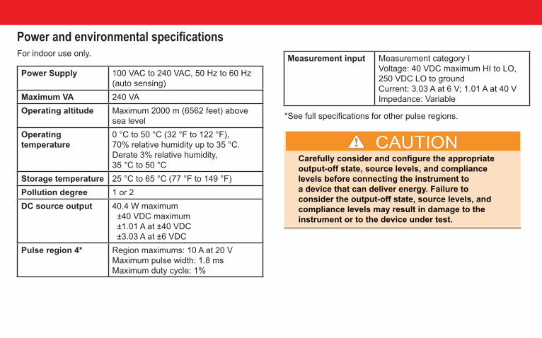
*See full specifications for other pulse regions.
Carefully consider and configure the appropriate output-off state, source levels, and compliance levels before connecting the instrument to a device that can deliver energy. Failure to consider the output-off state, source levels, and compliance levels may result in damage to the instrument or to the device under test.
Carefully consider and configure the appropriate output-off state, source levels, and compliance levels before connecting the instrument to a device that can deliver energy. Failure to consider the output-off state, source levels, and compliance levels may result in damage to the instrument or to the device under test.
Power and environmental specifications For indoor use only.
Power Supply 100 VAC to 240 VAC, 50 Hz to 60 Hz (auto sensing)
Maximum VA 240 VAOperating altitude Maximum 2000 m (6562 feet) above
sea levelOperating temperature
0 °C to 50 °C (32 °F to 122 °F), 70% relative humidity up to 35 °C. Derate 3% relative humidity, 35 °C to 50 °C
Storage temperature 25 °C to 65 °C (77 °F to 149 °F)Pollution degree 1 or 2DC source output 40.4 W maximum
±40 VDC maximum ±1.01 A at ±40 VDC ±3.03 A at ±6 VDC
Pulse region 4* Region maximums: 10 A at 20 VMaximum pulse width: 1.8 msMaximum duty cycle: 1%
Measurement input Measurement category IVoltage: 40 VDC maximum HI to LO, 250 VDC LO to groundCurrent: 3.03 A at 6 V; 1.01 A at 40 VImpedance: Variable

Safety Introduction
Software for the Series 2600B instruments is available for download from the Keithley web page. Go to www.tek.com/keithley and search for the specific software you need.
• Test Script Builder (TSB) Integrated Development Environment: Provides an environment to develop a test program and ability to load the test program onto the instrument.
• IVI instrument driver for National Instruments LabVIEW™ and related release notes.
• J2SE™ Runtime Environment.
• Keithley I/O layer and release notes
Introduction The Keithley Instruments Series 2600B System SourceMeter® Instruments are medium-power source-measure units (SMUs) that simplify test processes by combining source and measure capabilities in a single instrument. A Series 2600B SourceMeter Instrument is a scalable, high-throughput, cost-effective solution for precision DC, pulse, and low-frequency AC source-measure testing.
Complete documentation for the Series 2600B instruments is available for download on the Keithley web page. Go to www.tek.com/keithley and search for Series 2600B manual.
The Series 2600B documentation includes:• Quick Start Guide: Provides unpacking instructions,
describes basic connections, and reviews basic operation information.
• Reference Manual: Provides comprehensive information about the instrument’s features, operation, optimization, maintenance, troubleshooting, and programming commands
Safety Introduction Unpack Connect Test FAQsNext Steps
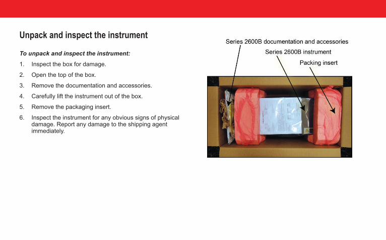
Unpack and inspect the instrument
To unpack and inspect the instrument:
1. Inspect the box for damage.
2. Open the top of the box.
3. Remove the documentation and accessories.
4. Carefully lift the instrument out of the box.
5. Remove the packaging insert.
6. Inspect the instrument for any obvious signs of physical damage. Report any damage to the shipping agent immediately.
Safety Introduction
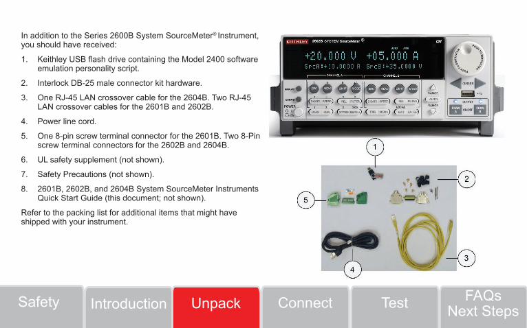
In addition to the Series 2600B System SourceMeter® Instrument, you should have received:
1. Keithley USB flash drive containing the Model 2400 software emulation personality script.
2. Interlock DB-25 male connector kit hardware.
3. One RJ-45 LAN crossover cable for the 2604B. Two RJ-45 LAN crossover cables for the 2601B and 2602B.
4. Power line cord.
5. One 8-pin screw terminal connector for the 2601B. Two 8-Pin screw terminal connectors for the 2602B and 2604B.
6. UL safety supplement (not shown).
7. Safety Precautions (not shown).
8. 2601B, 2602B, and 2604B System SourceMeter Instruments Quick Start Guide (this document; not shown).
Refer to the packing list for additional items that might have shipped with your instrument.
TestConnectSafety FAQsNext StepsIntroduction Unpack
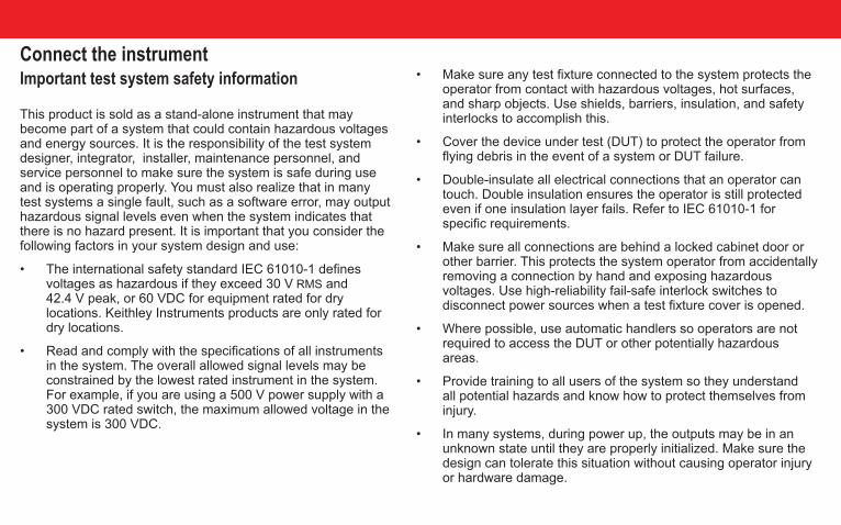
• Make sure any test fixture connected to the system protects the operator from contact with hazardous voltages, hot surfaces, and sharp objects. Use shields, barriers, insulation, and safety interlocks to accomplish this.
• Cover the device under test (DUT) to protect the operator from flying debris in the event of a system or DUT failure.
• Double-insulate all electrical connections that an operator can touch. Double insulation ensures the operator is still protected even if one insulation layer fails. Refer to IEC 61010-1 for specific requirements.
• Make sure all connections are behind a locked cabinet door or other barrier. This protects the system operator from accidentally removing a connection by hand and exposing hazardous voltages. Use high-reliability fail-safe interlock switches to disconnect power sources when a test fixture cover is opened.
• Where possible, use automatic handlers so operators are not required to access the DUT or other potentially hazardous areas.
• Provide training to all users of the system so they understand all potential hazards and know how to protect themselves from injury.
• In many systems, during power up, the outputs may be in an unknown state until they are properly initialized. Make sure the design can tolerate this situation without causing operator injury or hardware damage.
Connect the instrumentImportant test system safety information
This product is sold as a stand-alone instrument that may become part of a system that could contain hazardous voltages and energy sources. It is the responsibility of the test system designer, integrator, installer, maintenance personnel, and service personnel to make sure the system is safe during use and is operating properly. You must also realize that in many test systems a single fault, such as a software error, may output hazardous signal levels even when the system indicates that there is no hazard present. It is important that you consider the following factors in your system design and use:
• The international safety standard IEC 61010-1 defines voltages as hazardous if they exceed 30 V RMS and 42.4 V peak, or 60 VDC for equipment rated for dry locations. Keithley Instruments products are only rated for dry locations.
• Read and comply with the specifications of all instruments in the system. The overall allowed signal levels may be constrained by the lowest rated instrument in the system. For example, if you are using a 500 V power supply with a 300 VDC rated switch, the maximum allowed voltage in the system is 300 VDC.
Safety Introduction
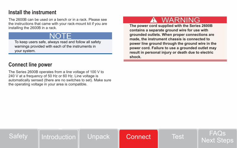
Install the instrumentThe 2600B can be used on a bench or in a rack. Please see the instructions that came with your rack-mount kit if you are installing the 2600B in a rack.
Connect line powerThe Series 2600B operates from a line voltage of 100 V to 240 V at a frequency of 50 Hz or 60 Hz. Line voltage is automatically sensed (there are no switches to set). Make sure the operating voltage in your area is compatible.
To keep users safe, always read and follow all safety warnings provided with each of the instruments in your system.
The power cord supplied with the Series 2600B contains a separate ground wire for use with grounded outlets. When proper connections are made, the instrument chassis is connected to power line ground through the ground wire in the power cord. Failure to use a grounded outlet may result in personal injury or death due to electric shock.
TestUnpackSafety FAQsNext StepsIntroduction Connect
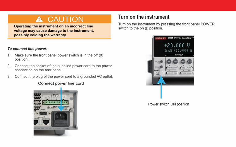
To connect line power:
1. Make sure the front panel power switch is in the off (0) position.
2. Connect the socket of the supplied power cord to the power connection on the rear panel.
3. Connect the plug of the power cord to a grounded AC outlet.
Operating the instrument on an incorrect line voltage may cause damage to the instrument, possibly voiding the warranty.
Turn on the instrumentTurn on the instrument by pressing the front panel POWER switch to the on (|) position.
Safety Introduction
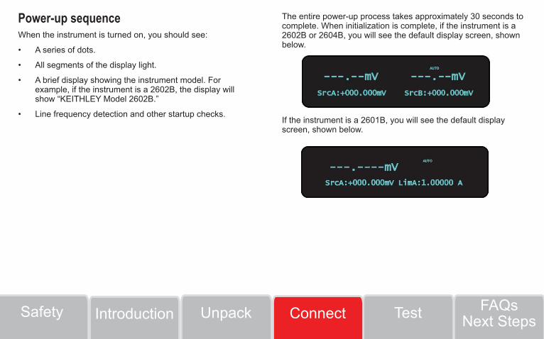
Power-up sequenceWhen the instrument is turned on, you should see:
• A series of dots.
• All segments of the display light.
• A brief display showing the instrument model. For example, if the instrument is a 2602B, the display will show “KEITHLEY Model 2602B.”
• Line frequency detection and other startup checks.
The entire power-up process takes approximately 30 seconds to complete. When initialization is complete, if the instrument is a 2602B or 2604B, you will see the default display screen, shown below.
If the instrument is a 2601B, you will see the default display screen, shown below.
TestUnpackSafety FAQsNext StepsIntroduction Connect

Test the instrumentThe following test verifies basic operation of the 2601B, 2602B, and 2604B. In this test, you will use the front-panel controls shown below to source voltage and measure the voltage output.
You do not need to connect a device under test (DUT) for this test.
Step 1: Set source function, range, and level
1. Press the SRC key. You will see a blinking character in the SrcA value field. Confirm that mV is displayed; if not, press the SRC key again.
2. While that character is still blinking, press the up or down RANGE keys until 40 V is displayed.
If the instrument has two channels (2602B or 2604B) and is in dual-channel display mode, press the DISPLAY button once to show only the settings for SMU channel A.
Safety Introduction
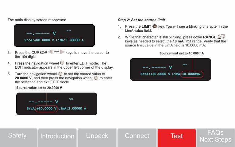
The main display screen reappears:
3. Press the CURSOR keys to move the cursor to the 10s digit.
4. Press the navigation wheel to enter EDIT mode. The EDIT indicator appears in the upper left corner of the display.
5. Turn the navigation wheel to set the source value to 20.0000 V, and then press the navigation wheel to enter the selection and exit EDIT mode.
Step 2: Set the source limit
1. Press the LIMIT key. You will see a blinking character in the LimA value field.
2. While that character is still blinking, press down RANGE keys as needed to select the 10 mA limit range. Verify that the source limit value in the LimA field is 10.0000 mA.
ConnectUnpackSafety FAQsNext StepsIntroduction Test
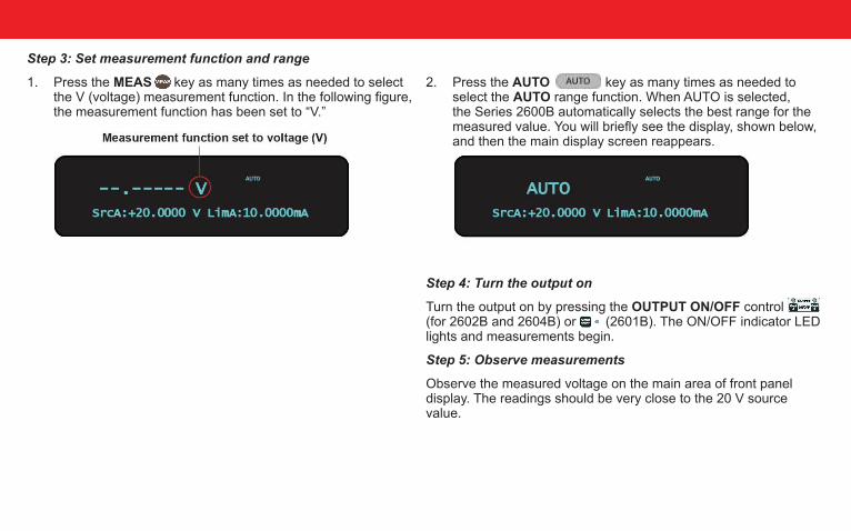
Step 3: Set measurement function and range
1. Press the MEAS key as many times as needed to select the V (voltage) measurement function. In the following figure, the measurement function has been set to “V.”
2. Press the AUTO key as many times as needed to select the AUTO range function. When AUTO is selected, the Series 2600B automatically selects the best range for the measured value. You will briefly see the display, shown below, and then the main display screen reappears.
Step 4: Turn the output on
Turn the output on by pressing the OUTPUT ON/OFF control (for 2602B and 2604B) or (2601B). The ON/OFF indicator LED lights and measurements begin.
Step 5: Observe measurements
Observe the measured voltage on the main area of front panel display. The readings should be very close to the 20 V source value.
Step 6: Turn the output off
When you finish making measurements, turn the output off by pressing the OUTPUT ON/OFF control or control. The output indicator LED turns off.
For a basic understanding of the of the Series 2600B functionality, we strongly recommend that first-time users become familiar with the Series 2600B Reference Manual.
These steps confirm basic functionality of your 2601B, 2602B, or 2604B instrument. Turn the instrument power OFF now.
ConnectUnpackSafety FAQsNext StepsIntroduction Test
FAQs
What should I do if I see an error message when I turn the instrument on?
If an error message is displayed, press the EXIT (LOCAL) key. The Series 2600B will return to the default display screen. For detailed information about error messages, see “Errors and status messages” in the Series 2600B Reference Manual.
How do I use the included USB flash drive?
The USB flash drive included with the Series 2600B can be used to load test scripts onto the instrument from the front panel. The included USB flash drive contains a copy of the 2400 personality script, which allows the Series 2600B instrument to accept 2400 SCPI commands. For more information about loading and running the 2400 personality script, see “Model 2400 emulation” in the Series 2600B Reference Manual.
What do I do if I lost or formatted the included USB flash drive? How can I get another copy of the 2400 personality script?
If you lose or format the USB drive or delete the 2400 personality script, you can download the latest version from the Keithley Instruments website. Go to www.tek.com/keithley and search for TSP Script for Series 2600B SMUs to Emulate Model 2400 SMUs.

Safety Introduction
Next steps
The Series 2600B Reference Manual
Refer to the Series 2600B Reference Manual for detailed information about all features of the instrument.
Keithley Instruments website
See: www.tek.com/keithley for support and additional information about the instrument.
ConnectUnpackSafety TestIntroduction FAQsNext Steps

Contact Information: Australia* 1 800 709 465Austria 00800 2255 4835
Balkans, Israel, South Africa and other ISE Countries +41 52 675 3777Belgium* 00800 2255 4835
Brazil +55 (11) 3759 7627Canada 1 800 833 9200
Central East Europe / Baltics +41 52 675 3777Central Europe / Greece +41 52 675 3777
Denmark +45 80 88 1401Finland +41 52 675 3777France* 00800 2255 4835
Germany* 00800 2255 4835Hong Kong 400 820 5835
India 000 800 650 1835Indonesia 007 803 601 5249
Italy 00800 2255 4835Japan 81 (3) 6714 3010
Luxembourg +41 52 675 3777Malaysia 1 800 22 55835
Mexico, Central/South America and Caribbean 52 (55) 56 04 50 90Middle East, Asia, and North Africa +41 52 675 3777
The Netherlands* 00800 2255 4835New Zealand 0800 800 238
Norway 800 16098People’s Republic of China 400 820 5835
Philippines 1 800 1601 0077Poland +41 52 675 3777
Portugal 80 08 12370Republic of Korea +82 2 6917 5000
Russia / CIS +7 (495) 6647564Singapore 800 6011 473
South Africa +41 52 675 3777Spain* 00800 2255 4835
Sweden* 00800 2255 4835Switzerland* 00800 2255 4835
Taiwan 886 (2) 2656 6688Thailand 1 800 011 931
United Kingdom / Ireland* 00800 2255 4835USA 1 800 833 9200
Vietnam 12060128
Find more valuable resources at TEK.COMCopyright © 2017, Tektronix. All rights reserved. Tektronix products are covered by U.S. and foreign patents, issued and pending. Information in this publication supersedes that in all previously published material. Specification and price change privileges reserved. TEKTRONIX and TEK are registered trademarks of Tektronix, Inc. All other trade names referenced are the service marks, trademarks or registered trademarks of their respective companies.
* European toll-free number. If not accessible, call: +41 52 675 3777
A Tektronix Company
*P2602B-903-01C*
2602B-903-01 Rev. C / April 2017