Modelling underground mines for rock stability … · stability assessment using boundary elements:...
10
Modelling underground mines for rock stability assessment using boundary elements: a new approach for large scale problems R. Adey & A. Calaon Abstract The Boundary Element Method has been applied to calculate stress distribution and stability of underground mines for disposal of chemical waste. A case similar to the Stripa mine in Sweden has been considered. The rock mass was granite, with major fracture zones represented by three families of planes mutually orthogonal and 100 meters distant from each other. The pre and post processor GiD [3] and the Boundary Element software BEASY [2] have been used for model preparation, solution and result post processing. A modelling technology has been developed to enable the investigation of stability in the presence of a large number of fracture zones while at the same time determining the detailed stress near the mine. Results for stress and stability of the rock are presented here and discussed. 1 Introduction This work was performed under the LowRiskDT project [4] which aimed to investigate the suitability of abandoned mines for the storage of toxic waste. A major part of the project was the use computational models to predict the performance of proposed repositories for disposal of chemical waste. The project identified a number of mine types representative of those found in the EU for investigation. The mines were assessed for their stability and isolation capacity (flow and transport) In this paper some results are presented showing the computations performed to determine the rock stability through stress analysis of reference mine repositories which could provide safe and permanent isolation of hazardous waste. Waste Management and the Environment II, V. Popov, H. Itoh, C.A. Brebbia & S. Kungolos (Editors) © 2004 WIT Press, www.witpress.com, ISBN 1-85312-738-8 Southampton, UK Computational Mechanics BEASY, Ashurst Lodge, Ashurst,
Transcript of Modelling underground mines for rock stability … · stability assessment using boundary elements:...
Modelling underground mines for rock stability assessment using boundary elements: a new approach for large scale problems
R. Adey & A. Calaon
Abstract
The Boundary Element Method has been applied to calculate stress distribution and stability of underground mines for disposal of chemical waste. A case similar to the Stripa mine in Sweden has been considered. The rock mass was granite, with major fracture zones represented by three families of planes mutually orthogonal and 100 meters distant from each other. The pre and post processor GiD [3] and the Boundary Element software BEASY [2] have been used for model preparation, solution and result post processing. A modelling technology has been developed to enable the investigation of stability in the presence of a large number of fracture zones while at the same time determining the detailed stress near the mine. Results for stress and stability of the rock are presented here and discussed.
1 Introduction
This work was performed under the LowRiskDT project [4] which aimed to investigate the suitability of abandoned mines for the storage of toxic waste. A major part of the project was the use computational models to predict the performance of proposed repositories for disposal of chemical waste. The project identified a number of mine types representative of those found in the EU for investigation. The mines were assessed for their stability and isolation capacity (flow and transport) In this paper some results are presented showing the computations performed to determine the rock stability through stress analysis of reference mine repositories which could provide safe and permanent isolation of hazardous waste.
Waste Management and the Environment II, V. Popov, H. Itoh, C.A. Brebbia & S. Kungolos (Editors)© 2004 WIT Press, www.witpress.com, ISBN 1-85312-738-8
Southampton, UK Computational Mechanics BEASY, Ashurst Lodge, Ashurst,

The models were based on the Boundary Element Method (BEM). BEM has a number of advantages over the Finite Element Method (FEM) for modelling media such as rock, since only the fracture zones are required to be described with elements. The homogeneous media between the fracture zones can be modelled as blocks of material whose boundary is described by the elements on the fracture zones. The presence of different material properties, the geometry of the Engineering disturbed zone (EDZ), and the extensive fractured media make it necessary to have an efficient tool to generate many “zones” in a single BEM model. (Note: zones are regions of the model with different material properties) A specialized geometry and input file generator was found in the GiD software. Since GiD is a general tool pre- post processor, mesher and solid modeller, an extensive customisation has been necessary to make it able to deal with BEM calculations and with the very special needs of underground modelling, often very different from the ones in mechanics. Many facilities have been introduced in GiD and a complete problem-type (as the set of customizing files is called inside the GiD environment) has been programmed. One of the major advantages of using a solid modeller as pre-processor is the possibility to have the critical information (in multi-zonal BEM) about which volume (zone) a surface belongs to. The access to this knowledge (through Tcl functions reading the GiD database) permitted the efficient production of model files with hundreds of zones which otherwise would have been extremely time consuming and costly. Complicated geometries are also possible with the 3D modelling capabilities of GiD. Although some feature not present in GiD would help significantly in underground modelling (and some of them will probably be included in the next release) all the geometries of the present project have been built with GiD only. Some menus and toolbars have been created in the problem-type to speed the model creation and imposition of boundary conditions.
2 Mohr-Coulomb criterion
The modelling of the rock structure provides complete information on the stresses and deformation. However, in order to assess the stability, a criterion was selected to assess the mine performance. In rock mechanics the most used brittle failure criterion is the Mohr-Coulomb one so this was used [1]. (Other possible criteria for rock stability comprise the Hoek-Brown criterion, and its generalized form, but they haven’t been considered in the project.) It establishes a limit for the difference between maximum and minimum principal stresses, depending on the maximum itself, often called “confining stress”. Here the equation representing the critical state used (mechanical convention): ( )1 3' 'cm kσ σ σ= − + (1)
In equation (1) 1'σ is the minimum principal stress (eigen-value of the stress
tensor), and 3'σ is the maximum. K represents a multiplication factor for the minimum stress and is equal to:
182 Waste Management and the Environment II
Waste Management and the Environment II, V. Popov, H. Itoh, C.A. Brebbia & S. Kungolos (Editors)© 2004 WIT Press, www.witpress.com, ISBN 1-85312-738-8

1 sin1 sin
kφφ
+= −
(2)
and cmσ is the uniaxial compressive strength:
02 cos1 sincm
c φσ
φ=
− (3)
The field visualized has then a 0 value everywhere apart from the areas where the failure criterion is not respected. There the value of the field changes to 1.
3 Sub modelling
For any numerical model any small feature where the solution is rapidly varying, embedded in a much bigger and “smooth” part, presents a modelling challenge. In fact small features need small elements on them, and even smaller if the derivative of the result itself is of interest (possible local failure). On the other hand a big part of the model doesn’t need a particularly fine mesh since there is very little variation there. In order to be able to handle the geometry of tunnel and room, each of them crossed by a vertical fracture zone, the EDZ zone is divided in sub-zones and the big “cubes” of rock in the Granite case, a sub-modelling technique was used. The new method uses a technique, which can be adopted not only for this case, but also in the general interaction between FEM and BEM models.
4 Some experiments to determine the required model details
In order to have an idea of the extent of the critical coulomb zone and of the mesh dimension necessary to represent it with sufficient precision, a number of simplified models were created. They represent a section of the rock with a tunnel in it, split by a fracture zone. Models with and without EDZ were assessed, at the normal tectonic pressure of 20 MPa and at an increased one (not shown in here). The tectonic pressure was applied indirectly to the model, by forcing a compression displacement of the side walls of the model, as in the “big” case with sub-modelling. Since the value of the displacements to be used could not be predicted in advance, two cases were considered and a linear interpolation used to obtain the required values for a third model to confirm the result. The first experiment was performed without the EDZ zones and with a tectonic pressure of 20 MPa in all horizontal directions. This experiment showed that for the Mohr-Coulomb criterion all the tunnel, walls, ceiling and floor and their surrounding are instable (see Figure 1). The principal reason is that the so-called “confining stress” cannot reach the walls. A small tension stress appears in the rock and endangers the local stability. In the present case not only the sides (where the tension develops) of the tunnel are unstable, but the ceiling and the floor as well (on the floor the max principal stress in practically 0 everywhere). This experiment shows also that the necessary mesh resolution around the whole tunnel should be not less than the one used in the example.
Waste Management and the Environment II 183
Waste Management and the Environment II, V. Popov, H. Itoh, C.A. Brebbia & S. Kungolos (Editors)© 2004 WIT Press, www.witpress.com, ISBN 1-85312-738-8

Figure 1: Mohr-Coulomb criterion result near the crossing fracture zone in the first model without EDZ.
A second experiment was performed using the same geometry, but with a 1 meter deep EDZ divided in sub-zones. The new mesh is shown in Figure 2.
Figure 2: Mesh of the second model with EDZ on the left and Mohr-Coulomb result on the right.
The Mohr-Coulomb result is shown in Figure 2; it is practically the same of the case without EDZ and the shape of the failure area in the fracture zone is also identical. A comparison can be made between Figure 1 and Figure 2. If we look at the max stress (not pictured here) in the two cases, although it has the same pattern, it is slightly higher in the second, due to the presence of a minimal support of the EDZ internal layer. The minimum (maximum for geological conventions) is for engineering purposes practically identical in the two cases. This explains also why the extension of the “Mohr-Coulomb failure zone” is
184 Waste Management and the Environment II
Waste Management and the Environment II, V. Popov, H. Itoh, C.A. Brebbia & S. Kungolos (Editors)© 2004 WIT Press, www.witpress.com, ISBN 1-85312-738-8

identical for the two cases, and is the principal reason why we decided that the result of models without EDZ, can be taken as valid and representative for the same geometry and BC but with EDZ. So we assumed: in practice the presence of the EDZ doesn’t change the stability problem.
5 Full scale model
The rock mass surrounding room and tunnel was modelled to a depth 800 meters below the ground level (see Figure 3). A square area of 600 by 600 meters represents a horizontal cross section of a parallelogram enclosing the whole model. The rock mass is cut by 3 ortho-normal fracture zone families, 2 vertical and 1 horizontal. For all of them the distance between the discontinuity planes is 100 meters, so the rock matrix around room and tunnel is made up by a 3 dimensional array of cubes with a 100 meters long edge. A room and a tunnel, both empty, are located inside three blocks in the “middle” of the model, with the room ceiling depth at 425 meters. Both room and tunnel are crossed by only one vertical fracture zone. The room dimensions are: Cross section: 50 [m] x 50 [m] Length: 100 [m] The tunnel dimensions are: Cross section: 5 [m] x 5 [m] Length: 150 [m] The tunnel is parallel to the length of the room and departs from it starting from the centre of a bottom edge. Without sub-modelling the number of dof in the model would be too large to be solved in a reasonable time. This conclusion still applied when attempts were made to limit the mesh refinement using techniques like the transition mesh for passing from a coarse to a refined one. Therefore the sub-modelling strategy was chosen, and two different models prepared from the large model.
5.1 Global (outer) model
An “outer” model was created starting from the complete one where only the “rock cubes” where represented. The model consists of 288 volumes and is shown in Figure 3. The bottom surface has been constrained vertically, and the sides moved inward, squeezing the rock blocks. To have an equivalent stress of about 20 MPa on the sides, a normal displacement of few centimetres was applied to the eternal “walls” of the model.
Waste Management and the Environment II 185
Waste Management and the Environment II, V. Popov, H. Itoh, C.A. Brebbia & S. Kungolos (Editors)© 2004 WIT Press, www.witpress.com, ISBN 1-85312-738-8

Figure 3: Scheme of the complete model for granite.
Figure 4: Outer model with refined mesh in the part surrounding the sub-model.
5.2 Sub model
The sub-model, sharing its external surface with the “outer” one, is depicted in Figure 5. Since the experiments previously described showed that the presence of the EDZ wouldn’t sensibly change the stability conditions, a simplified model was prepared in which no EDZ was modelled, assuming so a worst case.
312.5
The surfaces with triangles represent thetransition mesh, between the externalcoarse one and the internal, boundary ofthe sub-model.
425 m
186 Waste Management and the Environment II
Waste Management and the Environment II, V. Popov, H. Itoh, C.A. Brebbia & S. Kungolos (Editors)© 2004 WIT Press, www.witpress.com, ISBN 1-85312-738-8

The displacement boundary conditions have been calculated from the “big” model and introduced in the data file. This model was solved successfully.
Figure 5: Geometry and mesh of the sub-model.
The material properties used for all the models are: E = 50 GPa; ν = 0.3; c0 = 1 MPa, φ0 = 35°.
6 Results
6.1 Global model
The results of the global model are very simple to interpret, since the whole geometry shrinks horizontally, and, due to the confining pressure, it raises up slightly in the upper part (orogenenis). A lateral compressive stress linearly increasing with the depth results form the calculation, and its intensity varies form about 14.3 MPa near the surface, to about 23.4 MPa at the bottom.
6.2 Sub-model
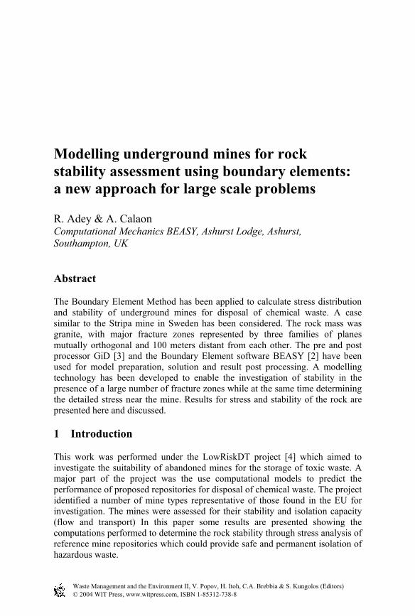
The displacement of the outer model on the surface shared with the sub-model was applied as boundary conditions to the sub-model without EDZ, assuming the presence of room and tunnel does not have any influence on the outer model solution. The software is designed to automatically interpolate and so map the results on one model to provide the loads and boundary conditions for the other using a radial basis function approximation to ensure accuracy. This makes the detailed study of regions of special interest easy to perform. The model was solved and the stress results are presented in the following figures. In Figure 6 the principal min stresses on the tunnel far from the room are shown. As previously seen in the experimental models, a light tension (max principal stress not pictured) develops along the walls of the tunnel and the min principal stress is maximal there, so limiting the effect of the tension for the Mohr-Coulomb failure.
Waste Management and the Environment II 187
Waste Management and the Environment II, V. Popov, H. Itoh, C.A. Brebbia & S. Kungolos (Editors)© 2004 WIT Press, www.witpress.com, ISBN 1-85312-738-8
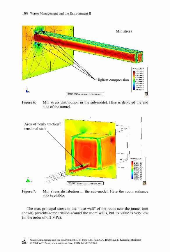
Figure 6: Min stress distribution in the sub-model. Here is depicted the end side of the tunnel.
Figure 7: Min stress distribution in the sub-model. Here the room entrance side is visible.
The max principal stress in the “face wall” of the room near the tunnel (not shown) presents some tension around the room walls, but its value is very low (in the order of 0.2 MPa).
Min stress
Highest compression
Area of “only traction”tensional state
188 Waste Management and the Environment II
Waste Management and the Environment II, V. Popov, H. Itoh, C.A. Brebbia & S. Kungolos (Editors)© 2004 WIT Press, www.witpress.com, ISBN 1-85312-738-8
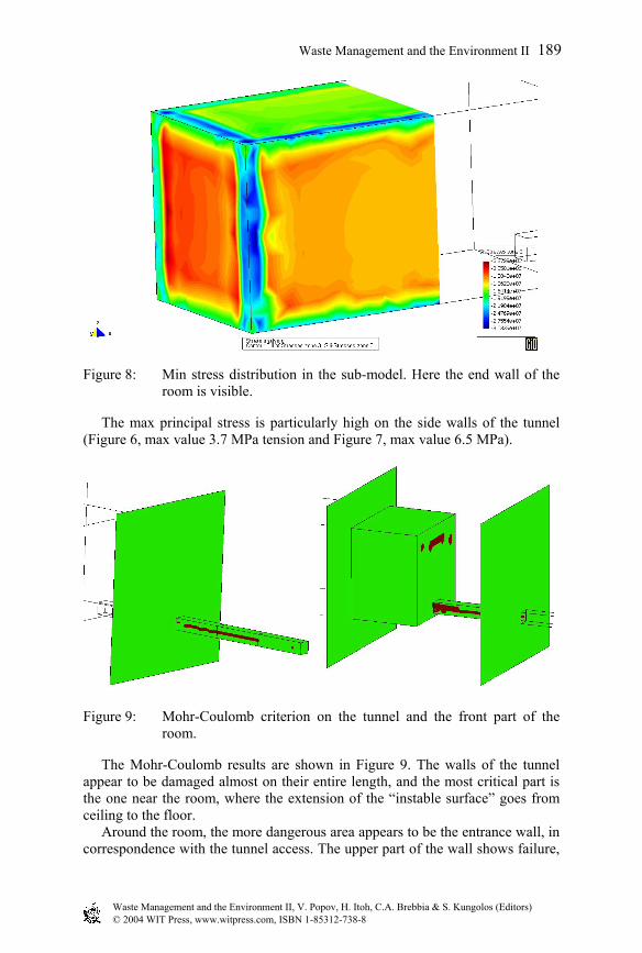
Figure 8: Min stress distribution in the sub-model. Here the end wall of the room is visible.
The max principal stress is particularly high on the side walls of the tunnel (Figure 6, max value 3.7 MPa tension and Figure 7, max value 6.5 MPa).
Figure 9: Mohr-Coulomb criterion on the tunnel and the front part of the room.
The Mohr-Coulomb results are shown in Figure 9. The walls of the tunnel appear to be damaged almost on their entire length, and the most critical part is the one near the room, where the extension of the “instable surface” goes from ceiling to the floor. Around the room, the more dangerous area appears to be the entrance wall, in correspondence with the tunnel access. The upper part of the wall shows failure,
Waste Management and the Environment II 189
Waste Management and the Environment II, V. Popov, H. Itoh, C.A. Brebbia & S. Kungolos (Editors)© 2004 WIT Press, www.witpress.com, ISBN 1-85312-738-8

and would probably be the first to cause dangerous rock fall. The rest of the room appears to be safe, but another calculation not shown here, with an increased tectonic stress (30 MPa), shows it completely collapsing. The results suggest that the state calculated with 20 MPa tectonic stress is very near the load at which the instability propagates form the front wall to the rest of the room walls and ceiling.
7 Conclusions
Tools have been developed to investigate the stability of potential mine repository sites. Combining the facilities of BEASY for modelling fractured structures and extensive customization of the GiD program, a convenient tool has been developed to model the stability of mine repository sites in highly fractured materials like crystalline rock. One reference mine has been investigated. It was a mine in a crystalline rock with a fractured matrix (100 m distance between the fracture zones). Experiments on small detailed models showed that there was no influence of practical significance with the presence or absence of the EDZ. Therefore it was concluded that there is no need in this case to model the EDZ when assessing the stability. A sub modelling approach was developed to map results and data from the large “regional” based model to the smaller but much more detailed local model. The big “regional” model was analysed first with the major tectonic boundary conditions applied. The results were then transformed to boundary conditions for the sub model, which was solved to reveal the detailed stress and deformation in the immediate vicinity of the mine. The stability analysis, performed using the Mohr-Coulomb failure criterion shows that the tunnel and some part of the room are unstable. A second model with increased tectonic forces 30MPa indicated substantial instability with the room totally damaged. With this configuration the mine at tectonic loads of 20MPa or more would require strengthening.
Acknowledgement
This work was performed as part of the LowRiskDT project partly financed by the EU Framework 5 Programme.
References
[1] Hoek, E., P.K.Kaiser & W.F.Bawden: Support of underground excavations in hard rock, A.A.Balkema Publishers.
[2] Computational Mechanics BEASY. Webpage: www.beasy.com. [3] GiD resources. Website: http://gid.cimne.upc.es. [4] LowRisk Project webpage: http://www.beasy.com/projects/lowriskdt/
lowrisk_home.html.
190 Waste Management and the Environment II
Waste Management and the Environment II, V. Popov, H. Itoh, C.A. Brebbia & S. Kungolos (Editors)© 2004 WIT Press, www.witpress.com, ISBN 1-85312-738-8