MODELLING THE UNBALANCED MAGNETIC PULL...
72
TKK Dissertations 93 Espoo 2007 MODELLING THE UNBALANCED MAGNETIC PULL IN ECCENTRIC-ROTOR ELECTRICAL MACHINES WITH PARALLEL WINDINGS Doctoral Dissertation Helsinki University of Technology Department of Electrical and Communications Engineering Laboratory of Electromechanics Andrej Burakov
Transcript of MODELLING THE UNBALANCED MAGNETIC PULL...

TKK Dissertations 93Espoo 2007
MODELLING THE UNBALANCED MAGNETIC PULL IN ECCENTRIC-ROTOR ELECTRICAL MACHINES WITH PARALLEL WINDINGSDoctoral Dissertation
Helsinki University of TechnologyDepartment of Electrical and Communications EngineeringLaboratory of Electromechanics
Andrej Burakov
TKK Dissertations 93Espoo 2007
Andrej Burakov
Dissertation for the degree of Doctor of Science in Technology to be presented with due permission of the Department of Electrical and Communications Engineering for public examination and debate in Auditorium S1 at Helsinki University of Technology (Espoo, Finland) on the 25th of October, 2007, at 12 noon.
Helsinki University of TechnologyDepartment of Electrical and Communications EngineeringLaboratory of Electromechanics
Teknillinen korkeakouluSähkö- ja tietoliikennetekniikan osastoSähkömekaniikan Laboratorio
MODELLING THE UNBALANCED MAGNETIC PULL IN ECCENTRIC-ROTOR ELECTRICAL MACHINES WITH PARALLEL WINDINGSDoctoral Dissertation

Distribution:Helsinki University of TechnologyDepartment of Electrical and Communications EngineeringLaboratory of ElectromechanicsP.O. Box 3000FI - 02015 TKKFINLANDURL: http://www.tkk.fi/Units/Electromechanics/Tel. +358-9-451 2381Fax +358-9-451 2991E-mail: [email protected]
© 2007 Andrej Burakov
ISBN 978-951-22-9005-5ISBN 978-951-22-9006-2 (PDF)ISSN 1795-2239ISSN 1795-4584 (PDF) URL: http://lib.tkk.fi/Diss/2007/isbn9789512290062/
TKK-DISS-2358
Picaset OyHelsinki 2007

AB
ABSTRACT OF DOCTORAL DISSERTATION HELSINKI UNIVERSITY OF TECHNOLOGY P.O. BOX 1000, FI-02015 TKK http://www.tkk.fi
Author Andrej Burakov
Name of the dissertation Modelling the unbalanced magnetic pull in eccentric-rotor electrical machines with parallel windings
Manuscript submitted 08.06.2007 Manuscript revised 07.10.2007
Date of the defence 25.10.2007
Monograph Article dissertation (summary + original articles)
Department Electrical and Communications Engineering Laboratory Electromechanics Field of research Electrical machines Opponent(s) Dr. David Dorrell Supervisor Prof. Antero Arkkio Instructor ---
Abstract This research work is focused on developing simple parametric models of the unbalanced magnetic pull produced in eccentric-rotor electrical machines. The influence of currents circulating in the parallel paths of the stator winding on the unbalanced magnetic pull is given the main attention. The interaction between these currents and those circulating in the rotor cage/damper winding is also considered. First, a parametric force model for an eccentric-rotor salient-pole synchronous machine is developed. The effects of the parallel stator windings are not considered in this model. Next, a low-order parametric force model is built for electrical machines equipped with parallel stator windings but operating without the rotor cage/damper winding. This force model is applicable to salient-pole synchronous machines as well as to induction motors. And finally, a special force model is developed for electrical machines furnished with parallel paths both in the rotor and stator windings. This model accounts for the equalising currents circulating in the rotor and stator windings and also for the interaction between these currents. This third force model can be applied to a salient-pole synchronous machine and to an induction machine. The parameters of the force models are estimated from the results of numerical simulations applying a soft-computing-based estimation program. All the developed force models with the estimated parameters demonstrate a very good performance in a wide whirling frequency range. The effects of parallel paths in the rotor and stator windings on the unbalanced magnetic pull are investigated numerically. The acquired results reveal that the total unbalanced magnetic pull and its constituents related to the fundamental magnetic field and slotting are strongly affected by the presence of parallel paths in the stator winding. However, unlike the rotor cage, parallel stator windings may instigate anisotropy in the unbalanced magnetic pull. In such cases, the results of the numerical impulse response test may differ significantly from the conventional calculation results. It is also shown that, despite the fact that the number of parallel paths in the stator is often substantially lower than the number of parallel paths in the rotor, parallel stator windings may still provide a more efficient UMP mitigation than the rotor cage/damper winding..
Keywords parallel windings, rotor eccentricity, unbalanced magnetic pull
ISBN (printed) 978-951-22-9005-5 ISSN (printed) 1795-2239
ISBN (pdf) 978-951-22-9006-2 ISSN (pdf) 1795-4584
Language English Number of pages 154 p.
Publisher Helsinki University of Technology, Laboratory of Electromechanics
Print distribution Helsinki University of Technology, Laboratory of Electromechanics
The dissertation can be read at http://lib.tkk.fi/Diss/2007/isbn9789512290062/

4
Preface
This research work was conducted in the Laboratory of Electromechanics at Helsinki University of Technology.
I gratefully acknowledge the invaluable help, guidance and support received throughout the whole course of this project from Professor Antero Arkkio. For discovering the potential in me and maintaining the fruitful and encouraging discussions, I owe my sincere gratitude to Professor Asko Niemenmaa (Head of the Laboratory) and Emeritus Professor Tapani Jokinen. I am thankful to Dr. Asmo Tenhunen and Dr. Timo Holopainen for sharing their profound experience and knowledge of electrical machines with me. I am much obliged to Mr. Ari Haavisto for his invaluable help and assistance in practical matters. I remain grateful to Mrs. Marika Schröder, who helped me in mastering the bureaucratic impediments. I am also greatly indebted to my colleagues and friends who made it possible to keep my spirits high all the way through my postgraduate studies.
It is impossible to overestimate the favourable stimulus I experienced sharing my life with Mr. Gábor Gyöngy. The steal-solid support, relentless encouragement and unsurpassed enthusiasm always showed by Mr. Vasil Denchev is also very much appreciated. Dr. Marian Dumitru Negrea is gratefully acknowledged for his thoughtful and attentive advice.
I would like to express heartfelt gratitude to my deceased grandparents Zinaida and Andrej Fitingovs for their invaluable contribution to developing my personality. My dearly-loved parents are thankfully acknowledged for their kindness, dedication and strong belief in me throughout all my life. I also owe great gratitude to my dearest brothers and sister.
For teaching me to conquer the most difficult challenges, I am genuinely obliged to my close friend, Mr. Aleksandr Miteniov “Mituxa”.
My deepest gratitude I reserve for my beloved wife Marija, for being a vital source of inspiration, encouragement and happiness. It is her patience, love and devotion that made it possible to successfully complete this Dissertation and I wholeheartedly dedicate it to her.
The continuous financial support from the Graduate School in Electrical Engineering is acknowledged gratefully. I also highly appreciate the financial aid granted by Emil Aaltosen Foundation.
Espoo, May 2007
Andrej Burakov

5
Content
Preface .............................................................................................................................................................. 4
Content ............................................................................................................................................................. 5
List of publications........................................................................................................................................... 6
List of symbols and abbreviations .................................................................................................................. 7 Symbols used and their SI units of measure.................................................................................................. 7 Abbreviations.............................................................................................................................................. 10
1 Introduction................................................................................................................................................. 11 1.1 Background of the study ....................................................................................................................... 11 1.2 Aim of the work .................................................................................................................................... 14 1.3 Scientific contribution of the work........................................................................................................ 14 1.4 Structure of the work............................................................................................................................. 15
2 Overview of the electromagnetic field and force calculation .................................................................. 22 2.1 Electromagnetic field computation ....................................................................................................... 22 2.2 Calculation of electromagnetic force .................................................................................................... 25 2.3 Literature review ................................................................................................................................... 31
2.3.1 Analytical methods ........................................................................................................................ 31 2.3.2 Numerical methods........................................................................................................................ 36 2.3.3 Combining the analytical and numerical methods ........................................................................ 40
2.4 Need for further research ...................................................................................................................... 41 2.5 Conclusions........................................................................................................................................... 42
3 Methods of analysis..................................................................................................................................... 44 3.1 Parametric force model ......................................................................................................................... 46 3.2 Parameter estimation............................................................................................................................. 48 3.3 Conclusions........................................................................................................................................... 48
4 Discussion of the results.............................................................................................................................. 49 4.1 Verification of the force models............................................................................................................ 49 4.2 Influence of parallel stator windings on the UMP constituents............................................................. 53 4.3 Other issues related to the parallel stator windings ............................................................................... 54 4.4 Parallel stator windings vs. rotor cage vs. parallel stator windings + rotor cage................................... 55 4.5 Conclusions........................................................................................................................................... 57
5 Summary ..................................................................................................................................................... 61
References....................................................................................................................................................... 62
Appendices...................................................................................................................................................... 71
6
List of publications
The thesis consists of an overview and the following publications:
P1. Burakov, A., Tenhunen, A., Arkkio, A. 2005. Applying Genetic Algorithms to
identify the parameters of a low-order force model for a salient-pole synchronous
machine with eccentric rotor. 8-th International Conference on Modeling and
Simulation of Electric Machines, Converters and Systems, April 17-20, 2005,
Hammamet, Tunisia, 5 p.
P2. Burakov, A., Arkkio, A. 2006. Low-order parametric force model for a salient-pole
synchronous machine with eccentric rotor. Electrical Engineering (Archiv fur
Elektrotechnik), Springer Berlin / Heidelberg, Vol. 89, No. 2, pp. 127-136.
P3. Burakov, A., Arkkio, A. 2006. Low-order parametric force model for eccentric-rotor
electrical machine with parallel connections in stator winding. IEE Proceedings,
Electric Power Applications, Vol. 153, Issue 4, pp. 592-600.
P4. Burakov, A., Arkkio, A. 2006. Validity of numerical impulse response test in
studying unbalanced magnetic pull in electrical machines with parallel stator
windings. Proceedings of XVII International Conference on Electrical Machines,
September 2-5, 2006, Chania, Crete Island, Greece, 5 p.
P5. Burakov, A., Arkkio, A. 2007. Low-order parametric force model for eccentric-rotor
electrical machine equipped with parallel stator windings and rotor cage. IET Electric
Power Applications, Vol. 1, Issue 4, pp. 532-542.
P6. Burakov, A., Arkkio, A. 2007. Mitigation of UMP components by the parallel stator
windings in eccentric-rotor electrical machines. The IEEE International Electric
Machines and Drives Conference (IEMDC 2007), May 3-5, 2007, Antalya, Turkey,
pp. 1638-1642.
P7 Burakov, A., Arkkio, A. 2007. Comparison of the unbalanced magnetic pull
mitigation by the parallel paths in the stator and rotor windings. IEEE Transactions
on Magnetics, in press.
7
List of symbols and abbreviations
Symbols used and their SI units of measure
Symbols in bold represent vector quantities, symbols in italic represent scalar quantities,
underlined quantities are complex-valued.
0’ rotor axis, [-]
A magnetic vector potential, [Wb/m]
1pA − , 1pA + force model parameters, [H]
B magnetic flux density, [T]
B total magnetic flux density, [T]
,1pB first constituent of the fundamental magnetic flux density component
caused by interaction of the fundamental MMF waves with constant
permeance term, [T]
,2pB second constituent of the fundamental magnetic flux density component
caused by interaction of the fundamental MMF waves with the first
Fourier series component of the air gap permeance related to rotor
saliency, [T]
nB magnetic flux density component normal to the surface, [T]
tB magnetic flux density component tangential to the surface, [T]
Bx magnetic flux density component in x-direction, [T]
By magnetic flux density component in y-direction, [T]
Bz magnetic flux density component in z-direction, [T]
D electric flux density, [C/m2]
rd outer diameter of the rotor, [m]
E electric field strength, [V/m]
ez unit-vector having z-direction, [-]
F electromagnetic force, [N]
eF unbalanced magnetic pull, [N]
Frad radial component of the unbalanced magnetic pull, [N]
Ftan tangential component of the unbalanced magnetic pull, [N]
xF electromagnetic force acting along the x-axis, [N]

8
f force density, [N/m3]
G Jacobian matrix
H magnetic field strength, [A/m]
J electric current density, [A/m2]
j imaginary unit, [-]
K frequency response function of the unbalanced magnetic pull, [N/m]
0k force model parameter, [N/m]
cr, 1pk ± dimensionless coupling factors for p±1 current harmonics in the rotor
winding, [-]
cs, 1pk ± dimensionless coupling factors for p±1 current harmonics in the stator
winding, [-]
L,r, 1pk ± coefficients defining the amounts of the corresponding magnetic flux
harmonics that pass through the damper winding from the sources other
than rotor currents, [H]
L,s, 1pk ± coefficients defining the amounts of the corresponding magnetic flux
harmonics that pass through the stator winding from the sources other
than stator currents, [H]
1pk − , 1pk + force model parameters, [N·rad/(m·s)]
r, 1pL ± inductances of the damper winding for p±1 magnetic flux density
harmonics, [H]
s, 1pL ± inductances of the stator winding for p±1 magnetic flux density
harmonics, [H]
el effective air-gap length, [m]
m wave number, [-]
n unit-vector normal to the surface, [-]
n wave number, [-]
r, 1pR ± resistances of the damper winding for p±1 current harmonics, [ Ω ]
s, 1pR ± resistances of the stator winding for p±1 current harmonics, [ Ω ]
r radius of the integration surface, [m]
rr inner radius of the air gap, [m]

9
sr outer radius of the air gap, [m]
S area of the integration surface, [m2]
Sag area of the air gap cross section, [m2]
r, 1,1pS ± , r, 1,2pS ± force model parameters, [ Ω /H]
s, 1,1pS ± , s, 1,2pS ± force model parameters, [ Ω /H]
s slip of the rotor, [-]
t unit-vector tangential to the surface, [-]
t time, [s]
V volume of the integration region, [m3]
'W magnetic co-energy, [J]
1pz − , 1pz + force model parameters, [rad/s]
0δ nominal air gap, [m]
eccδ rotor eccentricity, [m]
ε permittivity, [F/m]
φ reduced electric scalar potential, [V]
ϕ angular coordinate, [rad]
ecc.0ϕ initial phase angle of the rotor eccentricity, [rad]
pϕ phase angle between the fundamental magnetic flux density component
and the fundamental MMF vector of the field winding, [rad]
µ permeability, [H/m]
0µ permeability of free space, [H/m]
ν reluctivity, [m/H]
ρ electric charge density, [C/m3]
σ conductivity, [S/m]
τ Maxwell stress tensor, [N/m2]
1ω angular frequency of the supply voltage, [rad/s]
eccω whirling angular velocity, [rad/s]
reccω whirling angular velocity in rotor frame of reference, [rad/s]
Ω mechanical angular velocity of the rotor, [rad/s]

10
ψ magnetic scalar potential, [Wb·m]
*x complex conjugate of x
Abbreviations
2PP two parallel paths
4PP four parallel paths
FEA Finite Element Analysis
FEM Finite Element Method
FRF Frequency Response Function
GA Genetic Algorithms
MMF Magnetomotive Force
MWFA Modified Winding Function Approach
UMP Unbalanced Magnetic Pull
WFA Winding Function Approach

11
1 Introduction
1.1 Background of the study
In an electrical machine, both radial and tangential electromagnetic forces are
generated. However, if the motor is symmetrical with a perfectly centred rotor, the radial
electromagnetic forces are cancelled out and the tangential ones produce a rotating torque.
In practice, though, due to manufacturing tolerances, wear of bearings, rotor shaft bending
and many other factors, the rotor and stator axes hardly ever coincide and, thus, most of the
electrical motors operate with some degree of rotor eccentricity.
When the rotor axis does not coincide with the axis of the stator bore, the
imbalance of the electromagnetic forces acting between the rotor and stator occurs.
Depending on the rotor axis displacement from the stator bore axis and the angular velocity
of the eccentric rotor motion, the net electromagnetic force can be significant. Acting
roughly in the direction of the shortest air gap, this force, also called ‘Unbalanced
Magnetic Pull’ (UMP), tries to further increase the eccentricity magnitude and may cause
serious damage to the electrical machine.
There are several different types of eccentric rotor motion (also called ‘rotor
whirling’). One common eccentricity form is cylindrical circular rotor whirling. It implies
that the rotor axis, when displaced from the stator bore axis, remains always parallel to the
latter and travels around it in a circular orbit with a certain radius (called ‘whirling radius’)
and a certain angular velocity (called ‘whirling angular velocity’). The cross section of an
electrical motor operated with the cylindrical circular rotor eccentricity is shown in Figure
1.1. Two special cases of cylindrical circular whirling are frequently mentioned in
scientific literature. These are static and dynamic eccentricity. The former occurs when the
eccentric rotor displacement remains stationary with respect to the stator, i.e. the whirling
angular velocity is zero ( ecc 0ω = ). Dynamic eccentricity implies that the whirling angular
velocity is the same as the mechanical angular velocity of the rotor ( eccω Ω= ).

12
Figure 1.1 Cross section of electrical machine with eccentric rotor.
Rotor eccentricity originates an additional permeance wave, which has two poles.
This permeance wave, by interacting with the existing Magnetomotive Force (MMF)
harmonics, generates magnetic field harmonics, the orders of which differ by 1± from the
orders of the corresponding MMF harmonics. These so-called ‘eccentricity harmonics’
disturb the symmetric distribution of the magnetic field and infringe the equilibrium of the
electromagnetic forces acting upon the rotor. As a result, the UMP occurs. The UMP is
calculated by integrating the squared magnetic flux density over the whole circumferential
length of the machine
( )2π
2 jr e e
0 0
e d4µd lF B ϕϕ ϕ= ∫ (1.1)
here, rd is outer diameter of the rotor; el is effective air-gap length of the electrical
machine; 0µ is permeability of a free space; ϕ is angular coordinate; j is imaginary unit.
Equation (1.1) is a simplified form of the complete expression for the total
electromagnetic force calculation, which is presented later in Chapter 2. In Eq. (1.1), the
magnetic field is assumed to consist entirely of the radial component, which crosses the air
gap in radial direction, whereas the tangential magnetic field component is neglected.
00’ δecc
Frad
Ftan
Fe
Ω, ωecc

13
Note that B, in Eq. (1.1), is the total magnetic flux density containing all the
harmonics. The UMP is assumed to be generated due to the interaction of two magnetic
flux density harmonics
( )2π
j 1*r e e
0 0
e d 4µ
m nm n
d lF B B ϕ ϕ∞ ∞
− +
−∞ −∞
⎛ ⎞= ⎜ ⎟⎝ ⎠∑ ∑∫ (1.2)
here, m and n denote the wave numbers of the magnetic flux density harmonics, the asterisk
denotes the complex conjugate; the underlined quantities are complex-valued.
Equation (1.2) shows that a net non-zero UMP can only be produced by the
magnetic flux density components with wave numbers satisfying the condition 1m n− = ± .
As explained earlier, the rotor eccentricity causes additional magnetic field harmonics with
wave numbers differing by 1± from the orders of the magnetic field components that exist
in a machine with a concentric rotor. Interaction between these original harmonics and
those produced by the rotor eccentricity is the source of the UMP.
Vibrations associated with the UMP develop excessive stress on the rotor bearings,
deteriorate the performance and reduce the critical speed and lifetime of the motor. The
magnitude and direction of UMP depend on the whirling radius and whirling angular
velocity. Besides, the configuration of the stator and rotor windings and the operating point
of the machine (supply voltage, load torque, etc.) also considerably influence the UMP.
Magnetic field harmonics caused by the rotor eccentricity induce voltages and,
hence, generate currents circulating in the parallel paths of the rotor and stator windings.
These currents equalise the magnetic field distribution in the air gap and, by doing so,
reduce the resultant UMP.
In electrical motors, the electromagnetic forces are studied by applying analytical
or numerical methods. Each of these techniques has its own drawbacks and benefits. By
combining the two approaches, it is possible to exploit their advantages (speed and lucidity
of the analytical methods and accuracy and flexibility of the numerical methods), while
unfettering them from their shortcomings. One example of joining the analytical and
numerical techniques is a simple parametric model representing the UMP in eccentric-rotor
electrical machines. This force model, derived from the basic equations for electrical
motors, with parameters estimated from the results of numerical simulation can be utilised
for a quick, yet accurate, calculation of the UMP in a wide whirling frequency range.
Alternatively, the model could be used in a coupled electromechanical analysis of the
machine, thus providing substantial savings in computation time.

14
1.2 Aim of the work
The main objective of this study was to develop and verify parametric models for
quick and accurate calculation of the electromagnetic force acting between the stator and
eccentric rotor. These analytical models were intended not only for induction motors but
also for salient-pole synchronous machines. The effects of parallel windings either in the
rotor or stator on the UMP were to be accounted for in the models. It was particularly
important to model the electromagnetic force in the motor equipped with parallel paths
both in the rotor and stator windings. All the models were required to perform accurately in
a wide whirling frequency range.
The performance of the force models was to be evaluated using the results of
numerical simulations.
This work was also aimed at investigating the interaction between the currents
circulating in the parallel paths of the rotor and stator windings.
1.3 Scientific contribution of the work
The most significant scientific contributions of this study are listed below:
1. A parametric force model is developed for an eccentric-rotor salient-pole
synchronous machine equipped with a damper winding.
2. A parametric force model is developed for induction and salient-pole
synchronous machines equipped with parallel stator windings and operated with
rotor eccentricity.
3. A parametric force model is developed for eccentric-rotor induction and salient-
pole synchronous machines equipped with parallel stator windings and rotor
cage (or damper winding, in the case of a synchronous machine). All the force
models exhibited a very good performance in a wide whirling frequency range.
4. The parametric force models are verified using numerical simulations.
5. Parameter estimation programs based on the fusion of soft and hard computing
techniques are built. The programs exhibited a fine performance.
6. The limitations of the numerical impulse response test are identified. Means are
proposed to improve the accuracy of this method when applied to
electromagnetic force calculation in special applications.
7. Knowledge as to how the UMP is affected by the parallel paths in the rotor and
stator windings in a wide whirling frequency range is broadened. It is shown

15
that parallel stator windings considerably suppress the main UMP constituents
and, hence, significantly reduce the net UMP. Unlike the parallel paths in the
rotor, the parallel stator windings may cause anisotropic UMP behaviour.
According to the results of numerical analysis, parallel paths in the stator
winding may provide a more efficient UMP mitigation than the rotor cage
(damper winding).
8. Comprehension of the interaction between the currents circulating in the
parallel paths of the rotor and stator windings is improved. Of particular
importance is a new degree of understanding of how the UMP is influenced by
this interaction.
1.4 Structure of the work
This dissertation consists of the following major parts:
1. Fundamentals of the electromagnetic field analysis and electromagnetic force
calculation are surveyed in Chapter 2. This chapter also presents a
comprehensive literature review introducing the evolution of methods for the
analysis of eccentric-rotor electrical machines. The state-of-the-art of the
techniques for electromagnetic force calculation is also provided.
2. One of the developed force models is presented in Chapter 3, in which
parameter estimation is also discussed briefly.
3. The main results acquired over the course of this work are presented and
discussed in Chapter 4.
4. In Chapter 5, the accomplished work and main results are summarised
concisely.
Chapters 3 and 4 are based on the author’s publications, which are reprinted at the
end of this dissertation and constitute its final part.
Publication P1
In this paper, a simple parametric force model is applied to describe the UMP
acting on the eccentric rotor of a salient-pole synchronous machine. The force model was
originally developed and used for a cage induction machine.

16
This publication also introduces a new parameter estimation technique, which is
based on the fusion of soft computing and hard computing methods. The soft computing
kind of method is represented by Genetic Algorithms (GA), whereas, the method of least
squares represents the hard computing techniques. By combining the two approaches, the
unknown force model parameters are estimated very quickly from the results of numerical
calculation. The force model with the acquired parameter values demonstrates a very good
performance.
The main benefits of the parameter estimation technique presented are:
1. fast acquisition of the unknown parameters. This advantage becomes especially
apparent when the number of unknown parameters (the dimensionality of the
search space) increases;
2. global optimum point can be detected in the multimodal (containing numerous
local optima) landscapes.
The parameter estimation technique developed was later successfully tested on
more complicated problems (force models containing many more unknown parameters)
and proved to perform very well, even when some other estimation techniques failed.
The paper has been written by Andrej Burakov. He has also developed and tested
the parameter estimation procedure. The finite element model and the force model were
developed by Professor Antero Arkkio (Arkkio et al., 2000), the supervisor of the thesis.
Asmo Tenhunen provided help with numerical calculations of the electrical machine.
Antero Arkkio and Asmo Tenhunen also contributed to this work through their valuable
comments and discussions.
Publication P2
A theoretical analysis of the magnetic field in a salient-pole synchronous machine
with eccentric rotor is carried out in this paper. The operation of the machine in a wide
whirling frequency range is considered. The influence of the currents circulating in the
parallel paths of the damper winding on the UMP is the main topic of this study. The
investigation is based on the classical two-axis approach and permeance harmonic analysis.
As a result of this study, a low-order parametric force model for an eccentric-rotor
salient-pole synchronous machine is developed. The force model, with parameters
estimated from the results of numerical calculations, performs very well in the whole
whirling frequency range studied ([–100, 100] Hz).

17
A numerical impulse response test was applied to calculate the electromagnetic
forces on the whirling rotor. These results were compared with the results from the
conventional numerical calculation technique (forced whirling method) and yielded a very
good agreement. Thus, the suitability of the computationally efficient impulse response test
for the UMP analysis in a salient-pole synchronous machine was verified.
The paper has been written by Andrej Burakov. The force model presented in the
publication is designed by Andrej Burakov. Professor Antero Arkkio contributed to this
work through his valuable comments and discussions. He also developed the finite element
model of the electrical machine.
Publication P3
Parallel stator windings have been long known for their beneficial effects on the
UMP. Nowadays, parallel stator windings are commonly used in electrical motors, as they
ensure a lower level of vibration and noise emitted by the machine. Moreover, parallel
connections also simplify the manufacturing of the stator winding in large electrical
machines.
In this publication, the influence of parallel stator windings on the UMP is
investigated. A simple low-order parametric model to represent the eccentricity force
acting in a salient-pole synchronous machine is developed and verified. The force model is
designed for a machine equipped with parallel stator windings and is capable of accurately
describing the UMP in a wide whirling frequency range. A classical permeance harmonic
theory is applied in this work. Despite the rotor saliency, a vector representation is utilised
in this study, instead of resorting to a conventional two-axis approach.
The parameters of the developed force model are estimated from the results of
numerical impulse response test. A very accurate performance of the model is observed
throughout the whole whirling frequency range studied. The presented force model,
without modifications to its original expression, is also applied to an induction motor with
parallel stator windings. Again, a very good performance is recorded.
The paper has been written by Andrej Burakov. The force model is designed by
Andrej Burakov. Professor Antero Arkkio contributed to this work through his valuable
comments and discussions. He also built the finite element model of the electrical
machines involved in this study.

18
Publication P4
In recent years, the numerical impulse response test has been successfully applied
for the calculation of electromagnetic forces, rotor cage currents and magnetic flux density
harmonics in electrical machines. The results acquired using this approach usually
provided a fairly good agreement with the results from the traditionally used forced
whirling method. The major benefit of using the impulse response test instead of the forced
whirling method is a significant reduction of computation time. The savings in
computation time can be as much as 95%.
However, in certain applications, the results from the numerical impulse response
test may differ substantially from the results provided by the traditional computation
methods. This poses a question as to the appropriateness of the impulse response test for
such problems. These difficulties are particularly pertinent to the UMP analysis in
electrical machines equipped with parallel stator windings, which may render the
electromagnetic system of electrical machine anisotropic.
In this publication, the performance of the numerical impulse response test applied
to the UMP calculation in an induction motor with parallel stator windings is investigated.
Different combinations of the stator and rotor winding layouts are studied. Some
procedures to improve the accuracy of the impulse-response-test results are put forward.
Conclusions as to the applicability of the method for the UMP calculation in electrical
machines with parallel windings in the stator are also drawn.
The paper has been written by Andrej Burakov. My co-author, Professor Antero
Arkkio, contributed to this work through his valuable comments and expertise in the field
of finite-element-calculation techniques.
Publication P5
A rotor eccentricity engenders additional permeance wave in the air gap of an
electrical machine. As a result, many new magnetic field harmonics arise, which disturb
the symmetric distribution of the magnetic field. The most important of these harmonics
are those that have the number of pole-pairs differing by one from the number of pole-pairs
of the fundamental field. These are also referred to as “eccentricity harmonics”. When
interacting with the fundamental field, the eccentricity harmonics produce the UMP.
Normally, the eccentricity harmonics induce voltages in the parallel circuits of the
stator and rotor windings, and, hence, facilitate currents circulating in the windings. The

19
circulating currents can significantly reduce the eccentricity harmonics and the resultant
UMP, thus, improving the performance of the electrical machine and extending its lifetime.
In this publication, the electromagnetic force acting on the eccentric rotor of a
salient-pole synchronous machine is studied in a wide whirling frequency range. The
machine is equipped with parallel stator windings and damper winding. A low-order
parametric force model is developed to accurately represent the UMP in the whirling
frequency range of interest. The proposed model accounts for the effects of circulating
currents on the UMP. Moreover, the interactions between the currents circulating in the
stator winding and those in the damper winding are also considered. The force model
parameters are estimated from the results of numerical calculation, where the effects of
stator and rotor slotting and iron-core saturation are accounted for. The model presented
performs fairly well when applied to a salient-pole synchronous machine and to a cage
induction motor. Moreover, the force model is also applied to synchronous and induction
machines equipped with either parallel stator windings or rotor cage (damper winding). In
all these cases, a very good model performance is observed.
The paper has been written by Andrej Burakov. My co-author, Professor Antero
Arkkio, has contributed to this work through his valuable comments, discussions and his
expertise in the field of finite-element-calculation techniques.
Publication P6
In this publication, the performance of a cage induction motor operated with an
eccentric rotor is investigated using Finite Element Method (FEM). A wide whirling
frequency range is considered. The main aim of this work is to study the influence of
parallel stator windings on the net UMP and UMP components associated with the
eccentricity and slot harmonics.
Using Finite Element Analysis (FEA) it is possible to resolve the total
electromagnetic force into several constituents, originating from different sources. The
UMP component related to the eccentricity harmonics is calculated using the fundamental
magnetic field and magnetic flux density harmonics with wave-numbers different by one
from the wave-number of the fundamental field. Another UMP constituent, the one
associated with rotor and stator slotting, is computed from the magnetic flux density
harmonics related to the number of slots in the rotor and stator. The electromagnetic force
components are calculated while post-processing the FEA results.

20
The findings of this work show that the eccentricity and slotting harmonics
contribute the most to the total UMP. In the whirling frequency range considered, the UMP
constituent associated with the slotting has a very small whirling frequency dependence.
Eccentricity harmonics, on the other hand, produce a UMP component that has prominent
peaks at certain whirling frequencies. These peaks are also clearly seen in the total UMP.
The parallel stator windings are shown to considerably reduce the net UMP. It is
demonstrated that the eccentricity-harmonics-related UMP component is affected the most
by the parallel paths, particularly in the whirling frequency range close to the mechanical
frequency of the rotor motion. The slotting-related UMP constituent is attenuated almost
evenly in the whole whirling frequency range studied. It is also shown that the reduction of
the force components related to the eccentricity and slotting harmonics account for the
major part of the UMP mitigation by the parallel stator windings.
The paper has been written by Andrej Burakov. My co-author, Professor Antero
Arkkio, has contributed to this work through his valuable comments, discussions and his
expertise in the field of finite-element-calculation techniques.
Publication P7
The rotor eccentricity introduces additional magnetic field harmonics, which
disturb the symmetrical distribution of the magnetic field in the air gap of electrical
motors. Because of this asymmetry, the voltages induced in the windings connected in
parallel may differ from each other, thus giving rise to the currents circulating in these
parallel circuits. The magnetic fields produced by the circulating currents will attenuate the
asymmetry of the total magnetic field in the air gap and, as a result, reduce the UMP.
It is well known that parallel circuits in the rotor and stator windings effectively
reduce the UMP magnitude. Numerous contributions to this topic can be found in scientific
literature dating back to the beginning of the 20-th century. However, in the early papers,
the authors employed analytical approaches and tried to assess the influence of the parallel
windings on the UMP by introducing corresponding coefficients into the electromagnetic
force expression. Quite often, the analytical methods could not achieve the desired level of
accuracy. Numerical methods were later extensively used in the analysis of electrical
motors with rotor eccentricity. However, these studies were mainly concerned with cage
induction motors and limited to special cases of static and/or dynamic eccentricity.
21
In this publication, the results of extensive numerical study on UMP mitigation by
the parallel windings in the rotor and stator are presented. Two common types of electrical
machine are investigated: cage induction motor and salient-pole synchronous machine. The
effects of the rotor cage (damper winding) and parallel stator windings on the eccentricity
force are examined in a wide whirling frequency range and compared to each other. The
combined influence of parallel windings in the rotor and stator on the UMP is also studied.
The results of this investigation revealed that, depending on the number of parallel
circuits, the stator winding may cause uneven UMP reduction on the orthogonal axes. The
rotor cage, owing to the large number of parallel paths, attenuated the eccentricity force
evenly. Both the test motors equipped with four parallel stator windings experienced lower
average UMP level than that recorded for the machines with rotor cage (damper winding)
alone. However, as expected, the smallest eccentricity force was produced in the motors
incorporating parallel circuits both in the rotor and stator.
The paper has been written by Andrej Burakov. My co-author, Professor Antero
Arkkio, has contributed to this work through valuable comments, discussions and his
expertise in the field of finite-element-calculation techniques.

22
2 Overview of the electromagnetic field and force calculation
In this chapter, fundamentals of the electromagnetic field analysis and
electromagnetic force calculation are presented. The most common analytical and
numerical techniques applied in studying the eccentric-rotor electrical machine are
reviewed.
2.1 Electromagnetic field computation
An electrical machine converts mechanical energy into electrical energy and vice
versa. This transformation is accomplished through the magnetic field. The
interrelationship between the electric field, magnetic field, electric charge and electric
current can concisely be expressed by a set of four equations. These evolved through the
efforts of several renowned scientists, mainly during the nineteenth century, and were
written in their well-known form as differential equations by Maxwell (Silvester and
Ferrari, 1996). These governing laws of the electromagnetic field are
t∂∇ × = −∂BE (2.1)
t∂∇ × = +∂DH J (2.2)
ρ∇ ⋅ =D (2.3)
0∇ ⋅ =B (2.4)
The constitutive relations describing the material properties are
ε=D E (2.5)
µ=B H (2.6)
σ=J E (2.7)
Quite often it is more convenient to write Eq. (2.6) using reluctivity 1/ν µ=
instead of permeability, i.e.
ν=H B (2.8)
In the equations above, the variables are:

23
E – electric field strength
H – magnetic field strength
D – electric flux density
B – magnetic flux density
J – electric current density
ρ – electric charge density
ε – permittivity
µ – permeability
ν – reluctivity
σ – conductivity
t – time
Equation (2.1) is Faraday’s law of induction; Eq. (2.2) is Ampere’s circuital law
(with Maxwell’s extension accounting for the displacement current / t∂ ∂D ); Eq. (2.3) is
Gauss’s law and Eq. (2.4) is Gauss’s law for magnetism. Variables E, H, D, B, J and ρ
may each depend on the space coordinates x, y and z and also time t. The quantities ε , µ
and σ are not necessarily simple constants, e.g. in ferromagnetic materials, the B-H
relationship (Eq. (2.6)) is highly nonlinear. Moreover, in anisotropic materials, the flux
density may differ in direction from the corresponding field strength (Luomi, 1993). In
such cases, the quantities ε and µ are tensors.
Maxwell’s equations, in their complete form, are applied in the calculation of the
radiated fields. However, in most electromechanical problems, the electromagnetic wave
propagation can be neglected, thus allowing for the displacement current / t∂ ∂D to be
dropped out of Eq. (2.2). Moreover, when good conductors are involved, the current
density J is significantly larger than the displacement current at all frequencies considered.
Thus, a quasi-static approximation of Eq. (2.2) can be used
∇ × =H J (2.9)
According to the fundamental result of vector analysis, the divergence of the curl of
any twice differentiable vector vanishes identically (Chari and Silvester, 1980). Thus a
magnetic vector potential A can be introduced,
= ∇ ×B A (2.10)
which satisfies the Maxwell magnetic divergence equation (Eq. (2.4))
( ) 0∇ ⋅ = ∇ ⋅ ∇ × ≡B A (2.11)

24
The magnetic vector potential is not completely described by Eq. (2.10), since,
according to the Helmholtz theorem of vector analysis, the vector is uniquely defined if,
and only if, both its curl and divergence are known, as well as if its value is specified at
any point in space. Adding the gradient of any twice-differentiable scalar function φ to the
vector potential has no effect on the final result, since ( ) 0φ∇ × ∇ ≡ . Because of this
arbitrariness, the ∇ ⋅ A can be specified freely. In magnetostatic field problems, the
uniqueness of the solution is achieved using the Coulomb gauge
0∇ ⋅ =A (2.12)
The Maxwell electric curl (Eq. (2.1)) can now be written using the magnetic vector
potential notation
( )t t
∂ ∂⎛ ⎞∇ × = − ∇ × = −∇ × ⎜ ⎟∂ ∂⎝ ⎠
AE A (2.13)
This can also be written as
0t
∂⎛ ⎞∇ × + =⎜ ⎟∂⎝ ⎠
AE (2.14)
Keeping in mind that ( ) 0φ∇ × ∇ ≡ , the result of Eq. (2.14) is
tφ∂= − − ∇
∂AE (2.15)
here, φ is reduced electric scalar potential.
Using the constitutive relation of Eq. (2.7), the current density is given by
tσ σ φ∂= − − ∇
∂AJ (2.16)
The current density can also be expressed from the Maxwell magnetic curl (Eq.
(2.9)) using Eqs. (2.8) and (2.10)
( )ν= ∇ × ∇ ×J A (2.17)
Substituting Eq. (2.17) into Eq. (2.16) yields
( ) 0t
σ σν φ∂∇ × ∇ × + + ∇ =∂AA (2.18)

25
An additional equation for the magnetic vector potential and electric scalar
potential is obtained from the continuity condition
0∇ ⋅ =J (2.19)
which is acquired by calculating the divergence of Eq. (2.9). Thus, substituting Eq. (2.16)
into Eq. (2.19) results in
( ) 0t
σ σ φ∂⎛ ⎞∇ ⋅ + ∇ ⋅ ∇ =⎜ ⎟∂⎝ ⎠
A (2.20)
In the general case, the magnetic field problems involve four unknown quantities:
three components of the magnetic vector potential and the electric scalar potential. The
unknowns are functions of the three spatial coordinates and time. Solution of three-
dimensional fields requires immense computational time and is often impracticable.
However, the great majority of the magnetic field problems are solved using a two-
dimensional approximation, which is based on the assumption that the magnetic field does
not depend on z-coordinate (z-axis being parallel to the axis of rotor shaft). Thus, the
magnetic field is solved in the plane of the machine’s cross section (x-y plane). The current
density and magnetic vector potential in two-dimensional problems only have the z-
components
( ), , zA x y t=A e (2.21)
( ), , zJ x y t=J e (2.22)
here, ez is unit-vector parallel to z-axis.
Expressions (2.21) and (2.22) cannot, though, be used for electrical machines with
skewed geometries. However, the effects of skewing are beyond the scope of this work.
2.2 Calculation of electromagnetic force
There are several techniques available for computing electromagnetic force. These
are based on different formulations and can be classified into two categories (Bastos and
Sadowski, 2003):
• methods based on the results directly obtained by solving the magnetic vector
potential equation;
• methods based on the force density over the magnetic material surfaces.

26
In the second category, there are several approaches based on the application of
equivalent sources: currents, magnetic charges and combination of magnetic charges and
currents. The main idea of these techniques is to replace a magnetic material with a
nonmagnetic material having a superficial distribution of currents or magnetic charges or
both on its surface. Application of the methods based on the force density requires a bigger
computational effort compared to the methods based on “direct formulation”. Therefore,
the former are not considered in this work.
The first category includes the following methods:
1. the co-energy variation method;
2. the Maxwell stress tensor method;
3. the method proposed by Arkkio;
4. the method of local Jacobian matrix derivation.
The co-energy variation method
This technique, sometimes also referred as the virtual work method, can be
employed to calculate the electromagnetic force in electrical machines with constant
current (Bastos and Sadowski, 2003). Therefore, it has a limited application area. As
implied by the name of this approach, the co-energy of the magnetic field is involved
0
' d dH
V
W B H V⎡ ⎤
= ⎢ ⎥⎣ ⎦∫ ∫ (2.23)
here, V is integration volume.
The force acting along the direction of virtual displacement of the body can now be
calculated as the derivative of the magnetic co-energy of this body with respect to the
virtual displacement
constant
d ' dx
i
WFx =
= (2.24)
here, xF is force acting along the x-direction.
In order to calculate the co-energy derivative in Eq. (2.24), two magnetic field
solutions are required. These must be obtained with a constant current value and with a
rotor displaced by a distance dx between the two calculation points. Therefore, this
technique becomes tedious for the calculation of the electromagnetic force in electrical
machines supplied by the power converters.

27
The Maxwell stress tensor
The Maxwell stress tensor is one of the most efficient general methods to calculate
the forces on bodies placed in the magnetic field. Application of this method requires the
body to be located in the air or within a material with permeability 0µµ = . Moreover, the
magnetic field has to be known on the whole surface enclosing the body. Therefore, this
technique is commonly used in conjunction with the numerical computation of the
magnetic field.
Application of the Maxwell stress tensor facilitates understanding of the
relationships between the magnitudes and directions of the magnetic fields and the forces
they generate. The stress tensor expressed in terms of the flux density components is
(Luomi, 1993)
2 2
2 2
0
2 2
12
1 1µ 2
12
x x y x z
y x y y z
z x z y z
B B B B B B
B B B B B B
B B B B B B
τ
⎡ ⎤−⎢ ⎥⎢ ⎥⎢ ⎥= −⎢ ⎥⎢ ⎥⎢ ⎥−⎢ ⎥⎣ ⎦
(2.25)
here, Bx, By and Bz are components of the magnetic flux density in x-, y- and z-directions,
respectively.
The Maxwell stress tensor is defined in such a way that the force density f is
obtained as its divergence
f τ= ∇ ⋅ (2.26)
The total electromagnetic force is calculated by integrating the force density over
the region containing the body
dV
f V= ∫F (2.27)
Substituting Eq. (2.26) into Eq. (2.27) and applying Gauss’s theorem yields
d d dV V S
f V V Sτ τ= = ∇ ⋅ = ⋅∫ ∫ ∫F n (2.28)
here, n is unit-vector normal to the boundary S of the region V.
The force is now evaluated as an integral over the boundary S of the region V.
When studying radial-flux electrical machines, it is often assumed that the magnetic flux
density does not have a z-component. Thus, in the cross section of the machine, the

28
magnetic flux density can be resolved into two orthogonal components: Bn, which is
normal to the boundary S and Bt, which is tangential to the boundary S. Thus, the magnetic
flux density vector becomes
n tB B= +B n t (2.29)
here, t is unit-vector tangential to the boundary S.
Expression (2.28) can now be rewritten
( )2 2 2
0 0 0 0
1 1 1 1 d dµ 2µ 2µ µn n t n t
S S
B B S B B B B S⎛ ⎞ ⎛ ⎞
= − = − +⎜ ⎟ ⎜ ⎟⎝ ⎠ ⎝ ⎠∫ ∫F B n n t (2.30)
For two-dimensional analysis of an electrical machine, Eq. (2.30) can also be
written in another form, wherein the surface integral is reduced to the line integral
( )2π
2 2e
0 00
1 1 d2µ µn t n tl r B B B B ϕ⎡ ⎤
= − +⎢ ⎥⎣ ⎦∫F n t (2.31)
here, r is radius of the integration contour.
In radial-flux electrical machines, it is often assumed that the normal magnetic flux
density component is significantly larger than the tangential one and the latter is, therefore,
ignored. Thus, Eq. (2.31) can be simplified 2π
2e
0 0
d2µ nl r B ϕ= ∫F n (2.32)
Method proposed by Arkkio
In theory, the solution of Eq. (2.31) should be independent of the choice of the
integration-path radius r , as long as the latter is within the confines of the inner ( rr ) and
outer ( sr ) radii of the air gap. In practice, though, the result of Eq. (2.31) can vary
substantially as a function of r (Arkkio, 1987). To overcome this problem, Arkkio
suggested the computation of the electromagnetic force as the surface integral, limited by
the radii rr and sr
( )s
r
s r dr
r
r r r− = ∫F F (2.33)
Using Eq. (2.31) in Eq. (2.33) and noting that e d dl r Sϕ = yields

29
( ) ( )ag
2 2e
s r 0 0
1 1 d2µ µn t n t
S
l B B B B Sr r
⎡ ⎤= − +⎢ ⎥− ⎣ ⎦
∫F n t (2.34)
here, Sag is area of the air gap cross section.
The method of local Jacobian matrix derivation
This technique, developed by Coulomb (1983), is based on the principle of virtual
work and is implemented in the FEA. Similarly to the Maxwell stress tensor, this approach
applies to a movable body surrounded with free space. The co-energy functional of the
domain discretised into the finite elements is computed H
c r0
d d dV S
W V B Sψ⎛ ⎞
= ⋅ + ⋅⎜ ⎟⎝ ⎠∫ ∫ ∫B H (2.35)
here, ψ is magnetic scalar potential.
The force in x-direction is calculated as the derivative of the functional with respect
to the virtual displacement in x-direction
cddxWFx
= (2.36)
Substituting Eq. (2.35) into Eq. (2.36) and using local coordinates instead of the
global ones for the subset of virtually distorted finite elements (elements between the
movable and fixed parts) yields
e
1T 1
e 0
d dH
xV
F Vx x
−−⎡ ⎤∂∂= − ⋅ ⋅ ⋅ + ⋅ ⋅ ⋅⎢ ⎥∂ ∂⎣ ⎦∑ ∫ ∫
GGB G H B H G (2.37)
here, G is the Jacobian matrix ( [ ]T
, , , ,x y zu v w∂ ∂ ∂⎡ ⎤= ⎢ ⎥∂ ∂ ∂⎣ ⎦
G ) coupling the local coordinates
to the global ones, |G | is the determinant of the Jacobian matrix.
In Eq. (2.37), the summation is performed over the air gap elements that can be
virtually deformed by the motion of mobile parts.
Accuracy of the numerical methods for electromagnetic force calculation
Each of the FEM-based force computation techniques offers its own advantages. To
attain the same accuracy, the classical virtual work method can use a much coarser mesh
than the one required for the Maxwell stress method (Mizia et al., 1988). Besides, the
accuracy of latter technique depends also on the choice of the integration contour. On the

30
other hand, numerical differentiation of the co-energy can introduce significant errors.
Technique developed by Coulomb (1983) can avoid this round-off error of the virtual work
method. The method developed by Arkkio eliminates the dependence of the solution on the
choice of the integration contour.
As the Maxwell stress tensor is commonly applied for the electromagnetic force
calculation in electrical motors, some techniques to improve the accuracy of this finite-
element-based method are summarized below:
1. high order finite elements are applied, especially at the interfaces of different
magnetic media;
2. it is advisable to decrease the element size, i.e., increase the number of finite
elements, especially at the corners of iron parts and in the air gap (Wignall et
al., 1988). Particularly, in the regions where the magnetic flux density varies in
magnitude and direction a denser finite-element mesh should be applied;
3. a magnetic vector potential formulation of the magnetic field is more suitable
for the calculation of the normal component of the magnetic force, while the
scalar magnetic potential formulation is more appropriate to compute the
tangential force or torque (Cai et al., 2001);
4. in the ascending order of accuracy of the magnetic force calculation, the finite
elements can be grouped as: first-order triangular elements, second-order
triangular elements, first-order quadrilateral elements, second-order
quadrilateral elements (Tarnhuvud and Reichert, 1988). Wignall et al. (1988)
recommend to choose as rectangular finite-element shape as possible. A
technique to generate the triangular elements from the rectangular ones is
discussed in (Sadowski et al., 1992);
5. integration contour should pass through the element’s central point as the
values at this point are more accurate than at the other points within the finite
element (Reichert et al., 1976.);
6. integration contour should lie as far as possible from the iron parts or
laminations (Mizia et al., 1988). Moreover, integration contour should not lie
on the boundaries dividing the finite element layers in the air gap. The
integration contour is best chosen halfway between the stator and rotor surfaces.
Thus, using at least three layers of finite element in the air gap is recommended
(Cai et al., 2001).

31
2.3 Literature review
During the history of electrical motors, many different approaches were developed
for magnetic field analysis and electromagnetic force calculation in electrical machines
with eccentric rotors. These can generally be grouped into two main categories:
• analytical methods;
• numerical methods.
Evolution of each of these approaches is presented in detail below.
2.3.1 Analytical methods According to DeBortoli et al. (1993), problems related to rotor eccentricity in
electrical machines have been discussed for more than a century (Fisher-Hinnen, 1899).
Rosenberg (1918) mentioned that imperfect erection or bending of the machine’s shaft, or
slight subsidence of the foundations with consequent distortion of the bedplate, may cause
a displacement of the rotor and stator centres. Even if they are perfectly concentric while
the machine is cold, the uneven thermal expansion may cause a distortion of the frame and
shifting of the stator centre. To evaluate the UMP in eccentric-rotor machines, Rosenberg
used the difference in the magnetic flux densities over the opposite poles. The magnetic
flux densities were established from the magnetisation curves of the machine.
Robinson (1943) attempted to analytically describe the UMP due to the static rotor
eccentricity in induction and synchronous motors. For induction machines, the UMP was
simply expressed as a product of stator bore area and squared magnetic flux density
multiplied by a certain factor. To account for sinusoidal flux distribution, tooth-tip
saturation and the influence of parallel stator windings the corresponding factors were
applied. As for the synchronous motor, the UMP was calculated using the equation
developed for an induction machine, where another factor, accounting for the different
shape of the magnetic field, was introduced.
It has also been long known that parallel windings effectively mitigate the UMP
(Hellmund, 1907). Robinson (1943) and Krondl (1956) tried to analytically model the
effects of parallel stator paths on the UMP. Schuisky (1971) stated that the rotating
magnetic fields are damped by the rotor cage to varying degrees, depending on their pole
number.
Summers (1955) began to develop the theory of UMP based on the rotating
magnetic field components. Using the rotating field theory, Robinson (1963) showed
32
mathematically, and also by physical reasoning, that in alternating-current machines with
rotating magnetic field in the air gap, the rotor can vibrate at the line frequency and twice
the line frequency. Frohne (1967) explained the occurrence of the UMP as a result of the
interaction between the magnetic field harmonics with numbers of pole-pairs differing by
one.
Theoretical studies of the UMP generated by the fundamental magnetic field
component together with magnetic field harmonics having a lower and higher number of
poles were presented by Freise and Jordan (1962) and Jordan et al. (1967). The occurrence
of the magnetic field harmonics is explained by the modulation of the fundamental MMF
wave by the air gap permeance, consisting of a constant component and a series of
sinusoidal waves. It was pointed out that, in two-pole motors, a homopolar flux, which
crosses the air gap only once and returns through the shaft, bearings and casing, can occur.
Therefore, some authors did not consider two-pole machines as these presented a special
case (Binns and Dye, 1973). Covo (1954), however, did not make any distinction between
the machines having two or more poles. Yet, he concluded that his findings were not valid
for two-pole motors.
The homopolar flux and the resultant UMP in two-pole induction motors were
further investigated by Haase et al. (1972), Kovacs (1977), Belmans et al. (1982a, 1982b).
The relationship between the UMP and homopolar flux generated by a statically eccentric
rotor was also considered by Belmans et al. (1987). The authors showed that, due to this
kind of eccentricity, a homopolar flux is generated having the supply frequency and
yielding a vibrational component of the UMP with two-times the supply frequency.
Yang (1975) employed rotating field theory to investigate the acoustic noise
emitted from two-pole single-phase induction motors, primarily due to radial vibrations.
He also studied the effects of homopolar flux caused by the static and dynamic
eccentricities on the noise and vibration. He showed that the homopolar flux waves play a
key role in generating a series of radial force waves having the amplitudes pulsating at
twice the slip frequency. The author also pointed out that a number of other low-frequency
radial force waves are produced by the homopolar flux. His conclusions are often quoted in
the literature and sometimes applied in the analysis of noise and vibration in single-phase
machines having more than two poles (Timar, 1989). Zhu and Howe (1997) generalised
the theory presented by Yang (1975) to be applicable to the machines having any number
of poles and also to account for the effects of magnetic circuit saturation. Based on their
experimental results, they stated that the acoustic noise generated by the fan in their

33
motor/fan assembly is not as important as the electromagnetically induced noise. However,
the fans do amplify the effect of the rotor unbalance due to its eccentricity, and, hence,
serve to increase the electromagnetic noise and vibration emitted by the motor.
A novel analytical approach to studying the UMP was developed by Smith and
Dorrell (1996). Their technique was based on the generalised harmonic analysis
(Williamson, 1983), which earlier proved successful in studying faults in the stator
winding, rotor cage, end- and inter-rings (Williamson and Smith, 1982), (Williamson and
Mirzoian, 1985), (Williamson and Abdel-Magied, 1987) and (Williamson and Adams,
1989). The generalised harmonic analysis relies on the calculation of coupling impedances,
which relate voltages applied across any winding to the currents flowing in various circuits
within the machine. Therefore, this approach could be applied to the analysis of any
series/parallel-winding connections. Dorrell and Smith (1994) also used this method,
together with the conformal transformation technique (Swann, 1963), to calculate the UMP
in induction motors with parallel stator windings. They showed that parallel stator
windings shift the direction of the UMP from the direction of rotor eccentricity.
Ellison and Moore (1968) and Heller and Jokl (1969) applied a permeance
harmonic analysis to straightforwardly model the magnetic fields in the air gap of an
electrical machine. According to Vandevelde and Melkebeek (1994), this technique allows
the effortless incorporation of the effects of rotor eccentricity, saturation and slotting into
the magnetic field analysis. Based on the permeance harmonic theory, Fruchtenicht et al.
(1982) presented an analytical method to investigate the electromagnetic forces in
induction machines with rotor whirling at various frequencies. Berman (1993) applied a
classical permeance harmonic analysis to study the effects of equalising connections in the
stator winding of induction machines with static and dynamic rotor eccentricities. His
calculations revealed that the radial magnetic forces can be significantly reduced by means
of equalising connections in the stator winding. These findings were also confirmed by the
experiments. Stavrou and Penman (2001) also applied the permeance harmonic theory to
develop a general model of induction machines with dynamic rotor eccentricity. In order to
calculate the MMF, winding distribution was modelled by the so-called winding variable.
They proposed to use an effective dynamic eccentricity value in order to account for the
circulating currents, saturation, internal current redistribution and flux fringing in open
slots.
There also are numerous contributions in which the rotor eccentricity was studied
using techniques based on the Winding Function Approach (WFA) presented by Lipo

34
(1987). WFA is based on the fundamental geometry and winding layout of an arbitrary n-
phase machine. The stator and rotor circuits are assumed to be independent and can be
connected in any fashion to form the stator winding phases and rotor bar/end-ring
configuration to be investigated. WFA allows all the space harmonics to be taken into
account when calculating the inductances. This method was successfully applied to model
the induction machine with arbitrary winding layout and/or unbalanced operating
conditions (Luo et al., 1995), (Toliyat and Lipo, 1995), (Milimonfared et at., 1999) and
(Nandi and Toliyat, 2002). Joksimovic and Penman (2000) employed WFA to address the
rotor bar skewing. The influence of rotor bar skewing and linear MMF rise across the slots
on the motor’s inductances was investigated by Joksimovic et al. (1999). However, in its
original formulation, the WFA could only be applied to those machines where there existed
a symmetry in the radial air gap and where the air gap was uniform, i.e. motors without the
rotor eccentricity (Al-Nuaim and Toliyat, 1997). To overcome this problem, a Modified
Winding Function Approach (MWFA) was developed (Toliyat and Al-Nuaim, 1997). In
the MWFA, the difference of MMF drop in the air gap on both sides of the eccentric rotor
was taken into account when computing the inductances. This technique was applied to
model a salient-pole synchronous machine with dynamic rotor eccentricity (Al-Nuaim and
Toliyat, 1998) and an induction machine with static, dynamic and mixed eccentricities
(Nandi et al., 1997), (Nandi et al., 1998), (Nandi et al., 2001). Rotor skewing and linear
rise of the MMF over the slot in an induction machine with dynamic eccentricity were
studied by Joksimovic et al. (2000). Another method of addressing the axial non-
uniformity due to the rotor skewing in induction machines with static and dynamic
eccentricity was presented by Bossio et al. (2004). All these techniques were based on the
WFA. However, the radial forces due to the rotor eccentricity were not studied using
WFA-based techniques. It has mainly been applied to calculate the inductances and
currents of electrical machines.
The static and dynamic rotor eccentricities in a switched reluctance motor were
investigated by Garrigan et al. (1999). They developed a magnetic equivalent circuit
approach that allowed accurate and quick force prediction. The authors showed that, in a
switched reluctance machine, the unbalanced force grows almost linearly with the
increasing relative rotor eccentricity (up to 20-25% of the nominal air gap). At a larger
rotor axis displacement from its centred position, the rate of the force increase drops off.
This UMP reduction was associated with the onset of saturation in the region where the air
gap is reduced. The authors also mentioned that the eccentric rotor may whirl forwards,

35
backwards, synchronously, sub- and super-synchronously. The parallel connected
windings were found to naturally and significantly reduce (by a factor of three or even
four) the UMP.
Kim and Lieu (1998) developed an analytical technique to calculate the
instantaneous magnetic field distribution in the air gap of a permanent magnet motor with
rotor eccentricity. Li et al. (2007) applied a conformal transformation technique (Swann,
1963) to analytically calculate the magnetic field in the air gap of a permanent magnet
motor. Applying the rotating field theory, Dorrell et al. (2003) presented a mathematical
model to compute the radial force on the eccentric rotor of an interior permanent magnet
motor equipped with the levitation and main windings. The results of these analytical
methods compared well with numerical simulation results.
Dorrell (1995a, 1996) examined the effects of rotor cage skewing on the UMP
magnitude. He showed that skewing increases the UMP in a loaded machine, but has little
effect at no load. These findings compared well to the measurements.
A study on the UMP reduction due to iron saturation in eccentric-rotor induction
machines was presented by Dorrell (1999). He also reviewed and explained in simple
terms other circumstances affecting the UMP magnitude, such as parallel connections in
the stator and rotor windings and transient and variable-frequency operation of the
machine.
Using rotational field theory, Dorrell (2000) presented an analytical method to
investigate the non-uniform rotor eccentricities, i.e. the eccentricities with the rotor and
stator axes not being parallel to each other.
Electromagnetic forces in eccentric-rotor motors were also considered from the
mechanical point of view. Kovacs (1977) mentioned that UMP behaves as a spring force
with a negative spring constant. Fruchtenicht et al. (1982) showed that, due to the currents
in the rotor cage, a tangential UMP component is produced. This component, which has
often been neglected in the past, behaves as a damping force and can assume both positive
and negative values. Belmans et al. (1985) showed that UMP due to the rotor eccentricity
has to be taken into consideration when analysing the electromechanical vibrational
behaviour of the flexible-shaft machine. They also used a negative electromagnetically
induced spring constant and introduced a negative electromagnetically induced damping
coefficient. It was pointed out that a negative spring constant lowers the critical speed of
the machine. The negative electromagnetically induced damping coefficient has to be

36
subtracted from the positive mechanical damping coefficient; this might yield unstable
rotor vibrations if the value of the former exceeds the value of the latter.
As long ago as 1918, a review of the bibliography on the subject of UMP in
electrical machines was published by Gray and Pertsch (1918). More recent literature
surveys related to this topic were presented by von Kaehne (1963) and Binns and Dye
(1973). The latest work is reviewed by Dorrell (1993) and Tenhunen (2003). A fresh
literature survey from the perspective of electromechanical interaction in electrical
machines has been written by Holopainen (2004).
2.3.2 Numerical methods Finite Element Method (FEM) is a general numerical technique, which is used for
finding an approximate solution of partial differential equations as well as of integral
equations. FEM finds applications in various engineering areas, such as structural analysis,
fluid dynamics, electromagnetism, thermal analysis, etc. Other common numerical
methods are: Boundary Element Methods, Finite Difference Methods, Finite Volume
Methods, and Spectral methods. Meshless (also called “meshfree”) methods are a recently
developed class of numerical methods. However, FEM remains the dominating method in
engineering analysis for several reasons:
• FEM formulation handles complex geometry and varying boundary conditions
well;
• it is easy to develop a general code, handling several problem types;
• there exists a large amount of tested and efficient codes with easy to use
interfaces.
According to Felippa (2001), the best summary of the early history of FEM from
circa 1800 B.C. through 1970, is given in Chapter 1 of the textbook by Martin and Carey
(1973). The basic principles of FEM and its application for the analysis of electromagnetic
fields in electrical machines are given by Chari and Silvester (1980), Arkkio (1987),
Silvester and Ferrari (1996) and Luomi (1993). A three-dimensional FEA of the
electromagnetic field is presented in (Chari et al., 1982).
The wide spread use of the numerical calculation techniques is closely related to
the evolution of digital computers. However, even with such powerful computers as are
available today, the FEA of three-dimensional, time-dependent problems involving
complex geometries (such as those of electrical machines, for example) is quite a time

37
consuming task. It is, therefore, a common practice to solve the magnetic field in two
dimensions, assuming it to be independent of the coordinate parallel to the machine’s shaft.
In this case, the three-dimensional effects such as the rotor-cage skewing and end-windings
fields must be separately accounted for in the two-dimensional formulation (Arkkio, 1987).
Using a two-dimensional magnetic field formulation, Arkkio and Lindgren (1994)
calculated the electromagnetic forces acting on an eccentric rotor of a high-speed induction
machine. The magnetic field and electrical circuit equations for the windings were solved
together as a system of equations. The forces were calculated from the air-gap field using a
method based on the principle of virtual work. The calculation was accomplished by the
time-stepping FEA. Research has revealed that non-symmetric flux distribution caused by
eccentricity induces eddy currents in the rotor conductors. These currents reduce the UMP
significantly. It was noticed that the increasing supply voltage frequency decreases the
magnitude of the total electromagnetic force and changes its direction. Later on, Arkkio
(1996) extended the numerical analysis of the electromagnetic forces due to the static and
dynamic rotor eccentricities to the conventional cage induction motors. The effects of
parallel branches in the stator winding, iron saturation and loading of the machine were
given more attention. As a result, it was shown that the iron bridges of closed rotor slots
provide a path for the non-symmetric flux, along which it can flow without generating
equalising currents in the rotor cage. Thus, at no load, a motor with closed rotor slots may
produce a larger unbalanced pull than the motor with semi-open slots. A FEA-based study
of the UMP due to the broken rotor bar(s), end-ring, improper number of rotor slots and
static and dynamic rotor eccentricities in cage induction motors is reported in (Arkkio,
1997). The influence of parallel stator windings, iron saturation and motor loading on the
UMP was also investigated. It was shown that the eccentricity forces increase with the
load. Dorrell (1995b) found that this phenomenon is caused by the higher magnetic field
harmonics in the air gap.
Extensive numerical studies on the UMP reduction by various combinations of
parallel stator windings in an induction machine were undertaken by Salon et al. (1992)
and DeBortoli et al. (1993). They considered both static and dynamic rotor eccentricities
and showed that currents circulating between the parallel stator windings lessen the UMP
considerably. Moreover, the researchers observed that the circulating currents also
diminish or eliminate other vibration-producing magnetic force harmonics generated by the
rotor eccentricity.

38
Numerical analysis into the vibrational behaviour of the switched reluctance motor
is given in (Neves et al., 1998). Forces acting upon the stator were evaluated using the
local force density method. The authors concluded that a two-dimensional model is
sufficient for analysing mechanical vibrations created by electromagnetic phenomena in a
switched reluctance motor.
Salon et al. (2001) studied the influence of rotor eccentricity on the torque ripple in
a surface mounted brushless DC motor. Using the numerical simulation, authors observed
that the torque ripples were virtually unaffected by small eccentricities (relative rotor
eccentricity up to 30% were studied). In surface mounted permanent magnet motors, the
magnets significantly increase the effective air gap. Therefore, small changes in the actual
air gap due to the rotor eccentricity translate to negligible changes in the effective air gap
of the motor. As a result, the surface mounted permanent magnet motors are less
susceptible to the air gap asymmetry compared to induction motors.
Using FEA, Kyung-Tae Kim et al. (2001) studied the magnetic field and the
electromagnetic force in interior- and surface mounted permanent magnet motors with
rotor eccentricity. Authors concluded that in the interior permanent magnet motor, rotor
eccentricity causes a substantially stronger magnetic field asymmetry and unbalanced
magnetic force, compared to the surface mounted permanent magnet motor.
Using the FEA, Lundstrom et al. (2007) have calculated the electromagnetic force
caused by the rotor eccentricity in a large synchronous hydrogenerator. Authors reported
that the damper winding substantially reduced the unbalanced electromagnetic force and
also introduced a force component perpendicular to the eccentricity axis. The stability and
eigenfrequencies of the rotor were also shown to be affected by the damper winding.
Applying FEM-based simulations, Perers et al. (2007) showed that iron saturation
has a significant impact on the magnetic field harmonics and UMP in a large salient-pole
synchronous machine with static rotor eccentricity. As the saturation increases, when the
machine is loaded, the eccentricity harmonics and the unbalanced electromagnetic force
are reduced.
Lantto et al. (2000) investigated the induction motor with eccentric rotor whirling
at different whirling frequencies. They validated the finite element model of the motor by
measurements.
Schlensok and Henneberger (2004) built FEM models of an induction machine
with concentric and eccentric rotors to calculate the torque, total force acting on the rotor
and surface force density on the stator teeth. The results showed that dynamic rotor

39
eccentricity has a minor effect on the average torque of the machine: the average torque
magnitude was slightly reduced due to the rotor eccentricity. However, the eccentricity
exhibited a strong impact on the surface force density distribution on the stator inner
surface.
Cylindrical and conical rotor eccentricities were investigated by Tenhunen (2001),
who developed a so-called multi-slice FEM model of an induction machine. He used a
two-dimensional field formulation, however, to account for the axial variation in the
geometry of the motor. The magnetic field was calculated on a set of cross sections of the
motor perpendicular to the stator shaft. The UMP and equalising currents in the parallel
stator windings were computed for static and dynamic eccentricities.
Using the FEA, Tenhunen et al. (2003a) studied the UMP in an induction machine
as a function of whirling frequency. They developed a numerical impulse response test to
calculate the frequency response of the electromagnetic forces, from which the UMP in a
wide whirling frequency range could readily be established. The impulse response test was
realised in the numerical simulation by moving the rotor from its centred position for a
short period of time and recording the excitation and response signals of the system. From
these, the frequency response of the electromagnetic force was calculated by applying
spectral analysis techniques. The forces calculated by this method were compared with
those from the conventional FEA technique (forced whirling method) and showed a very
good agreement. Using the impulse test, the UMP in a required whirling frequency range
was calculated from the results of a single FEM simulation, thus providing up to 95%
savings in the computation time. The accuracy of the method also seemed to be very good.
After its introduction, the numerical impulse response test was applied to study the
effects of equalizing currents in the rotor cage and parallel stator windings on the UMP in
eccentric-rotor induction motor (Tenhunen et al., 2003b). Using this technique, Tenhunen
et al. (2003c, 2003d) analysed the cylindrical circular whirling motion, symmetric conical
whirling motion and the combination of these two basic eccentricity modes, whereas
Tenhunen (2005) calculated the eccentricity harmonics of the magnetic flux density in the
air gap of an induction motor. Tenhunen et al. (2004) applied the numerical impulse
response test to investigate the effects of magnetic saturation on the UMP in induction
machines with cylindrical circular rotor eccentricity.
To validate the finite-element models, the numerically computed electromagnetic
forces were compared with the measured ones. Tenhunen et al. (2003d) showed that FEA
calculation results agreed very well with the measurements. In his study, he considered a

40
standard 15 kW induction motor with different types of rotor eccentricities. Arkkio et al.
(2000) and Lantto et al. (2000) reported a very good agreement between the computed and
measured electromagnetic forces in a 15 kW induction motor with cylindrical circular rotor
eccentricity.
2.3.3 Combining the analytical and numerical methods Both analytical and numerical methods have their own benefits and drawbacks in
studying electrical machines. The beauty of analytical approaches lies in their capability to
provide the results promptly and in a form that is simple to interpret. However, problems
arise when the effects of magnetic saturation, circulating currents, stator and rotor slotting
need to be evaluated accurately. Numerical techniques, on the other hand, offer a high
degree of accuracy in the final solution and provide convenient means to address the
saturation and other non-linear complicated phenomena encountered in electrical motors.
However, they place substantial requirements on the computational power of computers
and are time consuming. Moreover, when the phenomenon involved is not transparent, the
output of FEM computation is not always lucid and understandable. By combining
analytical and numerical techniques, it is possible to build on their strengths and break
through their limitations.
Arkkio et al. (2000) investigated numerically the UMP in a standard cage induction
motor. The operation of the motor was studied in a wide whirling frequency range using
so-called harmonics excitation of the rotor, i.e. the eccentric rotor was forced to whirl
around the stator bore axis at a certain whirling frequency. Besides, the rotor also rotated
around its own axis. The authors named this technique ‘forced whirling method’. Based on
the numerical simulation results and theoretical analysis of induction motor presented in
(Fruchtenicht et al., 1982), the authors concluded that a relationship between the UMP and
eccentric motion of the rotor can be expressed in a simple parametric form
( ) ( ) ( ) e ecc ecc ecc eccj j jF Kω ω δ ω= (2.38)
here, eF is UMP, K is Frequency Response Function (FRF) of the UMP, eccδ is rotor
eccentricity, eccω is whirling angular speed.
The FRF is
( ) 1 1ecc 0
ecc 1 ecc 1
jj j
p p
p p
k kK k
z zω
ω ω− +
− +
= + +− −
(2.39)

41
here, k parameters are real-valued variables proportional to the square of fundamental
magnetic flux density; z parameters are complex-valued variables, whose imaginary parts
are defined by the supply and whirling motion frequencies.
The unknown parameters were estimated from the numerical calculation of the
machine. Thus, the effects of magnetic saturation, stator and rotor slotting and equalising
currents flowing in the rotor cage were addressed in the UMP model (Eq. (2.38)). UMP
obtained from the numerical simulation results was fitted into this model, demonstrating a
very good agreement. The calculation results agreed also very well with measurements.
The work was continued by Holopainen et al. (2005a), who studied a transient
operation of a cage induction motor with rotor eccentricity of arbitrary trajectory and
various whirling frequencies. Using the classical permeance harmonic theory, they
presented a parametric UMP model, which was then simplified for the constant flux
steady-state operation and cylindrical rotor eccentricity. Unlike the earlier model, the
parameters in this model had a physical background, i.e. they were directly related to
electrical properties and the geometry of the machine. A more efficient procedure to
estimate the model parameters from the numerical calculation results was presented by
Holopainen et al. (2005b). This technique was based on implementing the impulse
excitation instead of traditional harmonic excitation of the rotor during the time-stepping
FEM simulation.
2.4 Need for further research
According to the literature survey presented above, the researchers concentrated
their efforts on the induction machines and investigated mainly two special cases of the
cylindrical circular rotor whirling: the static and dynamic eccentricity. It is well known that
the rotor cage (damper winding) and parallel stator windings reduce the UMP. However,
the influence of parallel stator windings on the UMP needs to be investigated further, not
only at two special whirling frequency values, but rather in a wide whirling frequency
range. It would also be interesting to compare how the UMP is affected by the parallel
paths in the rotor and by the parallel paths in the stator. A combined influence of the rotor
cage (damper winding) and parallel stator windings has to be investigated deeper as well.
The parametric force models presented by Arkkio et al. (2000) and Holopainen et
al. (2005a) allow the convenient assessment of the UMP in a wide whirling frequency
range. These models, however, were developed for cage induction motors operated without

42
the parallel stator windings. Thus, their application is quite limited, since many electrical
machines do contain parallel paths in the stator winding. Therefore, there is a need for
parametric force models, which could be applied to electrical machines equipped with
parallel stator windings. Besides, a cage induction motor represents only one common type
of electrical machine. A salient-pole synchronous machine, which belongs to another
major category of electrical machines, should also be taken into consideration. Moreover,
special force models are needed for electrical machines with parallel paths both in the rotor
and stator windings.
2.5 Conclusions
The basic laws of electromagnetism describing the interrelationships between the
electric field, magnetic field, electric current and electric charge are surveyed in this
chapter. Different approaches applied for magnetic field analysis and electromagnetic force
calculation in rotating electrical machines are briefly reviewed. The origins of the UMP are
indicated and the evolution of various analytical and numerical techniques for the analysis
of electrical motors operated with rotor eccentricity is also surveyed. An approach
combining the strengths of the theoretical and FEM-based methods is described at the end
of the chapter. This novel technique allows for accurate, yet quick, calculation of the
electromagnetic force in a wide whirling frequency range. It also enables several analyses
to be combined effectively in order to investigate simultaneously the electrical machine
from electromagnetic, mechanical and thermal points of view.
The parametric models developed so far are only applicable to cage induction
motors without the parallel stator windings. The latter not only significantly reduce the
UMP magnitude, but also notably alter its whirling frequency dependence. Moreover, the
currents circulating in the parallel circuits of the stator may interact with those circulating
in the rotor cage, thus introducing additional phenomena that cannot be described by the
existing models.
In this thesis, the influence of parallel stator windings on the UMP is investigated
numerically. Simple parametric force models are developed for an induction machine and
also for a salient-pole synchronous machine equipped with parallel paths in the stator
windings. A special UMP model is derived for the motors with parallel circuits both in the
rotor and stator windings. The performance of the force models is evaluated based on the
comparison with numerical simulation results. This work is also aimed at investigating the

43
interaction between the currents circulating in the parallel paths of the rotor and stator
windings.

44
3 Methods of analysis
As mentioned in the previous chapter, the parallel stator windings considerably
reduce the UMP magnitude and also have a potent impact on its whirling frequency
dependence. This is shown in Figure 3.1, where the FRFs of the electromagnetic force are
calculated numerically for a standard cage induction motor operated at the rated load. The
continuous curves represent the radial (upper curve) and tangential (lower curve)
components of the UMP when the stator winding is connected in series. The dashed curves
show the correspondent UMP components when four parallel paths (4PP) are provided in
the stator winding. Corresponding simulation results for a salient-pole synchronous
generator operated at the rated load are displayed in Figure 3.2. The main parameters of the
simulated machines are listed in Tables 3.1 and 3.2. More data on both the simulated
machines can be found in Publication P3.
Table 3.1 Main parameters of the induction motor.
Parameter Value
Number of pole-pairs 2
Rated frequency, Hz 50
Rated voltage, V 380
Rated power, kW 15
Connection Delta
Table 3.2 Main parameters of the synchronous machine.
Parameter Value
Number of pole-pairs 4
Frequency of the voltage supplied to the stator winding, Hz 50
Stator winding supply voltage, V 6300
Field winding supply voltage, V 150
Apparent power, kVA 8400
Stator winding connection Star

45
Figure 3.1 Influence of parallel stator windings on the UMP: four-pole, 50 Hz
induction motor at the rated load.
Figure 3.2 Influence of parallel stator windings on the UMP: eight-pole, 50 Hz
salient-pole synchronous generator at the rated load.
As seen in Figures 3.1 and 3.2, the two FRFs differ significantly from each other.
The parametric force models presented earlier in (Arkkio et al., 2000) and (Holopainen et
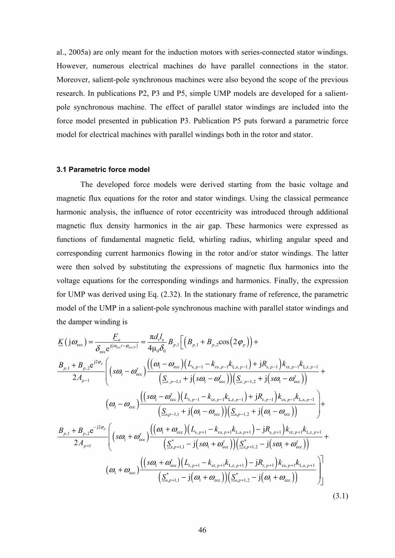
46
al., 2005a) are only meant for the induction motors with series-connected stator windings.
However, numerous electrical machines do have parallel connections in the stator.
Moreover, salient-pole synchronous machines were also beyond the scope of the previous
research. In publications P2, P3 and P5, simple UMP models are developed for a salient-
pole synchronous machine. The effect of parallel stator windings are included into the
force model presented in publication P3. Publication P5 puts forward a parametric force
model for electrical machines with parallel windings both in the rotor and stator.
3.1 Parametric force model
The developed force models were derived starting from the basic voltage and
magnetic flux equations for the rotor and stator windings. Using the classical permeance
harmonic analysis, the influence of rotor eccentricity was introduced through additional
magnetic flux density harmonics in the air gap. These harmonics were expressed as
functions of fundamental magnetic field, whirling radius, whirling angular speed and
corresponding current harmonics flowing in the rotor and/or stator windings. The latter
were then solved by substituting the expressions of magnetic flux harmonics into the
voltage equations for the corresponding windings and harmonics. Finally, the expression
for UMP was derived using Eq. (2.32). In the stationary frame of reference, the parametric
model of the UMP in a salient-pole synchronous machine with parallel stator windings and
the damper winding is
( ) ( ) ( )( )
( ) ( )( )( )( )( ) ( )( )
( )
ecc ecc.0
e r eecc ,1 ,1 ,2j
0 0ecc
j21 ecc s, 1 cs, 1 L,s, 1 s, 1 cr, 1 L,r, 1,1 ,2 r
1 ecc r r1 r, 1,1 1 ecc r, 1,2 1 ecc
11 ecc
πj cos 24µe
je2 j j
p
p p p pt
p p p p p pp p
p p p
F d lK B B B
L k k R k kB Bs
A S s S s
s
ω ϕ
ϕ
ω ϕδδ
ω ωω ω
ω ω ω ω
ωω ω
−
− − − − − −
− − −
⎡= = + +⎣
⎛ − − ++ ⎜ − +⎜ + − + −⎝
−( )( )( )
( )( ) ( )( )
( ) ( )( )( )
recc r, 1 cr, 1 L,r, 1 r, 1 cs, 1 L,s, 1
s, 1,1 1 ecc s, 1,2 1 ecc
j21 ecc s, 1 cs, 1 L,s, 1 s, 1 cr, 1 L,r, 1,1 ,2 r
1 ecc *1 r, 1,1 1 e
j
j j
je2 j
p
p p p p p p
p p
p p p p p pp p
p p
L k k R k k
S S
L k k R k kB Bs
A S s
ϕ
ω
ω ω ω ω
ω ωω ω
ω ω
− − − − − −
− −
−+ + + + + +
+ +
⎞− − +⎟ +⎟+ − + − ⎠
+ − −++
− +( )( ) ( )( )
( )( )( )( )
( )( ) ( )( )
r * rcc r, 1,2 1 ecc
r1 ecc r, 1 cr, 1 L,r, 1 r, 1 cs, 1 L,s, 1
1 ecc * *s, 1,1 1 ecc s, 1,2 1 ecc
j
j
j j
p
p p p p p p
p p
S s
s L k k R k k
S S
ω ω
ω ωω ω
ω ω ω ω
+
+ + + + + +
+ +
⎛⎜ +⎜ − +⎝
⎤⎞+ − −⎥⎟+⎥⎟− + − + ⎠⎦
(3.1)

47
here, ecc.0ϕ is initial phase angle of the rotor eccentricity; 0δ is nominal air gap; ,1pB is the
first constituent of the fundamental magnetic flux density component caused by interaction
of the fundamental MMF waves with constant permeance term; ,2pB is the second
constituent of the fundamental magnetic flux density component caused by interaction of
the fundamental MMF waves with the first Fourier series component of the air gap
permeance related to rotor saliency; pϕ is phase angle between the fundamental magnetic
flux density component and the fundamental MMF vector of the field winding; s is slip of
the rotor; 1ω is angular frequency of the supply voltage; reccω is whirling angular velocity
in rotor frame of reference; cr, 1pk ± are dimensionless coupling factors for p±1 current
harmonics in the damper winding; cs, 1pk ± are dimensionless coupling factors for p±1
current harmonics in the stator winding; L,r, 1pk ± are coefficients defining the amounts of the
corresponding magnetic flux harmonics that pass through the damper winding from
sources other than rotor currents; L,s, 1pk ± are coefficients defining the amounts of the
corresponding magnetic flux harmonics that pass through the stator winding from sources
other than stator currents; r, 1pL ± are inductances of the damper winding for p±1 magnetic
flux density harmonics; s, 1pL ± are inductances of the stator winding for p±1 magnetic flux
density harmonics; r, 1pR ± are resistances of the damper winding for p±1 current harmonics;
s, 1pR ± are resistances of the stator winding for p±1 current harmonics; 1pA ± , r, 1,1pS ± ,
r, 1,2pS ± , s, 1,1pS ± and s, 1,2pS ± are force model parameters, which can be expressed in terms of
the physical machine parameters listed above.
A synchronous machine in steady state operates with zero slip. However, in
expression (3.1), the slip symbol was kept in order to apply this force model to the
induction motor as well. To do so, the second constituent of the fundamental magnetic flux
density ,2pB has to be equated to zero, as this term is related to the rotor saliency. Thus, the
force model expression for induction machines becomes a little simpler than Eq. (3.1).
The detailed derivation of the force model (Eq. (3.1)) is given in Publication P5. As
can be seen, there are many unknown parameters in the force model expression. Estimation
of parameter values is a non-trivial task, which is briefly discussed in the following sub-
chapter.

48
3.2 Parameter estimation
FEM-based simulations of electrical machines provide sufficient data for the
estimation of unknown force model parameters. However, as several parameters are
encountered in the denominators, a direct application of the least-square method is not
possible. For this reason, a hybrid parameter estimation technique was elaborated
(Publication P1), which effectively combined the method of least squares with the GA-
based approach. The estimation task was shared between the two methods so that the
parameters located in the numerators were estimated using the least-square technique,
whereas the remaining parameters were estimated using GA. This approach showed
superior performance in comparison to the technique where the least-square method was
accompanied by the so-called sequential exhaustive search scheme. The supremacy was
especially evident when the number of unknown parameters in the denominators was
increased. An estimation procedure solely based on the GA was also implemented,
demonstrating fairly good performance. However, it required a longer computation time.
3.3 Conclusions
In this chapter, a parametric force model for electrical machines with parallel stator
windings and rotor cage (damper winding) is presented. The model is applicable to salient-
pole synchronous machines as well as to induction machines. It can also be used for other
electrical machines, which feature the parallel paths either in the rotor or stator winding.
The technique developed for the estimation of force model parameters is briefly discussed.

49
4 Discussion of the results
In this chapter, the performance of the parametric force models developed is
presented and discussed. Some phenomena arising from the interactions of the currents
circulating in the parallel circuits of the rotor and stator are highlighted. The influence of
the parallel stator windings on the net UMP and its components is examined. The effects of
parallel circuits in the rotor and those in the stator on the eccentricity force are compared.
The chapter is based on the data documented in Publications P2-P7.
4.1 Verification of the force models
As mentioned earlier, force models were developed for:
• salient-pole synchronous machines without the parallel stator windings
(Publication P2);
• induction and synchronous motors with parallel stator windings, but without the
rotor cage (damper winding) (Publication P3);
• induction and synchronous motors with parallel circuits both in the stator and
rotor windings (Publication P5).
The first two parametric force models with parameters estimated from the
numerical calculation results showed excellent performance. Figure 4.1 demonstrates a
very good agreement between the FRF calculated using the FEA and the FRF obtained by
substituting the estimated parameters into the force model. These FRFs of the force were
computed for the synchronous machine with damper winding only. The performance of the
force model applied to synchronous machine with four parallel paths in the stator winding
is shown in Figure 4.2. Similar results for the 15 kW cage induction motor with four
parallel stator windings are presented in Figure 4.3. In this motor, the influence of the rotor
cage on the UMP was annulled in the numerical simulation by using “air” as the material
of the rotor cage.

50
Figure 4.1 FRF calculated numerically vs. FRF obtained using the parametric force
model: eight-pole, 50 Hz salient-pole synchronous generator with damper
winding and series-connected stator winding at the rated load.
Figure 4.2 FRF calculated numerically vs. FRF obtained using the parametric force
model: eight-pole, 50 Hz salient-pole synchronous generator with parallel
stator windings but without damper winding at the rated load.
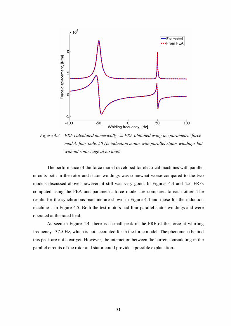
51
Figure 4.3 FRF calculated numerically vs. FRF obtained using the parametric force
model: four-pole, 50 Hz induction motor with parallel stator windings but
without rotor cage at no load.
The performance of the force model developed for electrical machines with parallel
circuits both in the rotor and stator windings was somewhat worse compared to the two
models discussed above; however, it still was very good. In Figures 4.4 and 4.5, FRFs
computed using the FEA and parametric force model are compared to each other. The
results for the synchronous machine are shown in Figure 4.4 and those for the induction
machine – in Figure 4.5. Both the test motors had four parallel stator windings and were
operated at the rated load.
As seen in Figure 4.4, there is a small peak in the FRF of the force at whirling
frequency –37.5 Hz, which is not accounted for in the force model. The phenomena behind
this peak are not clear yet. However, the interaction between the currents circulating in the
parallel circuits of the rotor and stator could provide a possible explanation.

52
Figure 4.4 FRF calculated numerically vs. FRF obtained using the parametric force
model: eight-pole, 50 Hz salient-pole synchronous generator with four
parallel stator windings and damper winding at the rated load.
Figure 4.5 FRF calculated numerically vs. FRF obtained using the parametric force
model: four-pole, 50 Hz induction motor with four parallel stator
windings and rotor cage at the rated load.
The force model developed for electrical machines with parallel circuits both in the
rotor and stator windings was also applied to the motors that were equipped with either the
53
parallel stator windings or the rotor cage (damper winding). In all these tests, the model
performed very well.
It is worth mentioning that the estimated set of force model parameters corresponds
to a certain operating point (supply voltage, load torque, etc.) of an electrical machine. Slot
harmonics are considered as one of the main reasons for the dependence of the
electromagnetic force on the loading. These have a very small whirling frequency
dependence in the range considered, but can vary significantly due to the load changes.
Moreover, as shown above, the configuration of the stator winding may influence
profoundly the shape of FRF of the UMP; therefore, different sets of parameters may have
to be used for a machine of the same geometry, but with different stator winding
connections.
4.2 Influence of parallel stator windings on the UMP constituents
The rotor eccentricity disturbs the symmetric distribution of the magnetic field in
the air gap of the motor by introducing many new magnetic field harmonics. The orders of
these harmonics differ by one (±1) from the orders of the harmonics, which already existed
in the machine with a concentric rotor. The interaction between these magnetic fields
causes the UMP. Of key importance are the harmonics related to the fundamental magnetic
field and those associated with slotting, as they constitute the major part of the UMP.
Figure 4.6 shows that the UMP due to these two components accounts for ¾ of the total
UMP.
In Publication P6, the influence of parallel stator windings on the total UMP and its
constituents is studied using the FEA. The results of this study showed that the parallel
stator windings effectively attenuate the net eccentricity force by suppressing significantly
the eccentricity harmonics related to the fundamental magnetic field. The slotting
harmonics are mitigated almost evenly in the whole whirling frequency range studied,
although not to such a great degree as the harmonics associated with the fundamental
magnetic field. It was shown that the reduction of the harmonics related to the fundamental
field and slotting accounts for the major part of the UMP mitigation by the parallel stator
windings.

54
Figure 4.6 Total UMP vs. the sum of two UMP constituents: four-pole, 50 Hz
induction motor with rotor cage and series-connected stator windings at
the rated load.
4.3 Other issues related to the parallel stator windings
Although, both the parallel stator windings and rotor cage tend to reduce the
eccentricity force, their effects on the UMP are still very different. Thus, the rotor cage,
containing usually a large number of parallel paths uniformly distributed around the rotor
circumference, evenly decreases the UMP magnitude, independently of the rotor-
eccentricity phase angle. The stator winding, on the other hand, contains normally fewer
parallel paths. Therefore, the degree of the UMP reduction by the stator winding may
depend on the position of the rotor axis displacement, causing the electromagnetic system
of the motor to behave anisotropically. Moreover, the degree, to which the UMP is affected
by the stator winding, may also depend heavily on the number of parallel paths. As seen in
Figure 4.7, the trace of the eccentricity force vector in the induction motor containing two
parallel paths in the stator winding (2PP) differs significantly from the UMP trace in the
same motor with four parallel paths (4PP). Unlike the latter trace, which is almost circular,
the former trace has considerably different values on the orthogonal axes. In both cases

55
simulated, the cylindrical circular rotor eccentricity was used, the whirling radius was 20%
of the nominal air gap and whirling frequency was –25 Hz.
This anisotropic UMP behaviour causes the results of numerical impulse response
test to deviate noticeably from the results of conventional FEM technique (forced whirling
method). In Publication P4, the performance of the impulse response test with different
combinations of stator and rotor windings layouts is investigated and some conclusions as
to the applicability of the method are drawn.
Figure 4.7 Traces of UMP in four-pole, 50 Hz induction motor with parallel stator
windings but without rotor cage at no load.
4.4 Parallel stator windings vs. rotor cage vs. parallel stator windings + rotor cage
Parallel connections in the rotor and stator windings have long been known to
effectively reduce the UMP. As the rotor cage (damper winding) usually contains many
more parallel circuits than the stator winding, it is natural to assume that motors equipped
with the rotor cage alone would experience a lower level of eccentricity force than those
where only the parallel stator windings are provided. Furthermore, motors with parallel
circuits both in the rotor and stator are expected to vibrate less than those with parallel
paths either in the rotor or stator.

56
According to the numerical calculation results presented in Figure 4.8, two parallel
stator windings indeed provide weaker UMP mitigation than the rotor cage alone. These
findings correspond to a standard 15 kW induction motor at no load. Besides, two parallel
stator windings may also cause the uneven UMP mitigation discussed above.
Figure 4.8 Comparison of FRFs of the UMP in four-pole, 50 Hz induction motor at
no load.
However, contrary to what was anticipated, an even lower average level of UMP
was attained in the whirling frequency range considered when the motor had four parallel
stator windings. Similar results were also observed in a salient-pole synchronous machine
operated at the rated load. As seen in Figure 4.9, the UMP when four parallel circuits are
provided in the stator winding is substantially lower than that in the machine equipped with
the damper winding only. These results show that already four parallel stator windings can
have a stronger impact on the UMP than the rotor cage (damper winding).
As expected, the smallest eccentricity forces are produced in the motors
incorporating parallel circuits both in the rotor and stator (see Figure 4.9).

57
Figure 4.9 Comparison of FRFs of the UMP in eight-pole, 50 Hz salient-pole
synchronous generator.
4.5 Conclusions
In this chapter, the main results of the thesis are presented and discussed in brief.
The presented parametric force models are verified using the numerical simulations of the
test motors. All force models exhibited a very good performance throughout the whole
whirling frequency range considered.
In this work, three electrical machines with different combinations of the rotor and
stator winding layouts were employed to investigate the performance of the force models
developed. In addition to the machines described in Tables 3.1 and 3.2, a six-pole, 50 Hz,
18.5 kW cage induction motor was used. Although the force models performed very well
with all these test machines, the applicability of the models to every type of electrical
machine cannot be guaranteed. However, these models continue the work started earlier by
Arkkio et al. (2000) and Holopainen et al. (2005a) and extend significantly the area of the
force models applicability by addressing the following electrical machines:
• salient- and non-salient-pole synchronous machines equipped with damper
winding and with series-connected stator windings;
58
• salient- and non-salient-pole synchronous machines equipped with parallel
stator windings and with no damper winding;
• induction motors equipped with parallel stator windings and with no rotor cage
(e.g., wound-rotor induction motor, blank-rotor induction motor);
• salient- and non-salient-pole synchronous machines equipped with damper
winding and with parallel stator windings;
• induction motors equipped with rotor cage and parallel stator windings.
Interaction between the currents circulating in the parallel circuits of the rotor and
stator may influence the UMP and alter the shape of its FRF to some extent. Although
being relatively small, the effects of this interaction could still be investigated further in
order to improve the accuracy of the parametric force models.
It was shown that the magnetic field harmonics associated with the fundamental
magnetic field and slotting contribute the most to the total UMP. The parallel stator
windings may considerably suppress these UMP constituents and, hence, reduce the net
UMP.
Parallel stator windings were shown to cause anisotropic UMP behaviour,
especially in electrical machines without the rotor cage (damper winding). These findings
conform well to the results presented by Robinson (1943). The author stated that there is
no damping of the UMP along the line between the two parallel stator windings. Due to
this UMP anisotropy, care should be exercised when applying the numerical impulse
response test to analyse such motors.
Parallel paths in the stator winding may provide a more efficient UMP mitigation
than the rotor cage (damper winding), even if the number of parallel circuits in the stator is
substantially lower than the number of parallel circuits in the rotor. Using parallel
connections in the rotor and stator simultaneously ensures the lowest level of the UMP.
The last statement agrees well with the results presented by Arkkio (1996).
The FEA results acquired in this work were not verified by measurements.
However, the employed finite-element models and numerical techniques for the
electromagnetic force calculation were previously validated by Arkkio et al. (2000), Lantto
et al. (2000) and Tenhunen et al. (2003d). The authors studied the electromagnetic forces
in a 15 kW induction motor with different types of rotor eccentricity using the technique
presented by Coulomb (1983). Antila et al. (1998) used Coulomb’s approach and the
method presented by Arkkio to calculate the electromagnetic forces in the radial active
59
magnetic bearings. In all these contributions, the authors reported a very good agreement
between the computed and measured results.
The force models developed were only tested with induction motors and a salient-
pole synchronous machine. However, the application area of the models could be extended
to other types of rotating electrical machines, especially if their construction is similar to
the construction of the motors studied in this work. Thus, by equating the term Bp,2 to zero,
the force model described by Eq. (3.1) can straightforwardly be applied to a cylindrical-
rotor synchronous machine. In permanent magnet synchronous motors, eccentricity
harmonics can induce eddy-currents in the permanent magnets located on the rotor surface.
The eddy-currents would reduce the magnetic field asymmetry and the resultant UMP. In
this way, the permanent magnets could be viewed as a rotor cage. Thus, the proposed force
models could also be applied to these electrical machines.
Although the developed force models were only tested on the electrical machines
with cylindrical circular rotor whirling, the models are also anticipated to perform well
with other types of rotor eccentricity. According to the results by Tenhunen et al. (2003d),
in electrical motor, the rotor motion of which can be described as the combination of
symmetric conical whirling and cylindrical circular whirling, the resultant electromagnetic
force on the rotor is almost the same as in the case of cylindrical circuit whirling, provided
the radii of symmetric conical whirling and cylindrical circular whirling are equal. Thus,
the developed force models could also be applied to describe the UMP in electrical motors
with such rotor whirling motion.
The rotors of both machines simulated were not skewed. The rotor skewing can
significantly affect the voltages induced in the rotor bars by the magnetic field harmonics,
especially the voltages induced by the magnetic field harmonics with short wavelengths
(e.g., harmonics related to stator and rotor slotting). The voltages induced in the rotor bars
by the eccentricity harmonics, which have relatively long wavelengths, remain virtually
unaltered by the skewing. Voltages induced in the rotor bars by a certain magnetic field
harmonic define the amount of damping of this harmonic produced by the rotor cage. Thus,
it is expected that the damping of slot harmonics by the skewed rotor cage can
substantially differ from the damping produced by the rotor cage with straight bars.
According to the results presented in Publication P6, slot harmonics contribute
significantly to the total unbalanced force. However, the UMP component related to
slotting has very small whirling frequency dependence, in the whirling frequency range
considered. As shown in Publication P6, peaks in the FRF of the electromagnetic force are

60
caused primarily by the eccentricity harmonics. Thus, rotor skewing, by affecting the
voltages induced in the rotor bars by the slot harmonics, can alter the average level of the
FRF of the electromagnetic force. Yet, the location of the peaks in the FRF of the force and
their elevation above the average FRF level are expected to be almost the same as in the
machine with straight rotor bars. Therefore, the force models developed are also expected
to be applicable to the machines with skewed rotors.

61
5 Summary
In this thesis, the UMP caused by the eccentric rotor is investigated in a wide
whirling frequency range. Two common types of electrical machine are considered: cage
induction motor and salient-pole synchronous machine. Special attention is drawn to the
effects of parallel stator windings on the UMP.
Simple analytical models describing the UMP are developed and verified using the
FEA. The parametric force models are built for: salient-pole synchronous machines
without the parallel stator windings; electrical motors with parallel circuits in the stator
only; and electrical machines with parallel paths both in the rotor and stator. The two force
models mentioned last were applied to the induction and synchronous motors. All the
presented models exhibited a very good performance throughout the whole whirling
frequency range considered.
Parallel stator windings, similarly to the rotor cage (damper winding), effectively
reduce the UMP. Especially the UMP constituents related to the fundamental magnetic
field and slotting are strongly affected by the parallel paths in the stator. However, unlike
the rotor cage, the parallel stator windings may instigate anisotropy in the UMP. In such
cases, the results of the numerical impulse response test may differ significantly from the
conventional calculation results.
Despite the fact that the number of parallel circuits in the stator is often
substantially lower than the number of parallel circuits in the rotor, the parallel paths in the
stator winding may still provide a more efficient UMP mitigation than the rotor cage
(damper winding).
When parallel circuits are provided both in the rotor and stator, the smallest amount
of the UMP is expected. However, currents circulating in these parallel paths may interact
with each other, thus affecting the UMP and the shape of its FRF.

62
References
Al-Nuaim, N. A., Toliyat, H. A. 1997. A method for dynamic simulation and detection of dynamic air-gap eccentricity in synchronous machines. Proceedings of the IEEE International Electric Machines and Drives Conference, Milwaukee, USA, pp. MA2 5.1-5.3.
Al-Nuaim, N. A., Toliyat, H. A. 1998. Novel method for modeling dynamic air-gap eccentricity in synchronous machines based on modified winding function theory. IEEE Transactions on Energy Conversion, Vol. 13, No. 2, pp. 156-162.
Antila, M., Lantto, E., Arkkio, A. 1998. Determination of forces and linearised parameters of radial active magnetic bearings by finite element technique. IEEE Transactions on Magnetics, Vol. 34, No. 3, pp. 684-694.
Arkkio, A. 1987. Analysis of induction motors based on the numerical solution of the magnetic field and circuit equations. Acta Polytechnica Scandinavica, Electrical Engineering Series, No. 59, Helsinki, 97 p. Available at: http://lib.tkk.fi/Diss/. ISBN 951-666-250-1. (Doctoral thesis).
Arkkio, A., Lindgren, O. 1994. Unbalanced magnetic pull in a high-speed induction motor with an eccentric rotor. Proceedings of the International Conference on Electrical Machines, September 5-8, 1994, Paris, France, Vol. 1, pp. 53-58.
Arkkio, A. 1996. Unbalanced magnetic pull in cage induction motors – dynamic and static eccentricity. Proceedings of the International Conference on Electrical Machines, September 10-12, 1996, Vigo, Spain, pp. 192-197.
Arkkio, A. 1997. Unbalanced magnetic pull in cage induction motors with asymmetry in rotor structures. Eighth International Conference on Electrical Machines and Drives EMD-97, Conference Publication No. 444, September 1-3, 1997, pp. 36-40.
Arkkio, A., Antila, M., Pokki, K., Simon, A., Lantto, E. 2000. Electromagnetic force on a whirling cage rotor. IEE Proceedings – Electric Power Applications, Vol. 147, No. 5, pp. 353-360.
Bastos, J. P. A., Sadowski, N. 2003. Electromagnetic modeling by finite element methods. Marcel Dekker, New York, 490 p.
Belmans, R., Geysen, W., Jordan, H., Vandenput, A. 1982a. Unbalanced magnetic pull and homopolar flux in three-phase induction motors with eccentric rotors. Proceedings of ICEM’82, pp. 916-921.
Belmans, R., Geysen, W., Jordan, H., Vandenput, A. 1982b. Unbalanced magnetic pull in three-phase two-pole motors with eccentric rotor. Proceedings of International Conference on Electrical Machines – Design and Application, London, pp. 65-69.
Belmans, R., Vandenput, A., Geysen, W. 1985 .Determination of the parameters of the radial vibrations of large electric motors. Symposium on Electromechanics and Industrial

63
Electronics Applied to Manufacturing Processes, September 17-19, 1985, San Felice Circeo, Italy, pp. 113-119.
Belmans, R., Vandenput, A., Geysen, W. 1987. Calculation of the flux density and the unbalanced pull in two pole induction machines. Electrical Engineering (Archiv fur Elektrotechnik), Vol. 70, No. 3, pp 151-161.
Berman, M. 1993. On the reduction of magnetic pull in induction motors with off-centre rotor. Conference Record of the IEEE Industry Applications Society Annual Meeting, October 2-8, 1993, Vol. 1, pp. 343-350.
Binns, K. J., Dye, M. 1973. Identification of principal factors causing unbalanced magnetic pull in cage induction motors, Proceeding IEE, Vol. 120, No. 3, pp. 349-354.
Bossio, G., De Angelo, C., Solsona, J., Garcia, G., Valla, M. I. 2004. A 2-d model of the induction machine: an extension of the modified winding function approach. IEEE Transactions on Energy Conversion, Vol. 19, No. 1, pp. 144-150.
Cai, W., Pillay, P., Reichert, K. 2001. Accurate computation of electromagnetic forces in switched reluctance motors. Proceedings of the Fifth International Conference on Electrical Machines and Systems, ICEMS 2001, August 18-20, 2001, Vol. 2, pp. 1065-1071.
Chari, M. V. K., Silvester, P. P. 1980. Finite elements in electrical and magnetic field problems. J. Wiley & Sons, New York, 219 p.
Chari, M., Konrad, A., Palmo, M., D’Angelo, J. 1982. Three-dimensional vector potential analysis for machine field problems. IEEE Transactions on Magnetics, Vol. 18, No. 2, pp. 436-446.
Coulomb, J. L. 1983. A methodology for the determination of global electromechanical quantities from a finite element analysis and its application to the evaluation of magnetic forces, torques and stiffness. IEEE Transactions on Magnetics, Vol. 19, No. 6, pp 2514-2519.
Covo, A. 1954. Unbalanced magnetic pull in induction motors with eccentric rotors. AIEE Transactions, Vol. 73, pp. 1421-1425.
DeBortoli, M. J., Salon, S. J., Burow, D. W., Slavik, C. J. 1993. Effects of rotor eccentricity and parallel windings on induction machine behaviour: a study using finite element analysis. IEEE Transactions on Magnetics, Vol. 29, No. 2, pp. 1676-1682.
Dorrell, D. G. 1993. Calculation of unbalanced magnetic pull in cage induction machines. Cambridge: University of Cambridge. 169 p. (Doctoral thesis).
Dorrell, D. G., Smith, A. C. 1994. Calculation of UMP in induction motors with series or parallel winding connections. IEEE Transactions on Energy Conversion, Vol. 9, No. 2, pp. 304-310.
64
Dorrell, D. G. 1995a. The influence of rotor skew on unbalanced magnetic pull in cage induction motors with eccentric rotors. Seventh International Conference on Electrical Machines and Drives, September 11-13, 1995, Conference Publication No. 412, pp. 67-71.
Dorrell, D. G. 1995b. The sources and characteristics of unbalanced magnetic pull in cage induction motors with either static or dynamic rotor eccentricity. Proceedings of Stockholm Power Tech, June 18-22, 1995, Stockholm, Sweden. Vol. Electrical Machines and Drives, pp. 229-234.
Dorrell, D. G. 1996. Calculation of unbalanced magnetic pull in small cage induction motors with skewed rotors and dynamic rotor eccentricity. IEEE Transactions on Energy Conversion, Vol. 11, No. 3, pp. 483-488.
Dorrell, D. G. 1999. Experimental behaviour of unbalanced magnetic pull in 3-phase induction motors with eccentric rotors and the relationship with tooth saturation. IEEE Transactions on Energy Conversion, Vol. 14, No. 3, pp. 304-309.
Dorrell, D. G. 2000. Modelling of non-uniform rotor eccentricity and calculation of unbalanced magnetic pull in a 3-phase cage induction motors. Proceeding of ICEM 2000, August 28-30, 2000, Espoo, Finland, pp. 1820-1824.
Dorrell, D. G., Ooshima, M., Chiba, A. 2003. Force analysis of a buried permanent-magnet bearingless motor. IEEE International Electric Machines and Drives Conference, IEMDC 2003, June 1-4, 2003, Vol. 2, pp. 1091-1097.
Ellison, A. J., Moore, C. J. 1968. Acoustic noise and vibration of rotating electric machines. IEE Proceedings, Vol. 115, No. 11, pp. 1633-1640.
Felippa, C. A. 2001. A historical outline of matrix structural analysis: a play in three acts. Computers and Structures, Vol. 79, No. 14, pp. 1313-1324.
Fisher-Hinnen, J. 1899. Dynamo design. Van Nostrand.
Freise, W., Jordan, H. 1962. Unbalanced magnetic pull in 3-phase a.c. machines. ETZ-A, Vol. 83, No. 9, pp. 299-303; Translation: CE Trans. 7836.
Frohne, H. 1967. The practical importance of unbalanced magnetic pull, possibilities of calculating and damping it. Conti Elektro Berichte, Vol. 13, pp. 81-92. Translation: ERA Transactions 1B2617.
Fruchtenicht, J., Jordan, H., Seinsch, H. O. 1982. Exzentrizitätsfelder als Ursache von Lafinstabilitäten bei Asynchronmaschinen. Teil I und II. Archiv fur Elektrotechnik, Vol. 65, pp. 271-292.
Garrigan, N. R., Soong, W. L., Stephens, C. M., Storace, A., Lipo, T. A. 1999. Radial force characteristics of a switched reluctance machine. Industry Applications Conference, Thirty-fourth IAS Annual Meeting, October 3-7, 1999, Vol. 4, pp. 2250-2258.
Gray, A., Pertsch, J. G. 1918. Critical review of the bibliography on unbalanced magnetic pull in dynamo-electric machines. AIEE Transactions, Vol. 37, Part 2, pp. 1417-1424.

65
Haase, H., Jordan, H., Kovacs, K. P. 1972. Vibratory forces as a result of shaft fluxes with two-pole induction machines. Electrotech. (ETZ), Vol. 93, pp. 485-486. Translation: CEGB CE 7822.
Heller, B., Jokl, A. L. 1969. Tangential forces in squirrel-cage induction motors. IEEE Transactions on Power Apparatus and Systems, Vol. 88, No. 4, pp. 484-492.
Hellmund, R. E. 1907. Series versus parallel windings for a.c. motors. Electrical World, No. 49, pp. 388-389.
Holopainen, T. P. 2004. Electromechanical interaction in rotordynamics of cage induction motors. Espoo: VTT Technical Research Centre of Finland, VTT Publications 543, 64 p. Available at: http://lib.tkk.fi/Diss/. ISBN 951-38-6404-9. (Doctoral thesis).
Holopainen, T. P., Tenhunen, A., Lantto, E., Arkkio, A. 2005a. Unbalanced magnetic pull induced by arbitrary eccentric motion of cage rotor in transient operation. Part 1: Analytical model. Electrical Engineering (Archiv fur Elektrotechnik), Vol. 88, No. 1, pp. 13-24.
Holopainen, T. P., Tenhunen, A., Lantto, E., Arkkio, A. 2005b. Unbalanced magnetic pull induced by arbitrary eccentric motion of cage rotor in transient operation. Part 2: Verification and numerical parameter estimation. Electrical Engineering (Archiv fur Elektrotechnik), Vol. 88, No. 1, pp. 25-34.
Joksimovic, G. M., Durovic, M. D., Obradovic, A. B. 1999. Skew and linear rise of MMF across slot modeling – winding function approach. IEEE Transactions on Energy Conversion, Vol. 14, No. 3, pp. 315-320.
Joksimovic, G. M., Penman, J. 2000. The detection of inter-turn short circuits in the stator windings of operating motors. IEEE Transactions on Industrial Electronics, Vol. 47, No. 5, pp. 1078-1084.
Joksimovic, G. M., Durovic, M. D., Penman, J., Arthur, N. 2000. Dynamic Simulation of Dynamic Eccentricity in Induction Machines – Winding Function Approach. IEEE Transactions on Energy Conversion, Vol. 15, No. 2, pp. 143-148.
Jordan, H., Roder, G., Weis, M. 1967. Under what circumstances may mechanical vibrations of the stator core be expected at supply frequency in four-pole three-phase asynchronous machines? Elecktrie, Vol. 21, No. 3, pp. 91-95; Translation: ERA Trans. 1B2578.
von Kaehne, P. 1963. Unbalanced magnetic pull in rotating electrical machines. Survey of published work. ERA Report, ref.: Z/T 142, 1963, 30 p.
Kim, U., Lieu, D. K. 1998. Magnetic field calculation in permanent magnet motors with rotor eccentricity: without slotting effect. IEEE Transactions on Magnetics, Vol. 34, No. 4, Part 2, pp. 2243-2252.

66
Kovacs, K. P. 1977. Two-pole induction-motor vibrations caused by homopolar alternating fluxes. IEEE Transactions on Power Apparatus and Systems, Vol. PAS-96, No. 4, pp. 1105-1108.
Krondl, M. 1956. Self excited radial vibrations of the rotor of induction machines with parallel paths in the winding. Bull. Assoc. Suisse. Elect., Vol. 47, pp. 581-588.
Kyung-Tae Kim; Kwang-Suk Kim; Sang-Moon Hwang; Tae-Jong Kim; Yoong-Ho Jung. 2001. Comparison of magnetic forces for IPM and SPM motor with rotor eccentricity. IEEE Transactions on Magnetics, Vol. 37, No. 5, Part 1, pp. 3448-3451.
Lantto, E., Arkkio, A., Antila, M., Pokki, K., Simon, A. 2000. Electromagnetic forces caused by cage induction motor. 7-th International Symposium on Magnetic Bearings, August 23-25, 2000, ETH Zurich, pp. 589-594.
Li, J. T., Liu, Z. J., Nay, L. H. 2007. Effect of radial magnetic forces in permanent magnet motors with rotor eccentricity. IEEE Transactions on Magnetics, Vol. 43, No. 6, pp. 2525-2527.
Lipo, T. A. 1987. Theory and control of synchronous machines. University of Winconsin-Madison.
Lundstrom, L., Gustavsson, R., Aidanpaa, J.-O., Dahlback, N., Leijon, M. 2007. Influence on the stability of generator rotors due to radial and tangential magnetic pull force. IET Electric Power Applications, Volume. 1, No. 1, pp. 1-8.
Luo, X., Liao, Y., Toliyat, H. A., El-Antably, A., Lipo, T. A. 1995. Multiple coupled circuit modeling of induction machines. IEEE Transactions on Industry Applications, Vol. 31, No. 2, pp. 311-318.
Luomi, J. 1993. Finite element methods for electrical machines. Lecture notes for a postgraduate course in electrical machines. Chalmers University of Technology, Department of Electrical Machines and Power Electronics, Göteborg.
Martin, H. C., Carey G. F. 1973 . Introduction to finite element analysis – Theory and applications. McGraw-Hill Publ., New York, 386 p. ISBN 0-07-040641-3.
Milimonfared, J., Kelk, H. M., Nandi, S., Minassians, A. D., Toliyat, H. A. 1999. A novel approach for broken-rotor-bar detection in cage induction motors. IEEE Transactions on Industry Applications, Vol. 35, No. 5, pp. 1000-1006.
Mizia, J., Adamiak, K., Eastham, A. R., Dawson, G. E. 1988. Finite element force calculation: Comparison of methods for electric machines. IEEE Transactions on Magnetics, Vol. 24, No. 1, pp. 447-450.
Nandi, S., Toliyat, H. A., Parlos, A. G. 1997. Performance analysis of a single phase induction motor under eccentric conditions. IEEE Industry Applications Society, Annual Meeting, October 5-9, 1997, New Orleans, Louisiana, USA, pp. 174-181.
Nandi, S., Bharadwaj, R. M., Toliyat, H. A., Parlos, A. G. 1998. Performance analysis of a three phase induction motor under mixed eccentricity condition. Proceeding of

67
International Conference on Power Electronic Drives and Energy Systems for Industrial Grows, Vol. 1, December 1-3, 1998, pp. 123-128.
Nandi, S., Ahmed, S., Toliyat, H. A. 2001. Detection of rotor slot and other eccentricity related harmonics in a three phase induction motor with different rotor cages. IEEE Transactions on Energy Conversion, Vol. 16, No. 3, pp. 253-260.
Nandi, S., Toliyat, H. A. 2002. Novel frequency-domain-based technique to detect stator interturn faults in induction machines using stator-induced voltages after switch-off. IEEE Transactions on Industry Applications, Vol. 38, No. 1, pp. 101-109.
Neves, C. G. C., Carlson, R., Sadowski, N., Bastos, J. P. A., Soeiro, N. S., Gerges, S. N. Y. 1998. Vibrational behavior of switched reluctance motors by simulation and experimental procedures. IEEE Transactions on Energy Conversion, Vol. 34, No. 5, pp. 3158-3161.
Perers, R., Lundin, U., Leijon, M. 2007. Saturation effects on unbalanced magnetic pull in a hydroelectric generator with an eccentric rotor. IEEE Transactions on Magnetics, Vol. 43, No. 10, pp 3884-3890.
Reichert, K., Freundl, H., Vogt, W. 1976. The calculation of forces and torques within numerical magnetic field calculation methods. Compumag conference, Oxford 1976, pp. 64-73.
Robinson, R. C. 1943. The calculation of unbalanced magnetic pull in synchronous and induction motors. AIEE Transactions, Vol. 62, pp. 620-624.
Robinson, R. C. 1963. Line frequency magnetic vibrations of A.C. machines. AIEE Transactions on Power Apparatus and Systems, Vol. 81, pp. 675-679.
Rosenberg, E. 1918. Magnetic pull in electric machines. Transactions of the American Institute of Electrical Engineers (AIEE), Vol. 37, Part 2, New York, N.Y., USA, pp. 1425-1469.
Sadowski, N., Lefevre, Y., Lajoie-Mazenc, M., Cros, J. 1992. Finite element torque calculation in electrical machines while considering the movement. IEEE Transactions on Magnetics, Vol. 28, No. 2, pp. 1410-1413.
Salon, S. J., DeBortoli, M. J., Burow, D. W., Slavik, C. J. 1992. Calculation of circulating current between parallel windings in induction motors with eccentric rotors by finite element method. International Conference on Electrical Machines, September 15-17, 1992, Manchester, UK, pp. 371-375.
Salon, S., Sivasubramaniam, K., Ergene, L. T. 2001. The effect of asymmetry on torque in permanent magnet motors. IEEE International Electric Machines and Drives Conference, IEMDC 2001, pp. 208-217.
Schlensok, C., Henneberger, G. 2004. Calculation of force excitations in induction machines with centric and excentric positioned rotor using 2-d transient FEM. IEEE Transactions on Magnetics, Vol. 40, No. 2, pp. 782-785.

68
Schuisky, V. W. 1971. Magnetic pull in electrical machines due to eccentricity of the rotor. Electrotech. Masch. Ball, Vol. 88, pp. 391-399. Translation: ERA 2958.
Silvester, P. P., Ferrari, R. L. 1996. Finite elements for electrical engineers. Third Edition, Cambridge University Press, 512 p.
Smith, A. C., Dorrell, D. G. 1996. Calculation and measurement of unbalanced magnetic pull in cage induction motors with eccentric rotors. Part 1: Analytical model. IEE Proceedings – Electric Power Applications, Vol. 143, No. 3, pp. 193-201.
Stavrou, A., Penman, J. 2001. Modelling dynamic eccentricity in smooth air-gap induction machines. IEEE International Electric Machines and Drives Conference, IEMDC 2001, pp. 864-871.
Summers, E. W. 1955. Vibration in 2-pole induction motors related to slip frequency. AIIE Transactions, Vol. 74, pp. 69-72.
Swann, S. A. 1963. Effect of rotor eccentricity on the magnetic field in the air-gap of a non-salient-pole machine. IEE Proceedings, Vol. 110, No. 5, pp. 903-915.
Tarnhuvud, T., Reichert, K. 1988. Accuracy problems of force and torque calculation in FE-systems. IEEE Transactions on Magnetics, Vol. 24, No. 1, pp. 443-446.
Tenhunen, A. 2001. Finite-element calculation of unbalanced magnetic pull and circulating current between parallel windings in induction motor with non-uniform eccentric rotor. Proceedings of Electromotion’01, June 19-20, 2001, Bologna, Italy, pp. 19-24. Available at: http://lib.tkk.fi/Diss/2003/isbn9512266830/.
Tenhunen, A. 2003. Electromagnetic forces acting between the stator and eccentric cage rotor. Espoo: Helsinki University of Technology. (Laboratory of Electromechanics, Report series No. 69, 40 p.). Available at: http://lib.tkk.fi/Diss/. ISBN 951-22-6682-2. (Doctoral thesis).
Tenhunen, A. 2005. Calculation of eccentricity harmonics of the air-gap flux density in induction machines by impulse method. IEEE Transactions on Magnetics, Vol. 41, No. 5, pp. 1904-1907.
Tenhunen, A., Holopainen, T. P., Arkkio, A. 2003a. Impulse method to calculate the frequency response of the electromagnetic forces on whirling cage rotors. IEE Proceedings – Electric Power Applications, Vol. 150, No. 6, pp. 752-756.
Tenhunen, A., Holopainen, T. P., Arkkio, A. 2003b. Effects of equalizing currents on electromagnetic forces of whirling cage rotor. The IEEE International Electric Machines and Drives Conference IEMDC’03, June 1-4, 2003, Vol. 1, pp. 257-263.
Tenhunen, A., Benedetti, T., Holopainen, T. P., Arkkio, A. 2003c. Electromagnetic forces in cage induction motors with rotor eccentricity. The IEEE International Electric Machines and Drives Conference IEMDC’03, June 1-4, 2003, Vol. 3, pp. 1616-1622.

69
Tenhunen, A., Benedetti, T., Holopainen, T. P., Arkkio, A. 2003d. Electromagnetic forces of the cage rotor in conical whirling motion. IEE Proceedings - Electric Power Applications, Vol. 150, No. 5, pp. 563-568.
Tenhunen, A., Holopainen, T. P., Arkkio, A. 2004. Effects of saturation on the forces in induction motors with whirling cage rotor. IEEE Transactions on Magnetics, Vol. 40, No. 2, pp. 766-769.
Timar, P. L. 1989. Noise and vibration of electrical machines. Elsevier Science Publishers, Amsterdam – Oxford – New York – Tokyo, 339 p., ISBN 0-444-98896-3.
Toliyat, H. A., Al-Nuaim, N. A. 1997. Simulation and detection of dynamic air-gap eccentricity in salient pole synchronous machine. IEEE Industry Applications Society Annual Meeting, October 5-9, 1997, New Orleans, USA, pp. 255-262.
Toliyat, H. A., Lipo, T. A. 1995. Transient analysis of cage induction machines under stator, rotor bar and end ring faults. IEEE Transactions on Energy Conversion, Vol. 10, No. 2, pp. 241-247.
Vandevelde, L., Melkebeek, J. A. A. 1994. Theoretical and experimental study of radial forces in relation to magnetic noise of induction motors. International Conference on Electrical Machines ICEM-1994, 3, pp. 419-424.
Wignall, A. N., Gilbert, A. J., Yang, S. J. 1988. Calculation of forces on magnetised ferrous cores using the Maxwell stress method. IEEE Transactions on Magnetics, Vol. 24, No. 1, pp. 459-462.
Williamson, S. 1983. Power factor improvement in cage rotor induction motors. IEE Proceedings – Electric Power Applications, Vol. 130, No. 2, Part B, pp. 121-129.
Williamson, S., Smith, A. C. 1982. Steady-state analysis of 3-phase cage motors with rotor-bar and end-ring faults. IEE Proceedings – Electric Power Applications, Vol. 129, No. 3, Part B, pp. 93-100.
Williamson, S., Mirzoian, K. 1985. Analysis of cage induction motors with stator winding faults. IEEE Transactions on Power Apparatus and Systems, Vol. PAS-104, No. 7, pp. 1838-1842.
Williamson, S., Abdel-Magied, M. A. S. 1987. Steady-state analysis of double-cage induction motors with rotor-cage faults. IEE Proceedings – Electric Power Applications, Vol. 134, No. 4, Part B, pp. 199-206.
Williamson, S., Adams, N. K. 1989. Cage induction motors with inter-rings. IEE Proceedings – Electric Power Applications, Vol. 136, No. 6, Part B, pp. 263-274.
Yang, S. J. 1975. Acoustic noise from small 2-pole single-phase induction machines. Proceeding IEE, Vol. 122, pp. 1391-1396.
Zhu, Z. Q., Howe, D. 1997. Effect of rotor eccentricity and magnetic circuit saturation on acoustic noise and vibration of single-phase induction motors. Electric Machines and Power Systems, Vol. 25, pp. 443-457.

70

ISBN 978-951-22-9005-5ISBN 978-951-22-9006-2 (PDF)ISSN 1795-2239ISSN 1795-4584 (PDF)