Modelling of the Francis turbine runner in power stations ... · Modelling of the Francis turbine...
7
Modelling of the Francis turbine runner in power stations. Part II: stress analysis R. A. Saeed 1 , A. N. Galybin 1 , V. Popov 1 & N. O. Abdulrahim 2 1 Wessex Institute of Technology, UK 2 Sulaimani University, Iraq Abstract The second part of this paper presents results of stress analysis of the whole Francis turbine runner at Derbendikan power station by using the Finite Element Method (FEM). Computations were carried out with appropriate boundary and loading conditions for water pressure obtained from CFD analysis. The analysis focuses on stress distribution in the runner blades. It has been found that the maximum stresses due to the water pressure are located at the trailing edge of the runner blade towards the transition between the blade and the crown. This explains why this region has been identified as a critical area for fatigue crack initiation in the Francis turbine runner. Keywords: Francis turbine runner, fatigue cracks, FEM stress analysis. 1 Introduction Stress analysis of hydraulic turbine runners can only be performed by numerical methods due to the complexity of these structures. In this study, the loads obtained from the CFD analysis for specific boundary conditions (presented in the first part of the paper) are incorporated into a Finite Element model to calculate stress distributions in the runner. Finite Element modelling has been used by many researchers, e.g. by Angehrn et al. [1], to calculate stresses in a blade of the model turbine for different distributions of hydraulic loadings and by Nava et al. [2] to find hydraulic induced stresses in the Francis runner. Comparison finite element analysis with strain gauge measurements in an operating Francis turbine was presented [1, 3–6]; the calculated results obtained by the finite element method were in satisfactory agreement with the experimental results. www.witpress.com, ISSN 1743-3509 (on-line) WIT Transactions on The Built Environment, Vol 105, © 2009 WIT Press Fluid Structure Interaction V 279 doi:10.2495/FSI090261
Transcript of Modelling of the Francis turbine runner in power stations ... · Modelling of the Francis turbine...
Modelling of the Francis turbine runner in power stations. Part II: stress analysis
R. A. Saeed1, A. N. Galybin1, V. Popov1 & N. O. Abdulrahim2 1Wessex Institute of Technology, UK 2Sulaimani University, Iraq
Abstract
The second part of this paper presents results of stress analysis of the whole Francis turbine runner at Derbendikan power station by using the Finite Element Method (FEM). Computations were carried out with appropriate boundary and loading conditions for water pressure obtained from CFD analysis. The analysis focuses on stress distribution in the runner blades. It has been found that the maximum stresses due to the water pressure are located at the trailing edge of the runner blade towards the transition between the blade and the crown. This explains why this region has been identified as a critical area for fatigue crack initiation in the Francis turbine runner. Keywords: Francis turbine runner, fatigue cracks, FEM stress analysis.
1 Introduction
Stress analysis of hydraulic turbine runners can only be performed by numerical methods due to the complexity of these structures. In this study, the loads obtained from the CFD analysis for specific boundary conditions (presented in the first part of the paper) are incorporated into a Finite Element model to calculate stress distributions in the runner. Finite Element modelling has been used by many researchers, e.g. by Angehrn et al. [1], to calculate stresses in a blade of the model turbine for different distributions of hydraulic loadings and by Nava et al. [2] to find hydraulic induced stresses in the Francis runner. Comparison finite element analysis with strain gauge measurements in an operating Francis turbine was presented [1, 3–6]; the calculated results obtained by the finite element method were in satisfactory agreement with the experimental results.
www.witpress.com, ISSN 1743-3509 (on-line) WIT Transactions on The Built Environment, Vol 105, © 2009 WIT Press
Fluid Structure Interaction V 279
doi:10.2495/FSI090261
The data used in modelling refers to Unit 2 of the Derbendikan hydropower station (one of the major suppliers of electrical power generation in the north of Iraq (Kurdistan Region)) and is as follows: number of runner blades 13, number of guide vanes 24, rated head 80 m, power output at rated head 83 MW, discharge at rated head 113 m3/s, rotational speed 187.5 rpm [7].
2 Stress analyses in the Francis turbine runner
Stress analysis of the runner is an important issue that provides structural integrity of the turbine. In this study the analysis has been performed by using ANSYS, which is an effective tool for modelling stresses in Francis turbine runners, see e.g. [2, 8]. A number of tests have been performed in order to establish the degree of accuracy to be expected before carrying out the runner analysis.
2.1 Geometry model
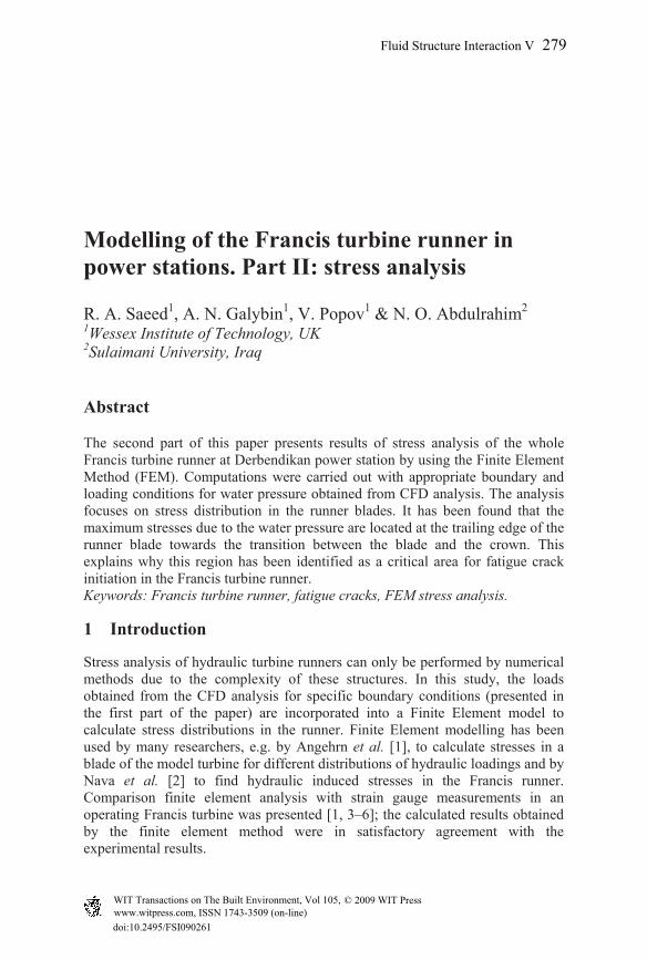
The geometric model used in this study (shown in Figure 1) consists of three distinct parts: the crown, blades and band. The model has been created according to the dimensions taken from the runner in the field. The geometry of the crown and band follow the drawings; however, the surfaces of the blade were modelled by transferred points from the prototype.
Figure 1: Model of the runner.
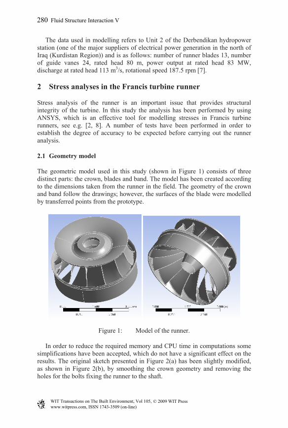
In order to reduce the required memory and CPU time in computations some simplifications have been accepted, which do not have a significant effect on the results. The original sketch presented in Figure 2(a) has been slightly modified, as shown in Figure 2(b), by smoothing the crown geometry and removing the holes for the bolts fixing the runner to the shaft.
www.witpress.com, ISSN 1743-3509 (on-line) WIT Transactions on The Built Environment, Vol 105, © 2009 WIT Press
280 Fluid Structure Interaction V
(a) (b)
Figure 2: Simplified model of the crown.
Figure 3: Finite element mesh of the runner model used in the analysis.
2.2 Discretization process
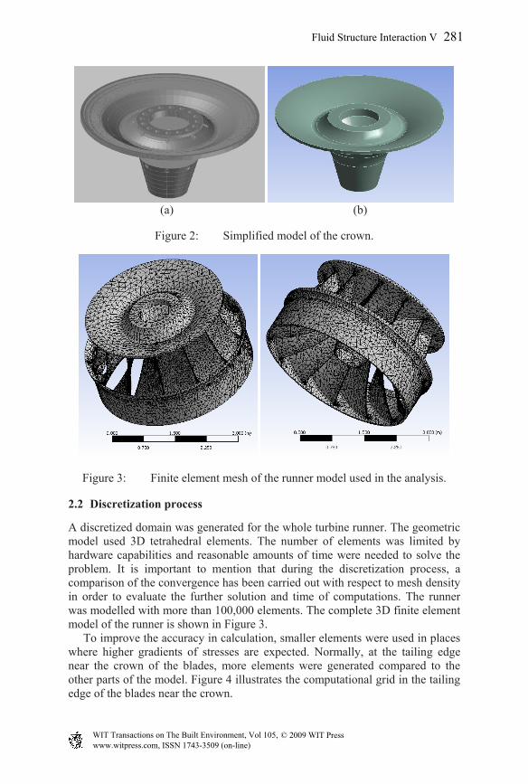
A discretized domain was generated for the whole turbine runner. The geometric model used 3D tetrahedral elements. The number of elements was limited by hardware capabilities and reasonable amounts of time were needed to solve the problem. It is important to mention that during the discretization process, a comparison of the convergence has been carried out with respect to mesh density in order to evaluate the further solution and time of computations. The runner was modelled with more than 100,000 elements. The complete 3D finite element model of the runner is shown in Figure 3. To improve the accuracy in calculation, smaller elements were used in places where higher gradients of stresses are expected. Normally, at the tailing edge near the crown of the blades, more elements were generated compared to the other parts of the model. Figure 4 illustrates the computational grid in the tailing edge of the blades near the crown.
www.witpress.com, ISSN 1743-3509 (on-line) WIT Transactions on The Built Environment, Vol 105, © 2009 WIT Press
Fluid Structure Interaction V 281

Figure 4: Surface grid refinement in the joint between blade and crown.
2.3 Loading condition
Under normal operating conditions, a Francis turbine runner is subjected to two sorts of static loads, namely, the centrifugal force due to the rotational speed and the load due to the water pressure. In the Francis turbines, the stresses due to centrifugal force during normal operation is much smaller than the stresses due to water pressure [2, 8], therefore centrifugal forces are neglected further on. The loading due to water pressure on the blades are considered and the pressure loading has been derived from CFD computations.
2.4 Boundary conditions
To ensure that the model acts the same way as the prototype, the constraints and appropriate boundary conditions were applied for the runner. Displacement boundary conditions are needed to constrain the runner, the runner will not be allowed to rotate at the support therefore the displacement vectors are zero (Ux=Uy=Uz=0). The pressure distribution on the fluid structure interface come from the water flow in the runner, it is computed from CFD analysis for specific operating conditions. Therefore
CFDn P , where σn and P are water pressure and
normal stress, shear stresses components are set to zero.
2.5 Analysis result and discussion
The 3D FEM for the whole structure of a Francis runner has been performed by ANSYS to evaluate stress distribution of the runner for specific operating conditions. The stress distributions are shown in the Figure 5, as evident from the figure, the maximum stresses are evident at the transition between blade and
www.witpress.com, ISSN 1743-3509 (on-line) WIT Transactions on The Built Environment, Vol 105, © 2009 WIT Press
282 Fluid Structure Interaction V
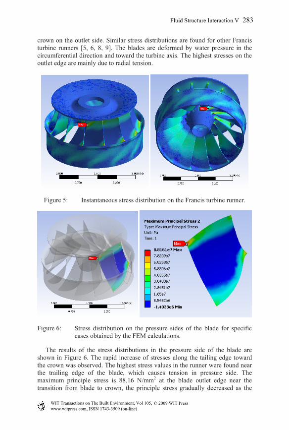
crown on the outlet side. Similar stress distributions are found for other Francis turbine runners [5, 6, 8, 9]. The blades are deformed by water pressure in the circumferential direction and toward the turbine axis. The highest stresses on the outlet edge are mainly due to radial tension.
Figure 5: Instantaneous stress distribution on the Francis turbine runner.
Figure 6: Stress distribution on the pressure sides of the blade for specific cases obtained by the FEM calculations.
The results of the stress distributions in the pressure side of the blade are shown in Figure 6. The rapid increase of stresses along the tailing edge toward the crown was observed. The highest stress values in the runner were found near the trailing edge of the blade, which causes tension in pressure side. The maximum principle stress is 88.16 N/mm2 at the blade outlet edge near the transition from blade to crown, the principle stress gradually decreased as the
www.witpress.com, ISSN 1743-3509 (on-line) WIT Transactions on The Built Environment, Vol 105, © 2009 WIT Press
Fluid Structure Interaction V 283
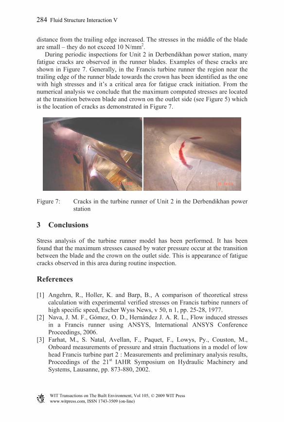
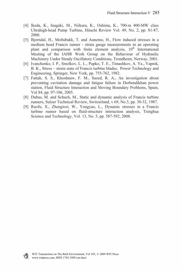
distance from the trailing edge increased. The stresses in the middle of the blade are small – they do not exceed 10 N/mm2. During periodic inspections for Unit 2 in Derbendikhan power station, many fatigue cracks are observed in the runner blades. Examples of these cracks are shown in Figure 7. Generally, in the Francis turbine runner the region near the trailing edge of the runner blade towards the crown has been identified as the one with high stresses and it’s a critical area for fatigue crack initiation. From the numerical analysis we conclude that the maximum computed stresses are located at the transition between blade and crown on the outlet side (see Figure 5) which is the location of cracks as demonstrated in Figure 7.
Figure 7: Cracks in the turbine runner of Unit 2 in the Derbendikhan power station
3 Conclusions
Stress analysis of the turbine runner model has been performed. It has been found that the maximum stresses caused by water pressure occur at the transition between the blade and the crown on the outlet side. This is appearance of fatigue cracks observed in this area during routine inspection.
References
[1] Angehrn, R., Holler, K. and Barp, B., A comparison of theoretical stress calculation with experimental verified stresses on Francis turbine runners of high specific speed, Escher Wyss News, v 50, n 1, pp. 25-28, 1977.
[2] Nava, J. M. F., Gómez, O. D., Hernández J. A. R. L., Flow induced stresses in a Francis runner using ANSYS, International ANSYS Conference Proceedings, 2006.
[3] Farhat, M., S. Natal, Avellan, F., Paquet, F., Lowys, Py., Couston, M., Onboard measurements of pressure and strain fluctuations in a model of low head Francis turbine part 2 : Measurements and preliminary analysis results, Proceedings of the 21st IAHR Symposium on Hydraulic Machinery and Systems, Lausanne, pp. 873-880, 2002.
www.witpress.com, ISSN 1743-3509 (on-line) WIT Transactions on The Built Environment, Vol 105, © 2009 WIT Press
284 Fluid Structure Interaction V
[4] Ikeda, K., Inagaki, M., Niikura, K., Oshima, K., 700-m 400-MW class Ultrahigh-head Pump Turbine, Hitachi Review Vol. 49, No. 2, pp. 81-87, 2000.
[5] Bjorndal, H., Moltubakk, T. and Aunemo, H., Flow induced stresses in a medium head Francis runner - strain gauge measurements in an operating plant and comparison with finite element analysis, 10th International Meeting of the IAHR Work Group on the Behaviour of Hydraulic Machinery Under Steady Oscillatory Conditions, Trondheim, Norway, 2001.
[6] Ivanchenko, I. P., Smelkov, L. L., Pupko, T. E., Timashkov, A. Ya., Vapnik, B. K., Stress – strain state of Francis turbine blades, Power Technology and Engineering, Springer, New York, pp. 755-762, 1982.
[7] Fattah, S. S., Khoshnaw, F. M., Saeed, R. A., An investigation about preventing cavitation damage and fatigue failure in Derbendikhan power station, Fluid Structure Interaction and Moving Boundary Problems, Spain, Vol 84, pp. 97-106, 2005.
[8] Dubas, M. and Schuch, M., Static and dynamic analysis of Francis turbine runners, Sulzer Technical Review, Switzerland, v 69, No.3, pp. 30-32, 1987.
[9] Ruofu, X., Zhengwei, W., Yongyao, L., Dynamic stresses in a Francis turbine runner based on fluid-structure interaction analysis, Tsinghua Science and Technology, Vol. 13, No. 5, pp. 587-592, 2008.
www.witpress.com, ISSN 1743-3509 (on-line) WIT Transactions on The Built Environment, Vol 105, © 2009 WIT Press
Fluid Structure Interaction V 285