Modelling of Residual stress as a function of temperature...
35
1 Modelling of Residual stress as a function of temperature in EDM Thesis submitted in partial fulfilment of the requirements for the Degree of Bachelor of Technology (B. Tech.) In Mechanical Engineering By ASHUTOSH SUBUDHI Roll No. 110ME0334 Under the Guidance of Prof. SOUMYA GANGOPADHYAY
Transcript of Modelling of Residual stress as a function of temperature...

1
Modelling of Residual stress as a function
of temperature in EDM
Thesis submitted in partial fulfilment of the requirements for the Degree of
Bachelor of Technology (B. Tech.)
In
Mechanical Engineering
By
ASHUTOSH SUBUDHI
Roll No. 110ME0334
Under the Guidance of
Prof. SOUMYA GANGOPADHYAY
2
NATIONAL INSTITUTE OF TECHNOLOGY ROURKELA 769008, INDIA
National Institute of Technology
ROURKELA
CERTIFICATE
This is to certify that the thesis entitled, “Modelling of Residual
Stress as a function of temperature in EDM” submitted by Sri
Ashutosh Subudhi in partial fulfilment of the requirements for the
award of Bachelor of Technology in Mechanical Engineering at
the National Institute of Technology, Rourkela (Deemed
University) is an authentic work carried out by them under my
supervision and guidance.
To the best of my knowledge, the matter embroiled in the thesis has
not been submitted to any other University/ Institute for the award of
any Degree or Diploma.
------------------------------------------
Dr. Soumya Gangopadhyay
Assistant Professor
Department of Mechanical Engineering
National Institute of Technology, Rourkela
ROURKELA-769008
DATE:
3
ACKNOWLEDGEMENT
I deem it a privilege to have been one of the students of Mechanical
Engineering stream in National Institute of Technology,
ROURKELA.
My heartfelt thanks to Prof S. Gangopadhyay, my supervisor, whose
invaluable encouragement, suggestions, and support led to make
successful completion of the thesis work. His meticulous guidance at
each phase of this thesis has inspired and helped me innumerable
ways. I am feeling felicitous in deep of my heart to work under such a
young, dynamic, intelligent professor and his excellence of
supervision, which helped me to bring out this project in good manner
with his precious suggestion and rich experience.
I take this opportunity to express my sincere thanks to my project
guide for co-operation and to reach a satisfactory conclusion.
ASHUTOSH SUBUDHI
ROLL NO : 110ME0334
4
Abstract
Innovative developments have prompted an expanding utilization of high quality, high
hardness materials in manufacturing industries. While machining of these materials,
conventional manufacturing methods are progressively being supplanted by more exceptional
strategies, for example, electro-discharge machining (EDM), electric chemical machining
(ECM) ,ultrasonic machining (USM), and laser machining. EDM displaces materials by
dissolving and vaporizing brought about by the high heat inside the discharging column.
EDM includes the complex involvement of numerous physical phenomena. Electric spark
between the cathode and anode produces a lot of heat over a little region of the work-piece.
This work is intended on analysing the residual stresses caused in EDM process as a function
of temperature. A model based on the Stablein’s relationship/equation is found, which is a
relationship of residual stress with respect to depth of the workpiece. Then a model is
proposed of depth as a function of temperature. Through the statistical analysis an empirical
relation is found between the latter and it is used in the former equation.

5
CONTENTS
Items Page
Number
Title Page 01
Certificate of Approval 02
Acknowledgement 03
Abstract 04
Contents 05
Nomenclature 06
1. Introduction 07-11
2. Literature Review 12-22
2.1 Theoretical Models in EDM 12-15
2.1.1 Modelling of heat sources 12-13
2.1.2 Thermal Stress model 14-15
2.2 Electrical Discharge Machined surface integrity 16-22
2.2.1 Metallurgical characteristics of EDM surface
2.2.2 Residual and thermal stresses
3. Modelling and formulation
4. Validation of proposed model
23-30
31-32
5. Conclusion 33
6. References 34-35

6
Nomenclature
T is the temperature( in K)
r is the radial axis (in m)
z is the vertical axis (m)
t is time (s)
α thermal diffusivity of material (m2/s)
Kt is the thermal conductivity of material (J/mK s)
ρ is the material density (kg/m3)
Cp is the specific heat (J/kg K)
m latent heat of melting (kJ/kg)
Tm is the melting temperature (K)
S surface, for surface integral
ζrr, ζqq , ζzz stresses in the normal directions
ζrz shear stress
εrr, εqq and εzz strains in the normal directions
εrz shear strain
u and w displacements in those directions
ΔT temperature rise
E young’s modulus
ν Poisson’s ratio
αt coefficient of thermal expansion

7
δ removal depth
H initial sample thickness
Et is total energy supplied
Iav ,I is average discharge current
Uav average voltage
tp pulse time
Rw energy partition to the cathode, i.e. the fraction of energy going to cathode
8
1. Introduction
EDM is a non-traditional manufacturing and a stand-out amongst the most prominent
material removal methods on the basis of material evacuation from a metallic (generally
solidified and hardened surfaces) part by electric discharges between the tool and the
work piece in the vicinity of a dielectric liquid. The dielectric liquid makes it conceivable
to flush the dissolved particles (for the most part as emptied surfaces) from the crevices
and it is extremely vital to keep up this flushing efficiently for the procedure to be done
proficiently.
With the increasing usage of EDM, from a development to an exceptionally handy and
beneficial procedure, its veracity is plainly shown in its various applications. The
difficulties being confronted by the present day manufacturing businesses from the
improvement materials, for example, carbides, ceramics, composites, stainless steels,
super alloys, heat resistant steel, and so forth. These materials are generally utilized as a
part die and mould making, also in commercial ventures like, aviation, aeronautics, and
likewise in nuclear and atomic industries, owing to their high strength to weight ratio, the
heat resistant qualities and the hardness.
EDM machining is done by the help of electric sparks which are created between tool and
workpiece, when immersed in a dielectric liquid and subjected to a voltage. Subsequently,
the voltage applied must be sufficient to make an electric field to overwhelm the
dielectric rigidity of the liquid utilized within the procedure. As an outcome of this
electric field, electrons and positive ions accelerate, transforming a discharge channel that
turns into being conductive. At that moment when the spark jumps, collision is caused
between both the particles and a channel of plasma is created. The sudden drop of electric
resistance of the past channel permits the current density to reach a very high value
producing increment in ionization and also the creation of a powerful magnetic field.
These impacts make a small part of metal volume liquefy or even vaporize. Erosion by an
electric release includes certain phenomena like heat conduction, melting, energy
distribution evaporation, ionization, formation and collapse of gas bubbles in the
discharge channel.

9
Figure 1 Basic Elements of an EDM System [6]
When seen from the viewpoint of machining vitality/energy, each one of the pulse
throughout the discharge procedure is a yield of energy and the input discharge current
together with discharge duration and moderately consistent voltage for a given tool and
workpiece materials, represents amount of the energy for every pulse used in the spark
gap region. The aggregate energy relies on upon the amount of sparks in each one second
and the measure of energy in the sparks. The electrical energy supplied throughout this
procedure is changed over into heat energy and this is conveyed around the different parts
of the setup (workpiece, tool electrode and dielectric liquid) and is additionally imparted
by countless methodologies happening throughout the fundamental stages (ignition, main
discharge, melting, evaporation, and expulsion) of EDM methodology. The portion of the
produced heat entering the terminal and the effective energy for removal, as indicated by
a few examiners, relies on upon the warm properties thermal properties like density,
melting point, thermal conductivity, specific heat and yield strength of the electrode,
distance between electrodes, discharge current and discharge on time, conductivity of the
dielectric and flushing pressure.
10
Henceforth, varied materials actually when machined, under same machining conditions
might bring about distinctive machining qualities and subsequently a less accurate
thermal models. The fraction/part of energy which is transferred to the workpiece, is a
imperative parameter of thermal modelling, is to a great degree trouble to finish up and
spot-on a succinct and distinct physical amount which can completely portray the
properties of workpiece, and use it to anticipate the machinability. Different thermal
models are proposed for electric discharge machining have indicated the stochastic nature
and the complexities of various releases provide challenges while examining the
procedure theoretically.
The recast layer, [20], additionally alluded as white layer as it’s very difficult to etch and
has an appearance under optical microscope which seems white. Underneath recast layer,
a high temperature influenced region is structured because of fast heating and quenching
cycles throughout the EDM .The nature of a EDMed material is generally assessed as far
as its surface integrity, described by the presence of surface cracks, surface roughness and
residual stresses.
There are two different types of Electro Discharge Machining:
1)Die-sinking 2) wire-cut
Die-sinking electrical discharge machining replicates the whole shape and structure of the
tool utilized (electrode) and in the part wire-cut EDM, metal wire is utilized to have a
programmed cut-out on the workpiece. Regardless of the favourable circumstances that
present EDM processes, a stand-out amongst the most imperative impediments is the long
manufacturing time.
The noncontact machining technique of EDM, is being diversified everyday by new
methods. Since discovery of EDM nearly 60 years ago by Russian scientist Lazarenkos,
also a young researcher Zolotykh, the improvements and researches of the process are
still in progress to reinforce the ability of this process by pinpointing the basic physical
processes involved during the process and hence a quantitative theory of the mechanism
of material removal by the spark erosion is yet to be extensively formulated. For the some
years, extensive research is being taken place in the field of thermal modelling for precise
prediction of machining parameters, for example surface roughness, MRR , but still there
11
is no proper model explaining in details the different processes which take place during a
discharge in electro discharge machining process.
It is by and large acknowledged that displaying of discharge in EDM is essentially a
thermal erosion procedure, [1] where the heat transfer happens. In this manner various
streamlined thermo-mathematical models focused around the comparisons of heat
conduction equations through solids. Craters’ shape is formed, it's depth, MRR and
surface roughness could be evaluated from these models.

12
2. Literature Review
2.1 Theoretical models in EDM
2.1.1 Modelling of heat sources in EDM
Most of the models use the Fourier heat conduction equation as the governing equation with
the suitable boundary conditions. The equation is given as below;
…………..(1)
α can be written as:
Thermal diffusivity, if melting heat is also considered can be shown as:
Different heat source models are given as:
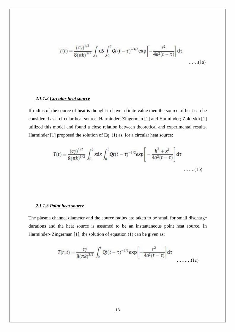
2.1.1.1 Plane heat source
If the source of heat is assumed to have infinitely long radius, heat flow statement can be
summarised to a single-dimension problem. Solution to the equation (1) is, as given in [1]:
13
……(1a)
2.1.1.2 Circular heat source
If radius of the source of heat is thought to have a finite value then the source of heat can be
considered as a circular heat source. Harminder; Zingerman [1] and Harminder; Zolotykh [1]
utilized this model and found a close relation between theoretical and experimental results.
Harminder [1] proposed the solution of Eq. (1) as, for a circular heat source:
…….(1b)
2.1.1.3 Point heat source
The plasma channel diameter and the source radius are taken to be small for small discharge
durations and the heat source is assumed to be an instantaneous point heat source. In
Harminder- Zingerman [1], the solution of equation (1) can be given as:
………(1c)
14
2.1.2 Thermal stress model
The extreme temperature gradients which occur during electrical discharge machining, as
discussed in [19], results in very large non uniformities during the thermal expansion of
workpiece material locally,(known as strain) which leads to very large thermal stresses.
Temperature distribution in workpiece which is transient can be obtained by solving the
equation of heat conduction also with initial and boundary conditions which are used as input
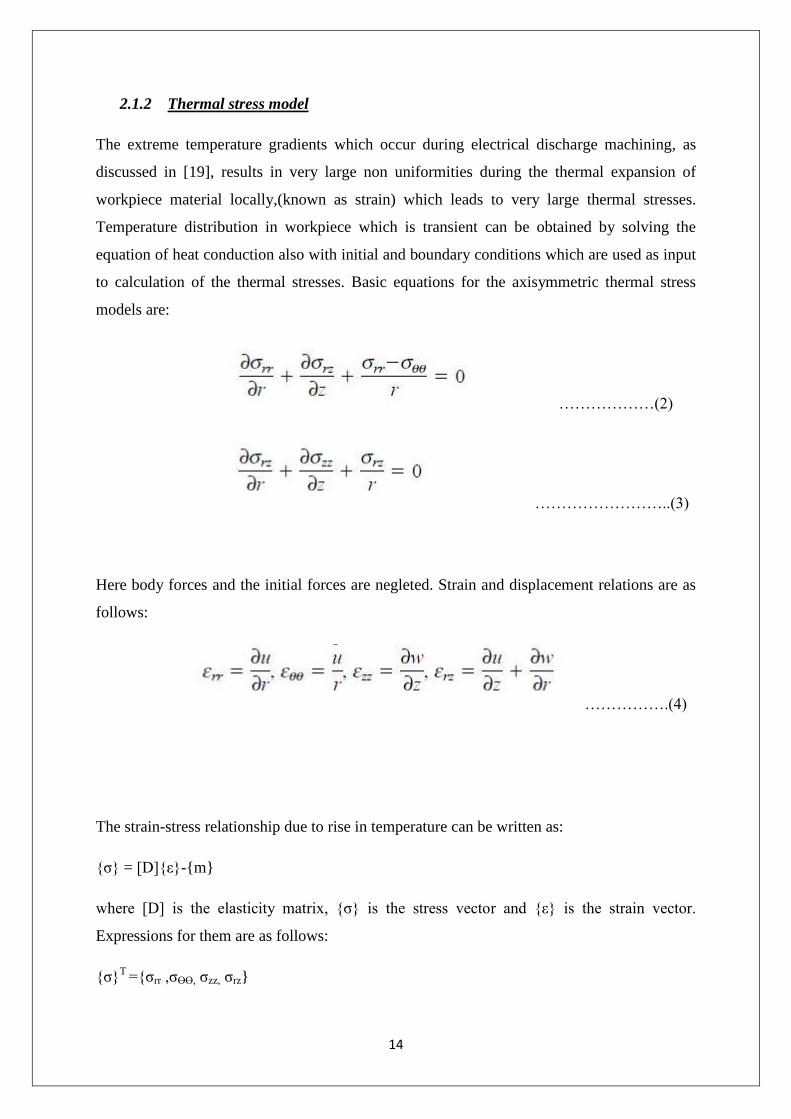
to calculation of the thermal stresses. Basic equations for the axisymmetric thermal stress
models are:
………………(2)
……………………..(3)
Here body forces and the initial forces are negleted. Strain and displacement relations are as
follows:
…………….(4)
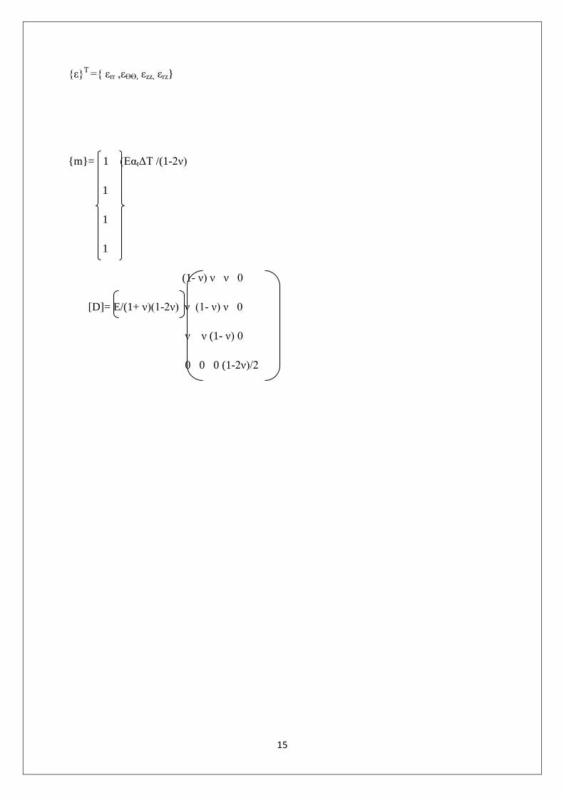
The strain-stress relationship due to rise in temperature can be written as:
{ζ} = [D]{ε}-{m}
where [D] is the elasticity matrix, {ζ} is the stress vector and {ε} is the strain vector.
Expressions for them are as follows:
{ζ}T ={ζrr ,ζϴϴ, ζzz, ζrz}
15
{ε}T ={ εrr ,εϴϴ, εzz, εrz}
{m}= 1 (EαtΔT /(1-2ν)
1
1
1
(1- ν) ν ν 0
[D]= E/(1+ ν)(1-2ν) ν (1- ν) ν 0
ν ν (1- ν) 0
0 0 0 (1-2ν)/2

16
2.2 Electrical Discharge Machined surface integrity
2.2.1 Metallurgical characteristics of the EDM’ed surface
[21] The structural progressions of electro discharge machined surfaces were studied. For the
tool steels, it is demonstrated, from different examiners, the upper-most layer of the surface is
a non-etchable layer and uneven, specifically called the 'white layer'. It is a re-cast layer
structured by the molten metal getting solidified at a very high rate after the discharge
procedure is finished. Underneath the 'white layer' there is a halfway intermediate layer, a
high temperature-influenced region, where heat is not sufficiently high enough to cause
melting however it is high enough to affect the micro-structural changes in the material. Re-
cast layer was found to be intensely alloyed with pyrolysis remnants of the cracked dielectric
material. When the tool electrode, let's take copper, for instance, is perfectly compatible,
surface alloying can be likewise found. Along with the compatible reagents, it is shown that,
contingent upon the machinability conditions and on the steel, a diverse micro-structures of
it, can come about.
Many an authors have described that the spark-affected layer could be different if they were
machined by copper or graphite electrodes; dendritic austenite and a cementite–austenite
eutectic or a fully austenitic surface followed by an austenite–cementite matrix, respectively.
Same structure of carbides in the austenitic matrix have been described by some other
authors, but it was stated that for a variety of electrodes it would not change the structure of
white layer but the ratio of the carbide and the austenitic phases would vary. Increase in
carbon content in the sub-surface layers and surface layers as a result of electro discharge
machining has been pointed out by many a researchers to the pyrolysis of dielectric, and
others have suggested that the carbon is assimilated more rapidly from the graphite electrodes
than from the carbonaceous dielectric.

17
Figure 2 Micro crack formation on EDM sample [20]
Residual stresses are generated in EDM, due to metallurgical transformations and non-
homogeneity of the heat flow. Research for the residual stresses of EDMed surfaces has
revealed the tensile behaviour, and their high values at the surface layers, the narrowness of
the superficial zone where they appear, and the increment of their value with the increment of
pulse energy.
[20] A thick multi layer which is made up of two or three single layer type recast layers
which overlap each other is formed as a result of the molten metal which oozes onto an
existing recast layer and finally gets solidified. A very thin featureless layer can be very
lightly identified on the surface and also between the overlapped recast layers. A relatively
thick featureless layer which separates the base material and heat affected zone indicates that
any coring effect in these layers is negligible. Also changes in depths of the featureless
layers, suggests that molten metal is solidified at the centre of the melt where temperature
gradient is much higher than on the surface. Voids were found to start from a point which
was on the interfacial line of the overlapped recast layers. Also tiny amount of gas was
trapped under the ridges of the craters by the action of expelled molten material while the
discharging process took place. This gas that was trapped would formulate a bubble and

18
would expand until it instantly freezes due to the high cooling rates during solidification
process.
Figure 3 SEM micrographs of EDMed surfaces [20]
2.2.2 Residual stresses and Thermal Stresses
[4] These are self-equilibrating stresses that exist in structures under the uniform temperature
conditions without any foreign loads. These stresses are produced if the regions of structures
are non-homogeneous and plastically deformed in a permanent manner such that the strain
incompatibilities would occur. Residual stresses are classified into three categories as per the
distance over where they are equilibrated. They are the residual stresses of the 1st, 2
nd and 3
rd
kind.
19
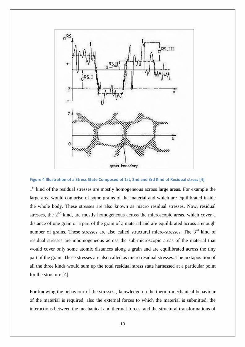
Figure 4 Illustration of a Stress State Composed of 1st, 2nd and 3rd Kind of Residual stress [4]
1st kind of the residual stresses are mostly homogeneous across large areas. For example the
large area would comprise of some grains of the material and which are equilibrated inside
the whole body. These stresses are also known as macro residual stresses. Now, residual
stresses, the 2nd
kind, are mostly homogeneous across the microscopic areas, which cover a
distance of one grain or a part of the grain of a material and are equilibrated across a enough
number of grains. These stresses are also called structural micro-stresses. The 3rd
kind of
residual stresses are inhomogeneous across the sub-microscopic areas of the material that
would cover only some atomic distances along a grain and are equilibrated across the tiny
part of the grain. These stresses are also called as micro residual stresses. The juxtaposition of
all the three kinds would sum up the total residual stress state harnessed at a particular point
for the structure [4].
For knowing the behaviour of the stresses , knowledge on the thermo-mechanical behaviour
of the material is required, also the external forces to which the material is submitted, the
interactions between the mechanical and thermal forces, and the structural transformations of
20
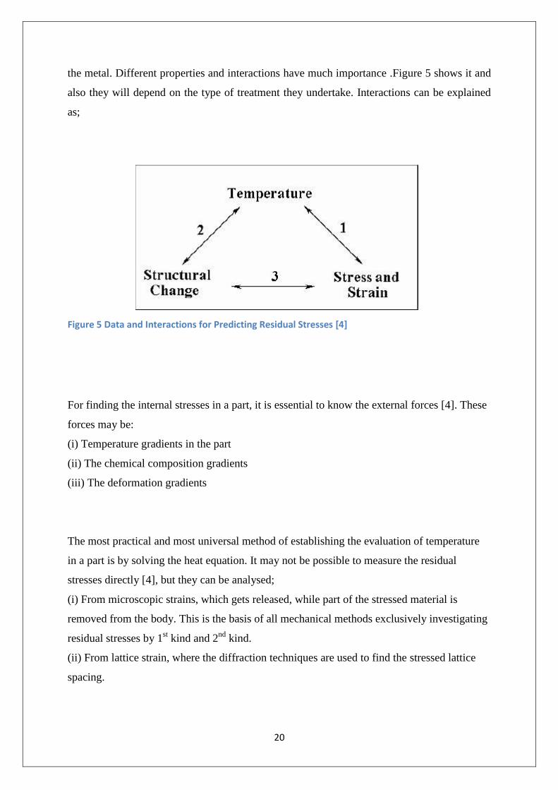
the metal. Different properties and interactions have much importance .Figure 5 shows it and
also they will depend on the type of treatment they undertake. Interactions can be explained
as;
Figure 5 Data and Interactions for Predicting Residual Stresses [4]
For finding the internal stresses in a part, it is essential to know the external forces [4]. These
forces may be:
(i) Temperature gradients in the part
(ii) The chemical composition gradients
(iii) The deformation gradients
The most practical and most universal method of establishing the evaluation of temperature
in a part is by solving the heat equation. It may not be possible to measure the residual
stresses directly [4], but they can be analysed;
(i) From microscopic strains, which gets released, while part of the stressed material is
removed from the body. This is the basis of all mechanical methods exclusively investigating
residual stresses by 1st kind and 2
nd kind.
(ii) From lattice strain, where the diffraction techniques are used to find the stressed lattice
spacing.
21
(iii) From propagation velocities of birefringence of ultrasonic waves influenced by the
residual stresses
(iv) From the magnetic properties and phenomena of the material that is influenced by all
kinds of residual stresses.
The most useful mechanical techniques are as follows,
(i) Hole drilling method
(ii) Ring core technique
(iii) Layer method
(iv) Sectioning method
For the residual stress determinations the hole drilling or the ring core method are used,
where strains in the vicinity of the hole due to semi release of residual stresses will be
identified. And from those values and by usage of Poisson’s ratio and Young’s modulus and
also the calibration coefficients of the material, the residual stresses can be measured by
applying strain gauge configurations.
The concept behind layer removal method is the balancing of internal moments and stresses
when the residual stresses are slowly relaxed from the material by subsequent thin layers
using chemical machining or ECM. Resultant strains and deflections due to equilibrium of
internal stresses are calculated to find residual stresses from the elasticity theory. In general,
residual stresses in the outermost surface layers of the components cannot be measured
easily.
If the sectioning technique is used, the equilibrium conditions for stresses and moments will
be considered. The object is cut in section and the stress is relaxed. The averaged strain
values are identified as per the bulk of the removed material, which determines the bulk of
stress that is released. Residual stress values are analysed by any mechanical method can be
contradicted with plasticity effects when very high quantities of stress would exist. Strong
residual stress gradients and improper sectioning underneath the surface also may lead to
some uncertainties in the results.
22
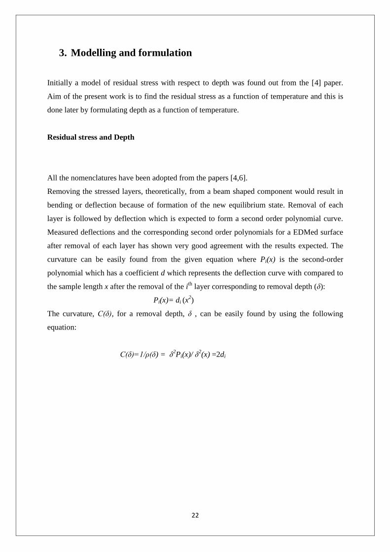
3. Modelling and formulation
Initially a model of residual stress with respect to depth was found out from the [4] paper.
Aim of the present work is to find the residual stress as a function of temperature and this is
done later by formulating depth as a function of temperature.
Residual stress and Depth
All the nomenclatures have been adopted from the papers [4,6].
Removing the stressed layers, theoretically, from a beam shaped component would result in
bending or deflection because of formation of the new equilibrium state. Removal of each
layer is followed by deflection which is expected to form a second order polynomial curve.
Measured deflections and the corresponding second order polynomials for a EDMed surface
after removal of each layer has shown very good agreement with the results expected. The
curvature can be easily found from the given equation where Pi(x) is the second-order
polynomial which has a coefficient d which represents the deflection curve with compared to
the sample length x after the removal of the ith
layer corresponding to removal depth (δ):
Pi(x)= di (x2)
The curvature, C(δ), for a removal depth, δ , can be easily found by using the following
equation:
C(δ)=1/ρ(δ) = δ2Pi(x)/ δ
2(x) =2di

23
Figure 6 Deflection of sample due to layer removal [6]
To find the curvature, the ratio of the measured average removed layer depth, δ, to the initial
sample depth or thickness, H, is defined as dimensionless thickness δ*, and a dimensionless
curvature C*(δ), which is represented as;
δ*= δ/H
and, C*(δ)=H. C(δ)
The dependence of the variables, relationally is found as a special form of Gaussian
distribution, which is the sum of two Gaussian peaks, with the same amplitude and the pulse
width but with opposite center location. Relation can be expressed in the following form:
C*(δ)=a1cosh(a2δ*)exp(-(a3δ*)2)
a1, a2 and a3 are found from empirical relations [4,6] and there values are given as 0.0003653,
53.33, and 43.89 respectively.

24
Aggregate energy supplied for a single spark can be written as:
Et=IavUavtp
It would be more realistic to use the aggregate energy received by the workpiece during
machining. But, many a investigators have assumed that some constant fraction of total
power is goes to electrodes. The energy fraction to cathode be Rw, which is usually taken as
0.08. So, the total amount of energy harnessed by the workpiece due to single discharge can
be shown as:
Ew = RwIavUavtp
Thermo-physical properties of the material should also be included, hence Ew becomes Ew*,
which is dimensionless and it is given as;
Ew*= Ew [(ρ5c
9)/(k
8α)]
1/3
A new parameter g*is defined in order to scale the constant coefficients a1, a2, and a3.
Henceforth we can obtain the coefficients for different pulse energies by using g*.Hence
scaling factor g* which is dimensionless is found to be dependent on the dimensionless
energy for a single spark as follows:
g*=204.5*10-6
(Ew*)0.38

25
Finally the generalized and proposed form of curvature dependent on a1, a2,
a3, and g* can be expressed as:
C*(δ)=A1cosh(A2δ*)exp(-(A3δ*)2)
Where A1=a1g*, A2=a2 /g* and A3=a3 /g*.
And now, when the proposed empirical relation is inserted into the dimensionless form of
Stablein equation [4,6] we have;
…….(5)
The result is the residual stress profile as a function of depth caused by EDM. Constants A1,
A2, and A3 are the empirical coefficients found erstwhile.
Depth and temperature
Now, the proposed equation gives the residual stress profile with respect to depth. But the
aim of finding residual stress with respect to temperature is still to be founded. The
assumptions taken in the model given in [5] are;
Model developed is for single spark
Workpiece considered as a semi-infinite body
Thermal effects of successive sparks on each other are neglected
Phase changes are neglected during analysis
Crater formed on workpiece due to each discharge is assumed to be circular parabolic

26
Redeposit of recast layer in the crater after each spark is considered to be uniform.
Hence, now depth as a function of temperature is formulated from a data given in [5];
Figure 7 Temperature distribution along depth of workpiece at centreline discharge position [5]
Figure 8 A zone in fig 5 from [5]
27
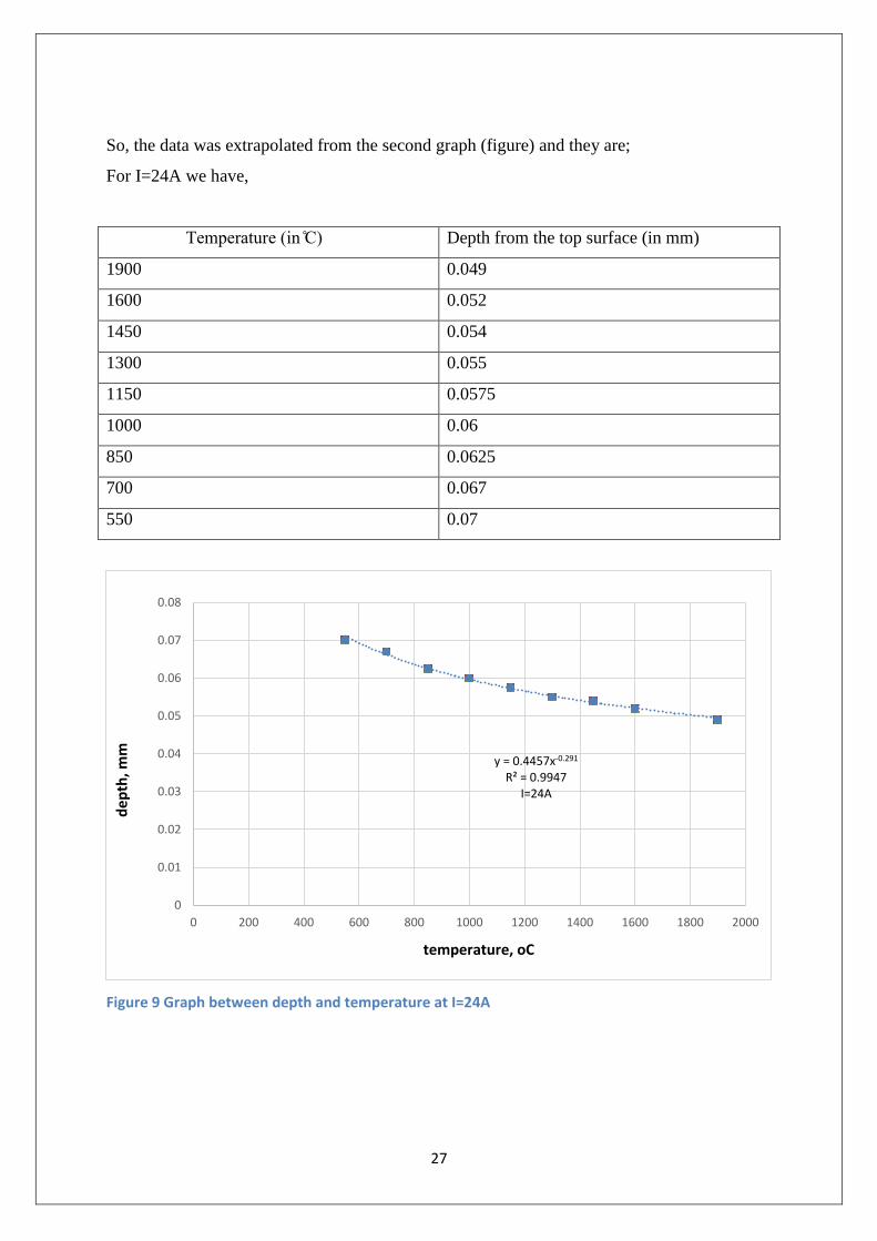
So, the data was extrapolated from the second graph (figure) and they are;
For I=24A we have,
Temperature (in ) Depth from the top surface (in mm)
1900 0.049
1600 0.052
1450 0.054
1300 0.055
1150 0.0575
1000 0.06
850 0.0625
700 0.067
550 0.07
Figure 9 Graph between depth and temperature at I=24A
y = 0.4457x-0.291 R² = 0.9947
I=24A
0
0.01
0.02
0.03
0.04
0.05
0.06
0.07
0.08
0 200 400 600 800 1000 1200 1400 1600 1800 2000
temperature, οC
dep
th, m
m
28
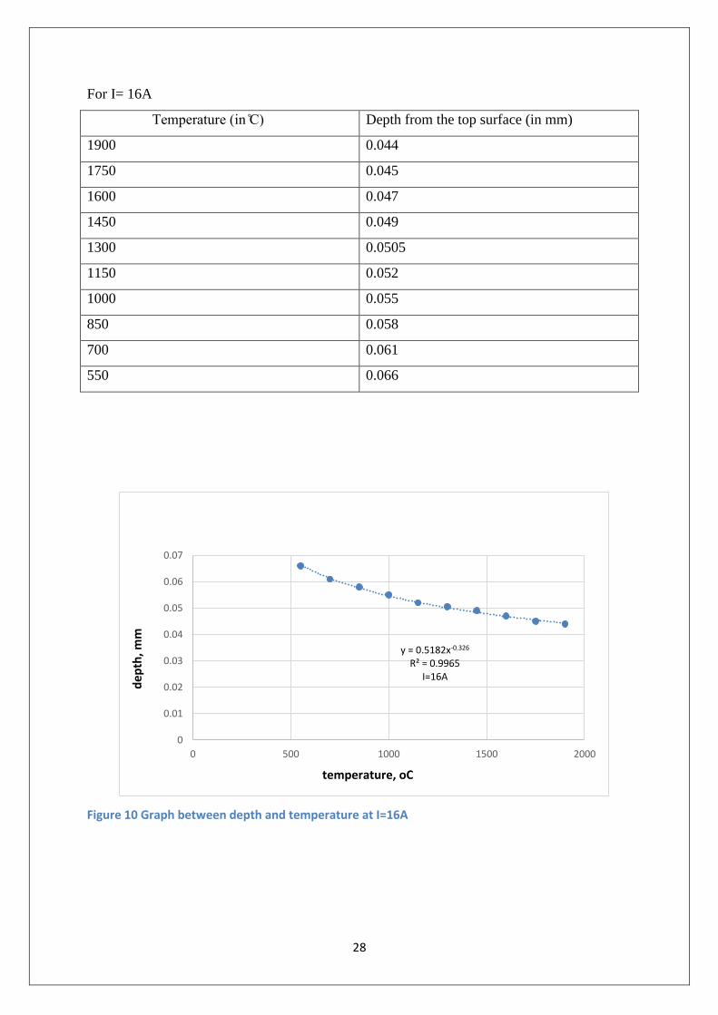
For I= 16A
Temperature (in ) Depth from the top surface (in mm)
1900 0.044
1750 0.045
1600 0.047
1450 0.049
1300 0.0505
1150 0.052
1000 0.055
850 0.058
700 0.061
550 0.066
Figure 10 Graph between depth and temperature at I=16A
y = 0.5182x-0.326 R² = 0.9965
I=16A
0
0.01
0.02
0.03
0.04
0.05
0.06
0.07
0 500 1000 1500 2000
temperature, οC
dep
th, m
m

29
For I=8A, we have,
Temperature (in ) Depth from the top surface (in mm)
1750 0.037
1600 0.0385
1450 0.04
1300 0.043
1150 0.0445
1000 0.048
850 0.0508
700 0.055
550 0.0595
Figure 11 Graph between depth and temperature at I=8A
y = 0.8439x-0.418 R² = 0.9945
I=8A
0
0.01
0.02
0.03
0.04
0.05
0.06
0.07
0 500 1000 1500 2000
z
temperature, οC
dep
th, m
m
30
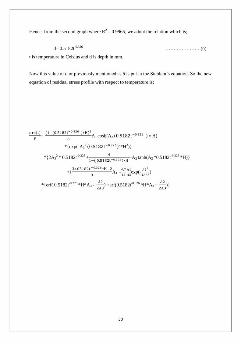
Hence, from the second graph where R2
= 0.9965, we adopt the relation which is;
d= 0.5182t-0.326
………………….(6)
t is temperature in Celsius and d is depth in mm.
Now this value of d or previously mentioned as δ is put in the Stablein’s equation. So the new
equation of residual stress profile with respect to temperature is;
( )
=
( ( ) )
A1 cosh(A2 ( ) )
*{exp(-A32 ( )2
*H2)}
*{2A32
* 0.5182t-0.326
+
( ) –A2 tanh(A2 *0.5182t
-0.326 *H)}
+{
A1 -
exp(-
)
*{erf( 0.5182t-0.326
*H*A3 -
) +erf(0.5182t
-0.326 *H*A3 +
)}

31
4. Validation of proposed relationship
The relationship between depth and temperature is validated by plotting a curve for another
set of data [8].
Temperature, (in ) Depth calculated
(d= 0.5182t-0.326
),in mm, z
Depth extrapolated, in mm,
z’
504.6 .0681 .072
727 .0604 .0586
837.96 .0577 .0536
1060.33 .0535 .051
1282.4 .0502 .047
1504.62 .0477 .045
1727 .0456 .041
Figure 12 Validation of empirical relation
0
0.01
0.02
0.03
0.04
0.05
0.06
0.07
0.08
0 500 1000 1500 2000
De
pth
,mm
Temperature, ̊C
z
z'

32
The graph shows the relational dependence of depth and temperature. Values of depth were
calculated from the empirical relation, eq. (6). These values are very closely predicted with
respect to the actual values found from extrapolation of the depth values in [8]. The blue
curve is the empirical relation and the red one consists of actual values. Thus, most of the
points almost coincide with each other. The difference occurs because the experimental
conditions in the red curve are different from the one empirical relation was found. Value of
current in it is 20A and Ton is 500 seconds. Hence, the little variations occur which are well
under the tolerance limit. So, the empirical relation is validated with this new data.
Both the values are from simulated models, as actual experiment has not been carried out.
Hence, a large amount of future scope is there in this regard, for validating the models
experimentally.

33
5. Conclusion
The present work aims at establishing the relationship between temperature during EDM and
the residual/ thermal stress generated. Following conclusions may be drawn from the current
study:
1. Various thermal models have been studied in order to understand the correlation
between depth of surface affected by EDM operation and the temperature and residual
stress. The residual stress would rapidly increase compared to depth and reaches its
maximum value within the heat-affected region.
2. The temperature has an exponential (empirical) relation with the depth. This relation
is further used to connect the residual stress with the temperature and having the depth
as an intermediate function which was eliminated later.
3. The graphs in figure 11,10 and 9 are compared extensively. The graph between depth
and temperature for I=8A is the steepest and this implies that the value of temperature
increases very rapidly with decrement of depth with respect to the other two curves.
4. The graph between depth and temperature for I=16A stays in between in the field of
steepness. Also the curve for I=24A is the flattest and hence the temperature variation
is not so rapid compared to other two.
5. So, it can be deduced as the average value of current increases the decrement of
temperature with respect to depth is slower compared to the rate of decrement for
lower values of current.

34
6. References
1. Harminder Singh, Experimental study of distribution of energy during EDM
process for utilization in thermal models, International Journal of Heat and Mass
Transfer, 2012
2. S. Hinduja, M. Kunieda; Modelling of ECM and EDM processes, CIRP Annals -
Manufacturing Technology, 2013
3. PANKAJ KUMAR SONI,RAJU GHOLLEY; STUDY AND ANALYSIS OF RESIDUAL
STRESSES IN ELECTRO-DISCHARGE MACHINING (EDM), E-thesis, NIT RKL, 2007
4. Bülent Ekmekci , Oktay Elkoca , A. Erman Tekkaya ,Abdulkadir Erden; RESIDUAL
STRESS STATE AND HARDNESS DEPTH IN ELECTRIC DISCHARGE MACHINING:
DE-IONIZED WATER AS DIELECTRIC LIQUID, Machining Science and
Technology: An International Journal, 2005
5. M R Shabgard, A numerical method for predicting depth of heat affected zone in
EDM process for AISI H13 tool steel, Journal of Scientific and Industrial Research,
2011
6. Bülent ekmekç, Theoretical and experimental investigation of residual stresses
in electric discharge machining, a thesis submitted to the graduate school of
natural and applied sciences of the middle east technical university, 2004
7. P. Shankar, V. K. Jain; Analysis of spark profiles during edm process, Machining
Science and Technology: An International Journal, 2007
8. Mehrdad Hosseini Kalajahi, Experimental and finite element analysis of EDM
process and investigation of material removal rate by response surface
methodology, Int J Adv Manuf Technol (2013)
9. S. Keith Hargrove; Determining cutting parameters in wire EDM based on
workpiece surface temperature distribution, Int J Adv Manuf Technol, 2007
10. E. Weingärtner, Modeling and simulation of electrical discharge machining, 1st
CIRP Global Web Conference: Interdisciplinary Research in Production
Engineering, 2012
11. Chinmaya P. Mohanty, Thermal-structural Analysis of Electrical Discharge
Machining Process, Chemical, Civil and Mechanical Engineering Tracks of 3rd
Nirma University International Conference on Engineering (NUiCONE 2012)
12. S.N. Joshi, S.S. Pande, Thermo-physical modeling of die-sinking EDM process,
Journal of Manufacturing Processes, 2010

35
13. J.W. Murray, A.T. Clare, Repair of EDM induced surface cracks by pulsed electron
beam irradiation, Journal of Materials Processing Technology, 2012
14. Shuvra Das , Mathias Klotz, EDM simulation: finite element-based calculation of
deformation, microstructure and residual stresses, Journal of Materials
Processing Technology, 2003
15. Y.H. Guu, Max Ti-Kuang Hou, Effect of machining parameters on surface textures
in EDM of Fe-Mn-Al alloy, Materials Science and Engineering, 2007
16. Mohammadreza Shabgard, Mathematical and numerical modeling of the effect of
input-parameters on the flushing efficiency of plasma channel in EDM process,
International Journal of Machine Tools & Manufacture, 2012
17. Bu¨lent Ekmekci, A semi-empirical approach for residual stresses in electric
18. discharge machining (EDM), International Journal of Machine Tools &
Manufacture, 2005
19. Vinod Yadav, Thermal stresses due to electrical discharge machining,
International Journal of Machine Tools & Manufacture, 2002
20. Bu¨lent Ekmekci, Residual stresses and white layer in electric discharge
machining (EDM), Applied Surface Science, 2007
21. J.C. Rebelo, Influence of EDM pulse energy on the surface integrity of martensitic
steels, Journal of Materials Processing Technology, 1997