Modelling of Multi-Megawatt Wind Turbines for EMI …2167).pdf · Modelling of Multi-Megawatt Wind...
4
32 nd URSI GASS, Montreal, 19-26 August 2017 Modelling of Multi-Megawatt Wind Turbines for EMI and EMS Investigations by a Topological Approach Sven Fisahn, Sebastian Koj*, Heyno Garbe Institute of Electrical Engineering and Measurement Technology, Leibniz Universität Hannover, Hanover, Germany, http://www.geml.uni-hannover.de Abstract Todays installed multi-megawatt wind turbines (WT) form highly diverse system due to very complex control devices. Thus, special attention has to be paid to the electromagnetic compatibility (EMC) of the wind turbine. This contribution deals with different electromagnetic interference (EMI) and susceptibility (EMS) effects within the wind turbine. A well-known susceptibility problem of constructions and buildings with large vertical dimensions is the threat situation due to lightning phenomena. On the one hand, the high amplitude of the lightning current effects destructions of infrastructure directly. On the other hand, the transient electromagnetic fields caused by this lightning current could lead to disturbances as well as destructions of electronic devices inside the wind turbine. Furthermore, common-mode currents ܫ on the power lines between the generator and the frequency converter will cause EMI effects during the normal operation mode. These ܫ s lead to radiated emissions to the WT´s environment as well as to transient disturbing fields inside the WT, which might interfere with the control unit (CU) and the condition monitoring system (CMS). These issues will be investigated in this contribution. Therefore, the electromagnetic topology (EMT) will be applied to the wind turbine. The EMT delivers useful information in order to increase the WT´s susceptibility and ensure a high degree of availability. 1. Introduction Because of the politically declared goal of promoting the regenerative energy sources and increasing their contribution of the total energy supply significantly, especially wind turbines (WTs) have experienced a rapid development in recent decades. In addition to the expansion of locations - both onshore and offshore - the development is characterized by a constant increase in the dimensions of WTs (hub height, rotor diameters) and a continuous increase in the performance up to several megawatts today. The financial value concentration associated with the performance increase leads to the desire to improve the availability of the WT and to minimize the downtime by inadvertent failures of the partial components. This is possible by the planned and targeted maintenance of the WT components, provided the condition of the fatigue of the partial component is known. In order to monitor the condition of the critical components, so-called Condition Monitoring Systems (CMS) are used, which consists of various sensors distributed over the entire plant, as well as measuring and control units (CUs). In order to ensure a qualified monitoring and condition-oriented response in case of need, the electromagnetic compatibility (EMC) in the WT must be also ensured for the components of the CMS. For this purpose, the method of electromagnetic topology (EMT) is presented and explained in chapter two. In chapter three follows an exemplary application of the EMT to a WT considering the lightning protection system and the critical components of a wind turbine. In chapter four, EMI sources inside the WT are identified and analyzed. Furthermore, measurement results of the common-mode current ܫ on the power line between generator and frequency converter are presented and the related EMI aspects are discussed. The findings obtained are finally used to supplement the topological model of a WT. 2. Electromagnetic Topology (EMT) The zone concept is a powerful method for the analysis of complex EMC problems and the deriving of appropriate countermeasures. A typical EMS application of this method for example is in the working field of lightning protection and has already found its way into the international standard IEC 62305-4 [6]. Nevertheless, the zone concept in general is not only limited to the lightning protection zone (LPZ) concept or other EMS problems, but also well suited for the treatment of many other EMC measures like EMI problems. Its formal description is called electromagnetic topology (EMT) [2, 3]. For this issue, the EMC problem is described qualitatively in a first step. Therefore, the space occupied by the system is divided into individual volumes which are surrounded by surfaces (volume/surface topology). Furthermore, the interactions between these volumes are described by an interaction graph (interaction sequence diagram). Both, the volume/surface topology as well as the interaction sequence diagram form the so called topological model of the system to be analyzed, as shown exemplarily in Fig. 1. For a precise topological model the following distinctions are important: Firstly, the surfaces can be divided into proper surfaces, which have a high level of shielding effectiveness (SE) e.g. metallic surfaces, and elementary surfaces without respectively only a low level of SE. The first type of surface is illustrated in Fig. 1 by a solid line, the second one by a dashed line. This distinction allows the
Transcript of Modelling of Multi-Megawatt Wind Turbines for EMI …2167).pdf · Modelling of Multi-Megawatt Wind...
32nd URSI GASS, Montreal, 19-26 August 2017
Modelling of Multi-Megawatt Wind Turbines for EMI and EMS Investigations
by a Topological Approach
Sven Fisahn, Sebastian Koj*, Heyno Garbe
Institute of Electrical Engineering and Measurement Technology, Leibniz Universität Hannover, Hanover, Germany, http://www.geml.uni-hannover.de
Abstract Todays installed multi-megawatt wind turbines (WT) form highly diverse system due to very complex control devices. Thus, special attention has to be paid to the electromagnetic compatibility (EMC) of the wind turbine. This contribution deals with different electromagnetic interference (EMI) and susceptibility (EMS) effects within the wind turbine. A well-known susceptibility problem of constructions and buildings with large vertical dimensions is the threat situation due to lightning phenomena. On the one hand, the high amplitude of the lightning current effects destructions of infrastructure directly. On the other hand, the transient electromagnetic fields caused by this lightning current could lead to disturbances as well as destructions of electronic devices inside the wind turbine. Furthermore, common-mode currents on the power lines between the generator and the frequency converter will cause EMI effects during the normal operation mode. These s lead to radiated emissions to the WT´s environment as well as to transient disturbing fields inside the WT, which might interfere with the control unit (CU) and the condition monitoring system (CMS). These issues will be investigated in this contribution. Therefore, the electromagnetic topology (EMT) will be applied to the wind turbine. The EMT delivers useful information in order to increase the WT´s susceptibility and ensure a high degree of availability. 1. Introduction Because of the politically declared goal of promoting the regenerative energy sources and increasing their contribution of the total energy supply significantly, especially wind turbines (WTs) have experienced a rapid development in recent decades. In addition to the expansion of locations - both onshore and offshore - the development is characterized by a constant increase in the dimensions of WTs (hub height, rotor diameters) and a continuous increase in the performance up to several megawatts today. The financial value concentration associated with the performance increase leads to the desire to improve the availability of the WT and to minimize the downtime by inadvertent failures of the partial components. This is possible by the planned and targeted maintenance of the WT components, provided the condition of the fatigue of the partial component is known. In order to monitor the condition of the critical
components, so-called Condition Monitoring Systems (CMS) are used, which consists of various sensors distributed over the entire plant, as well as measuring and control units (CUs). In order to ensure a qualified monitoring and condition-oriented response in case of need, the electromagnetic compatibility (EMC) in the WT must be also ensured for the components of the CMS. For this purpose, the method of electromagnetic topology (EMT) is presented and explained in chapter two. In chapter three follows an exemplary application of the EMT to a WT considering the lightning protection system and the critical components of a wind turbine. In chapter four, EMI sources inside the WT are identified and analyzed. Furthermore, measurement results of the common-mode current on the power line between generator and frequency converter are presented and the related EMI aspects are discussed. The findings obtained are finally used to supplement the topological model of a WT. 2. Electromagnetic Topology (EMT) The zone concept is a powerful method for the analysis of complex EMC problems and the deriving of appropriate countermeasures. A typical EMS application of this method for example is in the working field of lightning protection and has already found its way into the international standard IEC 62305-4 [6]. Nevertheless, the zone concept in general is not only limited to the lightning protection zone (LPZ) concept or other EMS problems, but also well suited for the treatment of many other EMC measures like EMI problems. Its formal description is called electromagnetic topology (EMT) [2, 3]. For this issue, the EMC problem is described qualitatively in a first step. Therefore, the space occupied by the system is divided into individual volumes which are surrounded by surfaces (volume/surface topology). Furthermore, the interactions between these volumes are described by an interaction graph (interaction sequence diagram). Both, the volume/surface topology as well as the interaction sequence diagram form the so called topological model of the system to be analyzed, as shown exemplarily in Fig. 1. For a precise topological model the following distinctions are important: Firstly, the surfaces can be divided into proper surfaces, which have a high level of shielding effectiveness (SE) e.g. metallic surfaces, and elementary surfaces without respectively only a low level of SE. The first type of surface is illustrated in Fig. 1 by a solid line, the second one by a dashed line. This distinction allows the

implementation of a shielding order, e. g. the volume , has the shielding order 0, whereas , has the shielding order 3, since it is surrounded by three completely closed proper surfaces. Secondly, it is sensible to differ conducted interactions and radiated interactions (illustrated by red respectively blue lines). While the radiated interactions penetrate elementary surfaces nearly undamped, they will be attenuated by proper surfaces significantly and can only overcome this barrier by coupling through apertures (blue ellipses in Fig. 1).
Figure 1. Topological model of a complex system (volume/surface topology and corresponding interaction sequence diagram)
After setting up the topological model, the graph can be transferred into a general matrix equation, which is a form of the Baum-Liu-Tesche (BLT) equation. Since the EMT is a very powerful methodology and suited for the analysis as well as for the design of complex electric and electronic systems, it is sufficient in most cases to use only the qualitative description (volume/surface topology and related interaction graph) in order to estimate the reliability of an electronic system against electromagnetic interferences (EMI). 3. EMT applied to Wind Turbines After the theory of the EMT has been explained, its application to a WT is discussed below. Here, existing work from the working field of lightning protection is used, where the EMT is known as the LPZ concept [7, 8, 9]. Figure 2 shows a possible segmentation of WT into different LPZs. In the outer region around the WT, a distinction is made between LPZ 0A and LPZ 0B. Zone LPZ 0A is assigned to system components, which are exposed to a direct lightning strike. On the other hand, the LPZ 0B zone encloses those parts of the system, which are protected from direct lightning strikes by external air-termination, or other parts of the system. Nevertheless, in both zones strong and unattenuated electromagnetic fields of the lightning must be expected. Both LPZ 0A and LPZ 0B can be determined by the so-called rolling sphere method. According to [7] this method is not applicable to the rotor blades. Furthermore, the protection class I must be applied in accordance with [3, 4, 5]. The towers of a nowadays installed WTs are often realized as a solid metal tower or concrete metal tower. Due to this
construction, the attenuation of the lightning-induced electromagnetic fields is achieved inside the tower. Thus, the volume enclosed by the tower wall is defined as LPZ 1.Similarly, a second LPZ 1 is surrounded from the nacelle, since the most frequently installed nacelles are made of metal or glass fiber reinforced plastic (GRP) with metal mesh. Higher order LPZs can be achieved by using metallic enclosures and housings within the WT. Conceivable in this case are cabinets for the control systems of the frequency inverter, for the control of the generator and the housing in the hub for the control of the drive systems for adjusting the blade position. In order to protect the devices in the respective LPZ against the effects of the lightning current, appropriate surge protection devices (SPDs) must be provided.
Figure 2. Segmentation of a WT into different LPZs
Due to this zoning, the electrical and electronic equipment installed in the WT can be arranged according to the shielding effect, yet. In the LPZ concept, the zones are determined with respect to the expected EMC climate, whereby the lightning strike is assumed to be the largest and the only EMI disturbance source, which disturbing effects decrease from the outside of the system to its inside. In complex systems, such as today's WT with various CMS components, also the EMI sources occurring in WT must be taken into account. This is discussed in the following chapter. 4. Internal EMI Sourses 4.1 Source Identifikation As the largest internal EMI sources inside a WT, the generator due to the large induced currents and the frequency converter due to the steep edges of the switched

voltages can be identified. These two EMI sources are normally installed in metallic housings, which attenuate the interference effects if the grounding system is correctly implemented. Thus, the volumes, which include the frequency converter and the generator, can be declared as separated zones. A further potential EMI source may represent the power line between the generator and frequency converter. In contrast to the two previously mentioned EMI sources, the power line extends over the entire height of the WT - in plants installed nowadays not infrequently more than one hundred meters. The propagating along the power line can also lead to disturbances inside the WKA as well as outside the system. Exemplary measuring results of the are presented below. 4.2 Common-mode current measurement
Table 1. Characteristics of the examined test WT
Nominal power level 240 kW Tower height 50 m Total height 65 m Tower material steel Type of generator synchronous generator
In order to prove the on the power line between the generator and the frequency converter, the power on and shutdown processes of a test WT characterized in Table 1 are analyzed in a metrological manner. The was measured in the ground floor of the plant in the frequency range from 150 kHz to 30 MHz using a current clamp and an EMI-receiver. Fig. 3 shows a spectrogram of the measured during the power on process. The measurement started at the time = 0 and takes about 40 seconds with a resolution time of 100 ms. At = 1 s, the system is connected to the grid by closing the contactor. The resulting pulse can be detected between 150 kHz and 5 MHz. At = 28 s the converter starts to operate and a change of the amplitudes of the can be noticed in the observed frequency range, especially from 150 kHz to approx. 10 MHz. In the further course, no appreciable changes of the amplitudes can be observed. Fig. 4 shows the spectrogram of a shutdown process of the test WT. At the beginning of this measurement ( = 0), the system is still in operation. The shutdown process of the system was initiated at approx. = 7 s. It can be noticed that the some spectral components of the drops at this time. The reason for this is the adjustment of the rotor blades and the slowing down of the rotational speed of the rotor. At the time = 14 s, the frequency converter is switched off. A significant reduction in the amplitudes of the can be seen in the entire frequency range. At = 16 s, the system is disconnected from the grid by opening the contactor. The resulting pulse can be detected in the entire frequency range. Both spectrograms show that the spectrum of the remains approximately constant during operation and have a maximum of about 90 dBµA. Further measurement results of on the power line in a WT are shown in [10].
Figure 3. Power on process of a test WT
Figure 4. Shutdown process of a test WT
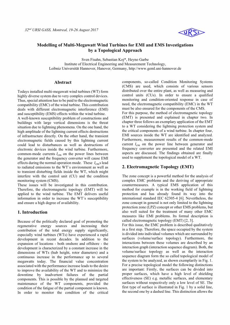
4.3. Consequences for the EMT-Model In chapter 3, the EMT was applied to a wind turbine with a solid metal respectively a concrete metal tower. Therefore, the WT was segmented into different LPZs according to the international standard IEC 62305-4 (see Fig. 2). The major lack of this LPZ concept is, that it takes only a lightning strike as a source for EMC problems into account. Since the was identified as a seconds disturbing source by the measurements presented in section 4.2, it seems to be reasonable to extent the classic LPZ model. In figure 5, the surrounding environment of the power line between the generator and frequency converter is modeled as an additional zone, because the on the powerline effects disturbing electromagnetic field in this region. Furthermore, the nomenclature is aligned to the one presented in chapter 2 in order to avoid confusions with the LPZ model. The additional zone mentioned above is named , . Since the volume , is not surrounded by a completely closed proper surface, its shielding order is 1 and thus, the same as the surrounding volume , . Using the measurement results of the , the EMC climate can be predicted according to the Ampere´s circuital law. The geometric dimensions of the volume , depends on the results of this prediction. Furthermore, the building material of the tower must be also taken into account. While a solid metal respectively a concrete metal tower forms an almost ideal Farraday´s cage, the lightning current could not cause electromagnetic fields inside the tower. Whereas a wooden tower shows two disadvantages with respect to its EMC characteristic. Firstly, it has no signification SE, thus electromagnetic fields from the
WT´s environment can penetrate to the inside of the tower as well as the undamped radiated emissions of the can disturb radio services. Secondly, discrete down conductors must be installed in order to ensure the lightning protection of this kind of WT, which leads to high energy electromagnetic fields inside the tower during a lightning strike.
Figure 5. EMT model of a wind turbine including internal EMI sources in volume ,
5. Conclusion This contribution deals with the EMC challenges, which can be found in nowadays installed multi-megawatt wind turbines (WTs). Especially, the goal to ensure the functionality of the condition monitoring systems (CMS) of the WT is of a great interest. A measure to deal with this complex task is a segmentation of the WT into zones with similar EMC climates. Therefore, the theory of the electromagnetic topology (EMT) is introduced in Chapter 2 and the procedure for the definition of volumes and their surrounding surfaces is shown, as well. In the working field of lightning protection, an applied EMT called lightning protection zone (LPZ) concept is already established and found its way into the international standardization. Here, the lightning strike is the only electromagnetic interference (EMI) source that is taken into account. The application of the LPZ concept to WTs is described in Chapter 3. In order to find a more precise EMT model of a WT, also the internal EMI sources must be considered. In Chapter 4, the generator, the frequency converter as well as the power line between these devices were identified as additional EMI sources. Measurements of the common-mode current on the power line point out, that the EMT model of the WT according to the LPZ concept must be extended. It is thanks to this approach, that the reliability of the installed WT´s CMS is ensured, which is mandatory for a high availability of the WT.
6. Acknowledgements The authors would like to thank K.-D. Kruse and A. Gloe from the Flensburg University of Applied Sciences for the provision of their wind turbines for the measurement campaign. This work has been partially supported by the research project “DFWind” (http://dfwind.de). Support granted by the Federal Ministry of Economy and Energy according to a resolution by the German Federal Parliament, FKZ 0325936A-E. 7. References 1. C. E. Baum: Electromagnetic topology: A formal approach to the analysis and design of complex electronic systems, 4th International Zurich Symposium on Electromagnetic Compatibility, 1981 2. C. E. Baum: On the Use of Electromagnetic Topology for the Decomposition of Scattering Matrices for Complex Physical Structures, Interaction Note 454, 1985 3. IEC 62305-1: Protection against lightning - Part 1: General principles 4. IEC 62305-2: Protection against lightning - Part 2: Risk management 5. IEC 62305-3: Protection against lightning - Part 3: Physical damage to structures and life hazard 6. IEC 62305-4: Protection against lightning - Part 4: Electrical and electronic systems within structures 7. IEC 61400-24: Wind turbines - Part 24: Lightning protection 8. DEHN + SÖHNE – Lightning Protection Guide, 3rd updated edition, December 2014, ISBN 978-3-9813770-1-9 9. DEFU (Dansk Energi Forskning & Udviklingsafdeling): Recommendation 25: Lightning protection of wind turbines 10. S. Koj, S. Fisahn, H. Garbe: Determination of Radiated Emissions from Wind Energy Conversion Systems, International Symposium on Electromagnetic Compatibility (EMC EUROPE), Wroclaw, Poland, pp. 188-192, September 2016