Modelling of Heat Transfer and Fluid Flow in the Hot ...
20
The University of Manchester Research Modelling of Heat Transfer and Fluid Flow in the Hot Section of Gas Turbines Used in Power Generation: A Comprehensive Survey DOI: 10.1002/er.4296 Document Version Accepted author manuscript Link to publication record in Manchester Research Explorer Citation for published version (APA): Samarasinghe, T., Abeykoon, C., & Turan, A. (2018). Modelling of Heat Transfer and Fluid Flow in the Hot Section of Gas Turbines Used in Power Generation: A Comprehensive Survey. International Journal of Energy Research, [DOI: 10.1002/er.4296]. https://doi.org/10.1002/er.4296 Published in: International Journal of Energy Research Citing this paper Please note that where the full-text provided on Manchester Research Explorer is the Author Accepted Manuscript or Proof version this may differ from the final Published version. If citing, it is advised that you check and use the publisher's definitive version. General rights Copyright and moral rights for the publications made accessible in the Research Explorer are retained by the authors and/or other copyright owners and it is a condition of accessing publications that users recognise and abide by the legal requirements associated with these rights. Takedown policy If you believe that this document breaches copyright please refer to the University of Manchester’s Takedown Procedures [http://man.ac.uk/04Y6Bo] or contact [email protected] providing relevant details, so we can investigate your claim. Download date:02. Dec. 2021
Transcript of Modelling of Heat Transfer and Fluid Flow in the Hot ...

The University of Manchester Research
Modelling of Heat Transfer and Fluid Flow in the HotSection of Gas Turbines Used in Power Generation: AComprehensive SurveyDOI:10.1002/er.4296
Document VersionAccepted author manuscript
Link to publication record in Manchester Research Explorer
Citation for published version (APA):Samarasinghe, T., Abeykoon, C., & Turan, A. (2018). Modelling of Heat Transfer and Fluid Flow in the Hot Sectionof Gas Turbines Used in Power Generation: A Comprehensive Survey. International Journal of Energy Research,[DOI: 10.1002/er.4296]. https://doi.org/10.1002/er.4296
Published in:International Journal of Energy Research
Citing this paperPlease note that where the full-text provided on Manchester Research Explorer is the Author Accepted Manuscriptor Proof version this may differ from the final Published version. If citing, it is advised that you check and use thepublisher's definitive version.
General rightsCopyright and moral rights for the publications made accessible in the Research Explorer are retained by theauthors and/or other copyright owners and it is a condition of accessing publications that users recognise andabide by the legal requirements associated with these rights.
Takedown policyIf you believe that this document breaches copyright please refer to the University of Manchester’s TakedownProcedures [http://man.ac.uk/04Y6Bo] or contact [email protected] providingrelevant details, so we can investigate your claim.
Download date:02. Dec. 2021

1
Modelling of Heat Transfer and Fluid Flow in the Hot Section of Gas Turbines Used in Power Generation: A Comprehensive Survey
T. Samarasinghe, C. Abeykoon, A. Turan Abstract— Power generation is one of the major industries or businesses globally. Although, at present, a major attention has been paid towards the sustainable energy technologies, both gas and steam turbines are still heavily used in the power generation sector worldwide. Usually, gas turbines are used to drive an electrical power generator in simple systems or they are used in combined cycle plants together with steam turbines. This paper presents a comprehensive review on modelling of heat transfer and fluid flow in hot section of gas turbines used in the power generation sector. Visibly, heat transfer and fluid flow characteristics directly affect the thermal efficiency and the overall performance of the gas turbines. Hence, existing models relating to heat transfer and fluid flow inside gas turbines are discussed in detail. Primarily , methods relating to the first principle modelling, empirical modelling and finite element modelling are reviewed comprehensively and then a discussion is provided together with a comparison among models in terms of their advantages and disadvantages. Moreover, some existing issues such as the environmental impact are discussed which still remain as challenges to the power generation industry together with some of the possible future directions for improvements.
Keywords— Gas turbine, Heat transfer, Fluid flow, Heat transfer modelling, Power generation
I. INTRODUCTION
Gas turbines are one of the most widely used power generating technologies at present. A gas turbine is a type of continuous internal combustion (IC) engine in which an air fuel mixture is burnt. This produces hot gases which rotate a turbine to generate power (or to generate thrust in aerospace applications). Gas turbines utilise numerous types of fuels including synthetic fuels, fuel oils, and natural gases. Compared to typical reciprocating IC engines which are based on intermittent combustion, combustion in gas turbines occurs continuously in an isobaric manner. In power generating gas turbines, rotation of the shaft drives the compressor to draw in and compress air to sustain continuous combustion. The remaining shaft power is used to drive a generator to produce electricity [1].
The basic thermodynamic process/cycle used in gas turbines is the Joule/Brayton cycle. Currently, industrial (heavy frame) and aero-derivative turbine designs are widely used in the power generation sector. While industrial gas turbines are designed for stationary applications with low pressure ratios, aero-derivative turbines are designed for situations where high compression ratios are required. [1].
As a proportion of the power generated by the gas turbine is used to drive a compressor, energy conversion efficiency of a simple cycle gas turbine power plant is approximately 30%, while an optimum design can have an efficiency of up to 40%. This means a large amount of heat energy can be transferred to the surroundings without being used effectively, for example the exhaust gas which leaves the turbine at a temperature of around 600 ◦C [2]. Although gas turbine power plants can achieve thermal efficiencies of up to 55-60% through waste heat recovery, particularly with a combined cycle configuration, they may not operate as desired due to operational limitations. These include the ramp-up rate to full load, long start-up times, and purge requirements to prevent fires [3]. However, most gas turbines used in power generation include heat recovery technology. They can be identified as advanced cycles [4].
Two types of exhaust heat recovery arrangements (recuperation and bottoming cycles) are used to improve the thermodynamic cycle efficiency of gas turbines. In the recuperative configuration, recovered heat is used in the same gas turbine cycle. Gas-to-gas recuperation is a combination of an inter-cooler and a recuperator. The cycle efficiency can be improved more effectively by using a generator instead of a recuperator. The generator uses the energy of the exhaust gases to preheat the air entering the combustion chamber. Gas turbine regenerators are usually constructed as shell and tube type heat exchangers using very small diameter tubes, with high pressure inside the tubes and low pressure exhaust gas in multiple passes outside the tubes. Steam injection, evaporative cycles, and chemical recuperation are other recuperative systems. The steam injection method overcomes the fundamental heat transfer problems which are associated with gas to gas recuperation [5]. These methods include decreasing the turbine inlet temperature, heat loss due to conduction, convection and radiation, the problems related to the Prandtl number (Pr), Reynolds number (Re), and the convective heat transfer issues related to design considerations. The steam injection system will work if the pressure of the steam is higher than at the compressor outlet of the gas turbine. The recovered thermal energy is transferred to an auxiliary fluid, which is then injected into the combustor. This increases the primary thermal energy required to keep the temperature at the turbine inlet constant and it increases the efficiency gain.
At high pressure ratios, machines require a saturation steam temperature of less than 200 ◦C to maintain the turbine inlet temperature at a higher value. The GE LM-500 gas turbine, belonging to the industrial class, is one of the best examples for steam injection. Before adopting the steam injection, the engine produced a power output
H. D. T. G .Samarasinghe is with School of Engineering, University of Liverpool, Liverpool, L69 3BX, UK. C Abeykoon is with the Aerospace Reach Institute, School of Materials, Faculty of Science and Engineering, University of Manchester, M13 9PL, UK, A Turan is with the School of Mechanical,
Aerospace and Civil Engineering, The University of Manchester, Manchester M60 1QD, UK E-mail: [email protected],[email protected],
.

2
of 30 MW with 36% of thermal efficiency. However, steam injection can raise its power output to 42 MW (A 6% increment on the thermal efficiency). As mentioned in Chung et al [6], significant water consumption can be recognized as one of the main practical concerns regarding steam injection. According to Burke et al [7] a humid air turbine (HAT) or an integrated gasification humid air turbine is a well-known example of a gas turbine using evaporation cycles in power generation [2].
However, for power plants using steam injection or humid air cycles, the water content in exhaust gases can be higher than power plants using other recuperative systems. Hence, a considerable portion of the heat recovered from the exhaust steam may eventually be transferred to the atmosphere as latent heat. Chemical recuperation is used in some gas turbine arrangements to tackle this problem [8]. In current power generation applications, the topping cycle is the most commonly used method of cogeneration where fuel is first used to produce electricity and then to produce heat [9]. Steam turbine topping cycles are commonly used in the pulp and paper industry, while heat recovery and combined cycle systems are mainly used in many chemical plants. In bottoming cycles fuel is first used to produce thermal energy, and the heat rejected from the plant/process is used to generate power through a heat-recovery boiler and a turbine generator in topping cycles. Bottoming cycle plants are much less common than topping cycle plants as producing electricity initially and then heat is much more convenient than vice versa. Bottoming cycles are suitable for manufacturing processes at high temperatures where large amount of heat is produced, typically in the cement, steel, ceramic, gas, and petrochemical industries. In bottoming cycles, the heat in the exhaust is used to produce steam to drive the gas turbine. The combined cycle is the most popular arrangement of gas turbine, with a steam turbine bottoming cycle fuelled mainly by natural gas [1]. Combined cycle arrangements have become the most dominant power generation systems worldwide. Even in India, where there are massive coal reserves, a 200 MW gas fired combined cycle plant has been installed [9]. Combined cycle systems are more preferable than conventional coal fired power plants fuelled to advantages such as the high thermal efficiency, the relatively low capital cost, short construction time, availability of a wide range of configurations and capacities, compatibility with a range of fuels and relatively low emissions [9]. The KALINA cycle is a recently developed bottoming cycle arrangement which overcomes some of the thermodynamic/heat transfer limitations (such as exhaust heat loss, pollutant emissions etc) of the waste heat recovery boiler efficiency of combined cycles. Azeotropic mixture of ammonia and water is used as the working fluid of KALINA cycle to mitigate the previously mentioned limitations [10]. A combined cycle power plant is a combination of gas and steam turbines, and hence is a combination of Brayton and Rankine cycles. The new trend in global power generation is the use of combined power plants, with new advanced technology gas turbines. Due to developments such as improved thermal resistant materials, new coating techniques, new cooling schemes, and designs with improved flow dynamics, the technology behind gas
turbines (hence for combined cycle power plants) has grown rapidly over the last few decades. For example, with the increase of cycle pressure ratio from 7:1 up to 45:1 and the increased firing temperature from 760◦C to 1482 ◦C, the simple cycle gas turbine thermal efficiency has increased from 15% to up to 45% [2].
Improvements to the thermal efficiency of a gas turbine are crucial for its overall performance. Heat transfer and fluid flow characteristics (which are coupled in nature) are the main factors directly affecting thermal efficiency. The current availability of powerful computational tools to analyse fluid flow dynamics and heat transfer characteristics in gas turbine units has aided research in exploring methods to improve their thermal and mechanical efficiencies. Meanwhile, environmental regulations have generated pressure on gas turbine manufactures to reduce the carbon footprint and hence the need to explore new technological improvements. This paper presents a comprehensive review on modelling of heat transfer and fluid flow of gas turbines used in power generation as it is of current importance. Section II describes the previous researches which are relevant to the heat transfer and fluid flow characteristics of hot section of gas turbines and systems. In Section III, modelling of heat transfer and fluid flow is discussed. The generated results from each model are discussed in Section IV. Finally, in Section V, a discussion is provided on the issues still challenging the gas turbine and power generation industry.
II. FUNDAMENTALS OF HEAT TRANSFER IN GAS TURBINES
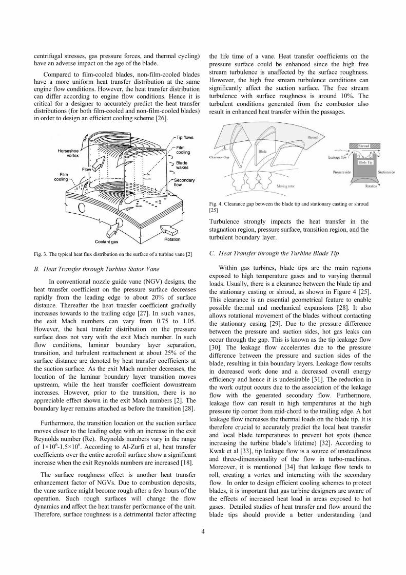
Numerous studies have been performed on heat transfer in gas turbines over the past 15 years. Initial studies focused on quantifying the effects of steady flow gas stands by comparing the transfer of work. The heat transfer was measured based on temperature changes for different turbine inlet temperatures. For example, extreme temperature changes were tested by Cormerais et al [11] by varying the turbine inlet temperatures from 50 ◦C to 500 ◦C with a thermally insulated turbine. [11]. Figure.1 shows a typical heat flux distribution on the surface of a turbine vane [2]. Turbine stator vanes and turbine rotor blades are identified as hot-gas components. Turbine first-stage vanes are exposed to high temperatures of highly turbulent hot gases which are generated in the combustor to produce the power. The hot gas moves into the first stage rotor blades after accelerating through the first stage vanes. Although the inlet velocity of the first stage vanes is 2-3 times higher than the inlet velocity of the first stage blades, the temperature and turbulence are lower at the inlet of the first stage vanes than that of the first stage blades. Furthermore, the first stage blades receive unsteady wake flows from the upstream vane’s trailing edge. Due to the rotation of blades, hot gas may leak from the pressure side to the suction side through the tip gap. This can cause damage to the blade tip near the pressure side trailing edge region. Heat transfer distribution can be identified near the tip region of the blade [2].
Local hot-spot overheating can be prevented using an accurate estimation of heat transfer distribution to design an efficient cooling system [12]. Factors such as the exit Mach number and Reynolds number, boundary layer transitional

3
behaviour, aerofoil surface roughness, free stream turbulence, film coolant injection location, flow separation, and reattachment have a major impact on heat transfer distribution characteristics [2]. Furthermore, the gas to aerofoil heat transfer can vary due to the effects of the above-mentioned factors.
Fig. 1. The typical heat flux distribution on the surface of a turbine vane [2]
A. Heat Transfer through Turbine Rotor Blades
In order to extract energy from the high temperature and pressure gases produced by the combustor, turbine blades are generally exposed to high temperature [12] .Hot gases move into the first stage rotor blades to produce power output [13]. Figure 2 shows the average radial temperature profile at the inlet of the stage 1 turbine rotor blade [14]. Due to rotational movement, there is a variation of peak temperature from the blade pitch line to the tip region. In addition to the radial temperature profile, accurate prediction of the associated unsteady velocity profile and the level turbulence are also important. If the blade temperature prediction is inaccurate only by 10 oC (or 50 oF), the blade life may be reduced by half [13]. This is due to the unsteady high turbulence and highly 3-D complex flow field. Therefore, it is crucial to accurately predict the local heat transfer coefficient as well as the local blade temperature to prevent local hot spots and to increase the life time of turbine blades. Furthermore, to survive within strenuous environments (e.g. high temperature, high stress, and high levels of vibration) blades are often manufactured from exotic materials including super-alloys incorporating numerous methods of blade cooling. Internal air channels, boundary layer cooling, and thermal barrier coatings are the most common cooling methods associated with modern gas turbine blades [15]. Convection and impingement cooling are also used as internal air-cooling methods. In these systems heat is mainly transferred by conduction through the blades and convection to the air flowing inside the blade core. In convection cooling methods, cooling is achieved by passing air through internal passages of the blade core from the hub towards the blade tip [16]. In gas turbines, cooling air comes from the air compressor. The fluid outside is relatively hot and passes through the cooling passages to mix with the main stream at the blade tip. Impingement cooling occurs by hitting the inner surface of the blade with a high velocity air flow. Comparison to conventional convection cooling methods, the impingement cooling method has a high heat transfer rate. Furthermore, film cooling methods are widely used as the external cooling mechanism of gas turbine blades. Pin-fin
technology, cooling effusion, and transpiration cooling are other external cooling methods of gas turbine blades [18], [19].
Fig. 2. Average radial temperature profile at the inlet of the stage 1 turbine rotor blade [14]
In film cooling mechanisms, cooling air is pumped out of the blade via multiple small holes in the structure. A thin layer (a film) of cooling air is created on the external surface of the blade, reducing heat transfer from main flow (which is at a higher temperature than the melting point of the blade material) [16]. The first stationary vane of high temperature gas turbines should be integrated with an efficient cooling system by implementing a film cooling method or an effective convective cooling method. However, this cooling system should cover both vane surface and endwall [17]. Although the air holes are mainly located along the leading edge of the blade, they can be located anywhere along the blade. Gas turbine cooling has a major impact on the efficiency, durability and maintenance of the turbine. Previous work by Al-Zurfi and Turan [18] has assessed the development of a novel cooling technology based on “anti-vortex” concepts to significantly increase the cooling effectiveness. This has been achieved by employing advanced fluid mechanics concepts incorporating boundary layer management methodologies [19]. Large Eddy Simulation (LES) based predictive methods are employed to delineate the underlying aero physics in order to derive rational design methodologies for film cooling [20]. The rotational speed is the dominant factor in determining cooling effectiveness, while the anti-vortex concept reduces the mixing of the main stream and the coolant jets via reverse vortices.
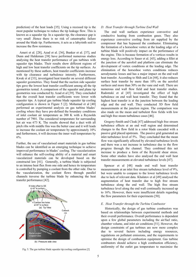
Complex flow phenomenon associated with a gas turbine rotor hot gas passage (including the secondary flows, horseshoe vortex, end wall passage vortex, film cooling, tip flows, waves, and rotation flows) are depicted in Figure 3. Generally, this passage flow is characterised by boundary layer effects [22]. The secondary flows are generated due to the passage pressure gradients and vertical flow structures (such as leading-edge horseshoe vortices, tip-leakage flow vortices and corner vortices) [23]. Horseshoe vortices develop due to the turbine blade-hub junction [24]. They can cause local heat transfer rates and thermal gradients across the blade [25]. Thermal gradients are one of most important parameters in determining the blade life. Thermal gradients (along with
4
centrifugal stresses, gas pressure forces, and thermal cycling) have an adverse impact on the age of the blade.
Compared to film-cooled blades, non-film-cooled blades have a more uniform heat transfer distribution at the same engine flow conditions. However, the heat transfer distribution can differ according to engine flow conditions. Hence it is critical for a designer to accurately predict the heat transfer distributions (for both film-cooled and non-film-cooled blades) in order to design an efficient cooling scheme [26].
Fig. 3. The typical heat flux distribution on the surface of a turbine vane [2]
B. Heat Transfer through Turbine Stator Vane
In conventional nozzle guide vane (NGV) designs, the heat transfer coefficient on the pressure surface decreases rapidly from the leading edge to about 20% of surface distance. Thereafter the heat transfer coefficient gradually increases towards to the trailing edge [27]. In such vanes, the exit Mach numbers can vary from 0.75 to 1.05. However, the heat transfer distribution on the pressure surface does not vary with the exit Mach number. In such flow conditions, laminar boundary layer separation, transition, and turbulent reattachment at about 25% of the surface distance are denoted by heat transfer coefficients at the suction surface. As the exit Mach number decreases, the location of the laminar boundary layer transition moves upstream, while the heat transfer coefficient downstream increases. However, prior to the transition, there is no appreciable effect shown in the exit Mach numbers [2]. The boundary layer remains attached as before the transition [28].
Furthermore, the transition location on the suction surface moves closer to the leading edge with an increase in the exit Reynolds number (Re). Reynolds numbers vary in the range of 1×10⁶-1.5×10⁶. According to Al-Zurfi et al, heat transfer coefficients over the entire aerofoil surface show a significant increase when the exit Reynolds numbers are increased [18].
The surface roughness effect is another heat transfer enhancement factor of NGVs. Due to combustion deposits, the vane surface might become rough after a few hours of the operation. Such rough surfaces will change the flow dynamics and affect the heat transfer performance of the unit. Therefore, surface roughness is a detrimental factor affecting
the life time of a vane. Heat transfer coefficients on the pressure surface could be enhanced since the high free stream turbulence is unaffected by the surface roughness. However, the high free stream turbulence conditions can significantly affect the suction surface. The free stream turbulence with surface roughness is around 10%. The turbulent conditions generated from the combustor also result in enhanced heat transfer within the passages.
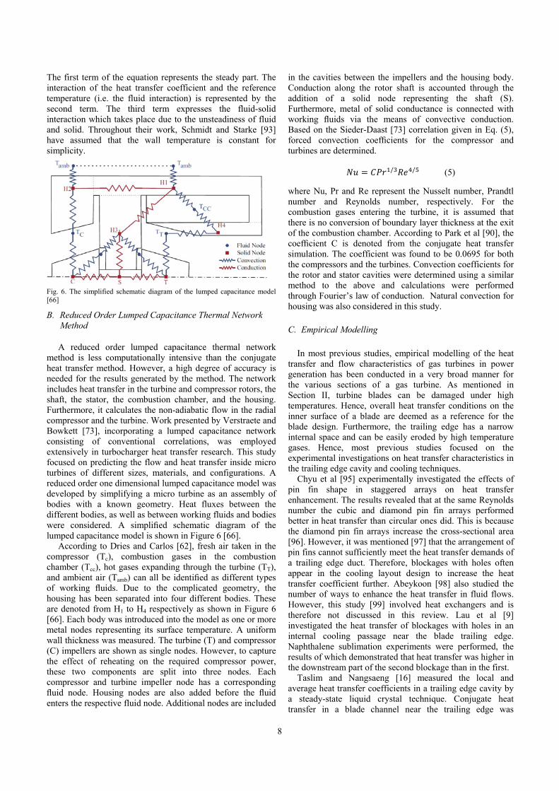
Fig. 4. Clearance gap between the blade tip and stationary casting or shroud [25]
Turbulence strongly impacts the heat transfer in the stagnation region, pressure surface, transition region, and the turbulent boundary layer.
C. Heat Transfer through the Turbine Blade Tip
Within gas turbines, blade tips are the main regions exposed to high temperature gases and to varying thermal loads. Usually, there is a clearance between the blade tip and the stationary casting or shroud, as shown in Figure 4 [25]. This clearance is an essential geometrical feature to enable possible thermal and mechanical expansions [28]. It also allows rotational movement of the blades without contacting the stationary casing [29]. Due to the pressure difference between the pressure and suction sides, hot gas leaks can occur through the gap. This is known as the tip leakage flow [30]. The leakage flow accelerates due to the pressure difference between the pressure and suction sides of the blade, resulting in thin boundary layers. Leakage flow results in decreased work done and a decreased overall energy efficiency and hence it is undesirable [31]. The reduction in the work output occurs due to the association of the leakage flow with the generated secondary flow. Furthermore, leakage flow can result in high temperatures at the high pressure tip corner from mid-chord to the trailing edge. A hot leakage flow increases the thermal loads on the blade tip. It is therefore crucial to accurately predict the local heat transfer and local blade temperatures to prevent hot spots (hence increasing the turbine blade’s lifetime) [32]. According to Kwak et al [33], tip leakage flow is a source of unsteadiness and three-dimensionality of the flow in turbo-machines. Moreover, it is mentioned [34] that leakage flow tends to roll, creating a vortex and interacting with the secondary flow. In order to design efficient cooling schemes to protect blades, it is important that gas turbine designers are aware of the effects of increased heat load in areas exposed to hot gases. Detailed studies of heat transfer and flow around the blade tips should provide a better understanding (and
5
prediction) of the heat loads [35]. Using a recessed tip is the most popular technique to reduce the tip leakage flow. This is known as a squealer tip. In a squealer tip, the clearance gap is very small .Hence there is no risk of catastrophic failure around the blade tip. Furthermore, it acts as a labyrinth seal to increase the flow resistance.
Ameri et al. [28], Azad et al. [36], Bunker et al. [37], and Dunn and Haldeman [38] have performed numerous studies analysing the heat transfer performance of gas turbines with squealer tips blades. Their results show different regions of high and low heat transfer coefficients on the tip surfaces. As mentioned by these authors, heat transfer coefficients increase with tip clearance and turbulence intensity. Furthermore, Kwak et al [33], investigated heat transfer on several different squealer geometries. They found that the suction side squealer tips gave the lowest heat transfer coefficient among all the tip geometries tested. A comparison of the squealer and plane tip geometries was conducted by Azad et al [39]. They concluded that the overall heat transfer coefficients were lower with squealer tips. A typical gas turbine blade squealer tip cooling configuration is shown in Figure 5 [2]. Mohamad et al [40] performed an experimental analysis on gas turbine blades’ cooling where they have pre-defined the boundary conditions of inlet coolant air temperature as 300 K with a Reynolds number of 7901. The considered temperature for surrounding hot air was 673 K. The results showed that a duct with all pitch ribs with middle fins was the better case and it will leads to increase the coolant air temperature by approximately 10% and furthermore, it will decrease the inner wall temperature by 6%.
Further, the use of vascularised smart materials in gas turbine blades can be identified as an emerging technique to achieve improved performance in blades’ cooling. The vascularization will enhance the self-cooling ability of a material and smart vascularized materials can be developed based on the constructal law [41]. Generally, a turbine blade is subjected to an intense heat flux from one side and hence its temperature is controlled by pumping a coolant from the other side. Due to the vascularization, the coolant flows through parallel channels traverse the turbine blade by enhancing the heat transfer performance [42].
Fig. 5. The gas turbine blade squealer tip cooling configuration [2]
D. Heat Transfer through Turbine End Wall
The end wall surfaces experience convective and conductive heating from combustion gases. They also experience convective cooling from air supplied by the compressor that has bypassed the combustor. Eliminating the formation of a horseshoe vortex at the leading edge of a turbine blade will positively impact on the performance of the engine. This is because formation of a vortices results in energy loss. According to Sauer et al. [43], adding a fillet at the junction of the aerofoil and platform can eliminate the development of vortex conditions at the leading edge. The elimination of the horseshoe vortex conditions reduces aerodynamic losses and has a major impact on the end wall heat transfer. According to Shih and Lin [44], it also reduces surface heat transfer by more than 10% on the aerofoil surfaces and more than 30% on the vane end wall. There are numerous end wall flow field and heat transfer studies. Radomski et al [45] investigated the effect of high turbulence on end wall heat transfer. They found that the highest heat transfer is at the junction between the leading edge and the end wall. They conducted 3D flow field measurements at the junction region. The comparison was also made on the mean and turbulent flow fields with low and high free steam turbulence cases [46].
Gregory-Smith and Cleak [47] addressed high free stream turbulence effects at an end wall region and determined changes to the flow field in a rotor blade cascaded with a passive grid placed upstream. The passive grid generated an inlet turbulence level of 5%. They concluded that the mean flow was significantly affected by elevated turbulence levels and there was a net increase in turbulence due to the flow progress through the channel. They combined this net increase to produce a form of the Reynold shear stress. Some other studies have also analysed the end wall heat transfer measurements at elevated turbulence levels [47].
Spencer et al [48] made end wall heat transfer measurements at an inlet free stream turbulence level of 9%, but were unable to compare to the lower turbulence levels due to lack of relevant data. Khalatov et al [49] analysed the augmentation of heat transfer due to high free stream turbulence along the end wall. The high free stream turbulence level along the end wall continually increased up to 16%. However, there were insufficient details regarding the flow parameters for their experiments [50].
E. Heat Transfer through the Turbine Combustor
Historically, the design of gas turbine combustors was based on relationships between experimental methods and their overall performance. Overall performance is dependent upon a few global parameters including the air/fuel ratio, chamber volume, and inlet air conditions [51]. However, the design constraints of gas turbines are now more complex due to several factors including energy resources, regulations on pollutant emissions, and the requirements to optimise the design of combustion equipment. Gas turbine combustors should achieve a high combustion efficiency, uniformity of the outlet gas temperature to maximize the

6
lifetime of turbine blades, low pressure loss, and smooth ignition conditions [51]. Achieving the aforementioned performance criteria is quite difficult with traditional methods. This is because with traditional methods there is little or no consideration given to variations in changing parameters such as temperature and velocity. Modern methods of improving gas turbine combustor efficiency are based on analysis of heat transfer and flow characteristics with advanced computational tools [52]. Combustion in a gas turbine occurs inside a combustor which operates under high temperatures and a high level of thermal stress. During the engine operation, a high pressure flow of air is generated by the compressor and then fuel is sprayed into the air flow which will be converted to a high pressure/temperature flow with combustion. Heat transfer during combustion mainly takes place by radiation and convection of combustion gases within the combustor. The distance between the flame and the walls and absorption of the cold combustion gases affects the radiative heat exchange [53]. In modern gas turbines, heat transfer is very low due to a high bulk flow velocity and short residence times [54]. Waitz et al [55] proposed to use refractory ceramics in gas turbine engines to achieve both lean conditions during combustion and also an effective cooling on combustor walls, simultaneously. However, any combustor used in gas turbines are expected to meet the following main requirements: a high combustion efficiency, uniformity of outlet gases, a suitable temperature level to maximise the life of turbine blades and nozzle guide vanes, wider stability limits, low pressure losses and a smooth ignition [56].
A combustor liner is heated by convection and radiation from the exhaust gas inside the unit [57]. It is cooled by radiation to the outer casing and convection to the casing air passage. However, in gas turbine combustion chambers, a large proportion of the total heat flux to the liner walls is by radiation from the flame. The radiant heating has a significant impact on the liner durability. In order to maximise liner life, it is essential to maintain the prevailing temperature and temperature gradients below a certain level. In order to remove heat from the liner, there is a film of cold air on the inner surface of a liner [58]. Cooling of the walls by convection and the increase in pressure increases the amount of radiative heat transferred to the inner walls. Cooling will be less effective due to the high temperature of the inlet combustion air [59].
Turan et al [57] were the first to attempt to apply the Computational Fluid Dynamics (CFD) tools to predict the three-dimensional reacting flow aero thermochemical profiles in a typical industrial combustor configuration. Work by Jones and Priddin [60], Jones and McGuirk [61], Coupland and Priddin [62] and Jones et al [63] investigated the gas turbine combustor heat transfer. However, these studies did not analyse the radiative heat transfer.
Boysan et al [64] used a flux model to account for the effects of radiation in a gas turbine combustor. They solved three 2nd order linear differential equations for the fluxes in the radial, axial, and tangential directions. In their flux model, the radiation contribution was considered in the enthalpy equation via a source term calculated from the fluxes. However, the authors did not specify the boundary conditions used for the
calculation of the radiation heat transfer. Sampath et al [65] used the same flux model which is discussed above to compute radiation heat transfer in a gas turbine. Because their aim was different, the predictions related to heat fluxes were not presented in their paper.
Lockwood et al [66] used discrete ordinate transfer models to predict radiation. They assumed an adiabatic flame. However, they did not employ an enthalpy equation and the temperature distribution was determined as a function of the instantaneous mixture fraction using an equilibrium method developed by Gordon et al [67]. As the equilibrium model did not consider the effects of radiative heat transfer on the flow, temperature field, and chemical reaction, the research failed to satisfy the desired objectives.
III. MODELING
A. First Principal Modelling
Conjugate heat transfer model: When considering the current state-of-the art, heat transfer simulation models can be divided into two types: the conjugate heat transfer (CHT) method and the loosely coupled method. The conjugate heat transfer method solves the governing equations relating to fluid flow and the heat conduction equations associated with the solid part. It uses the same discretization simultaneously [68]. In the loosely coupled method, different solvers are used for the fluid and solid regions. The heat flux at the blade and the fluid-solid interface is established through an iterative exchange of the solution variables [69]. Currently, both methods are used to simulate heat transfer within turbine components [70].
Most existing studies [71] compare a CHT simulation for a turbine cascaded to an uncoupled approach. These studies concluded that [72], for complex geometries and regions of low velocity or flow separation, there is negligible coupling between the flow field and thermal field of a solid leading to incorrect results [73]. A comparison between a coupled and an uncoupled heat transfer simulation of a turbine blade (cooled via convection) was presented by Heselhaus [74]. It reported a significant difference in the material temperatures with a wall temperature gradient. In the study, Heselhaus [74] developed a coupling scheme using convective boundary conditions with virtual values for the heat transfer coefficient on the solid side and the wall temperature at the fluid side. Montenay [75] used this method to investigate heat transfer in an engine internal cavity. The importance of accurate flow modelling was highlighted in another study where the turbine nozzle gas vanes were simulated in a CHT analysis [75]. Work by Sun et al [76] assumed a “Frozen Flow” as a coupling option and the energy equation was solved while the flow remained frozen in CFD simulations. CFD simulation was employed during the thermal coupling process for specified time intervals. An in-house code was used for the finite element analysis and two different CFD solvers were implemented for the coupling. Both a commercial code and an in-house code were used. Their research investigated two case studies: an industrial low pressure turbine and a high pressure compressor. The simulation results showed good agreement of wall temperatures with the industrial test rig data. Based on their results, it can be concluded that coupled solutions can be obtained in sufficiently short turnaround

7
times for use in design. On the other hand, to achieve a reduction in computational times by 3-5% (compared to other studies) a modified coupling scheme was developed by Wang [68] (based on the previous work by Heselhaus [74]).
As mentioned in Section II, one of the most important factors in determining the life of a blade is its temperature distribution. To calculate the blade temperatures accurately, conditions of external hot gases, metal conduction, and internal coolant should be calculated simultaneously (using the conjugate heat transfer method) [77]. Bohn et al [78], Luo et al [79], Ledezma et al [80] and Wang et al [81] performed the heat transfer modelling on C3X and Mark-II Vane profiles in a single solver. The C3X vane profile has an arrangement of 10 cooling holes and a circular trailing edge. The Mark-II vane profile consists of a high pressure turbine nozzle guide vane which is convectively cooled by 10 cooling channels supplied with atmospheric air. Both used ASTM 310 stainless steel [29]. In Bohn’s studies [78], an investigation was performed regarding the applications of CHT methods relating the aerodynamics and aerothermodynamics of transonic turbine guide vanes cooled by convection. Their codes used heat transfer data at the initial stage. The generated numerical results for uncoated vanes agreed with the experimental data up to 80%. Therefore, the numerical investigations were extended to include coated vanes. To get a smooth temperature distribution across the blade, a parametric study of the cooling fluid mass flow was performed for the coated configuration. Bohn investigated configurations consisting of atmospheric plasma layers. Other studies [82] used three dimensional solvers and CHT methods to calculate the temperature distribution of vanes and blades which have more complex internal cooling passages. However, 3D modelling of vanes and blades with complex cooling passages is a time-consuming task [82]. According to Kusterer’s studies [82], there is good agreement between the conjugate results and experimental measurements of temperature distribution across the blade geometry (even though the experimental results did not agree with the numerical results). CHT and coupled flow calculation techniques were applied to 3D cooling configurations[83]. It was concluded that since conjugate calculation codes are associated with 3D cooling configurations, they can be employed as a useful tool to support the thermal design process regarding gas turbine blade cooling. In order to provide thermal load data for comparison with the results of conjugate blade analysis, thermal index paint measurements were performed. In Mangani’s studies [84], conjugate numerical methodology was employed to predict the metal temperature of a 3D first stage gas turbine blade, under normal operating conditions. Numerical and experimental results were justified in terms of pressure and temperature distribution on the blade wall at mid span and heat transfer coefficient profiles.
In addition to the aforementioned studies, Wan et al [86] and Takahashi et al [87] have also performed some research work on the conjugate heat transfer method. They used 1D simulation approaches to investigate internal cooling passages. An advantage of 1D modelling is that it is less time consuming compared to 3D modelling [88]. One may use 1D modelling if they are not too strict on the accuracy of the results but expecting to have some general understanding on the heat transfer behaviour [89].
Unsteady convective heat transfer model: Most research conducted under unsteady flow conditions focused on the
combustor exit flow field and its influence on the aerothermal turbine performance [90]. Kerrebrock and Mikolajczak [91] described the positive/negative jet effects generated by the non-uniform turbine inlet pressures, temperature fields and the relative motion of the stator and rotor blades. Ong and Miller [92] and Sipatov et al [83] observed the mechanism of redistribution of hot and cold gas regions in the rotor passage. This redistribution occurs due to the periodically altered incidence angle for a rotor blade. Due to circumferential temperature variation, the incidence angle changes periodically which results in gas redistribution. A limitation of this study is that it assumed an isothermal wall. This is quite problematic because in the region of the secondary flow boundaries, there is an increase in wall temperature. Furthermore, there are some regions with reduced temperatures.
Unsteady convective heat transfer model with time average and time dependent parameters: The development of an unsteady heat transfer convective model was done by Schmidt and Starke [93] and they developed it by covering the time averaged and time-dependent heat transfer approaches and hence the solutions were derived by using an integral method. According to Newton’s law of cooling, the heat flux q in a convective heat transfer under study conditions can be given by Eq. (1).
q = h (Tref − T∞) (1) where, h is the convective heat transfer coefficient Tref and T∞ are the reference temperatures (e.g.: wall surface temperature) and the free stream temperature, respectively. According to Schmidt and Starke [93], the parameters included in the right side of the equation can be regarded as time dependent parameters and therefore to describe this time dependent behaviour, Eq. (1) should be decomposed to include a mean part and a harmonic oscillation part as shown in Eq. (2).
∑ ́ cos ∑ cos
∅ , ∑ , cos ∅ , (2)
Since both temperature oscillations are allowed to be phase shifted relative to the heat transfer coefficient, ɸ ref,i and ɸ w,i can be denoted as phase shifts.
By focusing on one frequency for convective oscillations, Eq. (2) can be simplified as illustrated in Eq. (3).
cos cos ∅
cos ∅ 3
Hence, as the focus is on the time average data, the integration of Equation 3 over one period leads to the overall heat flux and can be considered as a periodic unsteady convection.
2
0
′ ′1
2′ cos ∅
1
2′ ′ cos ∅ 4
8
The first term of the equation represents the steady part. The interaction of the heat transfer coefficient and the reference temperature (i.e. the fluid interaction) is represented by the second term. The third term expresses the fluid-solid interaction which takes place due to the unsteadiness of fluid and solid. Throughout their work, Schmidt and Starke [93] have assumed that the wall temperature is constant for simplicity.
Fig. 6. The simplified schematic diagram of the lumped capacitance model [66]
B. Reduced Order Lumped Capacitance Thermal Network Method
A reduced order lumped capacitance thermal network method is less computationally intensive than the conjugate heat transfer method. However, a high degree of accuracy is needed for the results generated by the method. The network includes heat transfer in the turbine and compressor rotors, the shaft, the stator, the combustion chamber, and the housing. Furthermore, it calculates the non-adiabatic flow in the radial compressor and the turbine. Work presented by Verstraete and Bowkett [73], incorporating a lumped capacitance network consisting of conventional correlations, was employed extensively in turbocharger heat transfer research. This study focused on predicting the flow and heat transfer inside micro turbines of different sizes, materials, and configurations. A reduced order one dimensional lumped capacitance model was developed by simplifying a micro turbine as an assembly of bodies with a known geometry. Heat fluxes between the different bodies, as well as between working fluids and bodies were considered. A simplified schematic diagram of the lumped capacitance model is shown in Figure 6 [66]. According to Dries and Carlos [62], fresh air taken in the compressor (Tc), combustion gases in the combustion chamber (Tcc), hot gases expanding through the turbine (TT), and ambient air (Tamb) can all be identified as different types of working fluids. Due to the complicated geometry, the housing has been separated into four different bodies. These are denoted from H1 to H4 respectively as shown in Figure 6 [66]. Each body was introduced into the model as one or more metal nodes representing its surface temperature. A uniform wall thickness was measured. The turbine (T) and compressor (C) impellers are shown as single nodes. However, to capture the effect of reheating on the required compressor power, these two components are split into three nodes. Each compressor and turbine impeller node has a corresponding fluid node. Housing nodes are also added before the fluid enters the respective fluid node. Additional nodes are included
in the cavities between the impellers and the housing body. Conduction along the rotor shaft is accounted through the addition of a solid node representing the shaft (S). Furthermore, metal of solid conductance is connected with working fluids via the means of convective conduction. Based on the Sieder-Daast [73] correlation given in Eq. (5), forced convection coefficients for the compressor and turbines are determined.
/ / (5)
where Nu, Pr and Re represent the Nusselt number, Prandtl number and Reynolds number, respectively. For the combustion gases entering the turbine, it is assumed that there is no conversion of boundary layer thickness at the exit of the combustion chamber. According to Park et al [90], the coefficient C is denoted from the conjugate heat transfer simulation. The coefficient was found to be 0.0695 for both the compressors and the turbines. Convection coefficients for the rotor and stator cavities were determined using a similar method to the above and calculations were performed through Fourier’s law of conduction. Natural convection for housing was also considered in this study.
C. Empirical Modelling
In most previous studies, empirical modelling of the heat transfer and flow characteristics of gas turbines in power generation has been conducted in a very broad manner for the various sections of a gas turbine. As mentioned in Section II, turbine blades can be damaged under high temperatures. Hence, overall heat transfer conditions on the inner surface of a blade are deemed as a reference for the blade design. Furthermore, the trailing edge has a narrow internal space and can be easily eroded by high temperature gases. Hence, most previous studies focused on the experimental investigations on heat transfer characteristics in the trailing edge cavity and cooling techniques. Chyu et al [95] experimentally investigated the effects of pin fin shape in staggered arrays on heat transfer enhancement. The results revealed that at the same Reynolds number the cubic and diamond pin fin arrays performed better in heat transfer than circular ones did. This is because the diamond pin fin arrays increase the cross-sectional area [96]. However, it was mentioned [97] that the arrangement of pin fins cannot sufficiently meet the heat transfer demands of a trailing edge duct. Therefore, blockages with holes often appear in the cooling layout design to increase the heat transfer coefficient further. Abeykoon [98] also studied the number of ways to enhance the heat transfer in fluid flows. However, this study [99] involved heat exchangers and is therefore not discussed in this review. Lau et al [9] investigated the heat transfer of blockages with holes in an internal cooling passage near the blade trailing edge. Naphthalene sublimation experiments were performed, the results of which demonstrated that heat transfer was higher in the downstream part of the second blockage than in the first. Taslim and Nangsaeng [16] measured the local and average heat transfer coefficients in a trailing edge cavity by a steady-state liquid crystal technique. Conjugate heat transfer in a blade channel near the trailing edge was
9
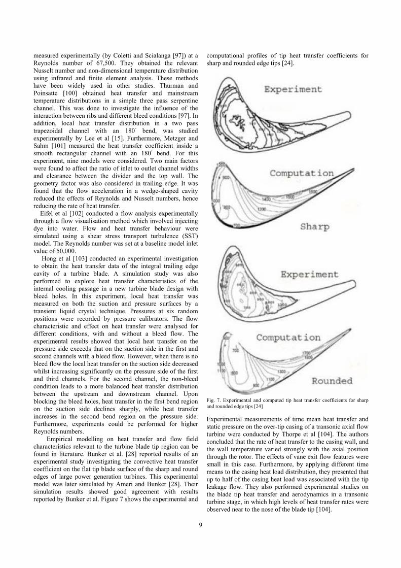
measured experimentally (by Coletti and Scialanga [97]) at a Reynolds number of 67,500. They obtained the relevant Nusselt number and non-dimensional temperature distribution using infrared and finite element analysis. These methods have been widely used in other studies. Thurman and Poinsatte [100] obtained heat transfer and mainstream temperature distributions in a simple three pass serpentine channel. This was done to investigate the influence of the interaction between ribs and different bleed conditions [97]. In addition, local heat transfer distribution in a two pass trapezoidal channel with an 180◦ bend, was studied experimentally by Lee et al [15]. Furthermore, Metzger and Sahm [101] measured the heat transfer coefficient inside a smooth rectangular channel with an 180◦ bend. For this experiment, nine models were considered. Two main factors were found to affect the ratio of inlet to outlet channel widths and clearance between the divider and the top wall. The geometry factor was also considered in trailing edge. It was found that the flow acceleration in a wedge-shaped cavity reduced the effects of Reynolds and Nusselt numbers, hence reducing the rate of heat transfer. Eifel et al [102] conducted a flow analysis experimentally through a flow visualisation method which involved injecting dye into water. Flow and heat transfer behaviour were simulated using a shear stress transport turbulence (SST) model. The Reynolds number was set at a baseline model inlet value of 50,000. Hong et al [103] conducted an experimental investigation to obtain the heat transfer data of the integral trailing edge cavity of a turbine blade. A simulation study was also performed to explore heat transfer characteristics of the internal cooling passage in a new turbine blade design with bleed holes. In this experiment, local heat transfer was measured on both the suction and pressure surfaces by a transient liquid crystal technique. Pressures at six random positions were recorded by pressure calibrators. The flow characteristic and effect on heat transfer were analysed for different conditions, with and without a bleed flow. The experimental results showed that local heat transfer on the pressure side exceeds that on the suction side in the first and second channels with a bleed flow. However, when there is no bleed flow the local heat transfer on the suction side decreased whilst increasing significantly on the pressure side of the first and third channels. For the second channel, the non-bleed condition leads to a more balanced heat transfer distribution between the upstream and downstream channel. Upon blocking the bleed holes, heat transfer in the first bend region on the suction side declines sharply, while heat transfer increases in the second bend region on the pressure side. Furthermore, experiments could be performed for higher Reynolds numbers. Empirical modelling on heat transfer and flow field characteristics relevant to the turbine blade tip region can be found in literature. Bunker et al. [28] reported results of an experimental study investigating the convective heat transfer coefficient on the flat tip blade surface of the sharp and round edges of large power generation turbines. This experimental model was later simulated by Ameri and Bunker [28]. Their simulation results showed good agreement with results reported by Bunker et al. Figure 7 shows the experimental and
computational profiles of tip heat transfer coefficients for sharp and rounded edge tips [24].
Fig. 7. Experimental and computed tip heat transfer coefficients for sharp and rounded edge tips [24]
Experimental measurements of time mean heat transfer and static pressure on the over-tip casing of a transonic axial flow turbine were conducted by Thorpe et al [104]. The authors concluded that the rate of heat transfer to the casing wall, and the wall temperature varied strongly with the axial position through the rotor. The effects of vane exit flow features were small in this case. Furthermore, by applying different time means to the casing heat load distribution, they presented that up to half of the casing heat load was associated with the tip leakage flow. They also performed experimental studies on the blade tip heat transfer and aerodynamics in a transonic turbine stage, in which high levels of heat transfer rates were observed near to the nose of the blade tip [104].

10
Chana and Jones [105] performed detailed experimental measurements of heat transfer on the shroud-less rotor blade tip and casing with and without non-uniform inlet temperatures. Camci [106] investigated the aerodynamic characteristics of partial and full-length squealer rims (shown in Figure 8 [97]) in an axial turbine. As shown in Figure 8 [97], this was conducted in suction side type aerofoil shapes and channel type aerofoil shapes. Rhee and Cho [105] also measured the local heat transfer characteristics around turbine blade tips, the shroud, and the near-tip surface of a rotary blade in a low speed annular cascade. They examined the effects of rotation and the incoming flow incidence angle on heat transfer performance.
Fig. 8. The studied squealer rims [97]
Radomski et al [45] found that high free stream turbulence along a gas turbine aerofoil and strong secondary flows along the end wall significantly increased convective heat transfer. In this experiment, flow field and heat transfer data were measured and compared with low free stream turbulence levels of 0.6%. Furthermore, a simulation was performed for a combustor with a turbulence level of 19.5%, using an active grid. These experiments were conducted using a scaled-up first stage stator vane geometry. Surface temperatures on a constant heat flux plate, placed on the end wall surface, were measured using infrared thermography. A Laser Doppler Velocimeter (LDV) was also used to measure all three components (film cooling holes, tip cap cooling holes, and the squealer tip) and the mean and fluctuating velocities of the leading edge horseshoe vortex. The results indicated that the mean flow fields for the leading edge horseshoe vortex were similar for low and high free stream turbulence cases. According to this experiment, it can be concluded that the high free stream turbulence increased the end wall heat transfer. However, due to the low number of measurements made for the most intense vortex motions, this study did not succeed in matching the regions of most intense vortex and end wall heat transfer.
D. Finite Element Modelling
When analysing the heat transfer and flow characteristics of a complex component/device partial differential equations and empirical modelling play an important role. Powerful algorithms and data structures are required to solve them and validate the physics-based and/or empirical modelling in an effective manner. Finite Element Modelling (FEM) deals with a large number of unknowns and reduces the initial problem complexity. Therefore, many studies have been performed using finite element modelling to evaluate heat transfer and flow characteristics.
Ameri and Bunker [28] investigated the convective heat transfer coefficient across the first stage blade tip surface of large scale power generation turbines. Simulations were performed using a multi-block computer code. The code was known as LeRC-HT and is used as a solver of flow simulations relating to complex geometries. As mentioned by the authors, this code was designed following the previous work reported by Arnone [107]. In another study by Ameri et al [32], the same code was used to solve a fully compressible Reynolds-averaged, Navier-Strokes equation through a multi-stage Runga-Kutta based multi-grid method. To discretize the equations, the algorithm uses the finite volume method. The discretization of convective terms was carried out using central differencing together with an artificial dissipation. According to Rigby’s research [108], the present version of code employs the k-ω turbulence model. This model can be integrated with walls and no wall functions. Values for the Prandtl number (0.9 and 0.72) were used to determine the turbulent and other conditions respectively. Viscosity is a function of temperature and based on the power law was given a value of 0.7, while Cp was assumed constant. Two different modelling approaches were considered based on geometry and grids. Grids were generated using a computer program called GridPro and models related to the heat transfer analysis of sharp edge and radiused edge cases. A model with a side wall was used to study the sharp edge case under slip and non-slip boundary conditions. Moreover, slip boundary conditions with side walls were used for the radiused edge case to conserve the computation time [109].
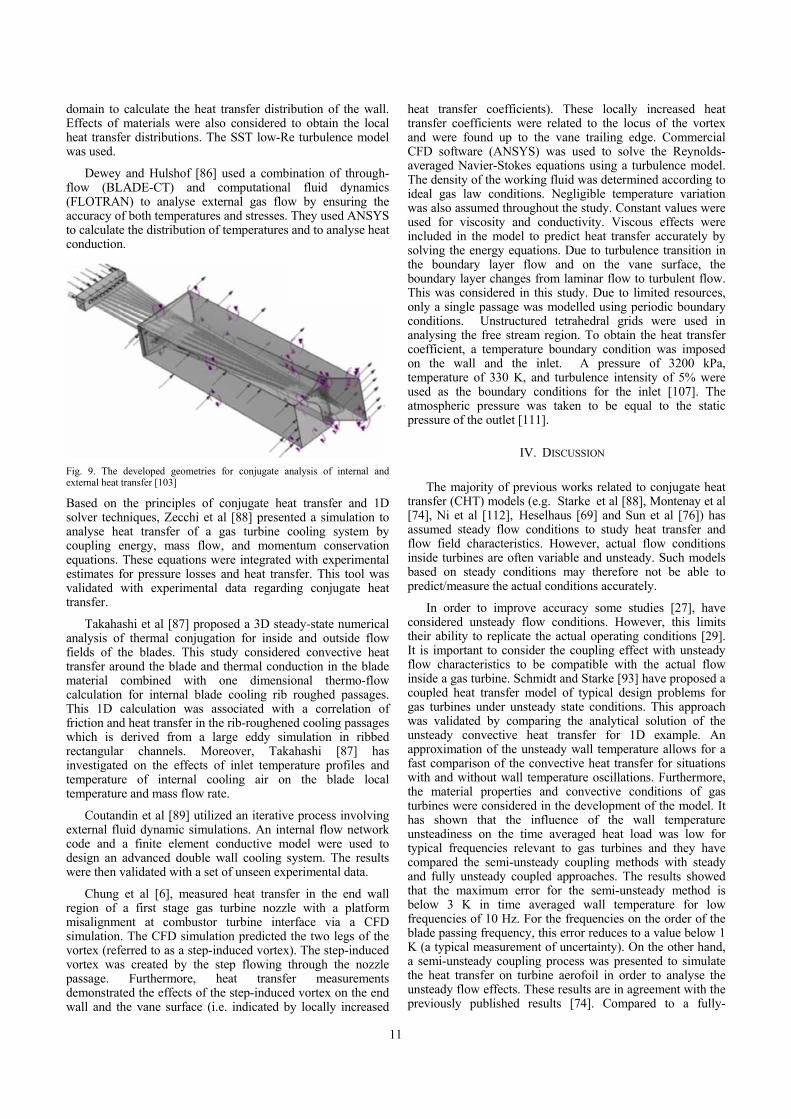
Kim et al [110] conducted an analysis to obtain the conjugate heat transfer data in a gas turbine blade. The study involved analysis of thermal and mechanical characteristics, using a commercial code (CFX-11) under standard operating conditions. Furthermore, thermal stress was calculated using a commercial code developed by ANSYS. The study focused on the hot component of a blade in the second row. The blade consists of 10 conventional ribbed and smooth cooling passages (a complete row has 92 rotating blades). In order to form a continuous ring at full operating speed, these blades rely on an integral shroud. Some key characteristics of the hot gas side of a turbine are: firing temperature of 1327◦C, exhaust temperature of 601◦C, exhaust flow rate of 438.8kg/s, inlet total pressure of 1.531 MPa, and the exit static pressure of 0.104 MPa. Zuckerman and Lior [111] have chosen Computational Fluid Dynamics (CFD) code for modelling to solve Navier-Strokes equations using an explicit finite volume method. The grids of computational domain (mainly consisting of flow domain and structure domain) were created using GAMBIT solid modelling. Geometries developed for conjugate analysis of internal and external heat transfer are shown in Figure 9. Grids were created regarding the external flow domain, internal passage domain, and blade material
11
domain to calculate the heat transfer distribution of the wall. Effects of materials were also considered to obtain the local heat transfer distributions. The SST low-Re turbulence model was used.
Dewey and Hulshof [86] used a combination of through-flow (BLADE-CT) and computational fluid dynamics (FLOTRAN) to analyse external gas flow by ensuring the accuracy of both temperatures and stresses. They used ANSYS to calculate the distribution of temperatures and to analyse heat conduction.
Fig. 9. The developed geometries for conjugate analysis of internal and external heat transfer [103]
Based on the principles of conjugate heat transfer and 1D solver techniques, Zecchi et al [88] presented a simulation to analyse heat transfer of a gas turbine cooling system by coupling energy, mass flow, and momentum conservation equations. These equations were integrated with experimental estimates for pressure losses and heat transfer. This tool was validated with experimental data regarding conjugate heat transfer.
Takahashi et al [87] proposed a 3D steady-state numerical analysis of thermal conjugation for inside and outside flow fields of the blades. This study considered convective heat transfer around the blade and thermal conduction in the blade material combined with one dimensional thermo-flow calculation for internal blade cooling rib roughed passages. This 1D calculation was associated with a correlation of friction and heat transfer in the rib-roughened cooling passages which is derived from a large eddy simulation in ribbed rectangular channels. Moreover, Takahashi [87] has investigated on the effects of inlet temperature profiles and temperature of internal cooling air on the blade local temperature and mass flow rate.
Coutandin et al [89] utilized an iterative process involving external fluid dynamic simulations. An internal flow network code and a finite element conductive model were used to design an advanced double wall cooling system. The results were then validated with a set of unseen experimental data.
Chung et al [6], measured heat transfer in the end wall region of a first stage gas turbine nozzle with a platform misalignment at combustor turbine interface via a CFD simulation. The CFD simulation predicted the two legs of the vortex (referred to as a step-induced vortex). The step-induced vortex was created by the step flowing through the nozzle passage. Furthermore, heat transfer measurements demonstrated the effects of the step-induced vortex on the end wall and the vane surface (i.e. indicated by locally increased
heat transfer coefficients). These locally increased heat transfer coefficients were related to the locus of the vortex and were found up to the vane trailing edge. Commercial CFD software (ANSYS) was used to solve the Reynolds-averaged Navier-Stokes equations using a turbulence model. The density of the working fluid was determined according to ideal gas law conditions. Negligible temperature variation was also assumed throughout the study. Constant values were used for viscosity and conductivity. Viscous effects were included in the model to predict heat transfer accurately by solving the energy equations. Due to turbulence transition in the boundary layer flow and on the vane surface, the boundary layer changes from laminar flow to turbulent flow. This was considered in this study. Due to limited resources, only a single passage was modelled using periodic boundary conditions. Unstructured tetrahedral grids were used in analysing the free stream region. To obtain the heat transfer coefficient, a temperature boundary condition was imposed on the wall and the inlet. A pressure of 3200 kPa, temperature of 330 K, and turbulence intensity of 5% were used as the boundary conditions for the inlet [107]. The atmospheric pressure was taken to be equal to the static pressure of the outlet [111].
IV. DISCUSSION
The majority of previous works related to conjugate heat
transfer (CHT) models (e.g. Starke et al [88], Montenay et al [74], Ni et al [112], Heselhaus [69] and Sun et al [76]) has assumed steady flow conditions to study heat transfer and flow field characteristics. However, actual flow conditions inside turbines are often variable and unsteady. Such models based on steady conditions may therefore not be able to predict/measure the actual conditions accurately.
In order to improve accuracy some studies [27], have considered unsteady flow conditions. However, this limits their ability to replicate the actual operating conditions [29]. It is important to consider the coupling effect with unsteady flow characteristics to be compatible with the actual flow inside a gas turbine. Schmidt and Starke [93] have proposed a coupled heat transfer model of typical design problems for gas turbines under unsteady state conditions. This approach was validated by comparing the analytical solution of the unsteady convective heat transfer for 1D example. An approximation of the unsteady wall temperature allows for a fast comparison of the convective heat transfer for situations with and without wall temperature oscillations. Furthermore, the material properties and convective conditions of gas turbines were considered in the development of the model. It has shown that the influence of the wall temperature unsteadiness on the time averaged heat load was low for typical frequencies relevant to gas turbines and they have compared the semi-unsteady coupling methods with steady and fully unsteady coupled approaches. The results showed that the maximum error for the semi-unsteady method is below 3 K in time averaged wall temperature for low frequencies of 10 Hz. For the frequencies on the order of the blade passing frequency, this error reduces to a value below 1 K (a typical measurement of uncertainty). On the other hand, a semi-unsteady coupling process was presented to simulate the heat transfer on turbine aerofoil in order to analyse the unsteady flow effects. These results are in agreement with the previously published results [74]. Compared to a fully-

12
unsteady heat transfer simulation, the semi-unsteady method reduces the computational time by a factor between 20 and 30.
A 1D lumped capacitance model was developed and applied to micro gas turbines of different sizes, materials and configurations [113].
Fig. 10. Heat transfer for the baseline configuration [106]
According to Figure 10, the heat load conducted through the shaft represents only 4% of the total power output and this confirms that at high rotational speeds the effects of heat transfer on the compressor performance are relatively small. Furthermore, because of the high heat loss in the combustion chamber and the high conductivity of stainless steel compared to Inconel shafts, compressor heating through the housing is of greater magnitude. This implies that the effect of housing cannot be ignored when trying to reduce the impact of heat transfer on the compressor rotor. The heat rate of the compressor rotor also confirms that most of the heat generation of the air occurs at the compressor inlet (where the air temperature is low) and downstream thermal energy transfer occurs from the compressor to the housing. According to the results of the lumped capacitance model relating to material conductivity, materials with a greater thermal conductivity cool the turbine rotor, as they allow more heat to be transferred to the compressor and housing. Even if the higher conductive material cannot withstand high temperatures, cooling can increase the turbine inlet temperatures. Because of the increase in internal heat transfer, the performance of the compressor is reduced. It is mentioned that the impact of heat transfer increases while the flow value decreases more rapidly than the component of surface area due to the decrease in the size of the micro turbines. However, as reported in the literature, limiting the effect of inter-component heat transfer is crucial to achieve an acceptable thermal efficiency, especially when higher turbine inlet temperatures are adopted [113].
An empirical approach proposed by Hong et al [102] investigated heat transfer on the inner surfaces of a novel turbine blade design. This study also investigated the pressure drop on the leading edge cavity. The study was performed with and without bleed flow for five different mass flow rates. It concluded that the local heat transfer on the pressure side is better than that on the suction side in the first and second passages with a bleed flow. Furthermore, a reduction in local heat transfer on the suction side of the first and third passages was noticed after the bleed holes were blocked. However, the maximum magnitude of local heat transfer did not change in the second passage due to the blockage of bleed holes. An ‘M’ shaped distribution was created of the average Nusselt
numbers for six positions along the flow path in the trailing edge cavity (under all conditions of Reynolds number). There were limitations in this study due to instantaneous measurements in temperature, time and physical property parameters of the testing surfaces. Also, this research only focused on heat transfer in the trailing edge cavity of a gas turbine.
Fig. 11. The external heat transfer coefficient distribution on the blade surface [102]
Fig. 12. 0.5 along different sections on the external blade surface[102]
Ameri and Bunker [28] proposed an algebraic turbulence
model to study heat transfer inside gas turbines. Upstream of the blade tip was recessed by the casing. Furthermore, they tested their turbulence model results against the experimental heat transfer data published by Metzger et al [101] and good agreement was achieved. In order to calculate the blade tip heat transfer of the model it was assumed that the flow is periodic in their computational model. However, based on the results that they got, it was mentioned that the assumption of a periodic flow was invalid and therefore the entire passage needs to be modelled.
Kim et al. [110] performed finite element modelling on conjugate heat transfer in a gas turbine blade and found that the maximum heat transfer rate occurs on the stagnation point of the leading edge due to impingement of the main flow. The lowest heat transfer coefficients appear at the trailing edge adjacent to both the pressure and suction sides due to the development of the thermal boundary layer. The highest heat transfer coefficients are found on tip section among various cross sections. Heat transfer coefficient

13
values are higher on the pressure side than on the suction side. Figure 11 shows the external heat transfer coefficient distribution along the blade surface while Nu/Rec
0.5 along different sections on the external blade surface is shown in Figure 12. The internal heat transfer distribution in all the passages inside the turbine is shown in Figure 13 which is based on the Dittus and Boelter equation given in Eq. (6). [110].
Fig. 13. The internal heat transfer distributions in all passages [102]
Fig. 14. The heat transfer distribution on the end wall surface [6]
The authors calculated the Nu ratio (Nu/Nuo) - Averaged Nusselt number normalized by Reynolds number), cross sectional diameter, flow temperature and the Nusselt number in a smooth circular pipe (Nuo).
0.023 0.8 0.4 (6)
According to their results, the heat transfer coefficients ranged from 500 to 4500 W/m2 as shown in Figure 13. Moreover, work by Chung et al [6] reported the heat transfer coefficient distributions on the end wall and on the vane surface as shown in Figures 14 and 15, respectively. For the end wall section, it was found that the step inlet case has the
highest heat transfer at the entrance region. However, the upstream step produces a new boundary layer near the vane leading edge and this was found to be an exception which occurred due to flow reattachment[111]. This thinning boundary layer enhances the overall heat transfer while weakening the horseshoe vortex formation. Hence, less heat transfer occurs near the pressure side.
Fig. 15. The internal heat transfer coefficient distributions on the vane surface [6]
A steep heat transfer gradient was formed in the region surrounding the nozzle throat due to the laminar to turbulent transition in the boundary layer. On the vane surface the leading edge heat transfer coefficient (related to the pressure side) is highest as the incoming flow impinges on the leading edge [112]. After impingement, the heat transfer decreases rapidly with boundary layer development and increases with flow acceleration [113]. However this model only focused on a specific section of the turbine and the case of misalignment of the end wall platform at the combustor-turbine interface [114]. Continued investigation of fluid flow and heat transfer in each section of gas turbines is required [6].
A. Current Challenges to the gas turbine based power generation industry
It has been predicted that the overall electrical energy usage will double globally by 2030, while it will triple in developing countries [115]. Hence, it is essential to search for new energy sources while improving the efficiency of the existing power generation techniques [116]. Some major challenges to the current power generation sector are discussed below.
Limitations of the materials in terms of the temperature: Thermal efficiency of power generation cycles can be improved by increasing the range of operating temperatures
14
(i.e. the lowest and highest temperatures of the thermodynamic cycle). However, it is practically difficult to decrease the lowest temperature to lower than the atmospheric temperature. Further, the maximum temperature depends on the nature of materials within the turbine. Therefore, it is necessary to develop advanced materials which can withstand high temperatures. There is ongoing research in this area [115]. However, turbines using these advanced materials will be expensive and hence end users might have to pay (or not) extra for using energy depending on the overall increase to the efficiency figures due to the new materials. Hence, the energy supplier may not find this as an economical option yet as they will not be able cover their expected profit margins.
Blade cooling: The use of increased firing temperatures has led to the use of advanced blade cooling techniques dealing with high temperatures. Manufacturers have encountered problems with cooling techniques, ranging from failure of thermal barriers and their attachment systems, to insufficient blade cooling leading to thermal distress. Therefore, redesign and modifications have addressed such problems in many machines [116].Blade cooling is therefore another area that needs further improvements.
Corrosion: Corrosion is one of the major issues in any type of power plant. Due to their potential to react with metal components, fuel and ambient air are mainly involved in corrosion. Many types of chemical reactions are possible and can lead to many different types of corrosion. The effects of corrosion can resemble both fouling and erosion. Some types of corrosion cause a build-up of corrosion products, while others cause metal to be stripped away. Oxidation is a chemical reaction between oxygen and metal components. Oxidation rates increase with temperature, which means it is of primary concern in areas such as the combustor or hot sections of blades. Hot corrosion is a specific type of oxidation that occurs at high temperature (generally above 50◦C) between metal components and salt deposited on them. This is a main concern for gas turbines [117] as it can cause cracking in areas under extreme stress such as the bases of turbine blades. Maintaining purity of both fuel and water used for injection is therefore of critical importance. Contaminants such as sodium and potassium chloride, sulphur, vanadium, and lead can all cause hot corrosion. Pitting is another type of corrosion that occurs in gas turbines. It results in localised formation of holes in metal surfaces. Pitting occurs when conductive impurities such as water, come into contact with microscopic cracks. Over time, the crack widens into a pit which can then lead to much larger cracks. The same process can occur in crevices between turbine components. Pitting is a common problem in the compressor, where the blades come into contact with inlet air impurities [117]. Environmental regulations: Environmental impact of power generation has been closely monitored by environ-mental protection and emission regulatory agencies. It is now necessary to demonstrate the impact of new technologies and their compliance with environmental protection standards. New environmental protection regulations and directions regulate exhaust emission and air pollution. A high combustion temperature is associated with high
efficiency and high levels of pollution. According to the US Environmental Protection Agencies (US EPA) [118], there are six identified air pollutants comprised of Nitrogen Dioxide (NO2), Carbon Monoxide (CO), Sulphur Dioxide (SO2), Lead (Pb), Ozone (O3) and particulates [119]. Generally, the air pollution produced by gas turbines can be divided into three categories: Local Pollution, Cross-Border Pollution and Global Pollution. Local pollution is caused by particulate matter, dust, and heavy metals contained in exhaust gas. Due to fossil-fuel combustion exhaust, acid rain can occur and is considered as cross-border pollution [120]. Global warming and climate change are classified under the global pollution. CO2, the main exhaust gas of gas turbines [121] is considered a global “greenhouse” pollutant. The large reductions in NOx and CO2 emissions are achievable with evaporative cooling and water and steam injection [122]. Inlet cooling using absorption refrigeration powered by gas turbine exhaust gas can also reduce emissions by increasing the thermal efficiency of gas turbines without resorting to increased combustion temperature responsible for major pollutants [123].
B. New trends or opportunities for development of new thermodynamic cycles
Combining a variety of existing thermodynamic cycles to form more thermally optimised cycles is a focus of the current research by Winterbone and Turan [124]. Presently, there is applied and fundamental research underway in combining power generation practices utilising different cycles. This research highlights optimum performance attributes for specific thermodynamic environments and operational parameters. Specifically, a variety of research has been undertaken in the area of hybrid cycles, aiming to integrate the use of fuel cells and gas turbines. This topic is comprehensively discussed in a research monogram by Turan et al [124], where a comprehensive guide to the modelling and design of solid oxide fuel cell (SOFC) hybrid power plants is provided. This covers all the technical aspects of solid oxide fuel cell hybrid systems and solutions are proposed to a range of technical problems arising from component integration [126]. The authors [127] focus on fuel cell technology, including the components required for operation with standard fuels. Micro-gas turbine (mGT) technology for hybrid systems is discussed, with special attention given to issues relating to the coupling of SOFCs with mGTs. Throughout the monogram, emphasis is placed on dynamic issues, including the control systems used to mitigate the high costs and risks incurred with building and use of prototype hybrid systems [128]. The authors demonstrate a proven, economically feasible, and implementable modern power generation practice [129].
Specifically, gas turbine hybrid cycles integrating fuel cells (which can burn a large variety of hydrocarbon fuels following engineering modifications, including coal) can be used as an alternative energy source [130]. Hybrid technology, as discussed in a large number of research reports 126] and papers [131], is unlikely to be used as an important energy source in the future. Further research
15
regarding hybrid technology will contribute to solving the energy demand in remote areas and conserve our non-renewable sources of energy. Most importantly, hybrid systems reduce environmental pollution due to use of fossil fuels. Manufacturers and researchers of this technology must decide whether to produce hybrid systems for a volume or a niche market [132]. Despite the importance of hybrid systems, they are not available on the market due to the high cost of materials used to produce the fuel cells [133]. Hence, it is necessary to provide theoretical investigations, with various simulation models for experimental support [134]. This is essential for a complete understanding of the phenomena involved in hybrid systems and for prototype development [135]. In order to study the complete thermodynamic and fluid-dynamic behaviour of fuel cell hybrid systems without using expensive test rigs, it is crucial to consider simplified emulators. These are capable of generating effects similar to a real system without high costs of a SOFC stack [136].
One should also realise that at present, standalone fuel-cell based power is costly and can only provide a limited amount of power compared to fossil fuels [137]. Fukuizumi [138], states “the combination of gas turbines with fuel cells uses the fuel remaining after most is chemically converted into electricity in a gas turbine combined cycle to increase the overall thermal efficiency”. Furthermore, Griffith [139] points out that hydrogen-fuelled gas turbine technology (coal-based hydrogen fuel power) can improve the combined cycle efficiency over the baseline while reducing CO2 and other emissions. In order to improve the environmental friendliness, some countries such as United Kingdom, Italy and Sweden exploring the possibility of integration of solar power to their combined power plants. Such integration would definitely be attractive because of the use of natural gas as an energy feedstock as well as the expected reduction of fossil fuel usage [140, 141].
V. CONCLUSIONS
The present study deals with the heat transfer and fluid flow models of hot section technology relevant to gas turbines in power generation. Conjugate heat transfer models, unsteady convective models, unsteady convective models (with time averaged and time dependent parameters) and reduced order lumped capacitance thermal network method are discussed in detail under first principle modelling. Basically, first principle modelling is conducted by analysing the physical relationships of heat transfer and thermodynamics. Most of the literature compared the conjugate heat transfer simulations for a turbine cascade to an uncoupled approach. However, some previous works can be found which are related to a coupled approach as well. For the purpose of achieving a higher level of accuracy in comparison to unsteady convective heat transfer models with time averaged data, the unsteady heat transfer model is also built-up with the time dependent parameters. A reduced order lumped capacitance thermal network model is used to evaluate the performance of micro gas turbines in the aspect of heat transfer and can conclude that at the high rotational speeds and the effects of heat transfer on the compressor are
relatively small. Furthermore, empirical models of heat transfer are formulated for separate components of gas turbines including trailing edge cavity, turbine blades, and turbine blade tip components. Finite element models are created using the combination of Reynolds-averaged, Navier-Strokes equations and computational fluid dynamic techniques. Results generated from first principle models and empirical models are confirmed using the results of finite element models. Currently gas turbines have a satisfactory overall performance. However, the predicted energy crisis and strict environmental regulations mean that research in power generation is being undertaken to aid developments, with fluid flow and heat transfer being the focus of current research.
REFERENCES
[1] M. Boyce, Advanced industrial gas turbines for power generation.
Woodhead Publishing Limited, 2012.
[2] J. C. Han, “Fundamental Gas Turbine Heat Transfer”, Journal of Thermal Science and Engineering Applications.vol.5.pp 1-15, Jun. 2013.
[3] T. L. Bergman, F. P. Incropera, D. P. DeWitt, and A. S. Lavine, Fundamentals of heat and mass transfer. John Wiley & Sons, 2011.
[4] M. Boyce, Combined cycle power plants. Woodhead Publishing Limited, 2012.
[5] O. Olumayegun, M. Wang, and G. Kelsall, “Closed -cycle gas turbine for power generation: A state of the art review,” Fuel, vol. 180, pp. 694–717, 2016.
[6] H. Chung, C. W. Hong, S. H. Kim, H. H. Cho, and H. K. Moon, “Heat transfer measurement near end wall region of first stage gas turbine nozzle having platform misalignment at combustor-turbine interface,” International Communications in Heat and Mass Transfer, vol. 78, pp. 101–111, 2016
[7] R. D. Burke, C. R. M. Vagg, D. Chalet, and P. Chesse, “Heat transfer in turbocharger turbines under steady, pulsating and transient conditions,” International Journal of Heat and Fluid Flow, vol. 52, pp. 185–197, 2015.
[8] A. Romagnoli and R. Martinez-Botas, “Heat transfer analysis in a turbocharger turbine: An experimental and computational evaluation,” Applied Thermal Engineering, vol. 38, pp. 58–77, May 2012.
[9] S. C. Lau, J. Cervantes, J. C. Han, and R. J. Rudolph, “Internal cooling near trailing edge of a gas turbine aerofoil with cooling airflow through blockages with holes,” Journal of Turbomachinery, vol. 130, no. 3, p. 031004, 2008.
[10] Z. Aminov, N. Nakagoshi, T. D. Xuan, O. Higashi, and K. Alikulov, “Evaluation of the energy efficiency of combined cycle gas turbine. Case study of Tashkent thermal power plant, Uzbekistan,” Applied Thermal Engineering, vol. 103, pp. 501 – 509, 2016.
[11] M. Cormerais, J.-F. Hetet, P. Chesse, and A. Maiboom, “Heat transfer analysis in a turbocharger compressor: modelling and experiments,” SAE Technical Paper, Tech. Rep., 2006.
[12] P. Singh and O. P. Shukla, “Heat Transfer Analysis of Gas Turbine Rotor Blade Through Staggered Holes Using CFD.”
[13] Lars J. Pettersson, R. Westerholm. "State of the art of multi-fuel reformers for fuel cell vehicles: problem identification and research needs." International Journal of Hydrogen Energy 26, no. 3 (2001): 243-264.
[14] C. Han, S. Dutta, and S. Ekkad, Gas Turbine Heat Transfer and Cooling Technology, Second Edition. CRC Press, Nov. 2012.
[15] D. H. Lee, D.-H. Rhee, K. M. Kim, and H. H. Cho, “Effects of Vane/Blade Relative Positions and Showerhead Film Cooling on a Stationary Blade: Heat Transfer,” in ASME Turbo Expo 2010: Power for Land, Sea, and Air. American Society of Mechanical Engineers, 2010, pp. 1785–1794.
[16] J.M. E. Taslim and A. Nongsaeng, “Experimental and numerical cross- over jet impingement in an aerofoil trailing-edge cooling channel,” Journal of Turbomachinery, vol. 133, no. 4, p. 041009, 2011

16
[17] K. Takeishi, M. Matsuura, S. Aoki, and T. Sato, “An experimental study of heat transfer and film cooling on low aspect ratio turbine nozzles,” Journal of Turbomachinery, vol. 112, no. 3, pp. 488–496, 1990.
[18] N. Al-Zurfi and A. Turan, “A numerical study of rotation effects on jets effusing from inclined holes into a cross-flow,” Journal of Turbulence, vol. 16, no. 11, pp. 1036–1057, Nov. 2015. [Online]. Available: https://doi.org/10.1080/14685248.2015.1050496
[19] N. Al-Zurfi, A. Turan, and A. Nasser, “Numerical Investigation of Rotation Effects on Anti-vortex Film-Cooling Holes,” Flow, Turbulence and Combustion, vol. 96, no. 1, pp. 133–162, Jan. 2016. [Online]. Available: https://link.springer.com/article/10.1007/ s10494-015-9650-0
[20] N. Al-Zurfi and A. Turan, “LES of rotational effects on film cooling effectiveness and heat transfer coefficient in a gas turbine blade with one row of air film injection,” International Journal of Thermal Sciences, vol. 99, no. Supplement C, pp. 96–112, Jan. 2016. [Online]. Available: http://www.sciencedirect.com/science/article/pii/ S1290072915002422.
[21] “An Experimental Study of Heat Transfer and Film Cooling on Low Aspect Ratio Turbine Nozzles,” J. Turbomach, vol. 112, no. 3, pp. 488–496, Jul. 1990.
[22] L. D. Daniels and W. B. Browne, “Calculation of heat transfer rates to gas turbine blades,” International Journal of Heat and Mass Transfer, vol. 24, no. 5, pp. 871–879, 1981.
[23] R. E. Gaugler and L. M. Russell, “Flow visualization study of the horseshoe vortex in a turbine stator cascade,” 1982.
[24] T. J. Praisner and C. R. Smith, “The Dynamics of the Horseshoe Vortex and Associated Endwall Heat Transfer Part II: Time-Mean Results,” Journal of Turbomachinery, vol. 128, no. 4, pp. 755–762, 2006.
[25] ]K. Thole, “Aerofoil endwall heat transfer,” The Gas Turbine Handbook, National Energy Technology Laboratory, DOE, Morgantown, WV, 2006.
[26] B. Facchini, A. Magi, and A. S. Del Greco, “Conjugate heat transfer simulation of a radially cooled gas turbine vane,” in ASME Turbo Expo 2004: Power for Land, Sea, and Air. American Society of Mechanical Engineers, 2004, pp. 951–961.
[27] K. L. Harrison and D. G. Bogard, “Comparison of RANS turbulence models for prediction of film cooling performance,” in ASME Turbo Expo 2008: Power for Land, Sea, and Air. American Society of Mechanical Engineers, 2008, pp. 1187–1196.
[28] A. A. Ameri, “Heat transfer and flow on the blade tip of a gas turbine equipped with a mean-camberline strip,” Journal of turbomachinery, vol. 123, no. 4, pp. 704–708, 2001.
[29] B. Sunden and G. Xie, “Gas turbine blade tip heat transfer and cooling: a literature survey,” Heat Transfer Engineering, vol. 31, no. 7, pp. 527–554, 2010.
[30] R. S. Bunker, “A review of turbine blade tip heat transfer,” Annals of the New York Academy of Sciences, vol. 934, no. 1, pp. 64–79, 2001.
[31] H. Yang, S. Acharya, S. V. Ekkad, C. Prakash, and R. Bunker, “Numerical simulation of flow and heat transfer past a turbine blade with a squealer-tip,” in ASME Turbo Expo 2002: Power for Land, Sea, and Air. American Society of Mechanical Engineers, 2002, pp. 295–307.
[32] A. A. Ameri, E. Steinthorsson, and D. L. Rigby, “Effect of squealer tip on rotor heat transfer and efficiency,” Journal of Turbomachinery, vol. 120, no. 4, pp. 753–759, 1998.
[33] J. S. Kwak and J.-C. Han, “Heat Transfer Coefficient and Film- Cooling Effectiveness on a Gas Turbine Blade Tip,” in ASME Turbo Expo 2002: Power for Land, Sea, and Air. American Society of Mechanical Engineers, 2002, pp. 309–318.
[34] “Heat Transfer Coefficient and Film-Cooling Effectiveness on the Squealer Tip of a Gas Turbine Blade,” in ASME Turbo Expo 2002: Power for Land, Sea, and Air. American Society of Mechanical Engineers, 2002, pp. 1073–1082.
[35] K. He, “Investigations of film cooling and heat transfer on a turbine blade squealer tip,” Applied Thermal Engineering, vol. 110, pp. 630– 647, 2017.
[36] G. S. Azad, J.-C. Han, and R. J. Boyle, “Heat transfer and flow on the squealer tip of a gas turbine blade,” Journal of turbomachinery, vol. 122, no. 4, pp. 725–732, 2000.
[37] R. S. Bunker, J. C. Bailey, and A. A. Ameri, “Heat Transfer and Flow on the First Stage Blade Tip of a Power Generation Gas Turbine: Part 1 Experimental Results,” p. V003T01A049, Jun. 1999.
[38] M. G. Dunn and C. W. Haldeman, “Time-averaged heat flux for a recessed tip, lip, and platform of a transonic turbine blade,” in ASME Turbo Expo 2000: Power for Land, Sea, and Air. American Society of Mechanical Engineers, 2000, pp. V003T01A005–V003T01A005.
[39] G. S. Azad, J.-C. Han, and R. J. Boyle, “Heat transfer and flow on the squealer tip of a gas turbine blade,” Journal of turbomachinery, vol. 122, no. 4, pp. 725–732, 2000.
[40] W. Mohomad , A. Jibory, F. L. Rashid and H. Q. Hussein, "Heat Transfer Augmentation in Gas Turbine Blade Rectangular Passages Using Circular Ribs with Fins," IRAQI Scentific Journal, vol. 26, no. 1, pp. 247-258, 2018.
[41] S. Kim, S. Lorente and A. Bejan, "Vascularized materials with heating from one side and coolant forced from the other side," International Journal of Heat and Mass Transfer, p. 3498–3506, 2007
[42] A. Bejan and S. Lorente, Design with Constructal Theory, Hoboken: Wiley, 2008.
[43] H. Sauer, R. Muller, and K. Vogeler, “Reduction of secondary flow losses in turbine cascades by leading edge modifications at the endwall,” Journal of turbomachinery, vol. 123, no. 2, pp. 207–213, 2001.
[44] T. I.-P. Shih and Y.-L. Lin, “Controlling Secondary-Flow Structure by Leading-Edge Aerofoil Fillet and Inlet Swirl to Reduce Aerodynamic Loss and Surface Heat Transfer,” pp. 1023–1032, Jan. 2002.
[45] R. W. Radomsky and K. A. Thole, “High Freestream Turbulence Effects on Endwall Heat Transfer for a Gas Turbine Stator Vane,” p. V003T01A009, May 2000. [Online]. Available: http://dx.doi.org/10.1115/2000-GT-0201
[46] K. A. Thole and D. G. Bogard, “High Freestream Turbulence Effects on Turbulent Boundary Layers,” Journal of Fluids Engineering, vol. 118, no. 2, pp. 276–284, Jun. 1996. [Online]. Available: http://dx.doi.org/10.1115/1.2817374
[47] D. G. Gregory-Smith, C. P. Graves, and J. A. Walsh, “Growth of Secondary Losses and Vorticity in an Axial Turbine Cascade,” Journal of Turbomachinery, vol. 110, no. 1, pp. 1–8, Jan. 1988. [Online]. Available: http://dx.doi.org/10.1115/1.3262163
[48] M. C. Spencer, T. V. Jones, and G. D. Lock, “Endwall heat transfer measurements in an annular cascade of nozzle guide vanes at engine representative Reynolds and Mach numbers,” International Journal of Heat and Fluid Flow, vol. 17, no. 2, pp. 139–147, Apr. 1996. [Online]. Available:http://www.sciencedirect.com/science/article/pii/0142727X9500102V
[49] A. A. Khalatov, S. V. Shevtsov, and N. Syred, “Heat Transfer Over Non-Porous and Porous Smooth End Wall of a Linear Guide Vane in the Presence of Freestream Turbulence,” p. V003T01A087, Jun. 1999. [Online]. Available: http://dx.doi.org/10.1115/99-GT-329
[50] P. W. Giel, D. R. Thurman, G. J. Van Fossen, S. A. Hippensteele, and R. J. Boyle, “Endwall Heat Transfer Measurements in a Transonic Turbine Cascade,” Journal of Turbomachinery, vol. 120, no. 2, pp. 305–313, Apr. 1998. [Online]. Available: http://dx.doi.org/10.1115/1.2841407
[51] J. Swithenbank, A. Turan, P. G. Felton, and D. B. Spalding, “Funda- mental modelling of mixing, evaporation and kinetics in gas turbine combustors,” AGARD Combustor Modelling 21 p(SEE N 80-27371 18-07), 1980.
[52] M. D. G. CARVALHO and P. J. COELHO, “Heat transfer in gas turbine combustors,” Journal of Thermophysics and Heat Transfer, vol. 3, no. 2, pp. 123–131, 1989.
[53] J. Swithenbank, A. Turan, and P. G. Felton, “Three-dimensional two-phase mathematical modelling of gas turbine combustors,” Gas turbine combustor design problems.(A 81-26006 10-07) Washington,
[54] G. Yap-Sheng, “Heat transfer and flow characteristics inside a gas turbine combustor,” Master of Science in Mechanical Engineering Thesis, Louisiana State University, Dec. 2006.
[55] I. A. Waitz, G. Gauba, and Y.-S. Tzeng, “Combustors for micro-gas turbine engines,” Journal of Fluids Engineering, vol. 120, no. 1, pp. 109–117, 1998.
[56] W. Wiberg, “Heat Transfer in Gas Turbine Combustors,” 2012.
17
[57] A. Turan, “A three-dimensional mathematical model for gas turbine combustors.” Ph.D., Sheffield University, 1979. [Online]. Available: http://ethos.bl.uk/OrderDetails.do?uin=uk.bl.ethos.475662
[58] ]M. D. G. CARVALHO and P. J. COELHO, “Heat transfer in gas turbine combustors,” Journal of Thermophysics and Heat Transfer, vol. 3, no. 2, pp. 123–131, 1989. [Online]. Available: http://dx.doi.org/10.2514/3.138
[59] K. A. Thole and D. G. Bogard, “Enhanced Heat Transfer and Shear Stress due to High Freestream Turbulence,” p. V004T09A045, Jun. 1994. [Online]. Available: http://dx.doi.org/10.1115/94-GT-296
[60] W. P. Jones and C. H. Priddin, “Predictions of the flow field and local gas composition in gas turbine combustors,” Symposium (International) on Combustion, vol. 17, no. 1, pp. 399–409, Jan. 1979. [Online]. Available: http://www.sciencedirect.com/science/ article/pii/S0082078479800417
[61] W. Jones and J. McGuirk, “Mathematical modelling of gas-turbine combustion chambers,” AGARD Combustor Modelling 11 p(SEE N 80-27371 18-07), p. 1980.
[62] J. Coupland and C. H. Priddin, “Modelling the Flow and Combustion in a Production Gas Turbine Combustor,” in Turbulent Shear Flows 5. Springer, Berlin, Heidelberg, 1987, pp. 310–323. [Online]. Available: https://link.springer.com/chapter/10.1007/978-3-642-71435-1 26
[63] W. Jones, W. Clifford, C. Priddin, and R. DeChair, “A comparison between predicted and measured species concentrations and velocities in a research combustor,” AGARD High Temp. Probl. in Gas Turbine Eng. 16 p(SEE N 78-21118 12-07), 1978.
[64] ]F. Boysan, W. H. Ayers, J. Swithenbank, and Z. Pan, “Three- Dimensional Model of Spray Combustion in Gas Turbine Combustors,” Journal of Energy, vol. 6, no. 6, pp. 368–375, 1982. [Online]. Available: http://dx.doi.org/10.2514/3.62618
[65] S. Sampath and V. Ganesan, “Measurement of velocity and kinetic energy of turbulence in swirling flows and their numerical prediction,” International Journal for Numerical Methods in Fluids, vol. 6, pp. 229–240, Apr. 1986. [Online]. Available: http://adsabs.harvard.edu/abs/1986IJNMF...6..229S
[66] F. C. Lockwood and N. G. Shah, “A new radiation solution method for incorporation in general combustion prediction procedures,” Symposium (International) on Combustion, vol. 18, no. 1, pp. 1405– 1414, Jan. 1981. [Online]. Available: http://www.sciencedirect.com/ science/article/pii/S0082078481801440
[67] Gordon, Computer Program for Calculation of Complex Chemical Equilibrium Compositions and Applications I. Analysis. [Online]. Available: https://www.grc.nasa.gov/www/CEAWeb/RP-1311.htm
[68] Z. Wang, R. Corral, J. M. Chaquet, and G. Pastor, “Analysis and improvement of a loosely coupled fluid-solid heat transfer method,”in ASME Turbo Expo 2013: Turbine Technical Conference and Exposition. American Society of Mechanical Engineers, 2013, pp. V03BT11A006–V03BT11A006.
[69] A. Mensch and K. A. Thole, “Conjugate heat transfer analysis of the effects of impingement channel height for a turbine blade endwall,” International Journal of Heat and Mass Transfer, vol. 82, pp. 66–77, 2015.
[70] F. Duchaine, S. Mendez, F. Nicoud, A. Corpron, V. Moureau, and T. Poinsot, “Conjugate heat transfer with Large Eddy Simulation for gas turbine components,” Comptes Rendus Mcanique, vol. 337, no. 6, pp. 550–561, 2009
[71] M. C. Spencer, T. V. Jones, and G. D. Lock, “Endwall heat transfer measurements in an annular cascade of nozzle guide vanes at engine representative Reynolds and Mach numbers,” International Journal of Heat and Fluid Flow, vol. 17, no. 2, pp. 139–147, Apr. 1996. [Online]. Available:http://www.sciencedirect.com/science/article/pii/ 0142727X9500102V
[72] D. Verstraete and C. Bowkett, “Impact of heat transfer on the performance of micro gas turbines,” Applied Energy, vol. 138, pp. 445–449, 2015.
[73] T. J. Praisner, C. V. Seal, L. Takmaz, and C. R. Smith, “Spatial-temporal turbulent flow-field and heat transfer behavior in end-wall junctions,” International Journal of Heat and Fluid Flow, vol. 18, no. 1, pp. 142–151, Feb. 1997. [Online]. Available: http://www.sciencedirect.com/science/article/pii/S0142727X96001415
[74] A. Heselhaus, “A Hybrid Coupling Scheme and Stability Analysis for Coupled Solid/Fluid Turbine Blade Temperature Calculations,” in ASME 1998 International Gas Turbine and Aeroengine Congress and
Exhibition. American Society of Mechanical Engineers, 1998, pp. V004T09A014–V004T09A014.
[75] A. Montenay, L. Pat, and J. M. Dubou, “Conjugate heat transfer analysis of an engine internal cavity,” in ASME Turbo Expo 2000: Power for Land, Sea, and Air. American Society of Mechanical Engineers, 2000, pp. V003T01A086–V003T01A086.
[76] Z. Sun, J. W. Chew, N. J. Hills, K. N. Volkov, and C. J. Barnes, “Efficient FEA/CFD thermal coupling for engineering applications,” in ASME Turbo Expo 2008: Power for Land, Sea, and Air. American Society of Mechanical Engineers, 2008, pp. 1505–1515.
[77] M. Rezazadeh Reyhani, M. Alizadeh, A. Fathi, and H. Khaledi, “Turbine blade temperature calculation and life estimation - a sensitivity analysis,” Propulsion and Power Research, vol. 2, no. 2, pp. 148–161, Jun. 2013. [Online]. Available: http: //www.sciencedirect.com/science/article/pii/S2212540X13000199
[78] D. Bohn and C. Tummers, “Numerical 3-D Conjugate Flow and Heat Transfer Investigation of a Transonic Convection-Cooled Thermal Barrier Coated Turbine Guide Vane With Reduced Cooling Fluid Mass Flow,” vol. 5. Atlanta, Georgia, USA: International Gas Turbine Institute, Jun. 2003, pp. 279–286.
[79] J. Luo and E. H. Razinsky, “Conjugate Heat Transfer Analysis of a Cooled Turbine Vane Using the V2f Turbulence Model,” Journal of Turbomachinery, vol. 129, no. 4, pp. 773–781, Jul. 2006. [Online]. Available: http://dx.doi.org/10.1115/1.2720483
[80] G. A. Ledezma, G. M. Laskowski, and A. K. Tolpadi, “Turbulence Model Assessment for Conjugate Heat Transfer in a High Pressure Turbine Vane Model,” pp. 489–499, Jan. 2008. [Online]. Available: http://dx.doi.org/10.1115/GT2008-50498
[81] Z. Wang, P. Yan, Z. Guo, and W. Han, “BEM/FDM conjugate heat transfer analysis of a two-dimensional air-cooled turbine blade boundary layer,” Journal of Thermal Science, vol. 17, no. 3, pp. 199–206, Sep. 2008. [Online]. Available: https://link.springer.com/article/10.1007/s11630-008-0199-2
[82] K. Kusterer, D. Bohn, T. Sugimoto, and R. Tanaka, “Conjugate Calculations for a Film-Cooled Blade Under Different Operating Conditions,” pp. 675–684, Jan. 2004. [Online]. Available: http://dx.doi.org/10.1115/GT2004-53719
[83] A. Sipatov, L. Gomzikov, V. Latyshev, and N. Gladysheva, “Three Di- mensional Heat Transfer Analysis of High Pressure Turbine Blade,” in ASME Turbo Expo 2009: Power for Land, Sea, and Air. American Society of Mechanical Engineers, 2009, pp. 71–79.
[84] L. Mangani, M. Cerutti, M. Maritano, and M. Spel, “Conjugate Heat Transfer Analysis of NASA C3x Film Cooled Vane With an Object-Oriented CFD Code,” pp. 1805–1814, Oct. 2010. [Online]. Available: http://dx.doi.org/10.1115/GT2010-23458
[85] R. H. Ni, W. Humber, G. Fan, P. D. Johnson, J. Downs, J. P. Clark, and P. J. Koch, “Conjugate Heat Transfer Analysis for a Film-Cooled Turbine Vane,” pp. 423–434, Jan. 2011. [Online]. Available: http://dx.doi.org/10.1115/GT2011-45920
[86] E. S. Wan, P. Crimi, J. Scheibel, and R. Viswanathan, “Combustion Turbine F-Class Life Management of 1st Stage Turbine Blades,” pp. 683–690, Jan. 2002. [Online]. Available: http://dx.doi.org/10.1115/GT2002-30301
[87] T. Takahashi, K. Watanabe, and T. Sakai, “Conjugate Heat Transfer Analysis of a Rotor Blade With Rib-Roughened Internal Cooling Passages,” pp. 275–284, Jan. 2005. [Online]. Available: http://dx.doi.org/10.1115/GT2005-68227
[88] S. Zecchi, L. Arcangeli, B. Facchini, and D. Coutandin, “Features of a Cooling System Simulation Tool Used in Industrial Preliminary Design Stage,” pp. 493–501, Jan. 2004. [Online]. Available: http://dx.doi.org/10.1115/GT2004-53547
[89] D. Coutandin, S. Taddei, and B. Facchini, “Advanced Doublewall Cooling System Development for Turbine Vanes,” pp. 623–632, Jan. 2006. [Online]. Available: http://dx.doi.org/10.1115/GT2006-90784
[90] M. B. Kang and K. A. Thole, “Flowfield Measurements in the Endwall Region of a Stator Vane,” Journal of Turbomachinery, vol. 122, no. 3, pp. 458–466, Feb. 1999. [Online]. Available: http://dx.doi.org/10.1115/1.1303703
[91] J. L. Kerrebrock and A. A. Mikolajczak, “Intra-Stator Transport of Rotor Wakes and Its Effect on Compressor Performance,” J. Eng. Power, vol. 92, no. 4, pp. 359–368, Oct. 1970
18
[92] J. Ong and R. J. Miller, “Hot streak and vane coolant migration in a downstream rotor,” Journal of Turbomachinery, vol. 134, no. 5, p. 051002, 2012.
[93] M. Schmidt and C. Starke, “Coupled heat-transfer simulations of turbines in consideration of unsteady flows,” International Journal of Thermal Sciences, vol. 96, pp. 305–318, 2015
[94] Junior, A. Kimura, Costa, M. GF, C. Filho, C. FF, Fujimoto, L. BM, Salem, and Julia, “Evaluation of autofocus functions of conventional sputum smear microscopy for tuberculosis,” in 2010 Annual Interna- tional Conference of the IEEE Engineering in Medicine and Biology. IEEE, 2010, pp. 3041–3044.
[95] M. K. Chyu, Y. C. Hsing, T.-P. Shih, and V. Natarajan, “Heat transfer contributions of pins and endwall in pin-fin arrays: effects of thermal boundary condition modelling,” Journal of Turbomachinery, vol. 121, no. 2, pp. 257–263, 1999.
[96] M. K. Chyu, C. H. Yen, and S. Siw, “Comparison of heat transfer from staggered pin fin arrays with circular, cubic and diamond shaped elements,” in ASME Turbo Expo 2007: power for land, sea, and air. American Society of Mechanical Engineers, 2007, pp. 991–999.
[97] F. Coletti, M. Scialanga, and T. Arts, “Experimental investigation of conjugate heat transfer in a rib-roughened trailing edge channel with crossing jets,” Journal of Turbomachinery, vol. 134, no. 4, p. 041016, 2012.
[98] C. Abeykoon, Improving the Performance of Shell-and-Tube Heat Exchangers by the Addition of Swirl, International Journal of Process Systems and Engineering, 2 (3), 221-245, 2014.
[99] C. Abeykoon, A. L. Kelly, E. C. Brown, and P. D. Coates, The Effect of Materials, Process Settings and Screw Geometry on Energy Consumption and Melt Temperature in Single Screw Extrusion, Applied Energy, 180, 880-894, 2016.
[100] D. Thurman and P. Poinsatte, “Experimental heat transfer and bulk air temperature measurements for a multipass internal cooling model with ribs and bleed,” in ASME Turbo Expo 2000: Power for Land, Sea, and Air. American Society of Mechanical Engineers, 2000, pp. V003T01A041–V003T01A041.
[101] D. E. Metzger and M. K. Sahm, “Heat transfer around sharp 180-deg turns in smooth rectangular channels,” Journal of heat transfer, vol. 108, no. 3, pp. 500–506, 1986
[102] ]M. Eifel, V. Caspary, H. Hnen, and P. Jeschke, “Experimental and Numerical Analysis of Gas Turbine Blades With Different Internal Cooling Geometries,” J. Turbomach, vol. 133, no. 1, pp. 011 018–011 018–9, Sep. 2010.
[103] H. Wu, Y. Liu, and G. Xu, “Measurements of heat transfer and pressure in a trailing edge cavity of a turbine blade,” Chinese Journal of Aeronautics, vol. 26, no. 2, pp. 294–308, Apr. 2013.
[104] ]S. J. Thorpe, S. Yoshino, R. W. Ainsworth, and N. W. Harvey, “An investigation of the heat transfer and static pressure on the over-tip casing wall of an axial turbine operating at engine representative flow conditions. (II). Time-resolved results,” International Journal of Heat and Fluid Flow, vol. 25, no. 6, pp. 945–960, Dec. 2004.
[105] ]K. S. Chana and T. V. Jones, “An Investigation on Turbine Tip and Shroud Heat Transfer,” pp. 1063–1072, Jan. 2002.
[106] C. Camci, D. Dey, and L. Kavurmacioglu, “Tip Leakage Flows Near Partial Squealer Rims in an Axial Flow Turbine Stage,” pp. 79–90, Jan. 2003.
[107] A. Arnone, M.-S. Liou, and L. A. Povinelli, “Multigrid calculation of three-dimensional viscous cascade flows,” Journal of propulsion and power, vol. 9, no. 4, pp. 605–614, 1993.
[108] A. Andreini, E. Burberi, L. Cocchi, B. Facchini, D. Massini, and M. Pievaroli, “Heat Transfer Investigation on an Internal Cooling System of a Gas Turbine Leading Edge Model,” Energy Procedia, vol. 82, pp. 222–229, Dec. 2015.
[109] ]S. Patil, S. Abraham, D. Tafti, S. Ekkad, Y. Kim, P. Dutta, H.-K. Moon, and R. Srinivasan, “Experimental and Numerical Investigation of Convective Heat Transfer in a Gas Turbine Can Combustor,” J. Turbomach, vol. 133, no. 1, pp. 011 028–011 028–7, Sep. 2010.
[110] K. M. Kim, J. S. Park, D. H. Lee, T. W. Lee, and H. H. Cho, “Analysis of conjugated heat transfer, stress and failure in a gas turbine blade with circular cooling passages,” Engineering Failure Analysis, vol. 18, no. 4, pp. 1212–1222, 2011.
[111] ]N. Zuckerman and N. Lior, “Impingement heat transfer: correlations and numerical modelling,” Journal of heat transfer, vol. 127, no. 5, pp. 544–552, 2005.
[112] H. Nabati, “Numerical Analysis of Heat Transfer and Fluid Flow in Heat Exchangers with Emphasis on Pin Fin Technology,” 2012.
[113] ]H. Nikpey, M. Assadi, and P. Breuhaus, “Development of an opti- mized artificial neural network model for combined heat and power micro gas turbines,” Applied energy, vol. 108, pp. 137–148, 2013.
[114] T. Verstraete, Z. Alsalihi, and R. A. Van den Braembussche, “Nu- merical study of the heat transfer in micro gas turbines,” Journal of turbomachinery, vol. 129, no. 4, pp. 835–841, 2007.
[115] IGTC, Power Generation Challenges. [Online]. Available: https://www.generatortechnicalforum.org/html/industry/ industry challenges.htm
[116] ]B. T. Lebele-Alawa and V. Jo-Appah, “Thermodynamic Performance Analysis of a Gas Turbine in an Equatorial Rain Forest Environment,” Journal of Power and Energy Engineering, vol. 03, no. 01, p. 11, Jan. 2015. [Online]. Available: http://www.scirp.org/ journal/PaperInformation.aspx?PaperID=53018&#abstract
[117] ]“A Primer on Gas Turbine Failure Modes.” [Online]. Available: http:// www.powermag.com/primer-gas-turbine-failure-modes/?pagenum=5
[118] S. A. Abdul-Wahab, Y. H. Zurigat, and J. N. Bortmany, “Gas turbine emissions and environmental impact of efficiency boosting tech- niques,” International journal of environment and pollution, vol. 23, no. 3, pp. 273–288, 2005.
[119] Y. Liu, X. Sun, V. Sethi, D. Nalianda, Y.-G. Li and L. Wang, "Review of modern low emissions combustion technologies for aero gas turbine engines," Progress in Aerospace Science, vol. 94, pp. 12-45, 2017.
[120] ]“Power Generation Challenges.” [Online]. Available: https://www. generatortechnicalforum.org/html/industry/industry challenges.htm
[121] Heat Transfer Analysis in a Turbocharger Compressor: Modelling and Experiments.
[122] Biomass cogeneration [online], Available at: biomasspower.gov.in/document/downloadtside/Biomass%20Cogeneration.pdf, Last viewed: 18/01/2018.
[123] C. Abeykoon, Heat Transfer Enhancement of a Biodiesel Heater, Accepted to the 16th International Conference on Fluid Flow Technologies, Budapest, Hungary, September 1-4, 2015.
[124] D.Winterbone, A. Turan. Advanced Thermodynamics for Engineers – 2nd Edition In: 2 ed. Butterworth-Heinemann ISBN :9780444633736; 2015. p. 1-570
[125] Hybrid Systems Based on Solid Oxide Fuel Cells: Modelling and Design ,Mario L Ferrari, U M Damo, Ali Turan, David Sanchez, 2017/8/21, Wiley - ISBN: 978-1-119-03905-1
[126] International Energy Agency(2012),”Energy Technology Perspectives 2012”.
[127] S.W.Cha,W. Collella,F.B.Prinz.Fuel cell fundamentals.New York;John Wiley &Sons,(2006)
[128] U.S.DOE "Fuel cell handbook." 7th Ed, DOE/NETL, Morgantown (2004).
[129] S. Srinivasan, S. Sarangapani, F. Luczak, Fuel Cells from Fundamentals to Applications, Springer US, (2006).
[130] M. Rokni, Introduction of a Fuel Cell into a Combined Cycle: A Competitive Choice for Future Cogeneration, Proceedings of the ASME Cogen Turbo Power, (1993) Conference, ASME, New York.
[131] J.A. Ciesar, "Hybrid systems development by the Siemens Westinghouse power corporation." In US Department of Energy, Natural Gas/Renewable Energy Hybrids Workshop, Morgantown, WV, August, pp. 7-8. 2001
[132] S.P. Harvey, H.J. Richter, Improved Gas Turbine Power Plant Efficiency by use of Recycled Exhaust Gases and Fuel Cell Technology, ASME Heat Transfer Division, (1993).
[133] S.P. Harvey, H.J. Richter, Gas Turbine Cycles With Solid Oxide Fuel Cells: Parts I and II, ASME Journal of Energy Resources Technology, 118, (1994).
[134] K. Tanaka, C. Wen, K. Yamada, ‘‘Design and evaluation of combined cycle system with solid oxide fuel cell and gas turbine”, 1999
[135] A. Epstein, Micro-heat engines, gas turbines, and rocket engines. The MIT micro engine project-Proceedings of the 28th AIAA Fluid Dynamics and Fourth AIAA Shear Flow Control Conference, Snowmass Village, CO, June 29. July 2, (1997).

19
[136] U. M. Damo. SOFC Hybrid Systems Equipped With Re-Compression Technology: Transient Analysis Based on an Emulator Test Rig. PhD Thesis, The University of Manchester, (2016).
[137] K, Hassmann. "SOFC power plants, the Siemens-Westinghouse approach." Fuel Cells 1, no. 1 (2001): 78-84.
[138] Y. Fukuizumi, Gas Turbine Technology: The future for gas turbines, Power Engineering International, 01-05-2005.
[139] G. Griffith, Innovations for Improved Gas Turbine Productivity, Innovations for Improved Gas Turbine Productivity, Power Engineering, 21-09-2016.
[140] B. J. Alqahtani and D. Patiño-Echeverri, Integrated solar combined cycle power plants: Paving the way for thermal solar, Applied Energy, 169, 927-936, 2016.
[141] G. Bonforte, J. Buchgeister, G. Manfrida and K. Petela, "Exergoeconomic and exergoenvironmental analysis of an integrated solar gas turbine/combined cycle power plant," Energy, vol. 156, no. 1, pp. 352-359, 2018.