MODELLING GROUND FOUNDATION INTERACTIONS
16
MODELLING GROUND–FOUNDATION INTERACTIONS Madhav Madhira 1 , Abhishek S.V. 2 and Rajyalakshmi K. 3 1 Professor Emeritus, JNTU & Visiting Professor, IIT, Hyderabad 500034, India 2 Research Scholar, Purdue University, West Lafayette, IN 47906, USA 3 Lecturer, Dept. of Tech. Ed., Govt. Polytechnic, Bheemunipatnam 531163, India 1 [email protected]; 2 [email protected]; 3 [email protected] Abstract Geotechnical practice deals with designing foundations and earth structures. Structure–Foundation–Ground interaction is a unique field or topic that concerns both structural and geotechnical engineers. Most geotechnical problems are very sensitive to foundation geometry (length, diameter, spacing), flexural stiffness etc. Even basic parameters such as bearing capacity of shallow foundations, ultimate axial and lateral load capacities of deep/pile foundations, are influenced by the foundation characteristics. More importantly, the serviceability criterion can be satisfied only by proper and rational estimates of structure– foundation–ground interactions. The paper summarizes modelling approaches for foundation–ground interactions, a leaning instability approach for tall structures, and analysis of geosynthetic-reinforced foundation beds. Keywords: Ground–foundation interaction, Winkler spring, leaning instability, Geosynthetic-reinforced foundation bed, Transverse pull INTRODUCTION Geotechnical practice involves the safe and economical design of foundations and earth structures. Conventionally, design of foundations involves the interaction of the foundation with the ground even for a basic parameter such as bearing capacity. Thus, when dealing with either shallow or deep foundations, the geometric and stiffness properties of the structural elements, isolated, combined or raft foundations in the former, or length, diameter, spacing, arrangement, provision of piles in the latter, affect and control the overall performance of the system along with the strength and deformation characteristics of the ground. In an ideal situation, the system consisting of the structure, the foundation and the ground need to be analyzed together, which is currently practiced for important structures. Retaining structures too involve interaction between the structural element and the backfill or the ground. The earth pressure mobilized behind ‘rigid’ retaining structures is affected by kinematics or wall movement, rotation about the toe/top, translation or a combination of all of these. Design of flexible retaining structures requires consideration of their flexural stiffness be it sheet pile or diaphragm wall. Many a time, failures of deep excavations occur because of inadequate or improper understanding of these interactions. The more recent development of reinforced soil or mechanically stabilized earth walls, also consist of interactions between the reinforcing element and the facing units with the backfill. The keynote addresses some of these issues and presents an overview of modeling ground–foundation interactions. The term ‘Ground’ is used instead of loosely referred term ‘Soil’ as the former is more appropriate than the latter (Madhav [1], 2015).
Transcript of MODELLING GROUND FOUNDATION INTERACTIONS

MODELLING GROUND–FOUNDATION INTERACTIONS
Madhav Madhira1, Abhishek S.V.2 and Rajyalakshmi K.3
1Professor Emeritus, JNTU & Visiting Professor, IIT, Hyderabad 500034, India 2Research Scholar, Purdue University, West Lafayette, IN 47906, USA
3Lecturer, Dept. of Tech. Ed., Govt. Polytechnic, Bheemunipatnam 531163, India [email protected]; [email protected]; [email protected]
Abstract
Geotechnical practice deals with designing foundations and earth structures. Structure–Foundation–Ground
interaction is a unique field or topic that concerns both structural and geotechnical engineers. Most
geotechnical problems are very sensitive to foundation geometry (length, diameter, spacing), flexural
stiffness etc. Even basic parameters such as bearing capacity of shallow foundations, ultimate axial and
lateral load capacities of deep/pile foundations, are influenced by the foundation characteristics. More
importantly, the serviceability criterion can be satisfied only by proper and rational estimates of structure–
foundation–ground interactions. The paper summarizes modelling approaches for foundation–ground
interactions, a leaning instability approach for tall structures, and analysis of geosynthetic-reinforced
foundation beds.
Keywords: Ground–foundation interaction, Winkler spring, leaning instability, Geosynthetic-reinforced foundation bed, Transverse pull
INTRODUCTION
Geotechnical practice involves the safe and economical design of foundations and earth structures. Conventionally, design of foundations involves the interaction of the foundation with the ground even for a basic parameter such as bearing capacity. Thus, when dealing with either shallow or deep foundations, the geometric and stiffness properties of the structural elements, isolated, combined or raft foundations in the former, or length, diameter, spacing, arrangement, provision of piles in the latter, affect and control the overall performance of the system along with the strength and deformation characteristics of the ground. In an ideal situation, the system consisting of the structure, the foundation and the ground need to be analyzed together, which is currently practiced for important structures.
Retaining structures too involve interaction between the structural element and the backfill or the ground. The earth pressure mobilized behind ‘rigid’ retaining structures is affected by kinematics or wall movement, rotation about the toe/top, translation or a combination of all of these. Design of flexible retaining structures requires consideration of their flexural stiffness be it sheet pile or diaphragm wall. Many a time, failures of deep excavations occur because of inadequate or improper understanding of these interactions. The more recent development of reinforced soil or mechanically stabilized earth walls, also consist of interactions between the reinforcing element and the facing units with the backfill. The keynote addresses some of these issues and presents an overview of modeling ground–foundation interactions. The term ‘Ground’ is used instead of loosely referred term ‘Soil’ as the former is more appropriate than the latter (Madhav [1], 2015).

92 | Innovations in Structural Engineering
Modulus of Subgrade Reaction
The basic parameter that defines the interaction between the ground and the foundation is defined (Terzaghi [2], 1943) as (Fig. 1)
Fig. 1 Pressure–deformation response of ground
𝑘𝑠 =∆𝜎
∆𝛿 (1)
where ks is the modulus of subgrade reaction, Δσ - the increment of applied pressure and Δδ – the corresponding change in deformation. The range of values of the modulus of subgrade reaction for different soils obtained from load tests with 300 mm size plate are given in Table 1. In more advanced studies, a non-linear (hyperbolic) relation between stress and settlement is typically considered.
Table 1. Range of modulus of subgrade reaction ks
Soil ks (kN/m3)
Loose sand 4800 – 16000
Medium dense sand 9600 – 80000
Dense sand 64000 – 128000
Clayey medium dense sand 32000 – 80000
Silty medium dense sand 24000 – 48000
Clay:
qa ≤ 200 kPa
200 < qa ≤ 800 kPa
qa> 800 kPa
12000 – 24000
24000 – 48000
> 48000
GROUND–FOUNDATION INTERACTION MODELS
The inherent complexity in the behaviour of natural ground has led to the development of many idealized models for the analysis of ground–foundation interaction problems. The classical theories of elasticity and plasticity are two such idealizations commonly employed in the analysis

Modelling Ground–Foundation Interactions | 93
of such problems in geotechnical engineering. Although the idealized ground–foundation interaction models do not describe exactly the physical properties of real soil media, yet, they provide a useful description of certain features of the response under finite conditions of operation. The mathematical or physical idealization of ground behaviour is particularly instrumental in reducing the analytical rigor expended in the solution of many complex boundary value problems in geotechnical engineering (Selvadurai [3], 1979). The idealization depends on a variety of factors, such as, the type of soil and soil conditions, the type of foundation and the nature of external loading. The response or character of each idealized model is typified by the surface deflection it experiences under the application of an external system of forces.
Mechanical Models
A linear elastic half-space is the simplest idealization of ground response. From a physical point of view, an elastic material is one that deforms under the application of an external system of forces and regains its original configuration upon removal of these forces. However when idealizing ground, the word ‘elastic’ is used in a more restrictive sense to mean a material having a linear, reversible stress–strain curve (Lambe and Whitman [4], 1969). A number of one, two and three parameter elastic models have been proposed and widely used to predict the response of a foundation resting in the ground.
One-Parameter Winkler Model The idealized model of ground proposed by Winkler [5] (1867) assumes that the deflection, w, of the ground at any point on the surface is directly proportional to the stress, q, applied at that point and independent of the stresses applied at other locations, i.e.
𝑞 𝑥, 𝑦 = 𝑘𝑠𝑤 𝑥, 𝑦 (2)
Equation (2) constitutes the response function for the Winkler model. Physically, Winkler’s idealization of the ground consists of a system of mutually independent linearly elastic springs with spring constant, ks. An important feature of this model is that the displacement occurs immediately beneath the loaded area and the displacements are zero outside this region (Fig. 2). Further, the displacements of the loaded region are constant or uniform whether the ground is subjected to load through an infinitely rigid footing or uniform load. Winkler’s model serves as a preliminary idealization of the actual operating conditions in many geotechnical problems.
Two-Parameter Models The inherent deficiency of the Winkler Model in depicting the continuous behaviour of the ground and the mathematical complexities of the elastic continuum approach led to the development of many other simple ground response models. These models possess some of the characteristic features of continuous elastic solids (Kerr [6], 1964; Hetenyi [7], 1966). The term ‘two-parameter’ signifies the fact that the model is defined by two independent elastic constants. Basically, the development of these two-parameter models has been approached along two distinct lines. The first type proceeds from the Winkler model and eliminates its discontinuous behavior by providing a mechanical interaction between the individual spring elements. Such physical models of ground behaviour have been proposed by Filonenko-Borodich [8] (1940), Hetenyi [9] (1946), Pasternakp [10] (1954) and Kerr [6] (1964) where interaction between adjacent spring elements is provided by either elastic membranes, elastic beams, or elastic layers capable of purely shearing deformation. The second approach stems from the elastic continuum model and introduces constraints or

94 | Innovations in Structural Engineering
simplified assumptions with respect to the distribution of displacements and stresses. The models proposed by Reissner [11] (1958) and Vlazov and Leontiev [12] (1966) take into consideration such simplifications.
Fig. 2 Surface displacement profiles of Winkler model (1867) due to (a) non-uniform load (b) concentrated load, (c) rigid load, and (d) uniform flexible load
Filonenko-Borodich Model (1940) The model proposed by Filonenko-Borodich [8] (1940) achieves continuity between individual Winkler springs by connecting them to a smooth thin elastic membrane subjected to a uniform tension, T (Fig. 3). Considering the equilibrium of the membrane–spring system, the surface deflection of the ground due to a pressure, q, for three-dimensional problems (e.g. square and rectangular foundations) is given by
𝑞 𝑥, 𝑦 = 𝑘𝑠𝑤 𝑥, 𝑦 − 𝑇∇2𝑤 𝑥, 𝑦 (3)
where ∇2is the Laplacian operator in Cartesian coordinates. In the case of two-dimensional plane strain problems such as strip foundations, Eq. (3) reduces to
𝑞 𝑥 = 𝑘𝑠𝑤 𝑥 − 𝑇𝑑2𝑤 𝑥
𝑑𝑥2 (4)

Modelling Ground–Foundation Interactions | 95
Filonenko-Borodich model is characterized by two elastic constants, ks and T. Typical examples of surface deflection profiles of this particular model due to concentrated, flexible and rigid external loads are shown in Fig. 3.
Fig. 3 Surface displacement profiles of Filonenko-Borodich model (1940): (a) basic model (b) concentrated load, (c) rigid load, and (d) uniform flexible load
Hetenyi Model (1946) In the model proposed by Hetenyi [9] (1946), interaction between independent spring elements is accomplished by incorporating an elastic plate in three-dimensional problems, or an elastic beam in the case of two-dimensional problems (Fig. 4). The response function of this model is given by
Fig. 4 Hetenyi model (1946)
𝑞 𝑥, 𝑦 = 𝑘𝑠𝑤 𝑥, 𝑦 − 𝐷∇4𝑤 𝑥, 𝑦 (5)
where D = Eph3/12(1 – νp2) is the flexural rigidity of the plate/beam. In the case of two-
dimensional plane strain problems such as strip foundations, Eq. (5) reduces to

96 | Innovations in Structural Engineering
𝑞 𝑥 = 𝑘𝑠𝑤 𝑥 − 𝐷𝑑4𝑤 𝑥
𝑑𝑥4 (6)
Pasternak Model (1954) The model of ground behaviour proposed by Pasternak [10] (1954) assumes the existence of shear interaction between the spring elements. This is achieved by connecting the spring elements to a layer of incompressible vertical elements that deform in transverse shear (Fig. 5a). The deformations and forces maintaining equilibrium in the shear layer are shown in Figs. 5b and c. For an isotropic linear shear layer in the x–y plane with shear moduli Gx = Gy = G, the expressions for the shear stresses in the vertical direction are
Fig. 5 Pasternak model (1954): (a) basic model, (b) stress state of infinitesimal element of shear layer, and (c) forces acting on the shear layer element
𝜏𝑥𝑧 = 𝐺𝛾𝑥𝑧 = 𝐺𝜕𝑤
𝜕𝑥 (7)
𝜏𝑦𝑧 = 𝐺𝛾𝑦𝑧 = 𝐺𝜕𝑤
𝜕𝑦 (8)
The governing equation for the two-parameter Pasternak model is
𝑞 𝑥, 𝑦 = 𝑘𝑠𝑤 𝑥, 𝑦 − 𝐺𝐻∇2𝑤 𝑥, 𝑦 (9)
The surface deflection profiles for this model are very similar to those obtained for the Filonenko-Borodich model. Winkler condition is recovered as a limiting case for the two-parameter models presented thus far, when T, D and GH tend to zero. The Pasternak model is the most reasonable,

Modelling Ground–Foundation Interactions | 97
generalized two-parameter model and is easily conceivable for geotechnical applications as ground exhibits compressibility and deforms in shear (Madhav [13], 1998).
Vlazov Model (1956a, b) The model of ground response proposed by Vlazov [14, 15] (1956a, b) is an example of the second type of two-parameter elastic model, derived by introducing displacement constraints that simplify the basic equations of the linear theory of elasticity for an isotropic continuum and using the variational approach. Vlazov [14,15] (1956a, b) obtained a response function similar in character to Eqs. (3) and (9) by imposing certain restrictions on the possible distribution of displacements in an elastic layer of thickness, Hs, modulus of elasticity, Es, and Poisson’s ratio, νs, subjected to an arbitrary plane strain load, q(x), on the surface (Fig. 6). The state of strain in the foundation layer is assumed to be such that the horizontal displacements are zero while the vertical displacements are expressed as
Fig. 6 Vlazov model (1956a, b): stresses in a single elastic layer
𝑤 𝑥, 𝑧 = 𝑤 𝑥 ℎ 𝑧 (10)
where the function h(z) describes the variation of the displacements with depth, z, from the surface. Vlazov and Leontiev [12] (1966) proposed linear and exponential variations of the function, h(z), for thin and thick deposits, respectively, as
ℎ 𝑧 = 1 − 𝜂 (11)
ℎ 𝑧 =𝑠𝑖𝑛ℎ 𝛾 𝐻−𝑧 /𝐿
𝑠𝑖𝑛ℎ 𝛾𝐻/𝐿 (12)
where η = z/H; γ and L are constants. The final equation developed by Vlazov and Leontiev [12] (1966) takes the form

98 | Innovations in Structural Engineering
𝐸𝑠𝐻
6 1+𝜈𝑠
𝑑2𝑤
𝑑𝑥2 −𝐸𝑠 1−𝜈𝑠
𝐻 1+𝜈𝑠 1−2𝜈𝑠 𝑤 + 𝑞 𝑥 𝑔1 0 = 0 (13)
Eq. (13) was rewritten by Vlazov and Leontiev [12] (1966) as
𝑞 𝑥 = 𝑘𝑤 𝑥 − 2𝑡𝑑2𝑤 𝑥
𝑑𝑥2 (14)
where
𝑘 =𝐸0
𝐻 1−𝜈02
and 𝑡 =𝐸0𝐻
12 1+𝜈0 ; for thin layers (15)
𝑘 =𝐸0
𝐻 1−𝜈02 𝜓𝑘 and 𝑡 =
𝐸0𝐻
12 1+𝜈0 𝜓𝑡 ; for thick layers (16)
where
𝜓𝑘 = 𝛾𝐻/2𝐿 𝑠𝑖𝑛ℎ 𝛾𝐻 /𝐿 𝑐𝑜𝑠ℎ 𝛾𝐻/𝐿 ± 𝛾𝐻/𝐿
𝑠𝑖𝑛ℎ2 𝛾𝐻/𝐿 (17)
𝜓𝑡 = 3𝐿/2𝛾𝐻 𝑠𝑖𝑛ℎ 𝛾𝐻/𝐿 𝑐𝑜𝑠ℎ 𝛾𝐻/𝐿 ± 𝛾𝐻/𝐿
𝑠𝑖𝑛ℎ2 𝛾𝐻/𝐿 (18)
𝐸0 =𝐸𝑠
1−𝜈𝑠2
and 𝜈0 =𝜈𝑠
1−𝜈𝑠 (19)
Equation (14) was referred by Vlazov and Leontiev [12] (1966) as a ground-foundation interaction model with two constants, t and k. The parameters, t and k, illustrate the relationship of this model to the Winkler model described previously. When t equalszero, Winkler representation is recovered (k is the Winkler foundation spring stiffness). The Vlazov model is identical to the Pasternak model with the additional advantage that the parameters, k and t, can be derived from the elastic deformation properties of the ground.
Reissner Model (1958) Reissner [11] (1958) proposed a model introducing constraints on displacements and stresses that simplify the basic equations for a linear elastic isotropic continuum. The in-plane (x-y plane) stresses, σx = σy = τxy = 0 throughout the depth, H, of the subgrade, and the displacement components, u, v, and w in the x, y and z directions respectively, satisfy the conditions
u = v = w = 0 on z = H (20)
u = v = 0 on z = 0 (21)
The response function of the Reissner model is
𝑐1𝑤 − 𝑐2𝑑2𝑤
𝑑𝑥2 = 𝑞 −𝑐2
4𝑐1
𝑑2𝑞
𝑑𝑥2 (22)
where w is the vertical displacement of the surface of the elastic layer and q – the external load. The constants c1 and c2 characterizing ground response, Eq. (22), are related to Es and G by c1 =

Modelling Ground–Foundation Interactions | 99
Es/H and c2 = HG/3, where Es and Gare the deformation and shear moduli of the ground respectively.
Three-Parameter Kerr Model As a generalization of the Pasternak concept, Kerr [6] (1964) proposed a three-parameter foundation model that consists of two layers of elastic springs interconnected by an elastic shear layer (Fig. 7). The differential equation governing the response of this model is given by
Fig. 7 Kerr model (1964)
1 +𝑘2
𝑘1 𝑞 −
𝐺𝐻
𝑘1
𝑑2𝑞
𝑑𝑥2 = 𝑘2𝑤 − 𝐺𝐻𝑑2𝑤
𝑑𝑥2 (23)
where k1 and k2 are the spring constants of the upper and lower layers respectively and GH is the shear stiffness of the shear layer. The advantages of the three-parameter Kerr model (Kerr [16], 1965) are
Contact pressure response does not include concentrated reactions as in Pasternak model.
Availability of an additional parameter to compare predictions with experimental results.
Availability of an additional boundary condition on shear layer deflection to simulate the restraint of the foundation layer, for a layer of finite thickness.
To simulate punching shear failure of foundations on loose or highly compressible ground, Rhines [17] (1969) included a plastic yielding phenomenon in the shear layer of Kerr’s model.
STRUCTURE–FOUNDATION–GROUND INTERACTION: TALL STRUCTURES
In traditional design, the influence of the height of the structure on its stability is ignored, while only foundation–ground interactions are considered, as illustrated in the previous section. However, the height of the structure plays an important role in the overall behaviour of the system and leads to a different failure mechanism, termed ‘Leaning Instability’, an example of which is the famous Leaning Tower of Pisa. Fig. 8 depicts structures whose height, H, is (i) ignored (H = 0), (ii) a medium low rise structure with H < B and (iii) high rise structure with H > B, where B is the width/diameter of the structure. It can be shown experimentally and/or analytically that stability or bearing capacity decreases with increased height of the structure, and therefore, is maximum in case (i) and minimum in case (iii). Studies by Hambly [18, 19] (1985, 1990), Cheney etal. [20] (1991), Lancelotta [21] (1993) and Potts [22] (2003) quantify the effect of the height of the structure on its stability, somewhat akin, to that of buckling of long columns. Incidentally, the buckling of long slender columns is controlled by the flexural stiffness of the

100 | Innovations in Structural Engineering
structure and not the strength of the material. Considering the response of the ground to be represented by Winkler springs (Fig. 9), the leaning instability criterion can be derived as
Fig. 8 Structures with different heights, H, relative to their width/diameter, B
Fig. 9 Model for leaning instability of tall structures on compressible ground
ℎ𝑒𝑤𝑒
𝑟𝑒2 = 1 (24)
Modelling Ground–Foundation Interactions | 101
where he is the limiting height of the structure, we = W/(A.ks)–the average settlement and re = Ie/A, A – the area of the foundation. Interestingly, for the Leaning Tower of Pisa, the height to center of gravity, average settlement, radius of foundation and radius of gyration are 18 m, 1.33 m, 10 m and 5 m, respectively, thus, giving the ratio he.we/re
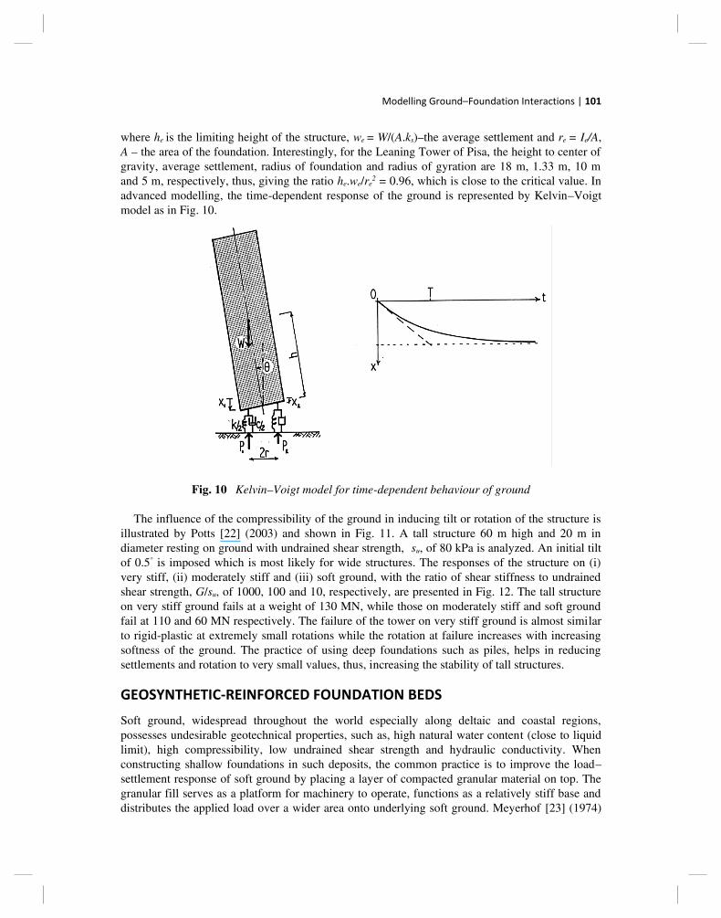
2 = 0.96, which is close to the critical value. In advanced modelling, the time-dependent response of the ground is represented by Kelvin–Voigt model as in Fig. 10.
Fig. 10 Kelvin–Voigt model for time-dependent behaviour of ground
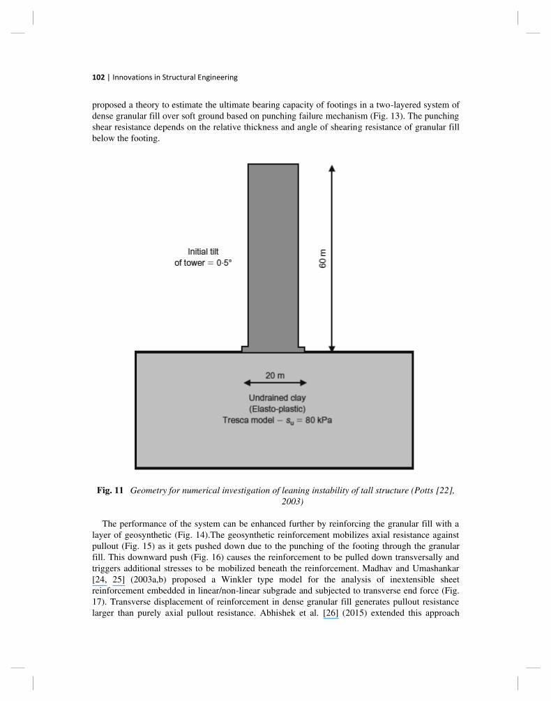
The influence of the compressibility of the ground in inducing tilt or rotation of the structure is illustrated by Potts [22] (2003) and shown in Fig. 11. A tall structure 60 m high and 20 m in diameter resting on ground with undrained shear strength, su, of 80 kPa is analyzed. An initial tilt of 0.5° is imposed which is most likely for wide structures. The responses of the structure on (i) very stiff, (ii) moderately stiff and (iii) soft ground, with the ratio of shear stiffness to undrained shear strength, G/su, of 1000, 100 and 10, respectively, are presented in Fig. 12. The tall structure on very stiff ground fails at a weight of 130 MN, while those on moderately stiff and soft ground fail at 110 and 60 MN respectively. The failure of the tower on very stiff ground is almost similar to rigid-plastic at extremely small rotations while the rotation at failure increases with increasing softness of the ground. The practice of using deep foundations such as piles, helps in reducing settlements and rotation to very small values, thus, increasing the stability of tall structures.
GEOSYNTHETIC-REINFORCED FOUNDATION BEDS
Soft ground, widespread throughout the world especially along deltaic and coastal regions, possesses undesirable geotechnical properties, such as, high natural water content (close to liquid limit), high compressibility, low undrained shear strength and hydraulic conductivity. When constructing shallow foundations in such deposits, the common practice is to improve the load–settlement response of soft ground by placing a layer of compacted granular material on top. The granular fill serves as a platform for machinery to operate, functions as a relatively stiff base and distributes the applied load over a wider area onto underlying soft ground. Meyerhof [23] (1974)
102 | Innovations in Structural Engineering
proposed a theory to estimate the ultimate bearing capacity of footings in a two-layered system of dense granular fill over soft ground based on punching failure mechanism (Fig. 13). The punching shear resistance depends on the relative thickness and angle of shearing resistance of granular fill below the footing.
Fig. 11 Geometry for numerical investigation of leaning instability of tall structure (Potts [22], 2003)
The performance of the system can be enhanced further by reinforcing the granular fill with a layer of geosynthetic (Fig. 14).The geosynthetic reinforcement mobilizes axial resistance against pullout (Fig. 15) as it gets pushed down due to the punching of the footing through the granular fill. This downward push (Fig. 16) causes the reinforcement to be pulled down transversally and triggers additional stresses to be mobilized beneath the reinforcement. Madhav and Umashankar [24, 25] (2003a,b) proposed a Winkler type model for the analysis of inextensible sheet reinforcement embedded in linear/non-linear subgrade and subjected to transverse end force (Fig. 17). Transverse displacement of reinforcement in dense granular fill generates pullout resistance larger than purely axial pullout resistance. Abhishek et al. [26] (2015) extended this approach

Modelling Ground–Foundation Interactions | 103
further to model a strip footing in a geosynthetic-reinforced foundation bed over soft, compressible ground stabilized with granular trench. The transverse resistance mobilized by the reinforcement increases the bearing capacity of the footing over and above the contribution by axial resistance alone.
Fig. 12 Rotation of tall structure with increase in its weight (Potts [22], 2003)
Fig. 13 Failure mechanism for footing in dense sand over soft clay (Meyerhof [23], 1974)
Fig. 14 Schematic of footing on geosynthetic-reinforced foundation bed over soft compressible ground

104 | Innovations in Structural Engineering
Fig. 15 Mechanism of axial pullout resistance by geosynthetic (Abhishek etal. [26], 2015)
Fig. 16 Forces due to transverse displacement of geosynthetic (Abhishek etal. [26], 2015)
Fig. 17 Schematic of (a) reinforcement subjected to transverse force, (b) mechanical model, (c) deformed profile and (d) forces on an element of reinforcement (Madhav and
Umashankar [24,25], 2003a, b)

Modelling Ground–Foundation Interactions | 105
CONCLUDING REMARKS
Structure–Foundation–Ground interaction is one unique field or topic which concerns both structural and geotechnical engineers. The importance of the topic can never be over-emphasized. Most geotechnical problems are very sensitive to foundation geometry (length, diameter, spacing), flexural stiffness, etc. Even basic parameters such as bearing capacity of shallow foundations, ultimate axial and lateral load capacities of deep/pile foundations, are influenced by the foundation characteristics. The paper summarizes basic modelling approaches for foundation–ground interactions, a leaning instability approach for tall structures on compressible ground, and analysis of geosynthetic-reinforced foundation beds. Consideration of height of tall structure rather than just the foundation leads to an interesting and unique failure state that is governed by stiffness of ground rather than strength.
REFERENCES
1. Madhav, M.R., “Ground versus Soil”, DFI of India News, Vol. 1, No. 3, Oct. 2015, pp. 1–16.
2. Terzaghi, K., “Theoretical Soil Mechanics”, John Wiley & Sons, NY, 1943.
3. Selvadurai, A.P.S., “Elastic Analysis of Soil – Foundation Interaction”, Developments in Geotechnical
Engineering, Elsevier Scientific Publishing Company, Vol. 17, 1979.
4. Lambe, T.W. and Whitman, R.V., “Soil Mechanics”, John Wiley & Sons, NY, 1969.
5. Winkler, E., “Die lehre von der elasticitaet and festigkeit”, Dominicus, Prague, 1867.
6. Kerr, A.D., “Elastic and Viscoelastic Foundation Models”, Journal of Applied Mechanics (Trans.
ASME), Vol. 31, 1964, pp. 491–498.
7. Hetenyi, M., “Beams and Plates on Elastic Foundations and Related Problems”, Applied Mechanics
Reviews, Vol. 19, No. 2, 1966, pp. 95–102.
8. Filonenko-Borodich, M.M., “Some Approximate Theories of the Elastic Foundation”, Uchenyie Zapiski
Moskovskogo Gosudarstvennogo Universiteta Mekhanica, Vol. 46, 1940, pp. 3–18.
9. Hetenyi, M., “Beams on Elastic Foundation: Theory with Applications in the Fields of Civil and
Mechanical Engineering”, University of Michigan Press, Ann Arbor, 1946.
10. Pasternak, P.L., “On a New Method of Analysis of an Elastic Foundation by Means of Two Foundation
Constants”, Gosudarstvennoe Izdatelstro Liberaturi po Stroitelstvui Arkhitekture, Moscow, 1954.
11. Reissner, E., “Deflection of Plates on Visco-elastic Foundation”, Journal of Applied Mechanics (Trans.
ASME), Vol. 80, 1958, pp. 144–145.
12. Vlazov, V.Z. and Leontiev, U.N., “Beams, Plates and Shells on Elastic Foundations”, Israel Program
for Scientific Translations, Jerusalem, 1966.
13. Madhav, M.R., “Modelling and Analysis in Geotechnical/Ground Engineering”, 20th IGS Annual
Lecture, Indian Geotechnical Journal, Vol. 28, No. 1, 1998, pp. 1–70.
14. Vlazov, V.Z., “Structural Mechanics of Thin-walled Three-dimensional Systems”, Gosstroiizdat,
Moscow, Leningrad, 1956a.
15. Vlazov, V.Z., “General Theory of Shells and its Application in Engineering”, Gosterkhizdat, Moscow,
Leningrad, 1956b.
16. Kerr, A.D., “A Study of a New Foundation Model”, Acta Mechanica, Vol. 1, No. 2, 1965, pp. 134–147.
17. Rhines, W.J., “Elastic-Plastic Foundation Model for Punch Shear Failure”, Journal of Soil Mechanics
and Foundations Division, ASCE, Vol. 95, No. SM3, 1969, pp. 819–828.
18. Hambly, E.C., “Soil Buckling and Leaning Instability of Tall Structures”, Journal of Structural
Engineering, Vol. 63A, No. 3, 1985, pp. 77–85.

106 | Innovations in Structural Engineering
19. Hambly, E.C., “Overturning Instability”, Journal of Geotechnical Engineering, ASCE, Vol. 116, No. 4,
1990, pp. 704–709.
20. Cheney, J.A., Abghari, A. and Kutter, B.L., “Stability of Leaning Towers”, Journal of Geotechnical
Engineering, ASCE, Vol. 117, No. 2, 1991, pp. 297–318.
21. Lancellotta, R., “Stability of a Rigid Column with Non-Linear Restraint”, Geotechnique, Vol. 43, No. 2,
1993, pp. 331–332.
22. Potts, D.M., “Numerical Analysis: A Virtual Dream or Practical Reality?”, Geotechnique, Vol. 53, No.
6, 2003, pp. 535–573.
23. Meyerhof, G.G., “Ultimate Bearing Capacity of Footings on Sand Layer Overlying Clay”, Canadian
Geotechnical Engineering, Vol. 11, No. 2, 1974, pp. 223–229.
24. Madhav, M.R. and Umashankar, B., “Analysis of Inextensible Sheet Reinforcement Subject to
Transverse Displacement/Force: Linear Subgrade Response”, Geotextiles and Geomembranes, Vol. 21,
No. 2, 2003a, pp. 69–84.
25. Madhav, M.R. and Umashankar, B., “Analysis of Inextensible Sheet Reinforcement Subject to
Downward Displacement/Force: Non-Linear Subgrade Response”, Geosynthetics International, Vol. 10,
No. 3, 2003b, pp. 95–102.
26. Abhishek, S.V., Rajyalakshmi, K. and Madhav, M.R., “Kinematics and Bearing Capacity of Strip
Footing on RFB over Compressible Ground Stabilized with Granular Trench”, Proc., 15th Asian
Regional Conference on Soil Mechanics and Geotechnical Conference, Fukuoka, Japan, Nov. 2015 (in
press).
All in-text references underlined in blue are linked to publications on ResearchGate, letting you access and read them immediately.