
Modelling and Control of a Power Electronic Cascade for ... file2. Model of the double stator...
12
- Modelling and Control of a Power Electronic Cascade for the Multi DC Bus Supply of a Three-Level NPC VSI D. Beriber 1 , A. Talha 1 , F. Bouchafaa 1 , M.S. Boucherit 2 and E.M. Berkouk 2 1 Laboratory of Instrumentation, Faculty of Electronics and Computer, University of Sciences and Technology Houari Boumediene, BP 32 El-Alia 16111 Bab-Ezzouar, Algiers, Algeria. Emails: [email protected], [email protected], [email protected]. 2 Polytechnic National School of Algiers, 10 roads Hassen Badi, El Harrach BP 182, Algiers, Algeria. Emails: [email protected], [email protected] Abstract. Voltage source multilevel inverters have become very attractive for power industries in power electronics applications during last years. The main purposes that have led to the development of the studies about multilevel inverters are the generation of output voltage signals with low harmonic distortion; the reduction of switching frequency. A serious constraint in a multilevel inverter is the capacitor voltage–balancing problem. The stability problem of the input DC voltages in a Three-Level Neutral Point Clamping (NPC) Voltage Source Inverter (VSI) is recalled and illustrated in this paper. Power structure is proposed. It consists in using one CV rectifiers but the instability of intermediary DC voltages is observed. To solve this problem the power structure is modified by adding clamping bridges across capacitors in order to limit their deviations. The obtained results are full of promise to be used to stabilise the input DC voltages of this converter. keywords. DSIM, Multilevel, NPC, VSI, Inverter, Clamping, Control, Modelling, Feedback. 1. Introduction The apparition of new power components controllable in the opened and closed states has let to the conception of new and fast converters for high power applications. Thus, drives have seen their cost decreasing considerably. The progress accomplished in the micro-computer tools has let the synthesis of more performing and robust control algorithms for machine drive.
Transcript of Modelling and Control of a Power Electronic Cascade for ... file2. Model of the double stator...

������������������� ���������������������� ��������������������������������������� � � �� �� � �� ��� � �� ��� � � � � � ��� � � � ��� � ��� � � −� � � ��
Modelling and Control of a Power Electronic Cascade for the Multi DC Bus
Supply of a Three-Level NPC VSI
D. Beriber1, A. Talha1, F. Bouchafaa1, M.S. Boucherit2 and E.M. Berkouk2
1Laboratory of Instrumentation, Faculty of Electronics and Computer, University of Sciences and Technology Houari Boumediene, BP 32 El-Alia 16111 Bab-Ezzouar, Algiers, Algeria.
Emails: [email protected], [email protected], [email protected]. 2 Polytechnic National School of Algiers, 10 roads Hassen Badi, El Harrach BP 182, Algiers,
Algeria. Emails: [email protected], [email protected]
Abstract. Voltage source multilevel inverters have become very attractive for power industries in power electronics applications during last years. The main purposes that have led to the development of the studies about multilevel inverters are the generation of output voltage signals with low harmonic distortion; the reduction of switching frequency. A serious constraint in a multilevel inverter is the capacitor voltage–balancing problem. The stability problem of the input DC voltages in a Three-Level Neutral Point Clamping (NPC) Voltage Source Inverter (VSI) is recalled and illustrated in this paper. Power structure is proposed. It consists in using one CV rectifiers but the instability of intermediary DC voltages is observed. To solve this problem the power structure is modified by adding clamping bridges across capacitors in order to limit their deviations. The obtained results are full of promise to be used to stabilise the input DC voltages of this converter.
keywords. DSIM, Multilevel, NPC, VSI, Inverter, Clamping, Control, Modelling, Feedback.
1. Introduction
The apparition of new power components controllable in the opened and closed states has let to the conception of new and fast converters for high power applications. Thus, drives have seen their cost decreasing considerably. The progress accomplished in the micro-computer tools has let the synthesis of more performing and robust control algorithms for machine drive.

Modelling and Control of a Power Electronic Cascade − M. Beriber et al. 685
High power applications in electrical traction require high voltage supply for motors. The only way to use multilevel converters is actually to generate voltages with high magnitudes [1], [2], [3]. These converters are built with a series connection of switches (Neutral Point Clamped Converters) or commutation cells (Flying Capacitor Converter) or full bridge converters (Cascaded multilevel converters). An additional advantage of multilevel converters is the Power Quality improvement of modulated voltages. Cheaper choke filters are then required. This paper deals with a Double Stator Induction Motors (DSIM) which is fed by a Three-Level NPC VSI. The critical problem of multilevel inverter is the deviation of capacitor voltages which are used in the multi DC bus for creating intermediary levels in modulated voltages. In the first part of this paper, we remind the model of the double stator induction motors [1], [2],[3]. Then, we elaborate the working model of this inverter, without presumption on its control [2], [3]. In the second part, we develop the space vector modulation strategy to control this inverter [2], [3]. In this part, the inverter is fed by constant input DC voltages. In the last part, we study the stability problem of the input DC voltages of the inverter. Thus, we study a cascade constituted by two three-level PWM rectifiers – two three-level NPC VSI – half clamping bridge – DSIM [3]. The results obtained show that the input DC voltages of the inverter are not stables. To improve the performances of the proposed cascade and stabilise the input DC voltages, the authors propose in this paper a solution which uses feedback for this cascade. The results obtained confirm the good performances of the proposed solution.
2. Model of the double stator induction machines
The model of the double stator induction machines (DSIM) is given by figure1.
Fig.1. DSIM schema
� � � ���IJ-STA, Volume 2, N°2, December 2008.
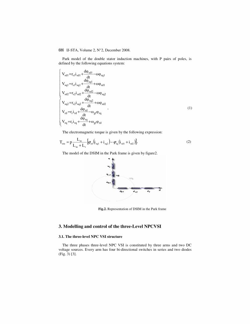
Park model of the double stator induction machines, with P pairs of poles, is defined by the following equations system:
�������
�
�������
�
�
++=
−+=
++=
−+=
++=
−+=
rdglrq
rqrrq
rqglrd
rdrrd
sd2sq2
sq2s2sq2
sq2sd2
sd2s2sd2
sd1sq1
sq1s1sq1
sq1sd1
sd1s1sd1
��dt
d�irV
��dt
d�irV
��dt
d�irV
��dt
d�irV
��dt
d�irV
��dt
d�irV
, (1)
The electromagnetic torque is given by the following expression:
( ) ( )[ ]sd2sd1rqsq2sq1rdrm
mem iiii
LLL
pT +−++
= ϕϕ , (2)
The model of the DSIM in the Park frame is given by figure2.
3. Modelling and control of the three-Level NPCVSI
3.1. The three-level NPC VSI structure The three phases three-level NPC VSI is constituted by three arms and two DC
voltage sources. Every arm has four bi-directional switches in series and two diodes (Fig. 3) [3].
Fig.2. Representation of DSIM in the Park frame

Modelling and Control of a Power Electronic Cascade − M. Beriber et al. 687
3.2. Knowledge model
The switch connection function FKs indicates the opened or closed state of the switch TDKs.
We define too a half arm connection function bkmF with:
k : arm number.
���
=arm halfupper for the 1
arm halflower for the 0m
For an arm k of the three-phase three-level NPC VSI, several complementary laws
controls are possible. The control law which lets an optimal control of this inverter is [3]:
���
==
K2K3
K1K4
BB
BB, (3)
Where BKs represents the gate control of the switch TKs. We define the half arm connection function b
i1F and bi0F associated respectively to the upper and lower half
arms. Where i is arm number (i∈{1, 2, 3}).
��
���
=
=��
���
=
=��
���
=
=
3433b30
3231b31
2423b20
2221b21
1413b
10
1211b
11
FFF
FFF;
FFF
FFF;
FFF
FFF, (4)
id1
D21 T21
D24 T24
T23 D23
TK22 D22
D31 T31
D34 T34
T32 D32
T33 D33
T12
T11 D11
T14 D14
D12
T13 D13
VB VC VA
DD30 DD10 DD20
DD11 DD21 DD31 UC1
UC2
id2
iA iB iC M
A B id0
C
Fig.3. The three-level NPC inverter

� � � ���IJ-STA, Volume 2, N°2, December 2008.
The output voltages of the inverter relatively to the middle point M are defined as follows:
C2b
30
b20
b10
C1b
31
b21
b11
CM
BM
AM
UFFF
UFFF
VVV
���
�
�
���
−���
�
�
���
=���
�
�
���
, (5)
The system (5) shows that the three-level NPC VSI can be considered as two two-level voltage source inverters in series.
The input currents of the inverter are given as follow:
��
���
++=
++=
3b
302b201
b10d2
3b
312b
211b
11d1
iFiFiFi
iFiFiFi, (6)
The current id0 is defined by the following relation:
( ) ( )d2d1321d0 iiiiii +−++= , (7)
3.3. PWM strategy of the three-level NPC VSI
The inverter is controlled by the space vector modulation strategy which uses two bipolar carriers.
This strategy is characterised by two parameters [2]: - Modulation index m defined as ratio between the carrier frequency fp and the
reference voltage frequency: ��
��
=
f
fm p .
- Modulation rate r is the ratio between the magnitude Vm of the reference voltage and three times of the carriers magnitude Upm:
���
�
��
=
pm
m
UV
r .
The figure4 shows the signals of this strategy.
For even values of m, the output voltages present symmetry relatively to the quarter
Fig.4. Space vector modulation strategy (m=6, r=0.8)

Modelling and Control of a Power Electronic Cascade − M. Beriber et al. 689
ia2
ib2
ic2
id12
id10
id11
C12
C11
Irect12
Urect12 Inet 11
Inet 12
Inet 13
RL
RL
RL
Vnet 11
Vnet 12
Vnet 13
Three level
PWM
rectifier n°1
id21
id20 C22
DSIM
Three level
NPC
voltage
source
inverter
n°1
id22 C21
Three level
NPC
voltage
source
inverter
n°2
ia1 ib1
ic1
Uc 12
Uc 11
Uc 22
Uc 21
Inet 21
Inet 22
Inet 23
RL
RL
RL
Vnet 21
Vnet 22
Vnet 23
Three level
PWM
rectifier n°2
Urect11
Urect22
Urect21
Irect11
Irect22
Irect21
of the period. Then, only odd harmonics exist. These harmonics gather by families centred around frequencies multiple of 2mf. The first family centred around frequency 2mf is the most important in view of its magnitude (Fig. 5).
4. Two three - level PWM rectifiers-filter – two three - level NPC VSI - DSIM cascade
Until now, we have supposed the input DC voltages of the three-level NPC VSI constants. In this part, we study a generation input DC voltages technique [3]. For this, we propose a cascade constituted by two three -level PWM rectifiers-filter-two three-level NPC VSI which feeds DSIM (Fig. 6). This cascade lets to absorb, in network, sinusoidal input currents with unity power factor.
All
0 0.005 0.01 0.015 0.02
-400
-200
0
200
400
Va
(V)
t(s)
Fig.5. Simple voltage of the inverter and its spectrum (m=27)
Fig.6. Two three-level PWM rectifiers-filter-two three-level NPC VSI-DSIM cascade

� � � ���IJ-STA, Volume 2, N°2, December 2008.
control strategies used for the two-level inverter can be used for the two-level PWM rectifier [3]. In this paper, they use the current hysteresis strategy to control this rectifier.
4.1. Modelling of the intermediate filter
The model of the intermediate filter is defined by the following system:
����
�
����
�
�
−=
+=
−=
+=
d21rect22c22
22
d22rect21c21
21
d12rect12c12
12
d11rect11c11
11
iIdt
dUC
iIdt
dUC
iIdt
dUC
iIdt
dUC
, (8)
We note: Urect1=Urect11+Urect12; and Urect2=Urect21+Urect22.
4.2. Simulation results
The parameters of the intermediate filter are: C11=C12=C21=C22=10mf. The battery voltage is initialized at Uc11=Uc12=Uc21=Uc22=200V.
The different input voltages of the VSI are not stables and their differences are not null (Fig. 7). The output voltages of the two three-level rectifiers decrease continually (Fig. 8).
Fig.7. Input DC voltages of the two three-level NPC VSI

Modelling and Control of a Power Electronic Cascade − M. Beriber et al. 691
5. The half clamping bridge
To improve the input voltages of the three-level NPC inverter, we propose to use a half clamping bridge, constituted by a transistor and a resistor [3]. The transistors are controlled to maintain equal the different input DC voltages of the inverter (Fig. 9).
5.1. Modelling of the intermediate filter
Figure10 shows the structure of the intermediate filter of the studied cascade.
The model of the half clamping bridge-filter set is defined by the following
equation:
���
���
�
−=
−−=
dK2rectKCK2
K2
ridK1rectKCK1
K1
IIdt
dUC
IIIdt
dUC , (9)
Fig.8. Input DC voltages of two the three-level NPC VSI
idi
Rpi
Ti
id(i-1)
Uci
ici
ic(i+1)
Ci
ic(i-1)
ir(i+1)
ir(i-1)
Irect(i-1)
Irect(i+1) iri
Fig.9. Clamping bridge cell Fig.10. Structure of the intermediate filter of the of the half clamping bridge cascade
IrectK1
IrectK2
idK0
idK1
CK2
CK1i
riTKiRp
UrectK2
UcK1
UcK2
UrectK1
idK2

� � � ���IJ-STA, Volume 2, N°2, December 2008.
Where Rp
UI CK1
ri = , (10)
With: i=1 for the first filter. i=2 for the second filter.
The control algorithm of the resistive clamping circuits can be summarized as follows:
If UcK1 > UrectK1 � (TK1=1) & (TK2=0)
5.2. Simulation results
We note that the input voltage of two three-level NPC VSI (Uc11, Uc12, Uc21 and Uc22) become practically equals in bench regime and their differences are decreased to have a value practically null in steady state (Fig. 11). The output voltage of the two three-level are lightly increased (Fig. 12).
6. Three -level PWm rectifier feedback
In the previous part, we well-dressed obviousness the stability problem of the input DC voltages of the three-level NPC VSI. For resolve this problem, we propose the using the bridge clamping, because this bridge allow improve the input voltage of three-level inverter. In spite of this solution, the out put voltage of rectifier is not constant. For remedy of this problem, we propose the feedback of the input voltages of the three-level. The feedback low not only enslaves the input voltages of the inverter but as using a reasonable value of capacitors C1 and C2.
Fig.11. Clamping bridge voltage and their differences

Modelling and Control of a Power Electronic Cascade − M. Beriber et al. 693
6.1. Voltage boucle model
The modelling of this boucle is based on principle of instantaneous power conservation with no loss hypothesis. This boucle imposes efficacy network reference current.
The input power is calculated as:
�=
−−=3
1k
2netk2
netknetknetk )dt
di2L
Rii(VPe , (11)
The output power is calculated as:
rectrect
2
1irectirecti IU2)I(UPe �
=
== , (12)
By neglecting Joule losses and assuming sinusoidal grid currents, we get:
rectceeff I2UI3E = , (13)
Where Eeff is the rms value of grid voltages and Ie is the rms value of grid currents. Uc is the constant value of the DC capacitor voltage and Irect is the DC current. A IP regulator is used to regulate the DC voltage. The general principle feedback of three-level rectifier is shown on figure13.
Three-level rectifier
controlled by current
hysteretic
Uref iload
icref
Irect +-
Iload Uc
+ -
ic ieref - +
s.C1
pK
sKi
3Eeff
2Uc
Fig.13. Enslavement algorithm of output voltage of three-level rectifier
Fig.12. The input voltage of the clamping bridge
� � � ���IJ-STA, Volume 2, N°2, December 2008.
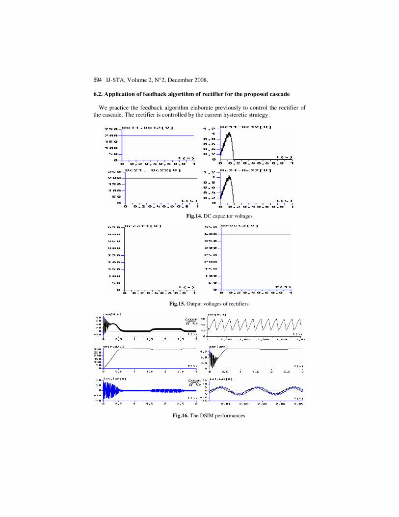
6.2. Application of feedback algorithm of rectifier for the proposed cascade
We practice the feedback algorithm elaborate previously to control the rectifier of the cascade. The rectifier is controlled by the current hysteretic strategy
Fig.16. The DSIM performances
Fig.15. Output voltages of rectifiers
Fig.14. DC capacitor voltages

Modelling and Control of a Power Electronic Cascade − M. Beriber et al. 695
DC capacitor voltages are practically equal (Fig. 14). The controlled voltages of rectifiers are constant (Fig. 15). The performance of the speed control algorithm of the DSIM shows that the current of the machine nearly is sinusoidal. The speed and the torque effect for the charge variation between two instants t=1.5s and t=2.5s (Fig. 16).
7. Conclusion
In this paper we have proposed one power structure in order to stabilize intermediary DC voltages of a three-level NPC inverter. This power structure has been modelled and the control part has been explained.
The using of a half clamping bridge has allowed us to equalize the different input DC voltages of the inverter. In spite of this solution, the out put voltage of rectifier is not constant. For remedy of this problem, we propose to use the feedback algorithm of the output voltage of rectifier. The obtained simulated results show that the proposed solution is very efficient to solve the instability problem of the multilevel inverter.
References
1. D. Hadiouche, H. Razik, A. Rezzoug, "Study and simulation of space vector PWM control of double-star induction motors", IEEE-CIEP’2000, Acapulco, Mexico, pp. 42-47.
2. A. Monti, A. P. Morando, L. Resta, M. Riva, "Comparing two level GTO-inverter feeding a double-stator asynchronous motor with a three level GTO-inverter feeding a single star asynchronous motor", EPE’1995, Sevilla, Spain, pp. 2419-2425.
3. D. Beriber, M. Berkouk, A. Talha, M. O. Mahmoudi, "Study and Control of Two Two–Level PWM rectifiers–Clamping Bridge–Two Three Level NPC VSI Cascade. Application to Double Stator Induction Machine", IEEE 35th Power Electronics Specialists Conference, PESC’2004, Aachen, Germany 2004, pp. 3894-3899.


![Linear Induction Motorcegt201.bradley.edu/projects/proj2016/lim...•Linear to Rotary Model •0.4572 [m] diameter •0.3048 [m] arbitrary stator length •Stator contour designed](https://static.fdocuments.in/doc/165x107/5f9836bee9786d1ce51804db/linear-induction-alinear-to-rotary-model-a04572-m-diameter-a03048.jpg)


