
MODELING WITH UML - INTRODUCTION UML offers a well defined syntax (for object...
66
MODELING WITH UML - INTRODUCTION UML offers a well defined syntax (for object representation/description), well defined semantics (to foster common understanding of notation), and well suited (in broadly describing all aspects of systems under discourse). That is, it is a unified modeling language. ISSUES: The concept of modeling objects using UML notations (five key graphical syntactic notations) Notations: Use Cases, Class Diagrams, Sequence, Diagrams, Statechart Diagrams, Activity Diagrams, plus management notations: Component and Deployment Diagrams Environment or CASE for UML object modeling (Rational Rose and Real-Time Rational Rose) Background of UML: Origins in OMT, Booch, OOSE, etc. plus Harel’s state diagrams SYSTEM MODELS (in UML notation) Functional Model – use case diagrams (synthesized from ‘scenarios’ – from phenomena and concepts) Object Model – class diagrams (representing object structures as objects, attributes, associations, and operations) Dynamic Model – sequence diagrams, statechart diagrams and activity diagrams (describe the internal behavior or finite state machine of the system). SD are inter-object messaging and interactions, while SC-diagrams depict the finite state machine description of an object’s behavior
-
Upload
francis-perry -
Category
Documents
-
view
226 -
download
0
Transcript of MODELING WITH UML - INTRODUCTION UML offers a well defined syntax (for object...
MODELING WITH UML - INTRODUCTION
UML offers a well defined syntax (for object representation/description), well defined semantics
(to foster common understanding of notation), and well suited (in broadly describing all aspects of systems under discourse). That is, it is a unified modeling language.
ISSUES: The concept of modeling objects using UML notations (five key graphical syntactic
notations) Notations: Use Cases, Class Diagrams, Sequence, Diagrams, Statechart Diagrams, Activity
Diagrams, plus management notations: Component and Deployment Diagrams Environment or CASE for UML object modeling (Rational Rose and Real-Time Rational Rose) Background of UML: Origins in OMT, Booch, OOSE, etc. plus Harel’s state diagrams
SYSTEM MODELS (in UML notation) Functional Model – use case diagrams (synthesized from ‘scenarios’ – from phenomena and
concepts) Object Model – class diagrams (representing object structures as objects, attributes,
associations, and operations) Dynamic Model – sequence diagrams, statechart diagrams and activity diagrams (describe
the internal behavior or finite state machine of the system). SD are inter-object messaging and interactions, while SC-diagrams depict the finite state machine description of an object’s behavior
2.2: UML OVERVIEW - USE CASE DIAGRAMS
DESCRIBE SYSTEM FUNCTIONALITY FROM EXTERNAL VIEW, UML Use Cases provide the notation for eliciting and analyzing the functionality
ACTORS (entities: users, other systems, the operating environment) ARE ENTITIES EXTERNAL TO AND INTERACT WITH THE SYSTEM FUNCTIONALITY (The Use Cases)
THE SYSTEM’S BOUNDARY IS DEFINED BY THE ACTORS AND THE USE CASES – THE INTERNALS (represented by the Use Cases) AND THE EXTERNAL (represented by the Actors)
USE CASE DIAGRAMS – Notation for representing the Use Cases, Actors, and the Boundary. The Relationship between the Use Cases and the Actors is represented by the LINKS (or lines)
(Fig 2-1)
WatchUser WatchRepairPerson
ReadTime
SetTime
ChangeBattery
SimpleWatch
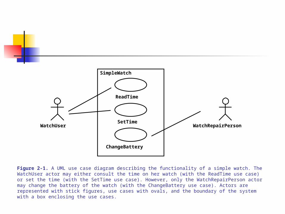
Figure 2-1. A UML use case diagram describing the functionality of a simple watch. The WatchUser actor may either consult the time on her watch (with the ReadTime use case) or set the time (with the SetTime use case). However, only the WatchRepairPerson actor may change the battery of the watch (with the ChangeBattery use case). Actors are represented with stick figures, use cases with ovals, and the boundary of the system with a box enclosing the use cases.
CLASS DIAGRAMS
NOTATION FOR DESCRIBING SYSTEM STRUCTURE EACH CLASS IS AN ABSTRACTION (Containment) OF A SET OF RELATED OBJECTS CLASSES ARE ‘LINKED’ THROUGH ASSOCIATION, AND OBJECTS ARE INSTANCES
OF CLASSES CLASS DIAGRAMS ARE SPECIFIED IN TERMS OF:
objects, classes, attributes, operations, and associations CLASSES ARE INTERCONNECTED BY ASSOCIATIONS (labeled links)
The numbers, called MULTIPLICITIES, at the two ends of the link indicate the number of associations/relationships between the pair of linked classes
EACH CLASS IS GRAPHICALLY REPRESENTED AS A RECTANGLE OF 3 COMPARTMENTS:
The class-name, The object-attributes, The object-methods
(Fig 2-2)

Figure 2-2. A UML class diagram describing the elements of a simple watch.
1
2
1
1
1
1
1
2
SimpleWatch
Display Battery TimePushButton
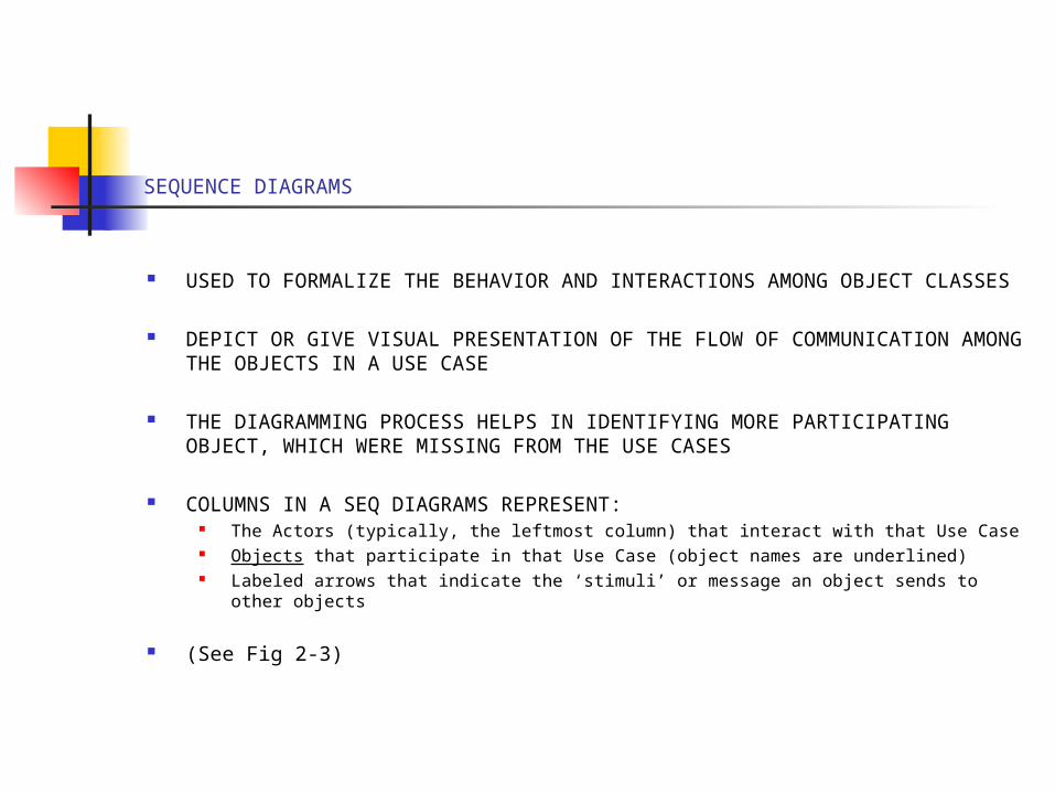
SEQUENCE DIAGRAMS
USED TO FORMALIZE THE BEHAVIOR AND INTERACTIONS AMONG OBJECT CLASSES
DEPICT OR GIVE VISUAL PRESENTATION OF THE FLOW OF COMMUNICATION AMONG THE OBJECTS IN A USE CASE
THE DIAGRAMMING PROCESS HELPS IN IDENTIFYING MORE PARTICIPATING OBJECT, WHICH WERE MISSING FROM THE USE CASES
COLUMNS IN A SEQ DIAGRAMS REPRESENT: The Actors (typically, the leftmost column) that interact with that Use Case Objects that participate in that Use Case (object names are underlined) Labeled arrows that indicate the ‘stimuli’ or message an object sends to other objects
(See Fig 2-3)
:SimpleWatch :Time:Display
pressButton1() blinkHours()
blinkMinutes()
pressButton2() incrementMinutes()
refresh()
pressButtons1And2()commitNewTime()
stopBlinking()
pressButton1()
:WatchUser
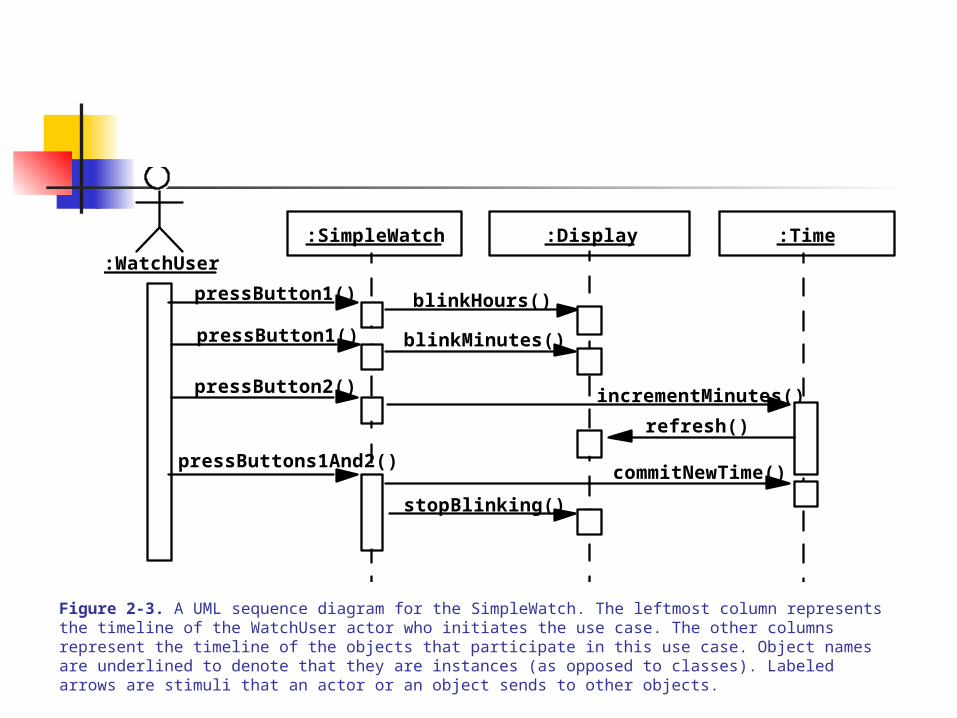
Figure 2-3. A UML sequence diagram for the SimpleWatch. The leftmost column represents the timeline of the WatchUser actor who initiates the use case. The other columns represent the timeline of the objects that participate in this use case. Object names are underlined to denote that they are instances (as opposed to classes). Labeled arrows are stimuli that an actor or an object sends to other objects.
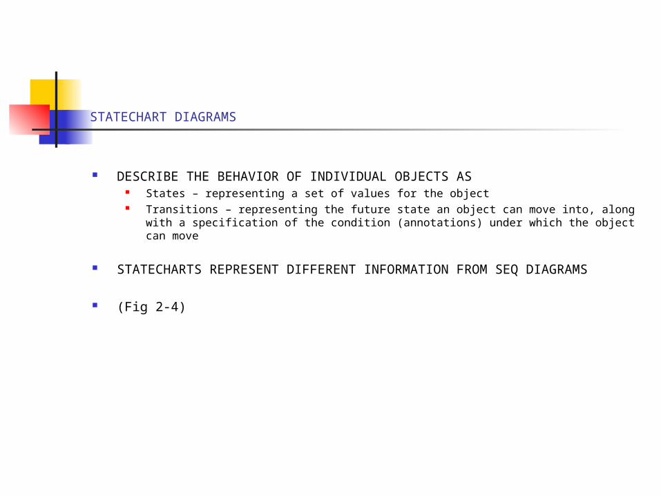
STATECHART DIAGRAMS
DESCRIBE THE BEHAVIOR OF INDIVIDUAL OBJECTS AS States – representing a set of values for the object Transitions – representing the future state an object can move into, along with a
specification of the condition (annotations) under which the object can move
STATECHARTS REPRESENT DIFFERENT INFORMATION FROM SEQ DIAGRAMS
(Fig 2-4)
button1&2Pressed
button1Pressed
button2Pressed
button2Pressed
button2Pressed
button1Pressed
button1&2Pressed IncrementMinutes
IncrementHours
BlinkHours
BlinkSeconds
BlinkMinutes
IncrementSeconds
StopBlinking
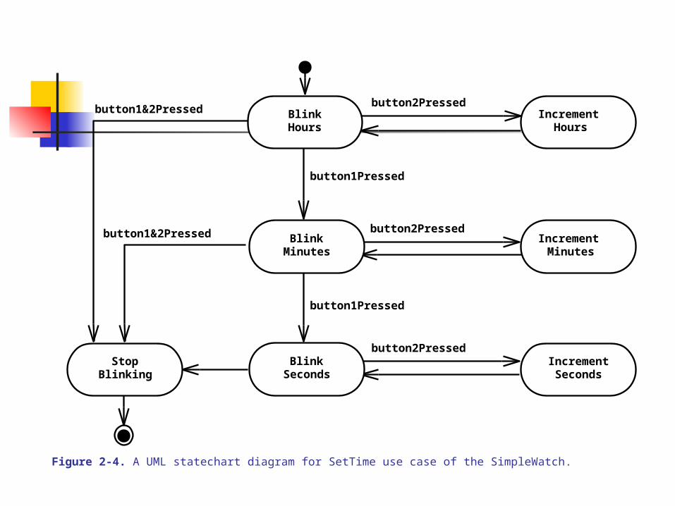
Figure 2-4. A UML statechart diagram for SetTime use case of the SimpleWatch.
ACTIVITY DIAGRAMS
ACTIVITIES ARE STATES THAT REPRESENT THE EXECUTION OF A SET OF OPERATIONS
STATES ARE CONNECTED BY TRANSITIONS, REPRESENTING CONTROL FLOW; AND ‘THICK’ RECTANGULAR BARS, REPRESENTING SYNCHRONIZATION POINTS
SEQUENCE AND CONCURRENT ACTIVITIES (and ‘Swimlanes’) CAN BE DESCRIBED
(See Fig 2-5)
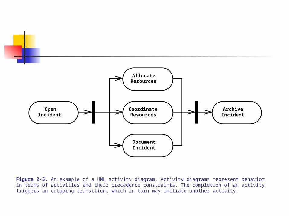
OpenIncident
AllocateResources
CoordinateResources
DocumentIncident
ArchiveIncident
Figure 2-5. An example of a UML activity diagram. Activity diagrams represent behavior in terms of activities and their precedence constraints. The completion of an activity triggers an outgoing transition, which in turn may initiate another activity.

2.3: MODELING CONCEPTS
OBJECT-ORIENTED MODELING – Building an abstraction of a system as a model of objects
CONCEPTS System – An organized set of communicating parts for a purpose (Watch components for
time, Car components for transportation, Payroll software components for preparing employees’ pay)
Subsystem – A recursively defined subset of a system, whose atomic parts are objects, performs a sub-function of the system (Engine of a Car, The Display unit of a Watch)
Modeling – Constructing a structure for complexly interconnected subsystems of a system. The modeling process is guided by
abstraction (I.e., deference of details), divide-and-conquer, ignoring the irrelevant
E.g., modeling an airplane with subsystems: flight simulator, instrument panel, exterior layout, engine
(Fig 2-6)
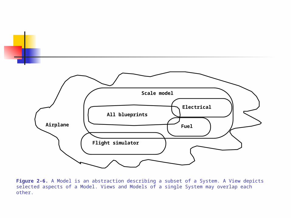
Airplane
All blueprints
Scale model
Electrical
Fuel
Flight simulator
Figure 2-6. A Model is an abstraction describing a subset of a System. A View depicts selected aspects of a Model. Views and Models of a single System may overlap each other.

MORE CONCEPTS
VIEW – A specific focus of a (sub)model on current interest, enough to understand by one person
NOTATIONS – Graphical or textual rules (syntax) for representing views (E.g., UML class diagram notation)
UML diagramming notations focus on Classes, Events, States, Interactions, Activities
Fig 2-7 & Fig 2-8
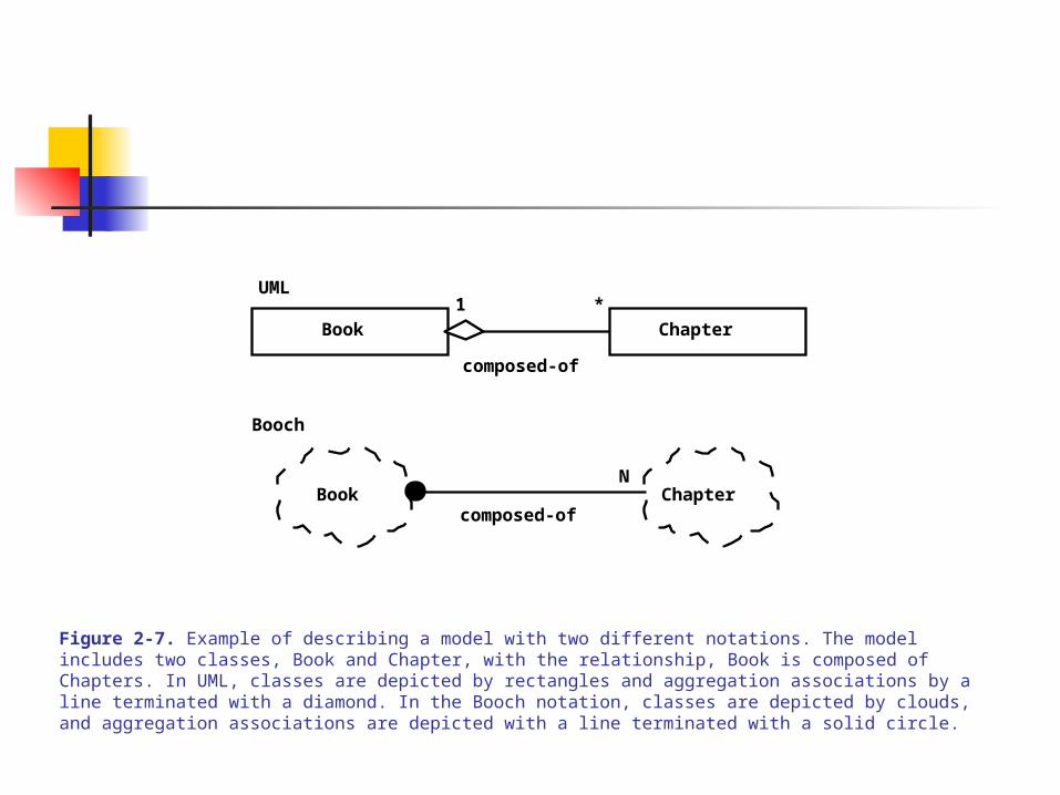
Book ChapterN
composed-of
Booch
Book Chapter
composed-of
UML1 *
Figure 2-7. Example of describing a model with two different notations. The model includes two classes, Book and Chapter, with the relationship, Book is composed of Chapters. In UML, classes are depicted by rectangles and aggregation associations by a line terminated with a diamond. In the Booch notation, classes are depicted by clouds, and aggregation associations are depicted with a line terminated with a solid circle.
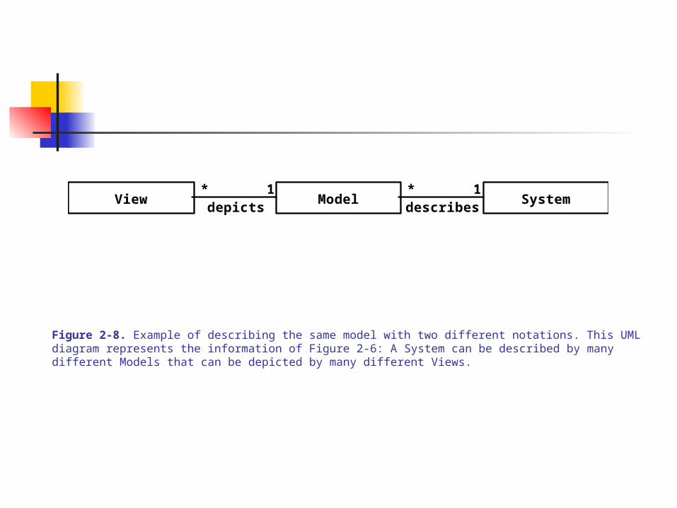
View Model System**describesdepicts
1 1
Figure 2-8. Example of describing the same model with two different notations. This UML diagram represents the information of Figure 2-6: A System can be described by many different Models that can be depicted by many different Views.

CONCEPTS, PHENOMENA, MODELING PROCESS
PHENOMENON – A perceived object or idea or entity or fact or occurrence CONCEPT – An unifying description, which abstractly describes a set of
phenomena (as a collective object or idea or entity or fact or occurrence)
A Concept also describes the common attributes of the set A Concept has 1) a name 2) purpose or properties and 3) membership – the phenomena
ABSTRACTION – The classification of phenomena into concepts MODELING – Development or construction of abstractions (with deferred details)
(E.g., the periodic table of atoms, biological classification) A model may be constructed prior to the concept/phenomena it represents (.e.g., new
theories)
(See Fig 2-9)

Name Purpose Members
Clock A device thatmeasures time.
Figure 2-9. The three components of the Clock concept: name, purpose, and members.
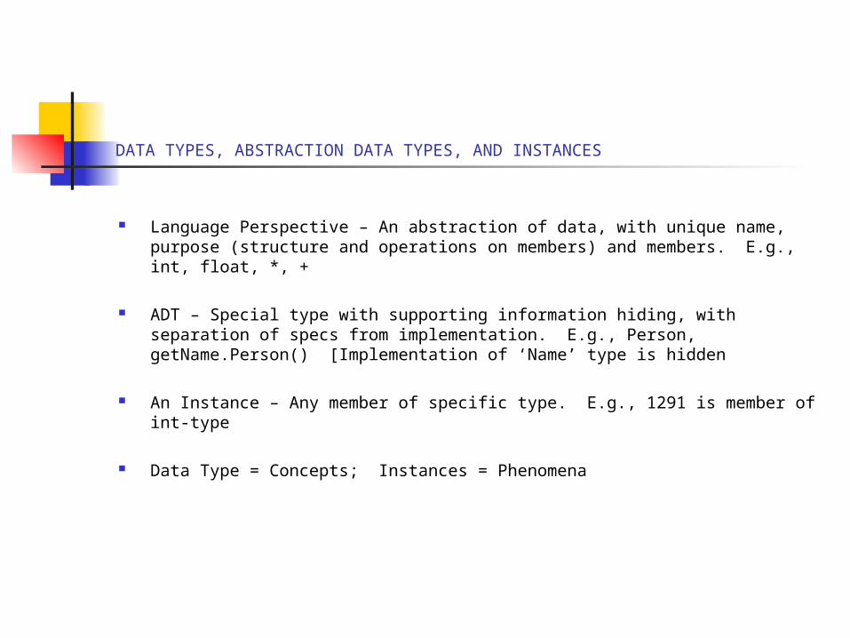
DATA TYPES, ABSTRACTION DATA TYPES, AND INSTANCES
Language Perspective – An abstraction of data, with unique name, purpose (structure and operations on members) and members. E.g., int, float, *, +
ADT – Special type with supporting information hiding, with separation of specs from implementation. E.g., Person, getName.Person() [Implementation of ‘Name’ type is hidden
An Instance – Any member of specific type. E.g., 1291 is member of int-type
Data Type = Concepts; Instances = Phenomena
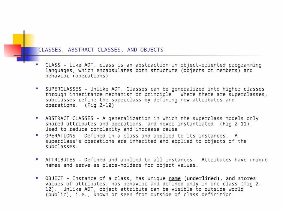
CLASSES, ABSTRACT CLASSES, AND OBJECTS
CLASS – Like ADT, class is an abstraction in object-oriented programming languages, which encapsulates both structure (objects or members) and behavior (operations)
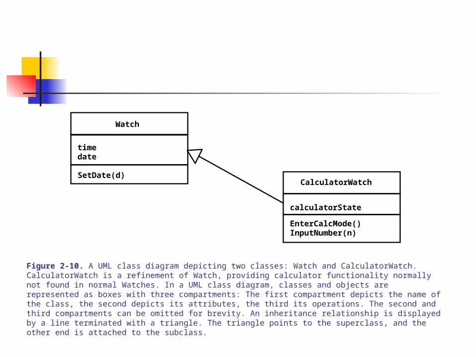
SUPERCLASSES – Unlike ADT, Classes can be generalized into higher classes through inheritance mechanism or principle. Where there are superclasses, subclasses refine the superclass by defining new attributes and operations. (Fig 2-10)
ABSTRACT CLASSES – A generalization in which the superclass models only shared attributes and operations, and never instantiated (Fig 2-11). Used to reduce complexity and increase reuse
OPERATIONS – Defined in a class and applied to its instances. A superclass’s operations are inherited and applied to objects of the subclasses.
ATTRIBUTES – Defined and applied to all instances. Attributes have unique names and serve as place-holders for object values.
OBJECT – Instance of a class, has unique name (underlined), and stores values of attributes, has behavior and defined only in one class (fig 2-12). Unlike ADT, object attribute can be visible to outside world (public), i.e., known or seen from outside of class definition
Watch
timedate
CalculatorWatchSetDate(d)
EnterCalcMode()InputNumber(n)
calculatorState
Figure 2-10. A UML class diagram depicting two classes: Watch and CalculatorWatch. CalculatorWatch is a refinement of Watch, providing calculator functionality normally not found in normal Watches. In a UML class diagram, classes and objects are represented as boxes with three compartments: The first compartment depicts the name of the class, the second depicts its attributes, the third its operations. The second and third compartments can be omitted for brevity. An inheritance relationship is displayed by a line terminated with a triangle. The triangle points to the superclass, and the other end is attached to the subclass.
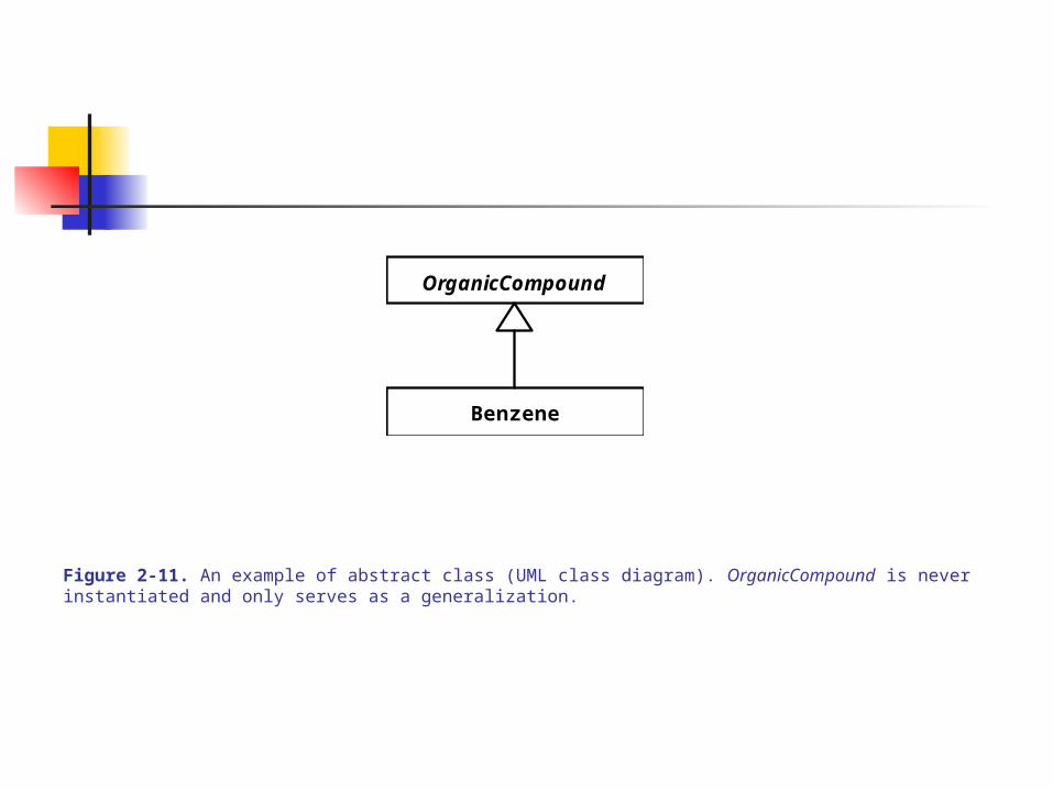
OrganicCompound
Benzene
Figure 2-11. An example of abstract class (UML class diagram). OrganicCompound is never instantiated and only serves as a generalization.
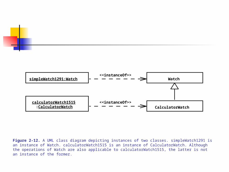
Watch
CalculatorWatch
simpleWatch1291:Watch
calculatorWatch1515:CalculatorWatch
<<instanceOf>>
<<instanceOf>>
Figure 2-12. A UML class diagram depicting instances of two classes. simpleWatch1291 is an instance of Watch. calculatorWatch1515 is an instance of CalculatorWatch. Although the operations of Watch are also applicable to calculatorWatch1515, the latter is not an instance of the former.
EVENTS CLASSES, EVENTS, AND MESSAGES
EVENT CLASS – An abstraction of a kind of event for which the system has a common response
EVENT – Instance of an event class, a stimulus, or relevance occurrence, which needs a response
MESSAGE – A mechanism for conveying or transmitting signals that create a stimulus or an occurrence from a sending/requesting object to a receiving object. The receiving object executes its operation to provide a service requested by the sending object. Message may contain arguments, which define the protocol of the communication (Fig 2-13)

pressButton2()getTime()
getTimeDelta()
:WatchUser
GMTTime
GMTTime
:SimpleWatch :TimeZone:Time
Figure 2-13. Examples of message sends (UML sequence diagram). The Watch object sends the getTime() message to a Time object to query the current Greenwich time. It then sends the getTimeDelta() message to a TimeZone objects to query the difference to add to the Greenwich time. The dashed arrows represent the results that are sent back to the message sender.
OBJECT-ORIENTED MODELING & PROTOTYPING USING FALSIFICATION/SIMPLIFICATION
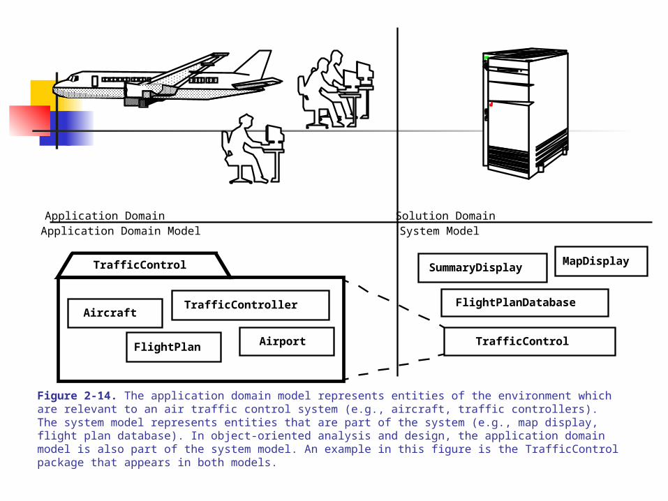
APPLICATION DOMAIN – The user’s physical environment including users, people, work processes, and all associated dynamics or changes over time
SOLUTION DOMAIN – Space of all possible solutions, and all the possible changes due to changes in technological enablers. This is modeled as the system design and object design activities of the software process
OO ANALYSIS – Focuses on modeling the application domain (using objects & classes) OO DESIGN – Focuses on modeling the solution domain (using objects and classes) SYSTEM MODEL – Comprises the application domain model + solution domain model (OO UNIFORMITY – Using OO paradigm for both Application and Solution domain
modeling fosters: traceability, class encapsulation into subsystems/decomposition, and reusability
PROTOTYPING – Removal of irrelevant/details to simplify modeling (assumptions falsify the conceptual model, and refined or validated through evolutionary modeling or feedback)
Fig 2-14)
Application Domain Solution DomainApplication Domain Model System Model
AircraftTrafficController
FlightPlan Airport
MapDisplay
FlightPlanDatabase
SummaryDisplay
TrafficControl
TrafficControl
Figure 2-14. The application domain model represents entities of the environment which are relevant to an air traffic control system (e.g., aircraft, traffic controllers). The system model represents entities that are part of the system (e.g., map display, flight plan database). In object-oriented analysis and design, the application domain model is also part of the system model. An example in this figure is the TrafficControl package that appears in both models.

2.4: UML DIAGRAMS – IN DEPTH
USE CASE DIAGRAMS – Represent system functionality from user perspectives and define the system’s boundaries (between the internals and external side – operating environment)
COMPONENTS – Actors and Use Cases: Actors: External entities interacting with the system. Have unique names, descriptions, and
roles Use Case: Describe system external behavior (seen by actors). Describe system internal
behavior in terms of events that yield results expected by actors. ‘Internal’ use cases interact via invocation and service provisions, and messaging among themselves to fulfill functionality requested (by the actors). Thus actors and use cases communicate.
Each named use case represents a behavior/functionality invoked/initiated by an actor or another use case(s).
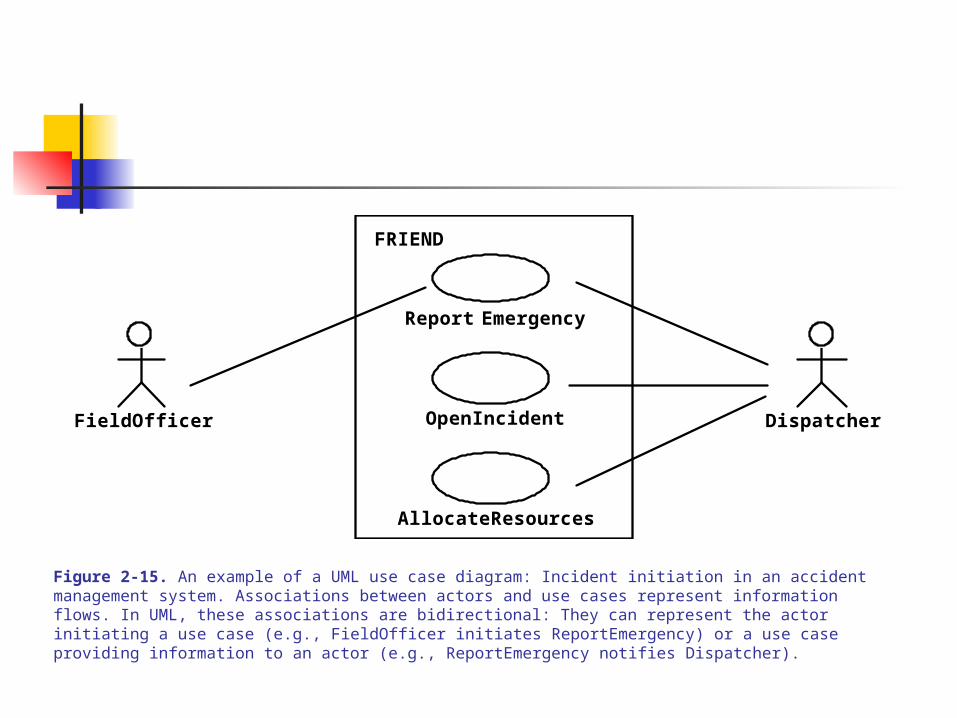
Links or bidirectional lines connecting actors and use cases represent information flow (Fig 2-15)
USE CASE TEMPLATE (natural language or textual specification – understandable to user)
A structured text of six (6) fields which describe each use case (represented in the Use Case Diagram)
Fields: name, participating actors, entry condition, flow of events (listed), exit condition, non-functional or special requirements
(Fig 2-16)
Report Emergency
FieldOfficer DispatcherOpenIncident
AllocateResources
FRIEND
Figure 2-15. An example of a UML use case diagram: Incident initiation in an accident management system. Associations between actors and use cases represent information flows. In UML, these associations are bidirectional: They can represent the actor initiating a use case (e.g., FieldOfficer initiates ReportEmergency) or a use case providing information to an actor (e.g., ReportEmergency notifies Dispatcher).
UML DIAGRAMS – IN DEPTH - 2
COMPONENTS – Scenarios: Use Case abstracts all possible scenarios in the specific functionality (containment) Scenario: An instance of a use case describing a concrete set of actions. The totality of sets of
scenarios (I.e., all use cases) completely describes the system
SCENARIO TEMPLATE (natural language or textual specification – understandable to user)
A structured text of three (3) fields which describe each scenario Fields: name (unique and underlined), participating actors (with underlined names), flow of
events (sequence of steps, with logical order) (Fig 2-17)
RELATIONSHIPS BETWEEN USE CASES (among) AND ACTORS Communication: Between actors and use cases, depicted by a solid, bidirectional line (cf. Fig 2-
15)
Include: A use case that encapsulates common functions and sharable by other use cases. A dashed arrow pointing from all the sharing use cases to the ‘common’ use case model is used to represent the relationship. [The ‘common’ use case is referenced in the ‘using’ use case template, either in the special-requirements field Or explicitly in the flow-of-event field – like ref to library units] (Fig 2-18)
Extend: Special, exception-like functions which are described in a use case model to handle pathological conditions (extension to some main functionalities) – like exception-handling routines. A dashed arrow pointing from the ‘extended’ use case model to all the using use cases is used to represent the relationship. [The ‘extended’ use case is represented in the entry field of the using use casess.] (Fig 2-19 and Fig 2-20)
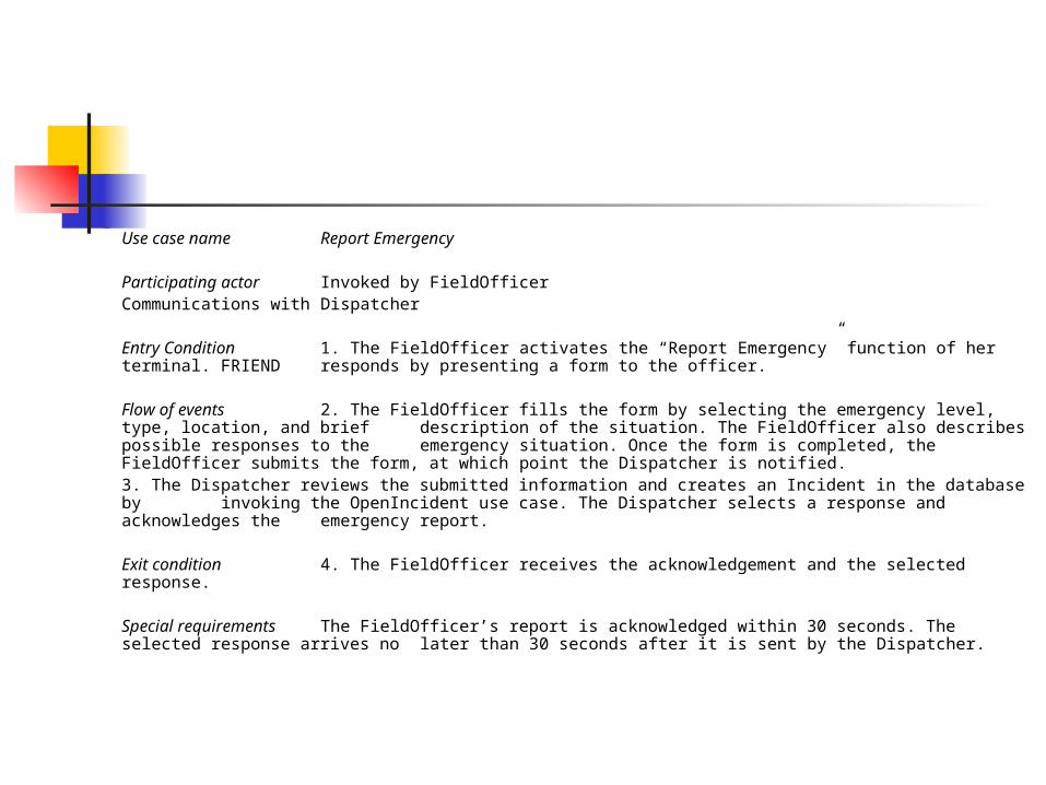
Use case name Report Emergency
Participating actor Invoked by FieldOfficerCommunications with Dispatcher
Entry Condition 1. The FieldOfficer activates the “Report Emergency” function of her terminal. FRIEND responds by presenting a form to the officer.
Flow of events 2. The FieldOfficer fills the form by selecting the emergency level, type, location, and brief description of the situation. The FieldOfficer also describes possible responses to the emergency situation. Once the form is completed, the FieldOfficer submits the form, at which point the Dispatcher is notified.
3. The Dispatcher reviews the submitted information and creates an Incident in the database by invoking the OpenIncident use case. The Dispatcher selects a response and acknowledges the emergency report.
Exit condition 4. The FieldOfficer receives the acknowledgement and the selected response.
Special requirements The FieldOfficer’s report is acknowledged within 30 seconds. The selected response arrives no later than 30 seconds after it is sent by the Dispatcher.

OpenIncident
AllocateResources
HelpDispatcher<<include>>
<<include>>
Figure 2-18. An example of an <<include>> relationship (UML use case diagram).
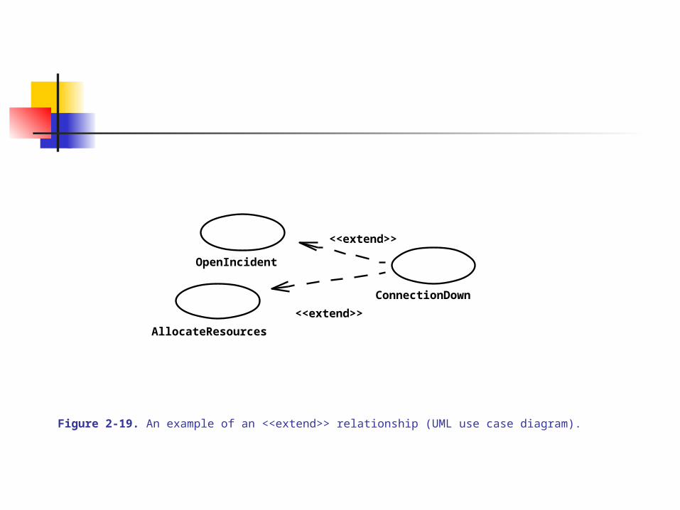
OpenIncident
AllocateResources
ConnectionDown
<<extend>>
<<extend>>
Figure 2-19. An example of an <<extend>> relationship (UML use case diagram).
UML DIAGRAMS – IN DEPTH - 3
RELATIONSHIPS BETWEEN USE CASES (among) AND ACTORS – 2
Generalization: Also called specialization relationship, is a mechanism to move details or specialization to other use cases with a high-level use case (the generalized one). A solid line with an open rectangular head from the specialized use cases to the general use case is used to represent the relationship. (Fig 2-21)
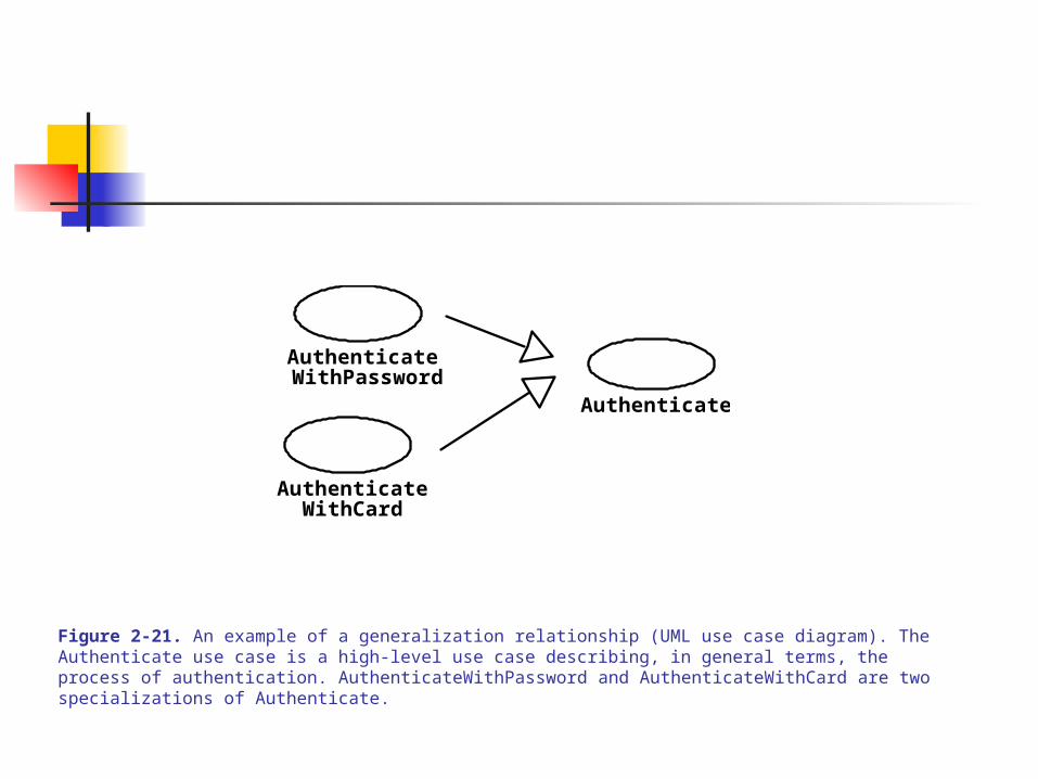
Authenticate
Authenticate
Authenticate WithPassword
WithCard
Figure 2-21. An example of a generalization relationship (UML use case diagram). The Authenticate use case is a high-level use case describing, in general terms, the process of authentication. AuthenticateWithPassword and AuthenticateWithCard are two specializations of Authenticate.
UML DIAGRAMS – IN DEPTH - 4
CLASS DIAGRAMS – Describe the structure of the system in terms of objects and classes
COMPONENTS: Classes: Abstraction or containment which describe the attributes and
behaviors of a set of objects. Class names begin with a capital letter Objects: Entities that encapsulate state and behavior, with a unique identity
or name (underlined). Object names are in lower case letters, underlined and followed by a colon and name of its class.
Each class/object diagrams has three compartments: The Top (name of class or object), The Center (displays attributes), The Bottom (displays operations). [The Center and Bottom can be omitted to reduce clutter.]
The attributes could be typed (preceded by the attribute name and a colon) in the Class Diagram
The attributes could be assigned values (preceded by the attribute name and the assignment op) in Object Diagrams
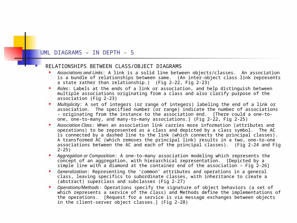
UML DIAGRAMS – IN DEPTH - 5
RELATIONSHIPS BETWEEN CLASS/OBJECT DIAGRAMS Associations and Links: A link is a solid line between objects/classes. An association is a
bundle of relationships between same. (An inter-object class link represents a state rather than relationship.) (Fig 2-22, Fig 2-23)
Roles: Labels at the ends of a link or association, and help distinguish between multiple associations originating from a class and also clarify purpose of the association (Fig 2-23)
Multiplicity: A set of integers (or range of integers) labeling the end of a link or association. The specified number (or range) indicate the number of associations – originating from the instance to the association end. [There could a one-to-one, one-to-many, and many-to-many associations.] (Fig 2-22, Fig 2-25)
Association Class: When an association link carries more information (attributes and operations) to be represented as a class and depicted by a class symbol. The AC is connected by a dashed line to the link (which connects the principal classes). A transformed AC (which removes the principal link) results in a two, one-to-one associations between the AC and each of the principal classes). (Fig 2-24 and Fig 2-25)
Aggregation or Composition: A one-to-many association modeling which represents the concept of an aggregation, with hierarchical representation. [Depicted by a simple line with a diamond at the container end of the association – Fig 2-26]
Generalization: Representing the ‘common’ attributes and operations in a general class, leaving specifics to subordinate classes, with inheritance to create a (abstract) superclass and subclasses (Fig 2-27)
Operations/Methods: Operations specify the signature of object behaviors (a set of which represents a service of the class) and Methods define the implementations of the operations. [Request for a service is via message exchanges between objects in the client-server object classes.] (Fig 2-28)
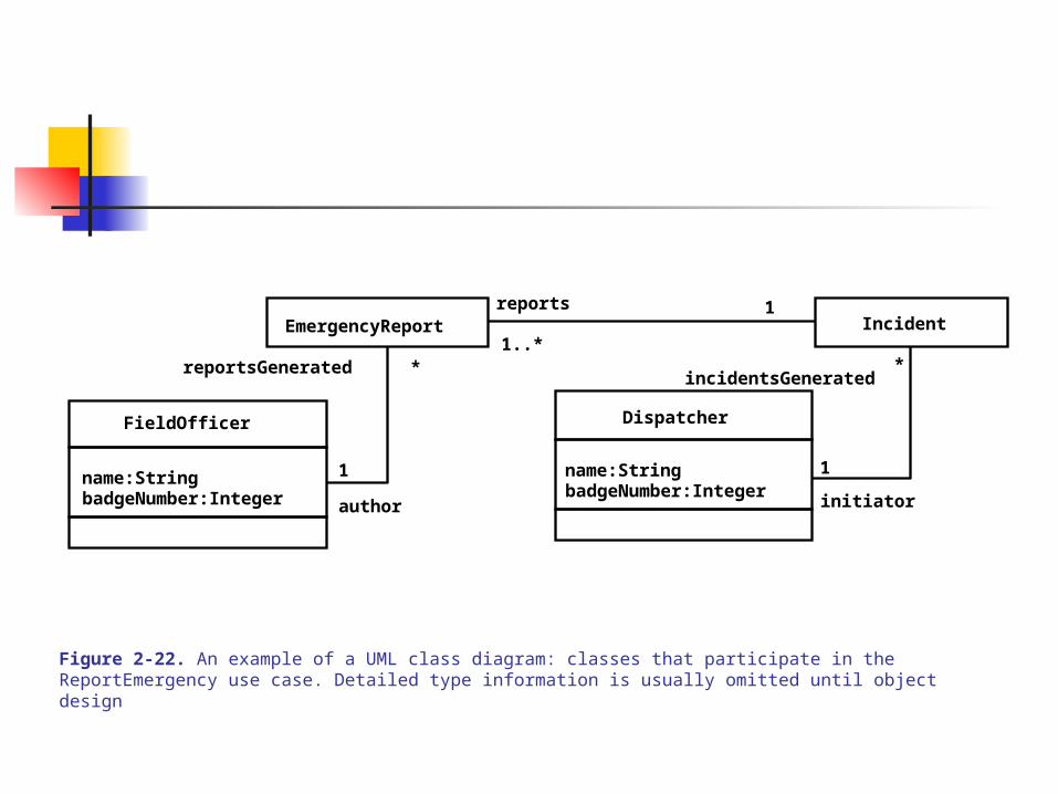
EmergencyReport Incident
FieldOfficer
name:StringbadgeNumber:Integer
Dispatcher
name:StringbadgeNumber:Integer
author
incidentsGeneratedreportsGenerated
initiator
reports
1
*
1
*1..*
1
Figure 2-22. An example of a UML class diagram: classes that participate in the ReportEmergency use case. Detailed type information is usually omitted until object design
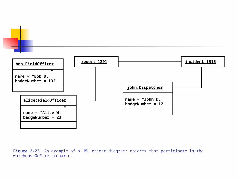
report_1291 incident_1515bob:FieldOfficer
name = “Bob D.”badgeNumber = 132
john:Dispatcher
name = “John D.”badgeNumber = 12
alice:FieldOfficer
name = “Alice W.”badgeNumber = 23
Figure 2-23. An example of a UML object diagram: objects that participate in the warehouseOnFire scenario.
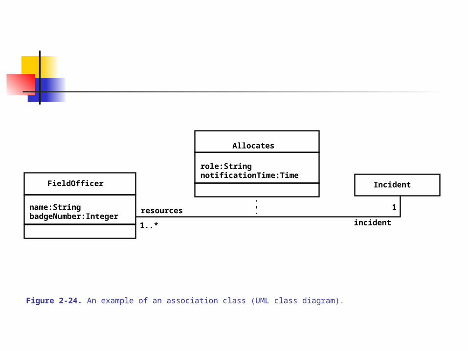
IncidentFieldOfficer
name:StringbadgeNumber:Integer
Allocates
role:StringnotificationTime:Time
resources
incident
1
1..*
Figure 2-24. An example of an association class (UML class diagram).

Incident
FieldOfficer
name:StringbadgeNumber:Integer
Allocation
role:StringnotificationTime:Time
resources
incident 1
1..*
11
Figure 2-25. Alternative model for Allocation (UML class diagram).
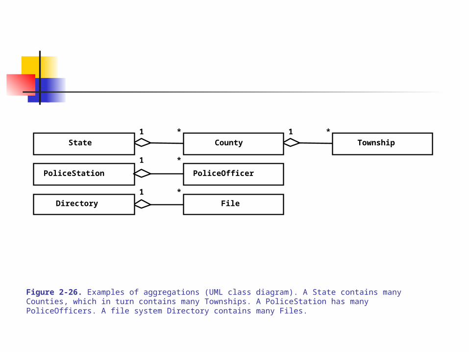
* *
PoliceStation
*
*
1
1
1
1State
Directory
County
PoliceOfficer
File
Township
Figure 2-26. Examples of aggregations (UML class diagram). A State contains many Counties, which in turn contains many Townships. A PoliceStation has many PoliceOfficers. A file system Directory contains many Files.
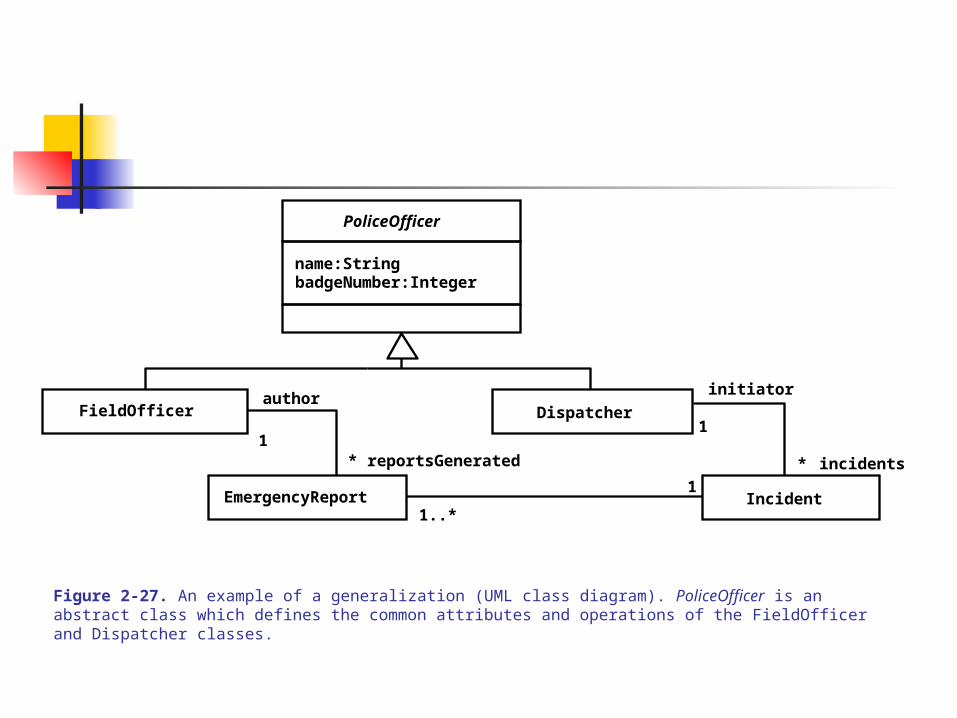
EmergencyReport Incident
FieldOfficer Dispatcherauthor
initiator
reportsGenerated incidents
1
*
1*
1..*
1
PoliceOfficer
name:StringbadgeNumber:Integer
Figure 2-27. An example of a generalization (UML class diagram). PoliceOfficer is an abstract class which defines the common attributes and operations of the FieldOfficer and Dispatcher classes.
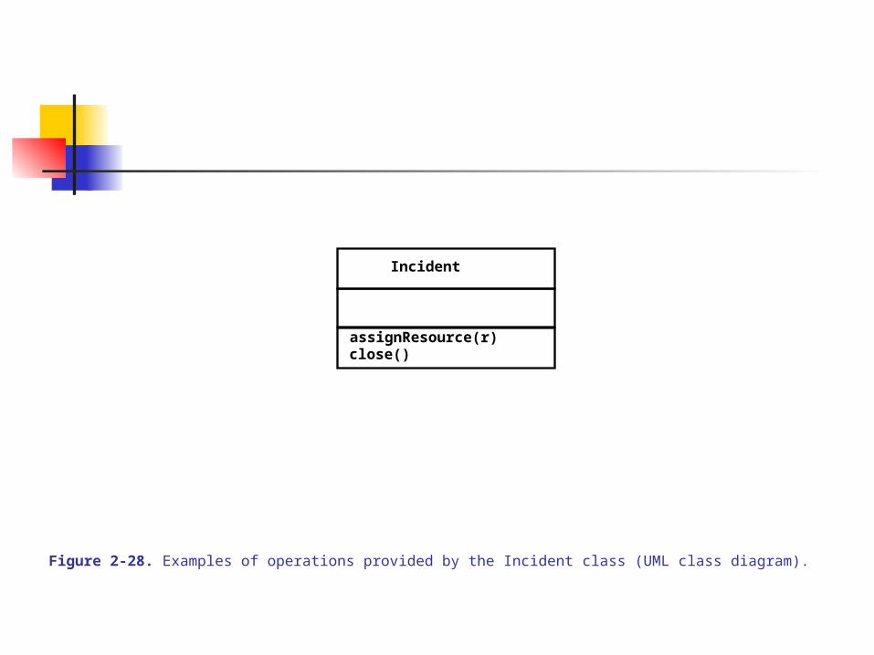
Incident
assignResource(r)close()
Figure 2-28. Examples of operations provided by the Incident class (UML class diagram).
UML DIAGRAMS – IN DEPTH - 6
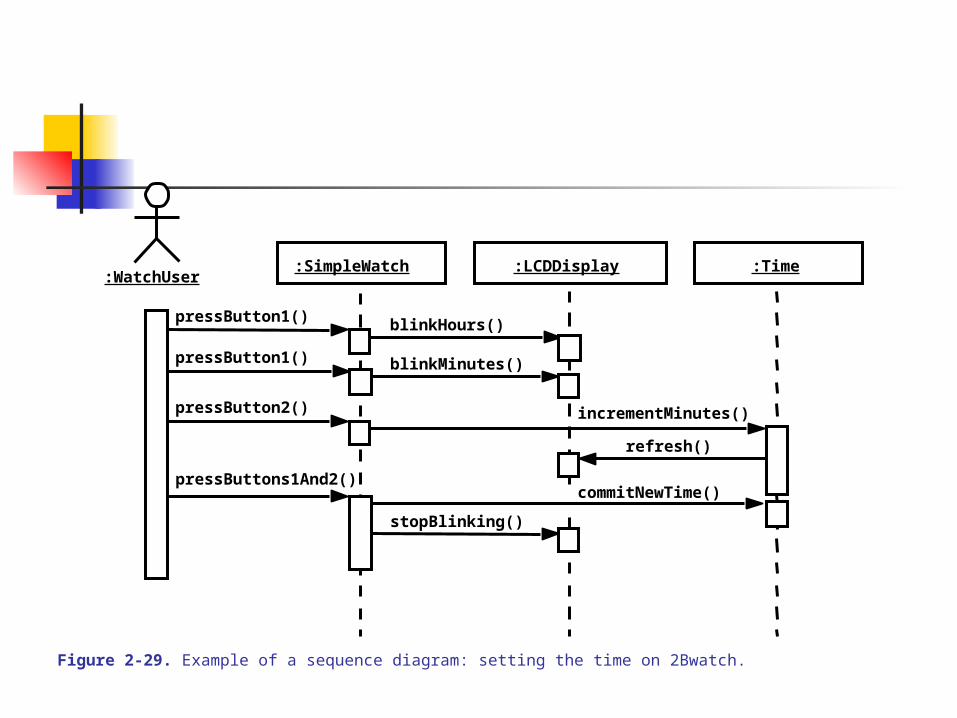
SEQUENCE DIAGRAMS – Describe patterns of communication among a set of interacting objects via message exchanges. Optionally parameterized message reception generates an event occurrence and execution of an operation / service. (Fig 2-29)
SD are typically used to describe event flow of a use case, identify participating objects in the use case, and describe the necessary use case behavior of these objects to form a particular service.
COMPONENTS: Columns: represents a participating object in the interaction Vertical Axis: represents time passage (from top to down), and time-intervals or elapsed
can be labeled Arrowed line: indicate messages Labels of arrows: represent message names (with optional arguments) Vertical rectangles: Depict message activation Leftmost column: Represent actors (could also be rightmost column) [Participating
objects are typically called control and boundary objects.]
Other Semantics When describing all possible interactions, SD can bear conditional and iterative
expressions. (Fig 2-30)
blinkHours()
blinkMinutes()
incrementMinutes()
refresh()
commitNewTime()
stopBlinking()
pressButton1()
pressButton2()
pressButtons1And2()
pressButton1()
:WatchUser:Time:LCDDisplay:SimpleWatch
Figure 2-29. Example of a sequence diagram: setting the time on 2Bwatch.

a b c
[i>0] op1()
[i<=0] op2()
*op3()
Figure 2-30. Examples of conditions and iterators in sequence diagrams.

UML DIAGRAMS – IN DEPTH - 7
STATECHART DIAGRAMS – Statecharts make explicit the attribute, or set of attributes, which impact on the behavior of a single object using a sequence of states an object goes through in response to external events. Statecharts extend finite state machines.
The provide a notation for nesting states and FSM, a notation for transitions (with messages and conditions) between states.
COMPONENTS:
A State: A condition that an object satisfies (an abstraction of a set of valued attributes in a class) (Fig 2-31). Depicted by a rounded rectangle.
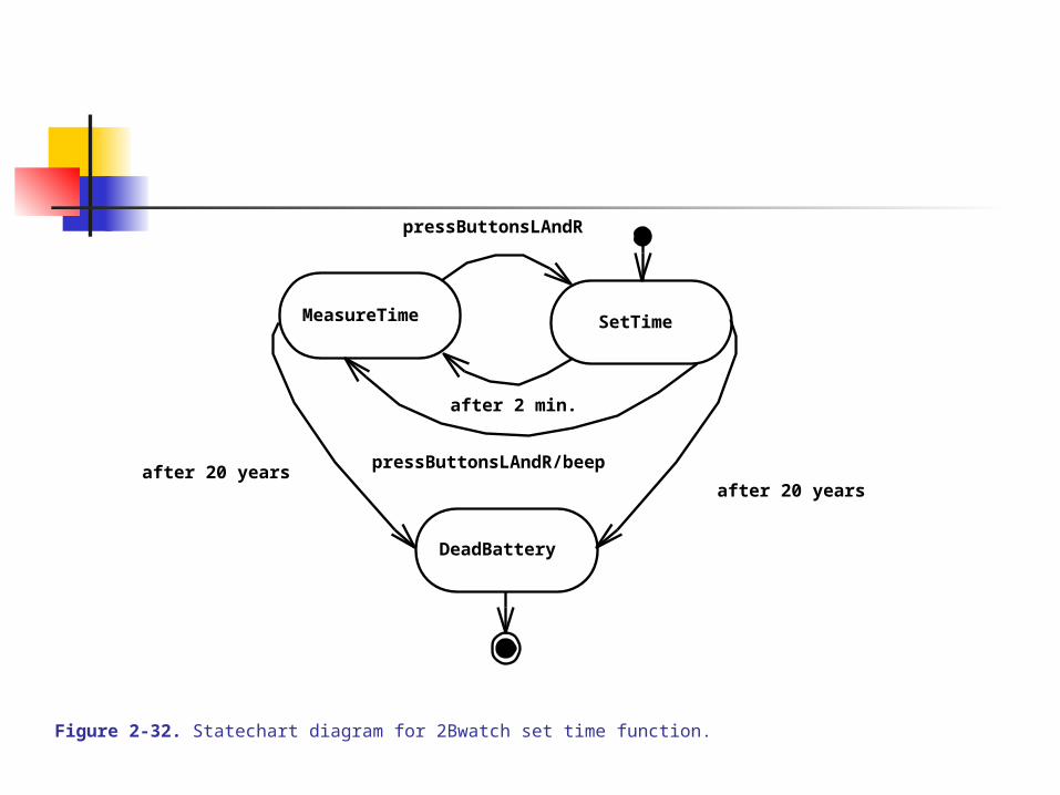
A Transition: Changes of state triggered by events, conditions, or time. Depicted by an arrow
Start/End States: Special states that indicate the initial and final states, and respectively indicated by a solid black circle and a circled solid black circle
(See Fig 2-32 – A statechart of the 2BWatch)
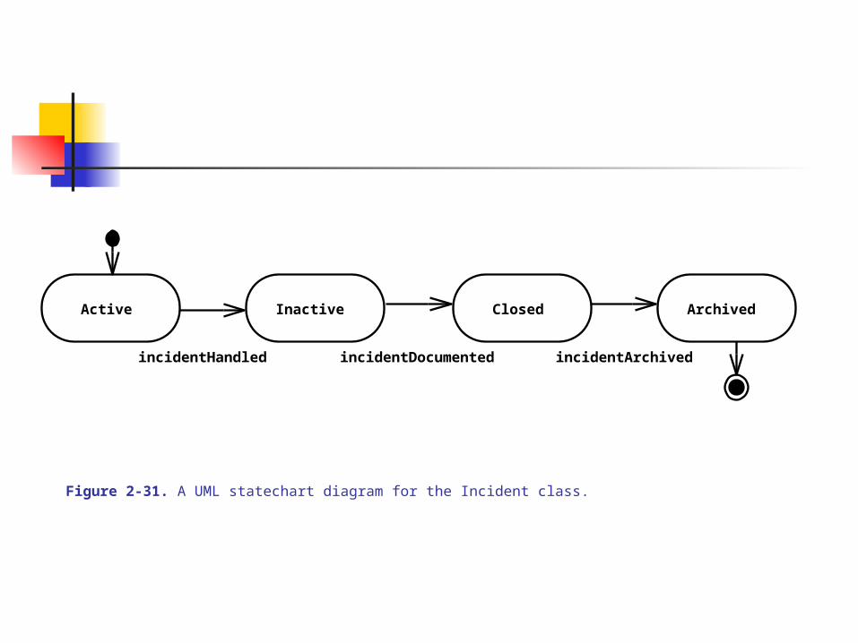
Active Inactive Closed Archived
incidentHandled incidentDocumented incidentArchived
Figure 2-31. A UML statechart diagram for the Incident class.
MeasureTime SetTime
pressButtonsLAndR
pressButtonsLAndR/beep
after 2 min.
DeadBattery
after 20 yearsafter 20 years
Figure 2-32. Statechart diagram for 2Bwatch set time function.

UML DIAGRAMS – IN DEPTH - 8
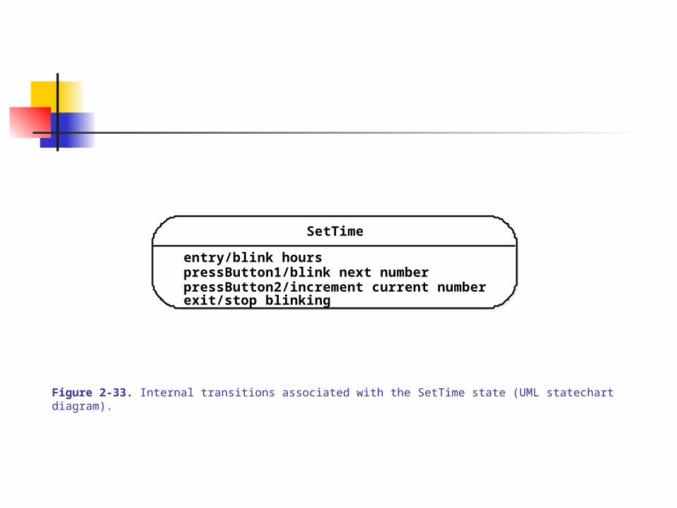
STATECHART DIAGRAMS – 1 Internal Transition or nested statecharts
Detail the event-flows within each single state: syntactically – action/state-change, with labeled transitions. Entry/exit states are also indicated.
Internal transitions can also be used to detail nested statecharts Statecharts and internal transitions are used to identify object attributes
and refine behavior description Statecharts are used at the System Analysis and Object Design states to
describe object dynamic models in the solution domain
(See Fig 2-33 and Fig 2-34)
SetTime
entry/blink hours
exit/stop blinking
pressButton1/blink next numberpressButton2/increment current number
Figure 2-33. Internal transitions associated with the SetTime state (UML statechart diagram).

SetTime
BlinkHours BlinkMinutes BlinkSeconds
BlinkYear BlinkMonth BlinkDay
b2/incr hour b2/incr min. b2/incr sec.
b2/incr year b2/incr mo. b2/incr day
b1
b1
b1
b1
b1b1
Figure 2-34. Refined statechart associated with the SetTime state (UML statechart diagram).
UML DIAGRAMS – IN DEPTH - 9
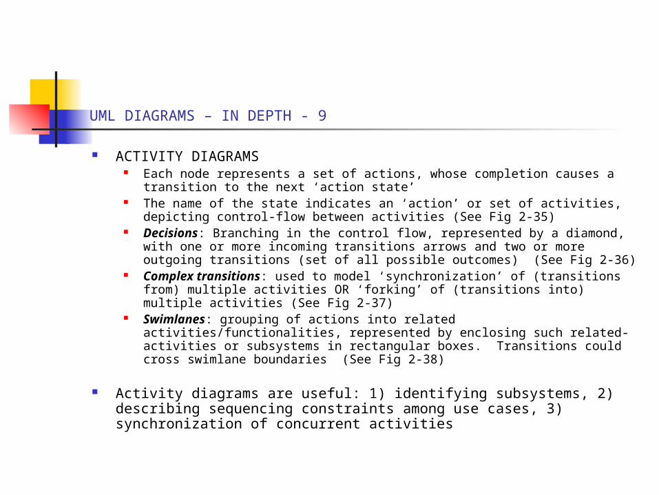
ACTIVITY DIAGRAMS Each node represents a set of actions, whose completion causes a
transition to the next ‘action state’ The name of the state indicates an ‘action’ or set of activities, depicting
control-flow between activities (See Fig 2-35) Decisions: Branching in the control flow, represented by a diamond, with
one or more incoming transitions arrows and two or more outgoing transitions (set of all possible outcomes) (See Fig 2-36)
Complex transitions: used to model ‘synchronization’ of (transitions from) multiple activities OR ‘forking’ of (transitions into) multiple activities (See Fig 2-37)
Swimlanes: grouping of actions into related activities/functionalities, represented by enclosing such related-activities or subsystems in rectangular boxes. Transitions could cross swimlane boundaries (See Fig 2-38)
Activity diagrams are useful: 1) identifying subsystems, 2) describing sequencing constraints among use cases, 3) synchronization of concurrent activities
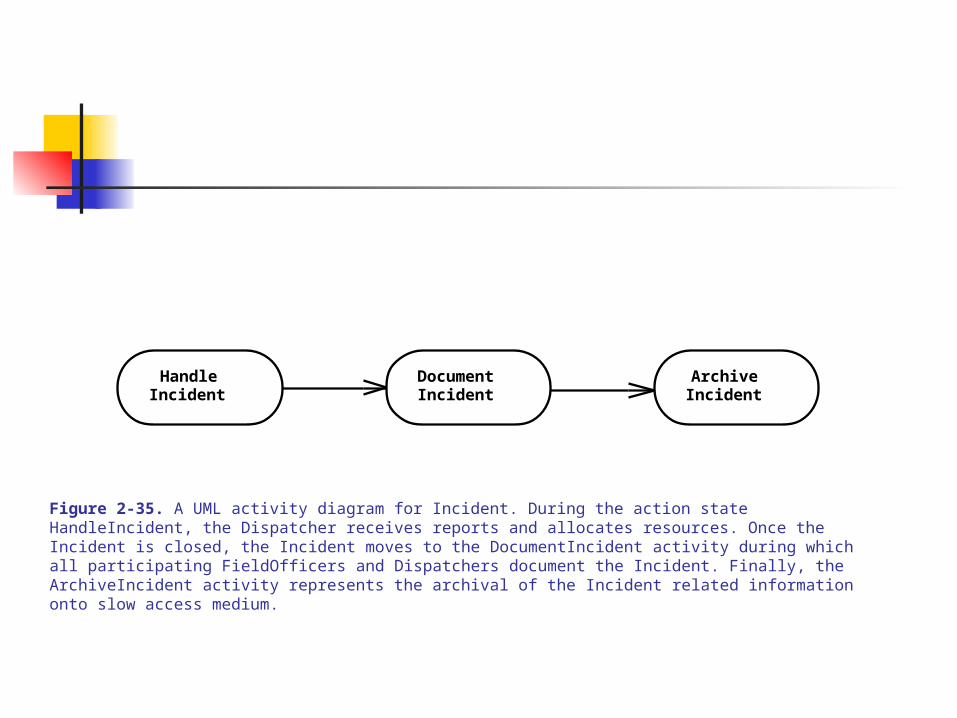
DocumentIncident
ArchiveIncident
HandleIncident
Figure 2-35. A UML activity diagram for Incident. During the action state HandleIncident, the Dispatcher receives reports and allocates resources. Once the Incident is closed, the Incident moves to the DocumentIncident activity during which all participating FieldOfficers and Dispatchers document the Incident. Finally, the ArchiveIncident activity represents the archival of the Incident related information onto slow access medium.
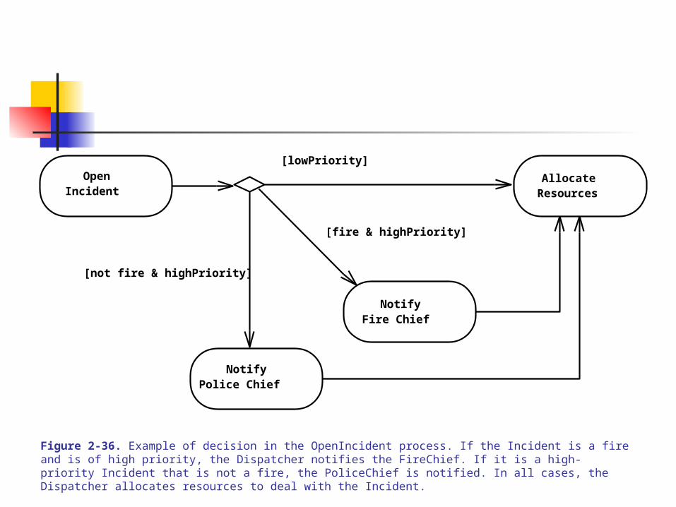
[fire & highPriority]
[not fire & highPriority]
[lowPriority]
NotifyFire Chief
OpenIncident
NotifyPolice Chief
AllocateResources
Figure 2-36. Example of decision in the OpenIncident process. If the Incident is a fire and is of high priority, the Dispatcher notifies the FireChief. If it is a high-priority Incident that is not a fire, the PoliceChief is notified. In all cases, the Dispatcher allocates resources to deal with the Incident.
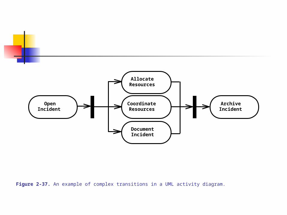
ArchiveIncident
OpenIncident
DocumentIncident
AllocateResources
CoordinateResources
Figure 2-37. An example of complex transitions in a UML activity diagram.
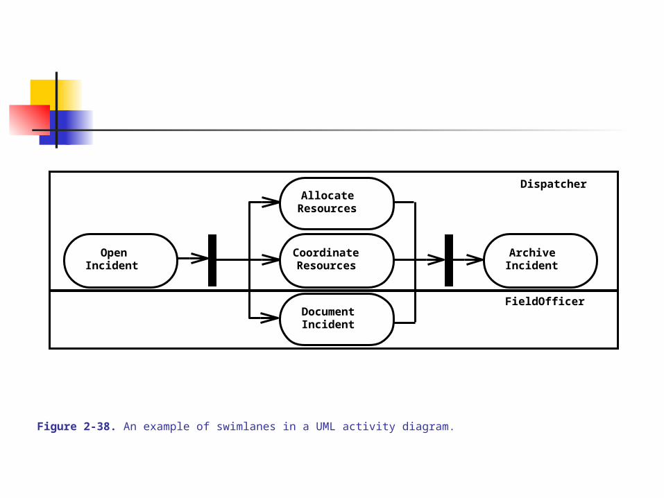
ArchiveIncident
Dispatcher
FieldOfficer
OpenIncident
DocumentIncident
AllocateResources
CoordinateResources
Figure 2-38. An example of swimlanes in a UML activity diagram.

UML DIAGRAMS – IN DEPTH - 10
Diagram Organization using Packages Dealing with complex models, group related ‘elements’ into packages
(where an elements are use cases, classes, activities Grouping could be by actors, functions-activities, etc. The details of elements within a package could be abstracted (suppressed)
Example of use-case grouping into packages – (See Fig 2-39 an Fig 2-40)
Example of class-diagram grouping into packages – (See Fig 2-41 – based on incident site where objects are created)
Packages are just for organizing the basic UML diagramming elements. Packages that have any syntactic or semantic behaviors
Packages can be annotated with ‘notes’ for comments, remarks, to-do’s, reminders, etc. (See Fig 4-42)
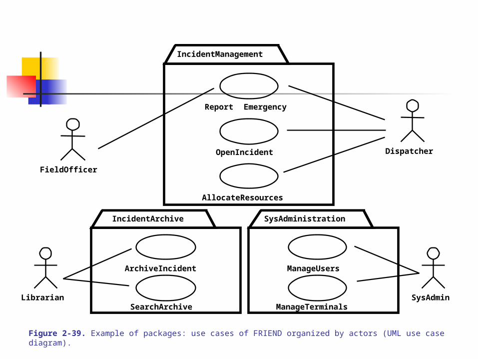
Report Emergency
FieldOfficer
DispatcherOpenIncident
AllocateResources
ArchiveIncident
SearchArchive
ManageUsers
ManageTerminalsLibrarian SysAdmin
SysAdministrationIncidentArchive
IncidentManagement
Figure 2-39. Example of packages: use cases of FRIEND organized by actors (UML use case diagram).
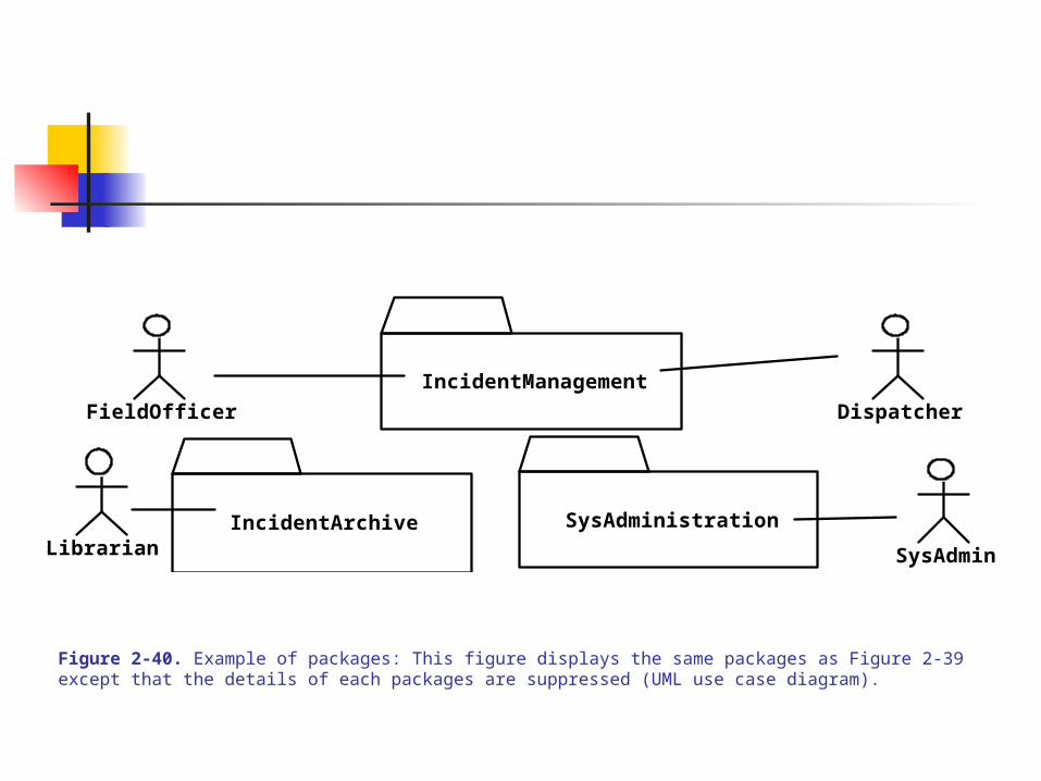
FieldOfficer Dispatcher
Librarian SysAdmin
IncidentArchive SysAdministration
IncidentManagement
Figure 2-40. Example of packages: This figure displays the same packages as Figure 2-39 except that the details of each packages are suppressed (UML use case diagram).
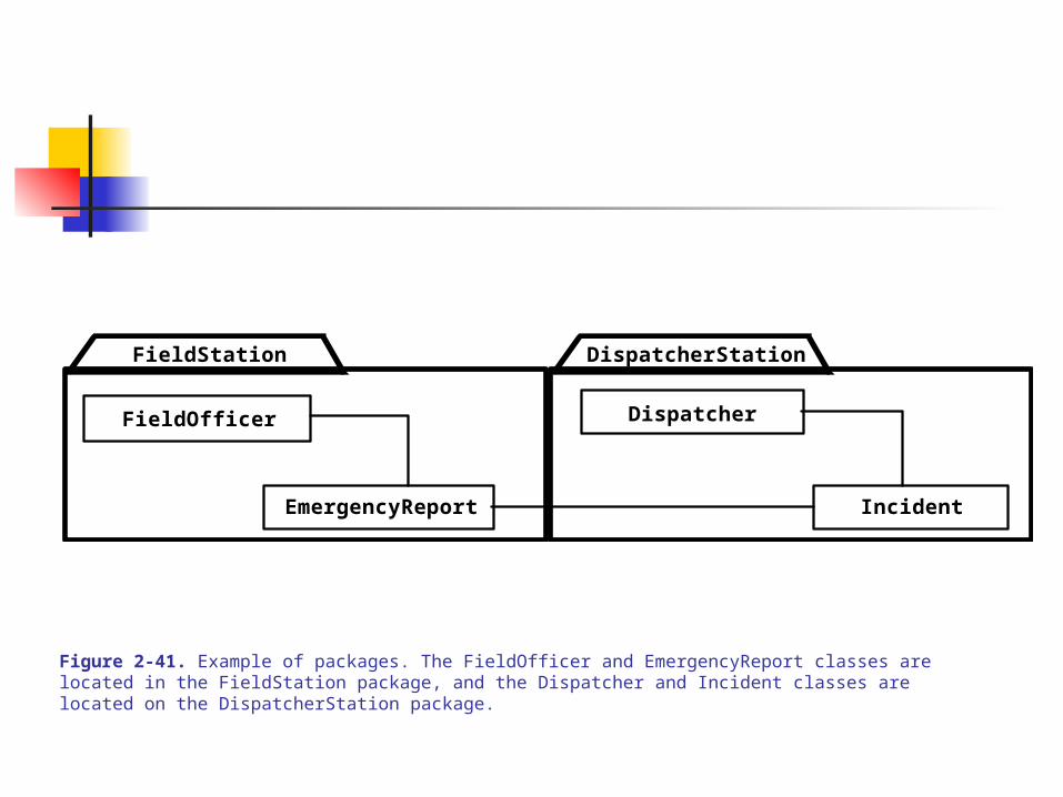
DispatcherStation
EmergencyReport Incident
FieldOfficer Dispatcher
FieldStation
Figure 2-41. Example of packages. The FieldOfficer and EmergencyReport classes are located in the FieldStation package, and the Dispatcher and Incident classes are located on the DispatcherStation package.
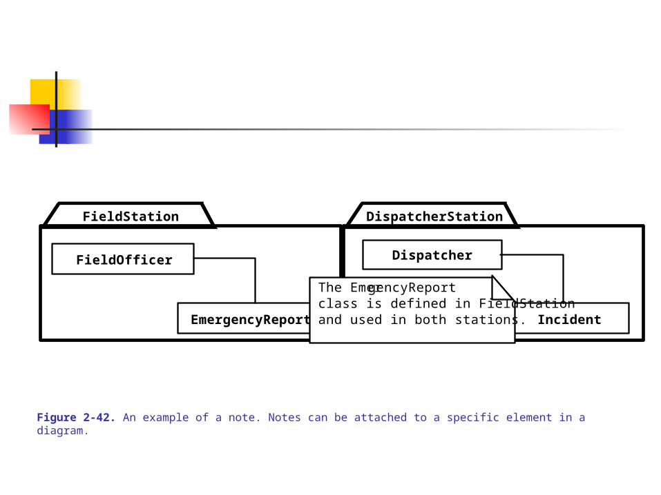
EmergencyReport
DispatcherStation
Incident
FieldOfficer Dispatcher
FieldStation
The EmergencyReportclass is defined in FieldStationand used in both stations.
Figure 2-42. An example of a note. Notes can be attached to a specific element in a diagram.
UML DIAGRAMS – IN DEPTH - 11
Diagram Extensions UML provides a set of basic diagramming notations for modeling complex
systems UML provides a number of extension mechanisms to extend the languages UML extensions are called: stereotypes and constraints
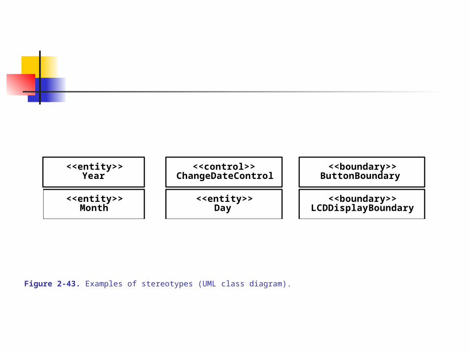
Stereotypes: - a string enclosed in a pair of angle brackets, <<string>>, which is attached to an UML element (a class or an association)
Allows creation of new building blocks for the given application domain or problem area
E.g., the introduction of specific object type - <<control>>, <<boundary>>, <<entity>>
(See Fig 2-43)
Constraint - rule that is attached to an UML building block E.g., attaching a rule that requires ‘sorting of documents/reports’ in
chronological order via the association (See Fig 2-44) Constraints may be expressed using an informal string or using a
formal language like OCL (Object Constraint Language – subset of UML), when enclosed in a pair of square brackets [].
<<entity>>
<<entity>>
<<boundary>>
<<boundary>>
<<control>>Year
Month
ChangeDateControl
LCDDisplayBoundary
ButtonBoundary
<<entity>>Day
Figure 2-43. Examples of stereotypes (UML class diagram).

EmergencyReport Incidentreports1..*
1
{ordered by time of receipt}
Figure 2-44. An example of constraint (UML class diagram).


![Specification of Graphical Notation€¦ · Since the M2 model is defined with UML [14] and UML is a standard within the soft-ware industry, the idea of using UML for M1 modeling](https://static.fdocuments.in/doc/165x107/5f5cb2bedde77949823df17e/specification-of-graphical-notation-since-the-m2-model-is-defined-with-uml-14.jpg)