Modeling Real-Time Applications in RSARTE...Real-time applications have special characteristics...
46
Modeling Real-Time Applications in RSARTE Mattias Mohlin Senior Software Architect IBM INTRODUCTION...................................................................................................................................................3 THE RT SUBSET OF UML...................................................................................................................................4 CAPSULE................................................................................................................................................................. 4 PASSIVE CLASS.........................................................................................................................................................6 PROTOCOL...............................................................................................................................................................6 RT Service Protocols.......................................................................................................................................7 Protocol State Machines and Interactions......................................................................................................9 PACKAGE...............................................................................................................................................................10 COMPONENT...........................................................................................................................................................11 ENUMERATION........................................................................................................................................................12 INTERFACE............................................................................................................................................................. 12 GENERALIZATION.................................................................................................................................................... 13 Generalization of Protocols.......................................................................................................................... 14 Promotion and Demotion..............................................................................................................................15 Excluding Inherited Elements....................................................................................................................... 15 Inheritance Rearrangement...........................................................................................................................16 DEPENDENCY..........................................................................................................................................................16 ASSOCIATION..........................................................................................................................................................17 ATTRIBUTE............................................................................................................................................................ 18 Multiplicity.................................................................................................................................................... 19 PORT.....................................................................................................................................................................21 Dynamic Connections for Non-Wired Ports................................................................................................. 23 COMPOSITE STRUCTURE........................................................................................................................................... 24 OPERATION............................................................................................................................................................26 Constructor and Destructor.......................................................................................................................... 27 Thrown Exceptions........................................................................................................................................27 EVENT...................................................................................................................................................................27 Priorities........................................................................................................................................................28 The rtBound and rtUnbound Events..............................................................................................................29 STATE MACHINE.....................................................................................................................................................29 Hierarchical State Machine.......................................................................................................................... 34 Deferring and Recalling Messages............................................................................................................... 39 State Machine in Passive Class.....................................................................................................................40 ARTIFACT.............................................................................................................................................................. 42 TRANSFORMATION CONSTRAINTS............................................................................................................43 NAMES..................................................................................................................................................................43 THE UML-RT PROFILE AND LIBRARIES....................................................................................................44 CPPPRIMITIVEDATATYPES........................................................................................................................................44 RTCLASSES...........................................................................................................................................................45 RTCOMPONENTS....................................................................................................................................................45
Transcript of Modeling Real-Time Applications in RSARTE...Real-time applications have special characteristics...
Modeling Real-Time Applications in RSARTE
Mattias MohlinSenior Software Architect
IBM
INTRODUCTION...................................................................................................................................................3
THE RT SUBSET OF UML...................................................................................................................................4
CAPSULE.................................................................................................................................................................4PASSIVE CLASS.........................................................................................................................................................6PROTOCOL...............................................................................................................................................................6
RT Service Protocols.......................................................................................................................................7Protocol State Machines and Interactions......................................................................................................9
PACKAGE...............................................................................................................................................................10COMPONENT...........................................................................................................................................................11ENUMERATION........................................................................................................................................................12INTERFACE.............................................................................................................................................................12GENERALIZATION....................................................................................................................................................13
Generalization of Protocols..........................................................................................................................14Promotion and Demotion..............................................................................................................................15Excluding Inherited Elements.......................................................................................................................15Inheritance Rearrangement...........................................................................................................................16
DEPENDENCY..........................................................................................................................................................16ASSOCIATION..........................................................................................................................................................17ATTRIBUTE............................................................................................................................................................18
Multiplicity....................................................................................................................................................19PORT.....................................................................................................................................................................21
Dynamic Connections for Non-Wired Ports.................................................................................................23COMPOSITE STRUCTURE...........................................................................................................................................24OPERATION............................................................................................................................................................26
Constructor and Destructor..........................................................................................................................27Thrown Exceptions........................................................................................................................................27
EVENT...................................................................................................................................................................27Priorities........................................................................................................................................................28The rtBound and rtUnbound Events..............................................................................................................29
STATE MACHINE.....................................................................................................................................................29Hierarchical State Machine..........................................................................................................................34Deferring and Recalling Messages...............................................................................................................39State Machine in Passive Class.....................................................................................................................40
ARTIFACT..............................................................................................................................................................42
TRANSFORMATION CONSTRAINTS............................................................................................................43
NAMES..................................................................................................................................................................43
THE UML-RT PROFILE AND LIBRARIES....................................................................................................44
CPPPRIMITIVEDATATYPES........................................................................................................................................44RTCLASSES...........................................................................................................................................................45RTCOMPONENTS....................................................................................................................................................45

This document describes the concepts involved when designing real-time applications usingRational Software Architect Real Time Edition (RSARTE). This includes the subset of the Unified Modeling Language (UML) that is used when modeling these kinds of applications. Italso includes some additional concepts that are introduced by means of a UML RealTime pro-file known as UML-RT, which further constrains and formalizes the structure and behavior ofthese kinds of models. Finally it includes concepts present in a run-time library called the RT services library, some of which are available for use in the model.
Readers of this document are assumed to have a basic understanding of UML 2 and real-time applications. The document was last updated for RSARTE 10.2. All screen shots were cap-tured on the Windows platform.

IntroductionReal-time applications have special characteristics compared to other kinds of applications. For example, real-time applications are often complex, event-driven, stateful, resource effi-cient and distributed. The purpose of RSARTE is to facilitate the modeling and development of real-time applications. This is accomplished by
1. Defining a smaller subset of the otherwise very large UML. This subset is known as "the RT subset of UML".
2. Introducing new real-time specific concepts by means of a profile (called UML-RT).3. Supporting an automated transformation of models that conform to the above con-
straints to yield efficient target code, such as C++.4. Providing a run-time library (known as the RT services library) which together with
generated and hand-written code can be compiled into an executable real-time applica-tion.
From a tool's point of view RSARTE is an extension on top of Eclipse. It is normally installedon the Eclipse for C/C++ Development distribution which means that it contains a full-fledged C/C++ development environment (CDT). However, it can also be used as a more gen-eral modeling tool, and in fact it supports the full UML 2 standard. This means that RSARTE may appear somewhat overwhelming for someone who only wants to use the smaller RT sub-set for designing an application. This document is intended to help out by describing the RT subset of UML, as well as the UML-RT profile and libraries. This document is intended to cover all concepts which a designer has to be familiar with to be able to create models for real-time applications using RSARTE.
It should be mentioned that other parts of the UML also may be useful for modeling a real-time application. For example, during analysis phases and for systems modeling, many other language constructs from UML are useful, such as the ones shown in use case and sequence diagrams. This document does not cover these language constructs and is therefore mainly in-tended for users who use RSARTE for designing and developing RT models that are trans-formed into real-time application code.
3
The RT Subset of UMLA real-time application model in RSARTE is constructed by using a relatively small number of concepts:
Type conceptso Capsuleso Passive classeso Protocolso Enumerationso Interfaces
Grouping conceptso Packageso Components
Relationship conceptso Generalizationso Dependencieso Associations
Structural conceptso Attributeso Portso Connectors
Behavioral conceptso Operationso Eventso State machines
In addition, an RT model contains action code, typically C++. Such code appears in the modelat various places where action code is allowed, for example as the body of operations, the ef-fect of transitions and entry/exit behaviors of states. But action code is also used for expres-sions, such as transition guards and attribute default values. Furthermore, the types that are available in the action code are also frequently used in the model, both primitive types (int, bool etc.) and external data types (e.g. hand-written C++ classes).Where action code is used in examples of this document we will use C++. However, it should be mentioned that RSARTE also supports C code.
The rest of this chapter goes through the above mentioned concepts in more detail.
CapsuleCapsules are the fundamental building blocks of a real-time model. They represent units within the modeled system which encapsulate data and structure as well as behavior. A cap-sule is an active UML object which means that it has its own independent flow of control.In the RT model a capsule is a class stereotyped by a «Capsule» stereotype.
4

Just like a regular UML class a capsule can have attributes and operations. However, capsuleshave some constraints compared to regular classes, which make them suited for real-time ap-plications. The most important constraint is that references to capsule instances should not be passed around in the application, like regular class instance references. All references to cap-sule instances are strictly managed by the underlying run-time system, which avoids concur-rency problems which otherwise may arise in real-time applications. In practice this constraintimplies the following:
A capsule instance is always created by a service in the run-time library, never by di-rect use of the 'new' operator. The process of instantiating a capsule is called incarna-tion, and a capsule instance is said to be an incarnation of a capsule.A capsule instance is usually stored in a part attribute of another capsule. Such part at-tributes are called capsule parts.
Although a capsule can have public operations and attributes, it is not recommended toaccess these from outside the capsule, since this would require holding a reference to acapsule instance1. However, static operations and attributes can be accessed without having a capsule instance.
The normal means to communicate with a capsule instance is by sending messages to it. However, messages cannot be directly sent to a capsule instance since that also would require holding a reference to it. Instead, messages are sent through certain ports (known as service ports), and get routed through connectors and relay ports until a receiver capsule instance is reached. This means that public service ports is the main external interface of a capsule.
A capsule may contain a composite structure, defined using a composite structure diagram. The composite structure defines which capsule parts that are contained in a capsule. It may also define how the ports of a capsule are connected to other ports on these capsule parts by means of connectors. Such a connector structure defines the routing of messages that arrive at the capsule's service ports. See Composite Structure for more information about this.
A capsule may also contain behavior in the form of a state machine, defined using a state ma-chine diagram. Action code in this state machine can access attributes and operations defined on the capsule. See State Machine for more information about the state machine of a capsule.
As said above a capsule has its own independent flow of control. To be precise, each capsule instance that has a state machine has its own flow of control, called a logical thread of con-trol. It is possible to let the same processing thread (known as a physical thread) drive multi-ple logical threads, but this is completely transparent and does not affect the design of the cap-1It is indeed safe to access public operations and attributes in those cases where the calling code is guaranteed to execute in the same physical thread as the capsule.
5
sule in any way. In fact, one of the benefits with designing real-time applications usingRSARTE is that it is easy to change the mapping of logical threads onto physical threads without affecting the design of the model.
It should be noted that since action code like C++ is used, it is of course possible to write codethat will get hold of a capsule instance and send this reference around in the application. How-ever, if you do this you must be very careful. Making such a reference accessible for code thatruns in a different logical thread may lead to run-time problems and is not recommended.
Passive ClassNot all objects in a real-time application need their own logical thread. Many objects are sim-ply passive data objects that always run in the context of another logical thread. To model such objects regular UML classes are used. To distinguish them from capsules, which also areclasses, the term passive class or data class is often used.
Passive classes have none of the constraints that are put on capsules. However, this also means that you have to be careful to avoid accessing the same passive class instance simulta-neously from different logical threads, as this could lead to concurrency problems if these log-ical threads are mapped onto different physical threads.
Except from regular operations, implemented in C++, it is possible to define the behavior of a passive class using a state machine. See State Machine in Passive Class for more information about passive class state machines.
It is usually good practice to let the instances of passive classes be managed by the capsule in the logical thread of which they will be run. Giving a reference to the capsule to a passive class instance is not a problem if this recommendation is followed, since all code accessing that reference then will run within the same logical thread. With a reference to the managing capsule a passive class instance can invoke operations on the capsule, which can be useful in order to, for example, send events through the ports of the capsule.
If you want to pass a reference to a capsule instance to a passive class, it's recommended to letthe capsule implement an interface which exposes only the operations that the passive class needs to call. Thereby you can define more clearly what functionality the capsule exposes to its passive classes, and you avoid to accidentally use other parts of the capsule implementa-tion.
ProtocolA protocol defines what kinds of messages that may be sent in to and out from a port. Incom-ing messages are described by in-events and outgoing messages are described by out-events. Hence, a protocol is a kind of communication contract between users of a port. A protocol is used as the type of all ports which share the same contract.
In the RT model a protocol is a UML collaboration stereotyped by a «Protocol» stereotype.
In a class diagram protocols can be visualized using class-like symbols as shown in the exam-ple below:
6
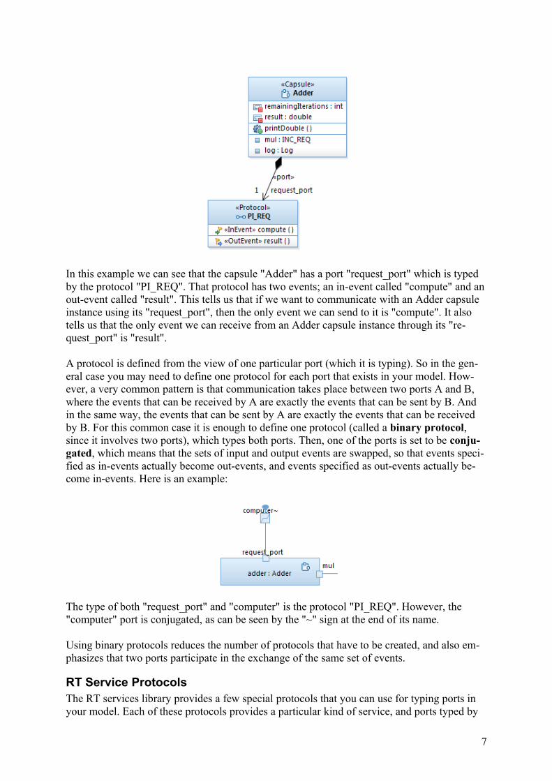
In this example we can see that the capsule "Adder" has a port "request_port" which is typed by the protocol "PI_REQ". That protocol has two events; an in-event called "compute" and anout-event called "result". This tells us that if we want to communicate with an Adder capsule instance using its "request_port", then the only event we can send to it is "compute". It also tells us that the only event we can receive from an Adder capsule instance through its "re-quest_port" is "result".
A protocol is defined from the view of one particular port (which it is typing). So in the gen-eral case you may need to define one protocol for each port that exists in your model. How-ever, a very common pattern is that communication takes place between two ports A and B, where the events that can be received by A are exactly the events that can be sent by B. And in the same way, the events that can be sent by A are exactly the events that can be received by B. For this common case it is enough to define one protocol (called a binary protocol, since it involves two ports), which types both ports. Then, one of the ports is set to be conju-gated, which means that the sets of input and output events are swapped, so that events speci-fied as in-events actually become out-events, and events specified as out-events actually be-come in-events. Here is an example:
The type of both "request_port" and "computer" is the protocol "PI_REQ". However, the "computer" port is conjugated, as can be seen by the "~" sign at the end of its name.
Using binary protocols reduces the number of protocols that have to be created, and also em-phasizes that two ports participate in the exchange of the same set of events.
RT Service ProtocolsThe RT services library provides a few special protocols that you can use for typing ports in your model. Each of these protocols provides a particular kind of service, and ports typed by
7
these protocols are ports which are used for sending events to the services library, as well as receiving events from it. Also, the classes in the RT services library that correspond to each ofthese service protocols have functions which provide additional functionality.
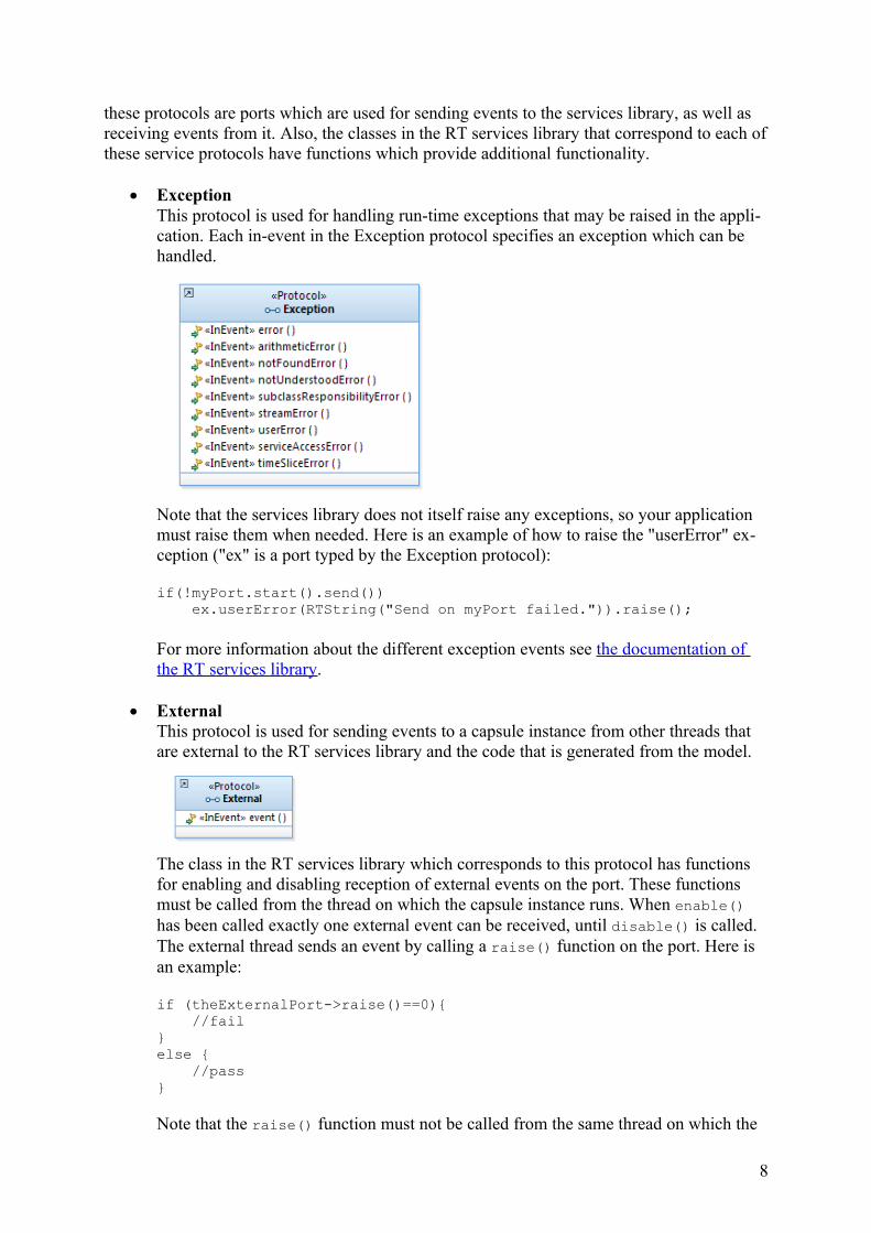
ExceptionThis protocol is used for handling run-time exceptions that may be raised in the appli-cation. Each in-event in the Exception protocol specifies an exception which can be handled.
Note that the services library does not itself raise any exceptions, so your application must raise them when needed. Here is an example of how to raise the "userError" ex-ception ("ex" is a port typed by the Exception protocol):
if(!myPort.start().send()) ex.userError(RTString("Send on myPort failed.")).raise();
For more information about the different exception events see the documentation of the RT services library.
ExternalThis protocol is used for sending events to a capsule instance from other threads that are external to the RT services library and the code that is generated from the model.
The class in the RT services library which corresponds to this protocol has functions for enabling and disabling reception of external events on the port. These functions must be called from the thread on which the capsule instance runs. When enable() has been called exactly one external event can be received, until disable() is called. The external thread sends an event by calling a raise() function on the port. Here is an example:
if (theExternalPort->raise()==0){ //fail } else { //pass }
Note that the raise() function must not be called from the same thread on which the
8
capsule instance runs.
FrameThis protocol does not contain any events, but the corresponding class in the RT ser-vices library provides several useful functions. Among others the functions for incar-nating a capsule are found here. Here is an example of code for incarnating a capsule instance into the optional capsule part "terminal" ("frame" is a port typed by the Frameprotocol):
RTActorId capsule_id = frame.incarnate(terminal);
For more information about the functions that are available on the Frame class, see thedocumentation of the RT services library.
LogThis protocol does not contain any events, but the corresponding class in the RT ser-vices library provides some functions related to logging text messages to the console. They can in particular be useful as a basic means of debugging or tracing. Here is an example ("logPort" is a port typed by the Log protocol):
logPort.log("Initialization completed!");
See the documentation of the RT services library for more information about what functions that are available in the Log class.
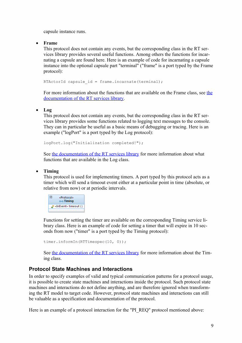
TimingThis protocol is used for implementing timers. A port typed by this protocol acts as a timer which will send a timeout event either at a particular point in time (absolute, or relative from now) or at periodic intervals.
Functions for setting the timer are available on the corresponding Timing service li-brary class. Here is an example of code for setting a timer that will expire in 10 sec-onds from now ("timer" is a port typed by the Timing protocol):
timer.informIn(RTTimespec(10, 0));
See the documentation of the RT services library for more information about the Tim-ing class.
Protocol State Machines and InteractionsIn order to specify examples of valid and typical communication patterns for a protocol usage,it is possible to create state machines and interactions inside the protocol. Such protocol state machines and interactions do not define anything, and are therefore ignored when transform-ing the RT model to target code. However, protocol state machines and interactions can still be valuable as a specification and documentation of the protocol.
Here is an example of a protocol interaction for the "PI_REQ" protocol mentioned above:
9
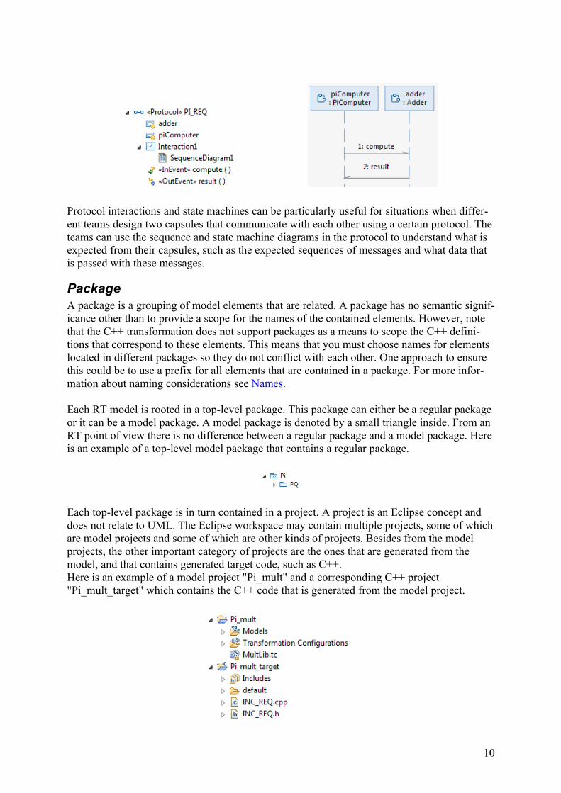
Protocol interactions and state machines can be particularly useful for situations when differ-ent teams design two capsules that communicate with each other using a certain protocol. Theteams can use the sequence and state machine diagrams in the protocol to understand what is expected from their capsules, such as the expected sequences of messages and what data that is passed with these messages.
PackageA package is a grouping of model elements that are related. A package has no semantic signif-icance other than to provide a scope for the names of the contained elements. However, note that the C++ transformation does not support packages as a means to scope the C++ defini-tions that correspond to these elements. This means that you must choose names for elements located in different packages so they do not conflict with each other. One approach to ensure this could be to use a prefix for all elements that are contained in a package. For more infor-mation about naming considerations see Names.
Each RT model is rooted in a top-level package. This package can either be a regular package or it can be a model package. A model package is denoted by a small triangle inside. From an RT point of view there is no difference between a regular package and a model package. Hereis an example of a top-level model package that contains a regular package.
Each top-level package is in turn contained in a project. A project is an Eclipse concept and does not relate to UML. The Eclipse workspace may contain multiple projects, some of whichare model projects and some of which are other kinds of projects. Besides from the model projects, the other important category of projects are the ones that are generated from the model, and that contains generated target code, such as C++. Here is an example of a model project "Pi_mult" and a corresponding C++ project "Pi_mult_target" which contains the C++ code that is generated from the model project.
10
ComponentWhile a package groups elements that are related in the design model, a component is a grouping concept for the deployment model. That is, elements that are related in a particular deployment of a model are said to belong to the same component. Since the same model can be deployed in multiple ways, an element may belong to more than one component.
Each component in an RT model is also a transformation configuration. A transformation configuration is a file (with the extension .tc or .tcjs) that contains all the information that is necessary to be able to transform the model elements that belong to that component. The out-come of such a transformation is typically a number of generated files, for example C++ files and makefiles. These files can then be processed by build tools (make, compiler etc.) to pro-duce the physical manifestation of the component. This could for example be a C++ exe-cutable or a library.
Components are edited in two ways:1. In UML component diagrams. Here it is possible to describe which components that
exist, what kind of components they are, and how they depend on each other.2. In the transformation configuration editor. Here it is possible to specify which source
model elements that belong to the component, as well as all the details about how to transform these elements to target files, and also how to build these target files.
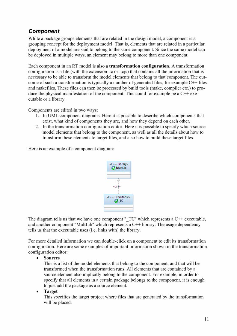
Here is an example of a component diagram:
The diagram tells us that we have one component "_TC" which represents a C++ executable, and another component "MultLib" which represents a C++ library. The usage dependency tells us that the executable uses (i.e. links with) the library.
For more detailed information we can double-click on a component to edit its transformation configuration. Here are some examples of important information shown in the transformation configuration editor:
SourcesThis is a list of the model elements that belong to the component, and that will be transformed when the transformation runs. All elements that are contained by a source element also implicitly belong to the component. For example, in order to specify that all elements in a certain package belongs to the component, it is enough to just add the package as a source element.
TargetThis specifies the target project where files that are generated by the transformation will be placed.
11
Top capsuleEach component that represents an executable (except test executables) must specify a top capsule. This is the capsule that will be incarnated by the RT services library when the executable starts to execute.
Artifact typeSpecifies the kind of component. This is the same information as is also shown in the component diagram.
Prerequisite transformation configurationsSpecifies other transformation configurations. This is the same information as is shown by means of usage dependencies in the component diagram. This information is used when generating a makefile during the transformation, to ensure that transfor-mation configurations run in the correct order.
Target configuration settingsThese settings are used to generate makefiles that specify how generated files shall bebuilt.
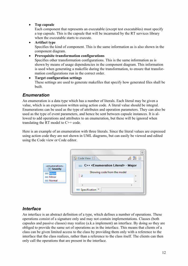
EnumerationAn enumeration is a data type which has a number of literals. Each literal may be given a value, which is an expression written using action code. A literal value should be integral. Enumerations can be used as the type of attributes and operation parameters. They can also beused as the type of event parameters, and hence be sent between capsule instances. It is al-lowed to add operations and attributes to an enumeration, but these will be ignored when translating the RT model to C++ code.
Here is an example of an enumeration with three literals. Since the literal values are expressedusing action code they are not shown in UML diagrams, but can easily be viewed and edited using the Code view or Code editor.
InterfaceAn interface is an abstract definition of a type, which defines a number of operations. These operations consist of a signature only and may not contain implementations. Classes (both capsules and passive classes) may realize (a.k.a implement) an interface. By doing so they areobliged to provide the same set of operations as in the interface. This means that clients of a class can be given limited access to the class by providing them only with a reference to the interface that the class realizes, rather than a reference to the class itself. The clients can then only call the operations that are present in the interface.
12

Consider this example:
A client which has a reference to a PC instance can call both the getData() and setData() operations, since they are both public. However, a client which only has been given a refer-ence to an instance typed by the realized interface Ifc, can only call the getData() operation since only that operation is available in the interface. The interface hence makes it possible to control which functionality of a class to expose to different users of the class.
It's also often useful to define interfaces to be realized by capsules. For example, if you need to pass a reference to a capsule instance to a passive class, it's recommended to let the capsuleimplement an interface which exposes only the operations that the passive class should be al-lowed to call. Thereby you can define more clearly what functionality the capsule exposes to the passive class, and you avoid to accidentally use other parts of the capsule implementation.
GeneralizationGeneralization relationships are used for inheriting structure and behavior from a general par-ent class, to specialized child classes. It is allowed to use generalizations both for capsules andpassive classes, but the parent and child classes must be of the same kind, i.e. either both cap-sules or both passive classes. In addition it’s also possible to use generalizations between in-terfaces.
A specialized child class may access all attributes and operations from the parent class, exceptthose that are declared private. Other things that are inherited are ports, the composite struc-ture (capsule parts and connectors) and the state machine.
Generalizations are shown in class diagrams. For example:
13
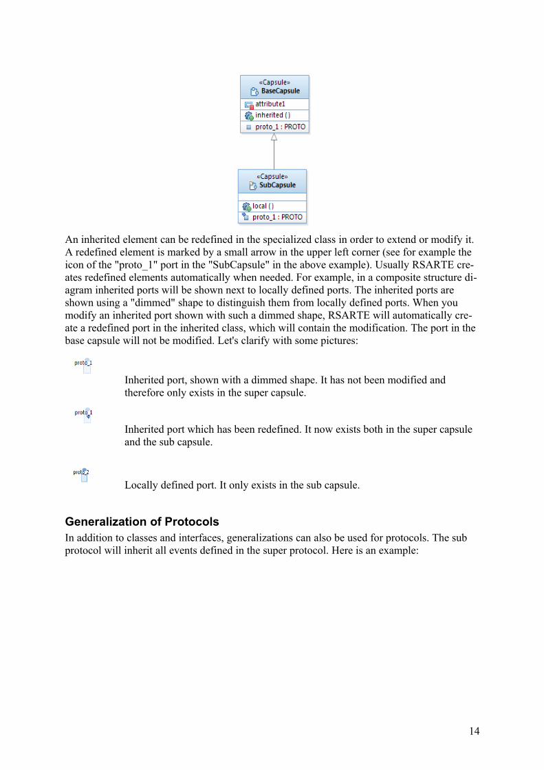
An inherited element can be redefined in the specialized class in order to extend or modify it. A redefined element is marked by a small arrow in the upper left corner (see for example the icon of the "proto_1" port in the "SubCapsule" in the above example). Usually RSARTE cre-ates redefined elements automatically when needed. For example, in a composite structure di-agram inherited ports will be shown next to locally defined ports. The inherited ports are shown using a "dimmed" shape to distinguish them from locally defined ports. When you modify an inherited port shown with such a dimmed shape, RSARTE will automatically cre-ate a redefined port in the inherited class, which will contain the modification. The port in the base capsule will not be modified. Let's clarify with some pictures:
Inherited port, shown with a dimmed shape. It has not been modified and therefore only exists in the super capsule.
Inherited port which has been redefined. It now exists both in the super capsule and the sub capsule.
Locally defined port. It only exists in the sub capsule.
Generalization of ProtocolsIn addition to classes and interfaces, generalizations can also be used for protocols. The sub protocol will inherit all events defined in the super protocol. Here is an example:
14
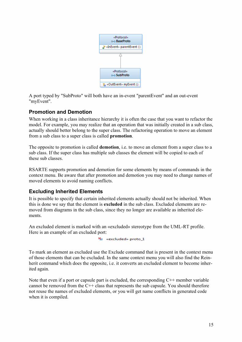
A port typed by "SubProto" will both have an in-event "parentEvent" and an out-event "myEvent".
Promotion and DemotionWhen working in a class inheritance hierarchy it is often the case that you want to refactor themodel. For example, you may realize that an operation that was initially created in a sub class,actually should better belong to the super class. The refactoring operation to move an element from a sub class to a super class is called promotion.
The opposite to promotion is called demotion, i.e. to move an element from a super class to a sub class. If the super class has multiple sub classes the element will be copied to each of these sub classes.
RSARTE supports promotion and demotion for some elements by means of commands in the context menu. Be aware that after promotion and demotion you may need to change names of moved elements to avoid naming conflicts.
Excluding Inherited ElementsIt is possible to specify that certain inherited elements actually should not be inherited. When this is done we say that the element is excluded in the sub class. Excluded elements are re-moved from diagrams in the sub class, since they no longer are available as inherited ele-ments.
An excluded element is marked with an «excluded» stereotype from the UML-RT profile. Here is an example of an excluded port:
To mark an element as excluded use the Exclude command that is present in the context menuof those elements that can be excluded. In the same context menu you will also find the Rein-herit command which does the opposite, i.e. it converts an excluded element to become inher-ited again.
Note that even if a port or capsule part is excluded, the corresponding C++ member variable cannot be removed from the C++ class that represents the sub capsule. You should therefore not reuse the names of excluded elements, or you will get name conflicts in generated code when it is compiled.
15
Inheritance RearrangementWhen a generalization relationship is deleted from the model, RSARTE will provide you witha possibility to automatically copy all inherited elements from the previous super class down to the sub class. This operation is known as absorption.
Absorption is also useful when a generalization relationship is moved from one sub class to another, since the effect for the previous sub class is the same as if the generalization was deleted. In addition, when moving a generalization it may also be useful to automatically ex-clude all elements from the super class in the new sub class.
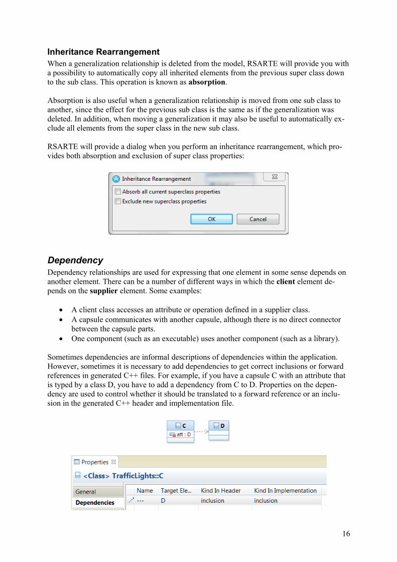
RSARTE will provide a dialog when you perform an inheritance rearrangement, which pro-vides both absorption and exclusion of super class properties:
DependencyDependency relationships are used for expressing that one element in some sense depends on another element. There can be a number of different ways in which the client element de-pends on the supplier element. Some examples:
A client class accesses an attribute or operation defined in a supplier class. A capsule communicates with another capsule, although there is no direct connector
between the capsule parts. One component (such as an executable) uses another component (such as a library).
Sometimes dependencies are informal descriptions of dependencies within the application. However, sometimes it is necessary to add dependencies to get correct inclusions or forward references in generated C++ files. For example, if you have a capsule C with an attribute that is typed by a class D, you have to add a dependency from C to D. Properties on the depen-dency are used to control whether it should be translated to a forward reference or an inclu-sion in the generated C++ header and implementation file.
16
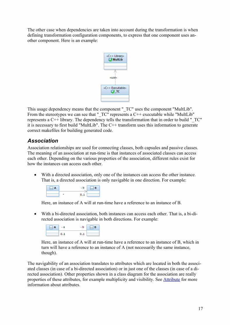
The other case when dependencies are taken into account during the transformation is when defining transformation configuration components, to express that one component uses an-other component. Here is an example:
This usage dependency means that the component "_TC" uses the component "MultLib". From the stereotypes we can see that "_TC" represents a C++ executable while "MultLib" represents a C++ library. The dependency tells the transformation that in order to build "_TC"it is necessary to first build "MultLib". The C++ transform uses this information to generate correct makefiles for building generated code.
AssociationAssociation relationships are used for connecting classes, both capsules and passive classes. The meaning of an association at run-time is that instances of associated classes can access each other. Depending on the various properties of the association, different rules exist for how the instances can access each other.
With a directed association, only one of the instances can access the other instance. That is, a directed association is only navigable in one direction. For example:
Here, an instance of A will at run-time have a reference to an instance of B.
With a bi-directed association, both instances can access each other. That is, a bi-di-rected association is navigable in both directions. For example:
Here, an instance of A will at run-time have a reference to an instance of B, which in turn will have a reference to an instance of A (not necessarily the same instance, though).
The navigability of an association translates to attributes which are located in both the associ-ated classes (in case of a bi-directed association) or in just one of the classes (in case of a di-rected association). Other properties shown in a class diagram for the association are really properties of these attributes, for example multiplicity and visibility. See Attribute for more information about attributes.
17
AttributeAttributes of a class define slots where at run-time data can be put in an instance of the class. The type of the data that is put in a slot must be compatible with the type of the attribute. All types from the action language may be used (both primitive types such as int or bool, as well as user-defined types such as enums, classes or typedefs). Types defined in the model may of course also be used, such as passive classes, interfaces and enumerations.
Attributes are shown in class diagrams, either in the attribute compartment of the class, or by means of an association line. These two visualizations are equivalent. For example, these two class diagrams have the same meaning:
If an attribute has composite aggregation it is a part. As this name indicates the class instancethat is put in the slot for a composite attribute has a lifetime relationship with the container class instance (it is a part of the container instance). If the container class instance is de-stroyed, so is the part instance.
If the type of a composite attribute is a capsule, the attribute is a capsule part. Capsule parts can be visualized in a composite structure diagram for the capsule. See Composite Structure for more about this.
There are three kinds of capsule parts:
1. Fixed capsule parts. By default capsule parts are fixed, meaning that they are created automatically when the container capsule is created, and destroyed when the container is destroyed. Fixed capsule parts by default have multiplicity 1.Here is an example of a fixed capsule part shown in a composite structure diagram:
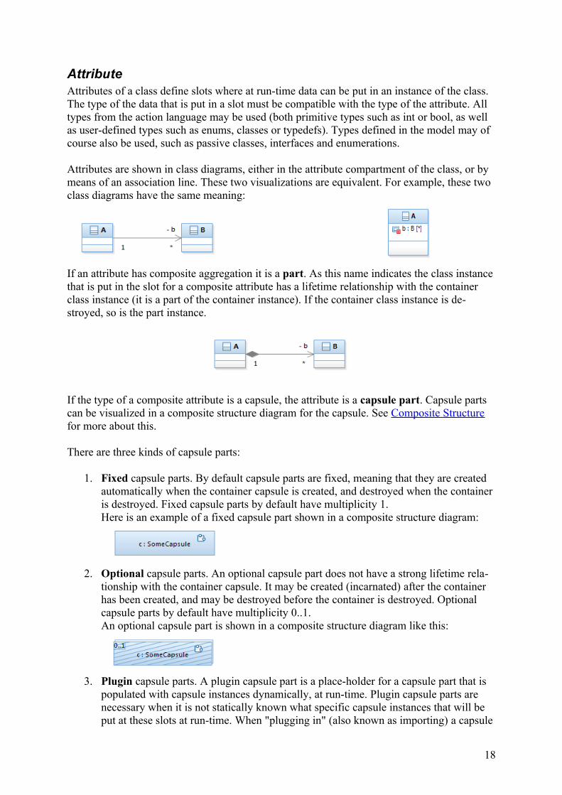
2. Optional capsule parts. An optional capsule part does not have a strong lifetime rela-tionship with the container capsule. It may be created (incarnated) after the container has been created, and may be destroyed before the container is destroyed. Optional capsule parts by default have multiplicity 0..1.An optional capsule part is shown in a composite structure diagram like this:
3. Plugin capsule parts. A plugin capsule part is a place-holder for a capsule part that is populated with capsule instances dynamically, at run-time. Plugin capsule parts are necessary when it is not statically known what specific capsule instances that will be put at these slots at run-time. When "plugging in" (also known as importing) a capsule
18
instance into a plugin capsule part, connector instances are automatically established to allow the capsule instance to take part in the communication that can take place on these connectors. Later the capsule instance can be removed (also known as deported) from the plugin capsule part, and then connector instances are automatically removed. Over time a capsule instance can move between different plugin capsule parts, and hence play different roles in the composite structure. The same capsule instance can be imported into more than one plugin capsule part. In general a capsule instance can be located in any number of plugin capsule parts, but at most in one optional or fixed capsule part. It is not allowed to import a capsule in-stance if one of its ports already is bound in its current location.Plugin capsule parts by default have multiplicity 0..1.A plugin capsule part is shown in a composite structure diagram like this:
For optional and plugin capsule parts the actual type of a capsule instance that is added to the capsule part may or may not be exactly the same as the type of the capsule part. A capsule part has a property Substitutable Type which can be edited using the Properties view. If this property is true, which is the default, then the type of a capsule instance only has to be com-patible with the type of the capsule part. If Substitutable Type is false, then the type of the in-stance has to match the type of the capsule part exactly.
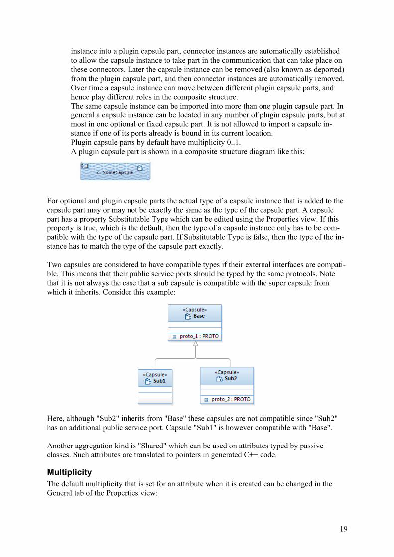
Two capsules are considered to have compatible types if their external interfaces are compati-ble. This means that their public service ports should be typed by the same protocols. Note that it is not always the case that a sub capsule is compatible with the super capsule from which it inherits. Consider this example:
Here, although "Sub2" inherits from "Base" these capsules are not compatible since "Sub2" has an additional public service port. Capsule "Sub1" is however compatible with "Base".
Another aggregation kind is "Shared" which can be used on attributes typed by passive classes. Such attributes are translated to pointers in generated C++ code.
MultiplicityThe default multiplicity that is set for an attribute when it is created can be changed in the General tab of the Properties view:
19
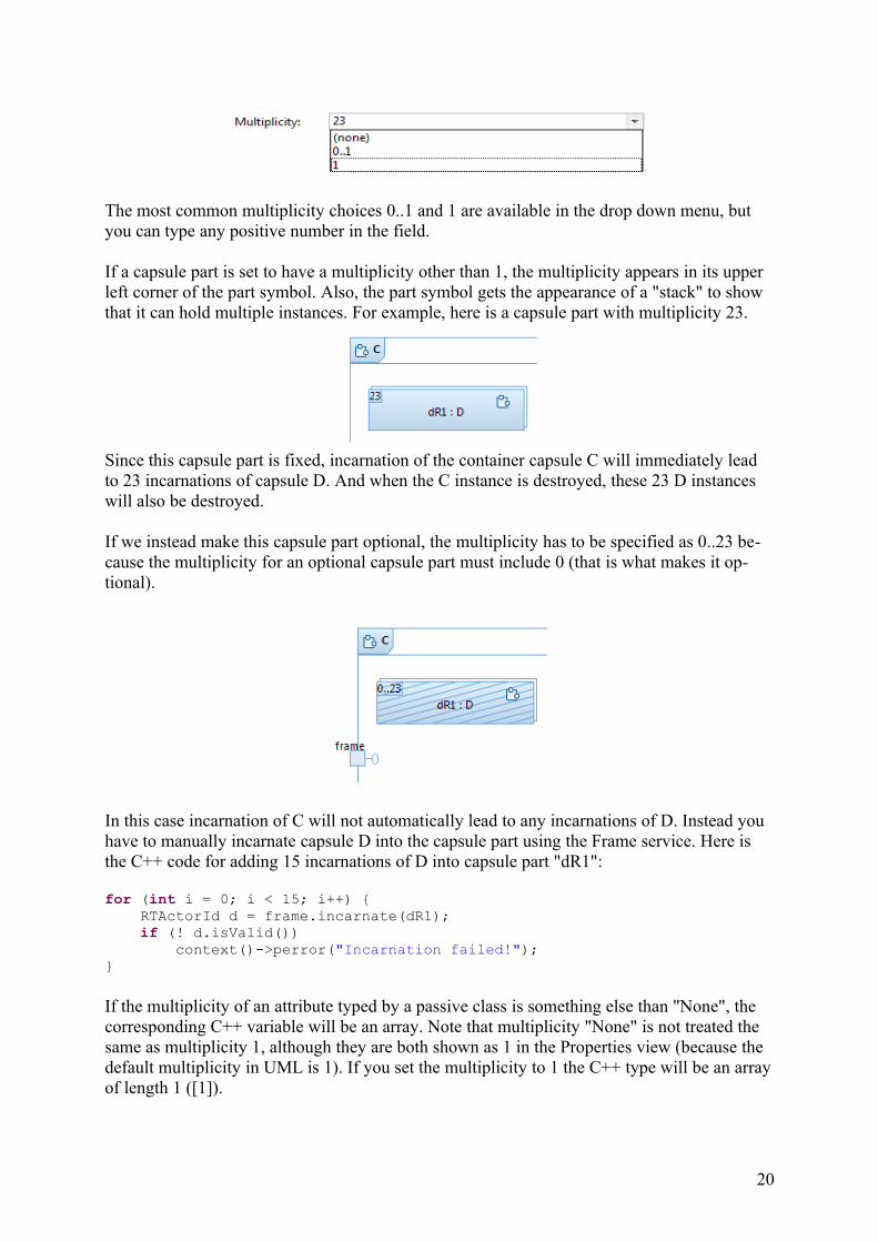
The most common multiplicity choices 0..1 and 1 are available in the drop down menu, but you can type any positive number in the field.
If a capsule part is set to have a multiplicity other than 1, the multiplicity appears in its upper left corner of the part symbol. Also, the part symbol gets the appearance of a "stack" to show that it can hold multiple instances. For example, here is a capsule part with multiplicity 23.
Since this capsule part is fixed, incarnation of the container capsule C will immediately lead to 23 incarnations of capsule D. And when the C instance is destroyed, these 23 D instances will also be destroyed.
If we instead make this capsule part optional, the multiplicity has to be specified as 0..23 be-cause the multiplicity for an optional capsule part must include 0 (that is what makes it op-tional).
In this case incarnation of C will not automatically lead to any incarnations of D. Instead you have to manually incarnate capsule D into the capsule part using the Frame service. Here is the C++ code for adding 15 incarnations of D into capsule part "dR1":
for (int i = 0; i < 15; i++) { RTActorId d = frame.incarnate(dR1); if (! d.isValid()) context()->perror("Incarnation failed!"); }
If the multiplicity of an attribute typed by a passive class is something else than "None", the corresponding C++ variable will be an array. Note that multiplicity "None" is not treated the same as multiplicity 1, although they are both shown as 1 in the Properties view (because the default multiplicity in UML is 1). If you set the multiplicity to 1 the C++ type will be an arrayof length 1 ([1]).
20
PortPorts are special kinds of attributes of a capsule. They are part attributes, and hence they are owned by the capsule instance in the sense that they are created when the capsule instance is created and destroyed when it is destroyed. Ports are typed by protocols, which specify which events that may be sent to or from the port (see Protocol).
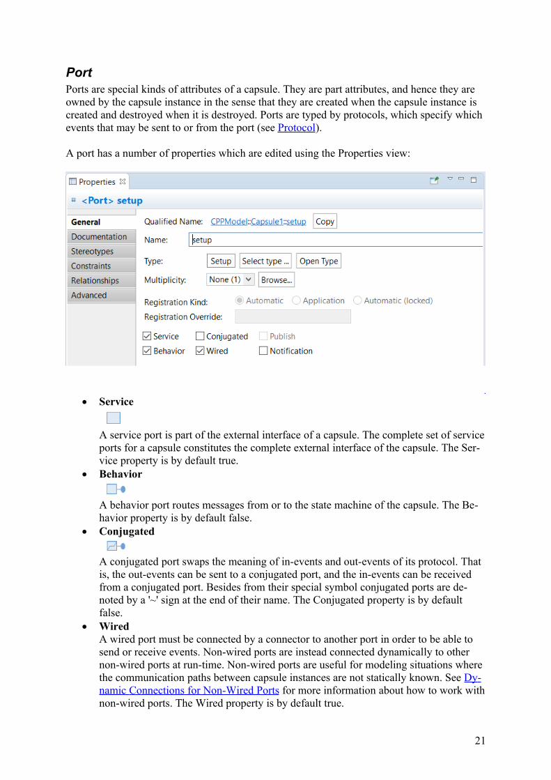
A port has a number of properties which are edited using the Properties view:
Service
A service port is part of the external interface of a capsule. The complete set of serviceports for a capsule constitutes the complete external interface of the capsule. The Ser-vice property is by default true.
Behavior
A behavior port routes messages from or to the state machine of the capsule. The Be-havior property is by default false.
Conjugated
A conjugated port swaps the meaning of in-events and out-events of its protocol. That is, the out-events can be sent to a conjugated port, and the in-events can be received from a conjugated port. Besides from their special symbol conjugated ports are de-noted by a '~' sign at the end of their name. The Conjugated property is by default false.
WiredA wired port must be connected by a connector to another port in order to be able to send or receive events. Non-wired ports are instead connected dynamically to other non-wired ports at run-time. Non-wired ports are useful for modeling situations where the communication paths between capsule instances are not statically known. See Dy-namic Connections for Non-Wired Ports for more information about how to work withnon-wired ports. The Wired property is by default true.
21
PublishA non-wired port can either be published or non-published depending on the role its container capsule instance plays in a client/server communication architecture. See Dynamic Connections for Non-Wired Ports for more information. The Publish prop-erty is by default false.
NotificationIf this property is true, the RT services library will send notification events when the port gets connected or disconnected. These events are called rtBound and rtUnbound and are described in The rtBound and rtUnbound Events. The Notification property is by default true.
The messages for all kinds of events (except messages for external events; see the External protocol in RT Service Protocols) are sent from a sender capsule instance out through one of its behavior ports. The messages then get routed through a path of connections (correspondingto either statically defined connectors, or dynamically created connections for non-wired ports). During this routing a message may pass a number of relay ports which funnel the message to or from capsule instances located in capsule parts. Ultimately the message reachesa behavior port on the receiver capsule instance, and will then eventually be handled by the state machine of that capsule instance.
Note that if a message arrives at a relay port without any connections, the path from the sender to the receiver is broken and the message will be lost. This usually indicates a problem in the design of the application.
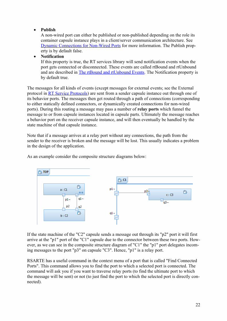
As an example consider the composite structure diagrams below:
If the state machine of the "C2" capsule sends a message out through its "p2" port it will first arrive at the "p1" port of the "C1" capsule due to the connector between these two ports. How-ever, as we can see in the composite structure diagram of "C1" the "p1" port delegates incom-ing messages to the port "p3" on capsule "C3". Hence, "p1" is a relay port.
RSARTE has a useful command in the context menu of a port that is called "Find Connected Ports". This command allows you to find the port to which a selected port is connected. The command will ask you if you want to traverse relay ports (to find the ultimate port to which the message will be sent) or not (to just find the port to which the selected port is directly con-nected).
22
In the composite structure diagram for "C1" above we can also see that a connector is missingbetween the "q1" and the "q3" ports. Hence, the communication path between "q2" and "q3" is broken, and if a message is sent out through "q2" an error message will be printed at run-time to inform that the port is not connected.
Just like regular attributes a port may have non-single multiplicity (N > 1). This is for exam-ple useful in order to let multiple clients connect to a single server port. The multiplicity of the server port then decides the maximum number of simultaneously connected clients. Ports with non-single multiplicity are sometimes said to be replicated (because they may contain many "replicas" of the port). The replication factor denotes the current number of port in-stances (i.e. connections) for the port. The graphical notation for a port with non-single multi-plicity is a "stack of ports":
Typically the port multiplicity is something that is statically specified in the design. However,it is possible to change the multiplicity at run-time by calling a resize() function on the port.Doing so may give room for more connections (if the multiplicity upper bound is increased) but may also lead to dropped connections (if the multiplicity upper bound is decreased).
Dynamic Connections for Non-Wired PortsContrary to wired ports, which are connected automatically when capsule instances are cre-ated based on the static connector structure, non-wired ports are programmatically connected (and disconnected) at run-time by the use of services provided by the RT services library. Onecommon usage of non-wired ports are for modeling client/server designs, where a shared ser-vice provided by a server is accessed by a number of clients. The server is referred to as the publisher, and the clients are referred to as subscribers.
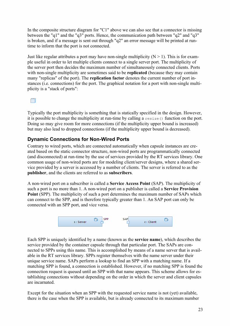
A non-wired port on a subscriber is called a Service Access Point (SAP). The multiplicity of such a port is no more than 1. A non-wired port on a publisher is called a Service Provision Point (SPP). The multiplicity of such a port determines the maximum number of SAPs which can connect to the SPP, and is therefore typically greater than 1. An SAP port can only be connected with an SPP port, and vice versa.
Each SPP is uniquely identified by a name (known as the service name), which describes the service provided by the container capsule through that particular port. The SAPs are con-nected to SPPs using this name. This is accomplished by means of a name server that is avail-able in the RT services library. SPPs register themselves with the name server under their unique service name. SAPs perform a lookup to find an SPP with a matching name. If a matching SPP is found, a connection is established. However, if no matching SPP is found theconnection request is queued until an SPP with that name appears. This scheme allows for es-tablishing connections without depending on the order in which the server and client capsules are incarnated.
Except for the situation when an SPP with the requested service name is not (yet) available, there is the case when the SPP is available, but is already connected to its maximum number
23
of SAPs (as specified by its port multiplicity upper bound). Also in this case the connection request will be queued. If, at a later point in time, one of the already connected SAPs discon-nect from the SPP, one of the pending connection requests can be processed to connect a wait-ing SAP. Another thing that can happen is that the port multiplicity of the SPP is dynamically increased, which gives room for more SAPs to connect.
Each connection request made by an SAP can provide a string which describes the connec-tion. This string is appended to the service name to create a registration string. It has the fol-lowing format:
<service name>:<connection string>
The service name string is case sensitive, while the connection string is interpreted by the ser-vice and hence may have any format.
Note that connections of non-wired ports always are established by the RT services library. The responsibility of the application is only to register the ports, which enables the RT ser-vices library to perform the connections (immediately, or at some later point in time). In the same way, ports can be deregistered, which may lead to that existing connections are removedby the RT services library. It is allowed for the same port to register itself multiple times us-ing different service names. In this case, the port will be automatically deregistered for its pre-vious service name, before it is registered with the new service name.
There are three possible ways in which the registration may occur for a non-wired port (repre-sented by a property on the port):
Automatic. This is the default registration kind, and means that the port registers itselfat the time when its containing capsule instance is initialized. The service name used isthe name of the port. With this kind of registration the port's Publish property will be used for determining if a port is an SPP (Publish set) or an SAP (Publish unset).
Application. Ports with this registration kind are manually registered using the reg-isterSPP() and registerSAP() functions, which are available on non-wired ports. These functions take the registration string as their argument.For example:sppPort.registerSPP("myService:/x/y/z");sapPort.registerSAP("myService:/x/y/z");
With this kind of registration you don't need to set the Publish property since the above function calls are what decides whether a port becomes an SPP or an SAP.
Automatic (locked). With this registration kind the port is registered just like with au-tomatic registration. But in addition the registration is "locked" meaning that any later attempt to deregister the port (or register it under a different name) will fail.
For both kinds of automatic registration it is possible to specify a different name to register than the port name. The property used for this is called Registration Override.
Composite StructureA simple capsule which only handles a small number of events, may be able to handle all these events using a single state machine. However, when new ports are added (or new eventsin protocols typing existing ports), the capsule interface grows and the state machine has to
24
grow with it, since there will be more events for it to handle. Eventually a point is reached where it will not be practical for a capsule to handle any more events in its own state machine,because it has grown too large or complex. If not before, this is the time to define a compositestructure for the capsule.
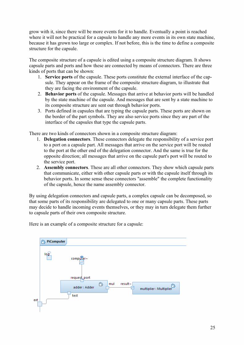
The composite structure of a capsule is edited using a composite structure diagram. It shows capsule parts and ports and how these are connected by means of connectors. There are three kinds of ports that can be shown:
1. Service ports of the capsule. These ports constitute the external interface of the cap-sule. They appear on the frame of the composite structure diagram, to illustrate that they are facing the environment of the capsule.
2. Behavior ports of the capsule. Messages that arrive at behavior ports will be handled by the state machine of the capsule. And messages that are sent by a state machine to its composite structure are sent out through behavior ports.
3. Ports defined in capsules that are typing the capsule parts. These ports are shown on the border of the part symbols. They are also service ports since they are part of the interface of the capsules that type the capsule parts.
There are two kinds of connectors shown in a composite structure diagram:1. Delegation connectors. These connectors delegate the responsibility of a service port
to a port on a capsule part. All messages that arrive on the service port will be routed to the port at the other end of the delegation connector. And the same is true for the opposite direction; all messages that arrive on the capsule part's port will be routed to the service port.
2. Assembly connectors. These are all other connectors. They show which capsule parts that communicate, either with other capsule parts or with the capsule itself through its behavior ports. In some sense these connectors "assemble" the complete functionality of the capsule, hence the name assembly connector.
By using delegation connectors and capsule parts, a complex capsule can be decomposed, so that some parts of its responsibility are delegated to one or many capsule parts. These parts may decide to handle incoming events themselves, or they may in turn delegate them further to capsule parts of their own composite structure.
Here is an example of a composite structure for a capsule:
25

We see that this capsule has one service port "ext" which is shown on the diagram frame. A delegation connector connects this port with a port "test" that is defined in the capsule "Adder" that types the capsule part "adder". The diagram also shows two assembly connec-tors. One of them connects the "request_port" with "computer", which is a behavior port de-fined on the "PiComputer" capsule itself. The other assembly connector provides a means for the "adder" to communicate with the "multiplier" through the "mul" and "result" ports.
Since events is the only means for communicating with capsule instances, a composite dia-gram provides a useful view over possible communication paths at a particular level of ab-straction. However, if non-wired ports are used there may be additional connections dynami-cally established at run-time.
OperationOperations of a class may contain a body consisting of action code that will be executed whenthe operation is invoked. Such a body is called an OpaqueBehavior in UML. The separation of the operation signature from the operation implementation into two separate model ele-ments may seem confusing for a Java programmer, but should be more familiar for a C++ programmer (since C++ uses the same separation of function declarations and implementa-tion).
Operations may have parameters which provide a means for passing data to its implementa-tion body. By default a parameter has "In" direction which means it can only convey data from the caller of the operation to the implementation of the operation. UML allows you to specify also In/Out or Out parameters as a means to convey data also in the other direction, from the implementation to the caller. However, in an RT model these directions have no im-pact on generated code, although you can still use them as a kind of documentation. Instead you have to use mechanisms from the action language to achieve the same thing. For exam-ple, in C++ you can use a reference parameter (&) to be able to assign a value to the parame-ter which can be obtained by the caller.
An operation may also have a single Return parameter, which specifies the type of the value to which a call of the operation will evaluate. If there is no Return parameter, or the Return parameter is typed by "void", then the operation cannot be called in contexts where a value is required, such as the right-hand side of an assignment.
Operations that are contained in abstract classes may be marked as Pure Virtual. Such opera-tions are not allowed to have an implementation body, and just express that concrete sub-classes must provide an overriding implementation for them.
By default an operation is treated as non-virtual in C++. To make it virtual you must set the property Virtual. For C++ RT models this property must be used in order to get polymorphic behavior when invoking operations.
If an operation is not supposed to modify any of the attributes of its object, it should be speci-fied to be a Const operation. This corresponds to a "const" member function in C++.
Operations can be specified to be Static, which means that their implementations do not need an object. Static operations can thus not access any non-static attributes, or invoke any non-static operations.
26

An operation for which the Inline property is set will be translated to an inline function in C++.
A special kind of operations are the trigger operations which are used for triggering transi-tions of a passive class state machine. See State Machine in Passive Class for more informa-tion.
Constructor and DestructorFor a C++ RT model it is important to be able to specify constructors and a destructor for a class. These are represented in the model as regular operations but with certain constraints (the same as in C++):
A constructor has the same name as the container class. It should not have a return pa-rameter.
A destructor has the same name as the container class but with a '~' prefix.
Note that the use of the '~' prefix is ambiguous with the UML syntax where '~' is used for specifying package visibility (something that is not used in an RT model). To handle this am-biguity it is important that you specify the '~' as part of the name when editing an operation signature.
Wrong! This creates an operation 'foo' with package visibility.
Correct! This creates a destructor 'foo' with public visibility.
Thrown ExceptionsAn operation may specify a list of exception types which its implementation can throw. UML uses a property called "RaisedExceptions" for this, which is edited using the tab "Exceptions" in the Properties view. However, this property is not supported by RSARTE when generating target code from the model. Instead you specify exception types for an operation using opera-tion parameters for which the property "Is Exception" is set to true. You also need to set the property "Declare Exceptions" on the operation to true. This property is found in the "C++ General" tab. Here is an example:
The types of the exception parameters are the exception types which the operation will throw. The above operation is translated by the C++ code generator to the following operation:
void foo( void ) throw( int * );
EventAn event specifies communication between capsules. The communication is based on mes-sages that are sent from one capsule instance to another. You can think of an event as the specification of certain kinds of messages, just like a class is the specification of certain kinds
27
of instances. So while an event is a design-time concept, a message is the corresponding run-time concept.
We often say that events are sent and received. However, what we really mean by sending an event is that a message is created for the event, and then that message is what gets sent. In the same way receiving an event really means that we receive a message for the event.
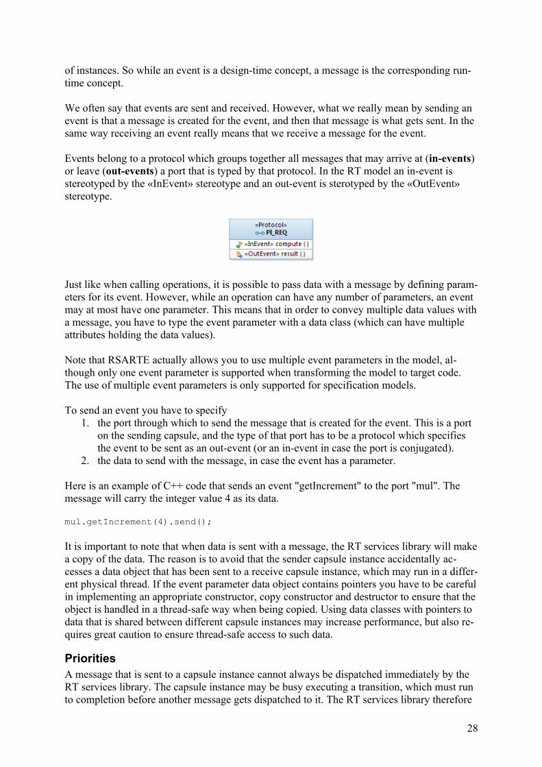
Events belong to a protocol which groups together all messages that may arrive at (in-events) or leave (out-events) a port that is typed by that protocol. In the RT model an in-event is stereotyped by the «InEvent» stereotype and an out-event is sterotyped by the «OutEvent» stereotype.
Just like when calling operations, it is possible to pass data with a message by defining param-eters for its event. However, while an operation can have any number of parameters, an event may at most have one parameter. This means that in order to convey multiple data values witha message, you have to type the event parameter with a data class (which can have multiple attributes holding the data values).
Note that RSARTE actually allows you to use multiple event parameters in the model, al-though only one event parameter is supported when transforming the model to target code. The use of multiple event parameters is only supported for specification models.
To send an event you have to specify1. the port through which to send the message that is created for the event. This is a port
on the sending capsule, and the type of that port has to be a protocol which specifies the event to be sent as an out-event (or an in-event in case the port is conjugated).
2. the data to send with the message, in case the event has a parameter.
Here is an example of C++ code that sends an event "getIncrement" to the port "mul". The message will carry the integer value 4 as its data.
mul.getIncrement(4).send();
It is important to note that when data is sent with a message, the RT services library will makea copy of the data. The reason is to avoid that the sender capsule instance accidentally ac-cesses a data object that has been sent to a receive capsule instance, which may run in a differ-ent physical thread. If the event parameter data object contains pointers you have to be carefulin implementing an appropriate constructor, copy constructor and destructor to ensure that theobject is handled in a thread-safe way when being copied. Using data classes with pointers to data that is shared between different capsule instances may increase performance, but also re-quires great caution to ensure thread-safe access to such data.
PrioritiesA message that is sent to a capsule instance cannot always be dispatched immediately by the RT services library. The capsule instance may be busy executing a transition, which must run to completion before another message gets dispatched to it. The RT services library therefore
28
maintains a queue of messages which are waiting to be dispatched. By default messages are ordered in this queue according to their time of arrival, so that the first message that was placed in the queue also is the first message to be dispatched. Note that in a real-time applica-tion there is no guarantee that messages arrive to a destination capsule instance in the same order as they were sent. Messages can hence only be ordered based on when they actually ar-rived to the receiver capsule instance.
It is possible to send a message with a non-default priority in order to tell the RT services li-brary to order it in the message queue differently upon arrival. A message with a higher prior-ity will be placed before a message with a lower priority. The following priority levels may beused:
Panic. This is the highest possible priority for user-defined messages. Use this only to handle emergencies.
High. This is a higher than normal priority to be used for high-priority messages. General. This is the default priority level which is suitable for most messages. Low. This is a lower than normal priority to be used for low-priority messages. Background. This is the lowest possible priority. Use this to handle background-type
of activities.
In addition to these five priority levels, there are two system-level priorities which are higher than all the above; System and Synchronous. These are used internally by the RT services li-brary, and cannot be used when sending user-defined messages.
Extensive use of message priorities in a real-time application may be an indication of a designproblem. It is recommended to stick to the default priority level as much as possible, or at least avoid using the high and low extremes to save room for future design changes.
The rtBound and rtUnbound EventsThe RT service library defines two special events which implicitly are available in any user-defined protocol:
rtBound rtUnbound
Messages for these events are sent by the RT services library to notify a capsule instance that one of its ports has become bound to or unbound from another port. rtBound is sent to a port at System priority when that port gets connected (i.e. bound to another remote port). This is useful information for the capsule since it then knows it can start sending events through that port. rtUnbound is sent to a port at Background priority when that port gets disconnected (i.e. unbound). The capsule should stop sending events on the port once rtUnbound has been re-ceived.
If the Notification property of a port is set to false, the RT services library will not send these notification events to the port.
State MachineState machines are used for specifying the behavior of classes. Both passive classes and cap-sule classes may have a state machine. In addition it is also possible to add a state machine to a protocol, but such a state machine does not specify any behavior, but rather serves as a kind of documentation for the protocol. See Protocol State Machines and Interactions for more in-formation about protocol state machines.
29
In this chapter we will focus on state machines in capsules. The use of state machines in pas-sive classes is described in State Machine in Passive Class.
A state machine consists of states, pseudo states and transitions. During the lifetime of a capsule instance its state machine will transition between the various states, as a consequence of receiving messages on the behavior ports. When transitioning between states one or severalsnippets of action code may execute. Such code may for example send messages to other cap-sule instances.
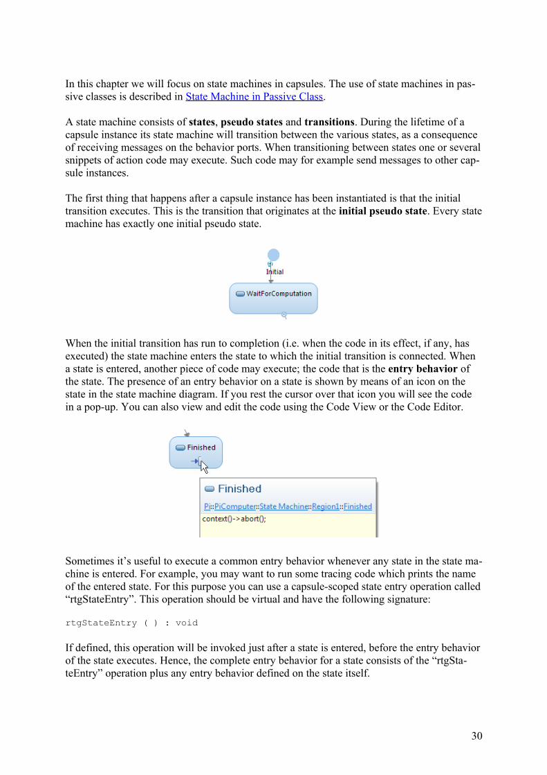
The first thing that happens after a capsule instance has been instantiated is that the initial transition executes. This is the transition that originates at the initial pseudo state. Every statemachine has exactly one initial pseudo state.
When the initial transition has run to completion (i.e. when the code in its effect, if any, has executed) the state machine enters the state to which the initial transition is connected. When a state is entered, another piece of code may execute; the code that is the entry behavior of the state. The presence of an entry behavior on a state is shown by means of an icon on the state in the state machine diagram. If you rest the cursor over that icon you will see the code in a pop-up. You can also view and edit the code using the Code View or the Code Editor.
Sometimes it’s useful to execute a common entry behavior whenever any state in the state ma-chine is entered. For example, you may want to run some tracing code which prints the name of the entered state. For this purpose you can use a capsule-scoped state entry operation called“rtgStateEntry”. This operation should be virtual and have the following signature:
rtgStateEntry ( ) : void
If defined, this operation will be invoked just after a state is entered, before the entry behaviorof the state executes. Hence, the complete entry behavior for a state consists of the “rtgSta-teEntry” operation plus any entry behavior defined on the state itself.
30
Until a message arrives at one of the behavior ports of the capsule, the state machine will re-main in its current state. During this time it does not perform any actions.When a message arrives, one of the outgoing transitions from the current state may be trig-gered. If this happens, the code in the exit behavior of the state will execute, followed by the code in the effect of the transition. Finally, the state to which the transition leads will be en-tered (which will cause its entry behavior code to execute). During the entire process of tran-sitioning from one state to another, the state machine will not be interrupted even if a messagewith a higher priority arrives at a behavior port. This principle is known as run-to-comple-tion and is important to guarantee the integrity of the real-time application. However, the principle also means that the code that runs while transitioning between states (i.e. the exit be-havior of the from-state, the transition effect and the entry behavior of the to-state) should not take too long time, because during this time no other message can be processed in any of the capsule instances that are run by the same physical thread. To ensure good responsiveness of the application transition-triggered code should therefore only perform quick tasks. If long-running tasks have to be performed, they should be handled by a separate capsule running in adifferent physical thread.
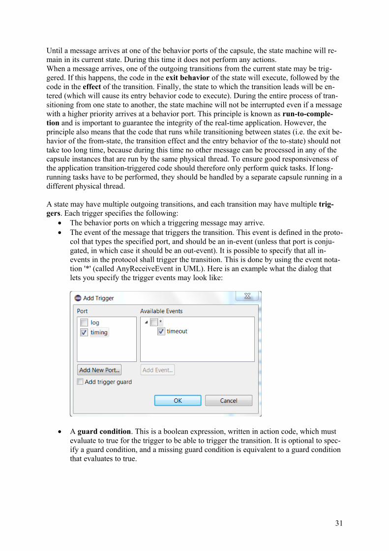
A state may have multiple outgoing transitions, and each transition may have multiple trig-gers. Each trigger specifies the following:
The behavior ports on which a triggering message may arrive. The event of the message that triggers the transition. This event is defined in the proto-
col that types the specified port, and should be an in-event (unless that port is conju-gated, in which case it should be an out-event). It is possible to specify that all in-events in the protocol shall trigger the transition. This is done by using the event nota-tion '*' (called AnyReceiveEvent in UML). Here is an example what the dialog that lets you specify the trigger events may look like:
A guard condition. This is a boolean expression, written in action code, which must evaluate to true for the trigger to be able to trigger the transition. It is optional to spec-ify a guard condition, and a missing guard condition is equivalent to a guard condition that evaluates to true.
31
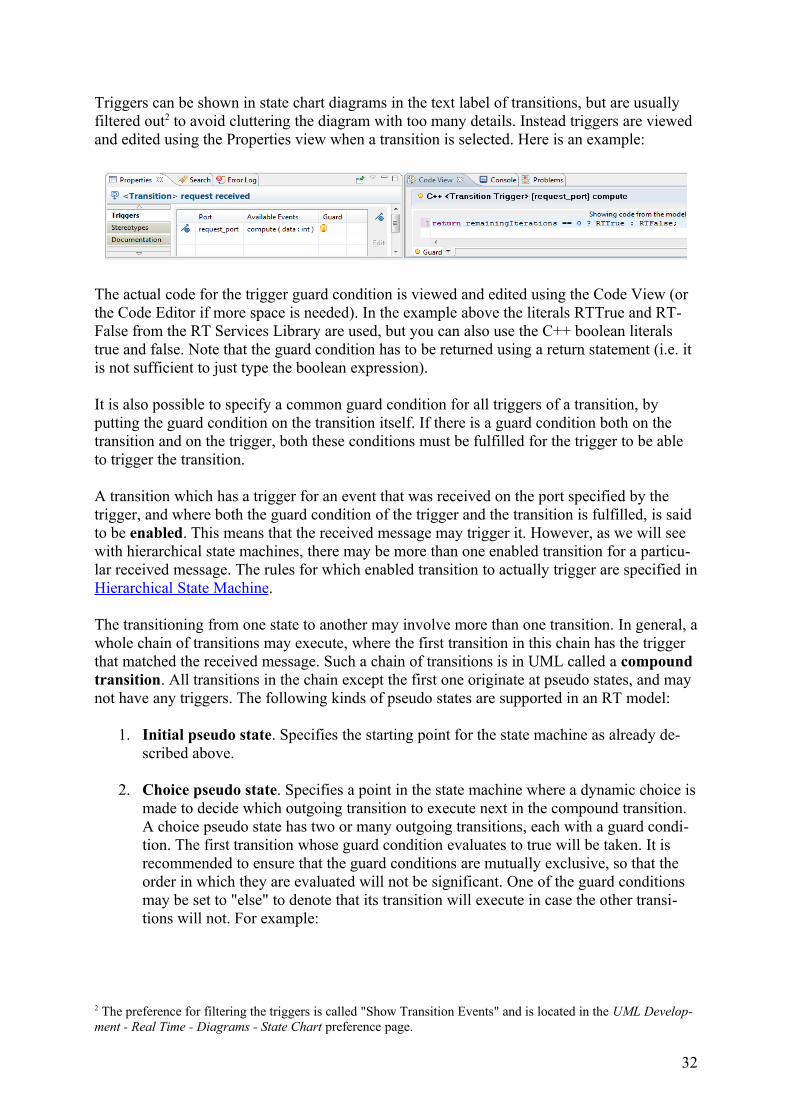
Triggers can be shown in state chart diagrams in the text label of transitions, but are usually filtered out2 to avoid cluttering the diagram with too many details. Instead triggers are viewed and edited using the Properties view when a transition is selected. Here is an example:
The actual code for the trigger guard condition is viewed and edited using the Code View (or the Code Editor if more space is needed). In the example above the literals RTTrue and RT-False from the RT Services Library are used, but you can also use the C++ boolean literals true and false. Note that the guard condition has to be returned using a return statement (i.e. it is not sufficient to just type the boolean expression).
It is also possible to specify a common guard condition for all triggers of a transition, by putting the guard condition on the transition itself. If there is a guard condition both on the transition and on the trigger, both these conditions must be fulfilled for the trigger to be able to trigger the transition.
A transition which has a trigger for an event that was received on the port specified by the trigger, and where both the guard condition of the trigger and the transition is fulfilled, is said to be enabled. This means that the received message may trigger it. However, as we will see with hierarchical state machines, there may be more than one enabled transition for a particu-lar received message. The rules for which enabled transition to actually trigger are specified inHierarchical State Machine.
The transitioning from one state to another may involve more than one transition. In general, awhole chain of transitions may execute, where the first transition in this chain has the trigger that matched the received message. Such a chain of transitions is in UML called a compound transition. All transitions in the chain except the first one originate at pseudo states, and may not have any triggers. The following kinds of pseudo states are supported in an RT model:
1. Initial pseudo state. Specifies the starting point for the state machine as already de-scribed above.
2. Choice pseudo state. Specifies a point in the state machine where a dynamic choice ismade to decide which outgoing transition to execute next in the compound transition. A choice pseudo state has two or many outgoing transitions, each with a guard condi-tion. The first transition whose guard condition evaluates to true will be taken. It is recommended to ensure that the guard conditions are mutually exclusive, so that the order in which they are evaluated will not be significant. One of the guard conditions may be set to "else" to denote that its transition will execute in case the other transi-tions will not. For example:
2 The preference for filtering the triggers is called "Show Transition Events" and is located in the UML Develop-ment - Real Time - Diagrams - State Chart preference page.
32
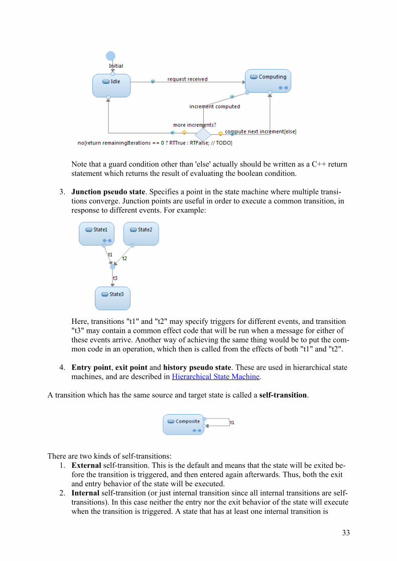
Note that a guard condition other than 'else' actually should be written as a C++ return statement which returns the result of evaluating the boolean condition.
3. Junction pseudo state. Specifies a point in the state machine where multiple transi-tions converge. Junction points are useful in order to execute a common transition, in response to different events. For example:
Here, transitions "t1" and "t2" may specify triggers for different events, and transition "t3" may contain a common effect code that will be run when a message for either of these events arrive. Another way of achieving the same thing would be to put the com-mon code in an operation, which then is called from the effects of both "t1" and "t2".
4. Entry point, exit point and history pseudo state. These are used in hierarchical state machines, and are described in Hierarchical State Machine.
A transition which has the same source and target state is called a self-transition.
There are two kinds of self-transitions:1. External self-transition. This is the default and means that the state will be exited be-
fore the transition is triggered, and then entered again afterwards. Thus, both the exit and entry behavior of the state will be executed.
2. Internal self-transition (or just internal transition since all internal transitions are self-transitions). In this case neither the entry nor the exit behavior of the state will executewhen the transition is triggered. A state that has at least one internal transition is
33
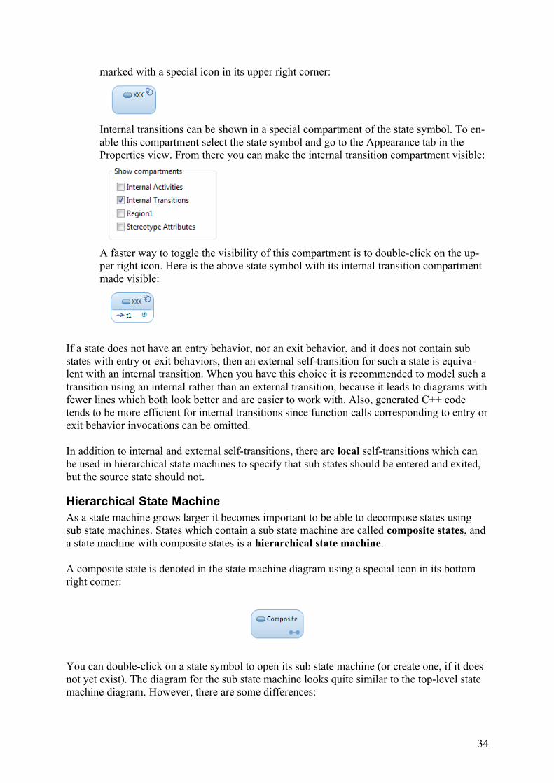
marked with a special icon in its upper right corner:
Internal transitions can be shown in a special compartment of the state symbol. To en-able this compartment select the state symbol and go to the Appearance tab in the Properties view. From there you can make the internal transition compartment visible:
A faster way to toggle the visibility of this compartment is to double-click on the up-per right icon. Here is the above state symbol with its internal transition compartment made visible:
If a state does not have an entry behavior, nor an exit behavior, and it does not contain sub states with entry or exit behaviors, then an external self-transition for such a state is equiva-lent with an internal transition. When you have this choice it is recommended to model such atransition using an internal rather than an external transition, because it leads to diagrams withfewer lines which both look better and are easier to work with. Also, generated C++ code tends to be more efficient for internal transitions since function calls corresponding to entry orexit behavior invocations can be omitted.
In addition to internal and external self-transitions, there are local self-transitions which can be used in hierarchical state machines to specify that sub states should be entered and exited, but the source state should not.
Hierarchical State MachineAs a state machine grows larger it becomes important to be able to decompose states using sub state machines. States which contain a sub state machine are called composite states, and a state machine with composite states is a hierarchical state machine.
A composite state is denoted in the state machine diagram using a special icon in its bottom right corner:
You can double-click on a state symbol to open its sub state machine (or create one, if it does not yet exist). The diagram for the sub state machine looks quite similar to the top-level state machine diagram. However, there are some differences:
34
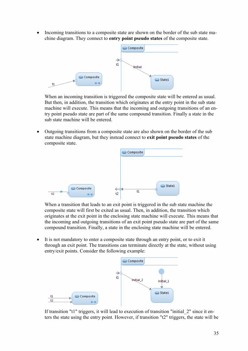
Incoming transitions to a composite state are shown on the border of the sub state ma-chine diagram. They connect to entry point pseudo states of the composite state.
When an incoming transition is triggered the composite state will be entered as usual. But then, in addition, the transition which originates at the entry point in the sub state machine will execute. This means that the incoming and outgoing transitions of an en-try point pseudo state are part of the same compound transition. Finally a state in the sub state machine will be entered.
Outgoing transitions from a composite state are also shown on the border of the sub state machine diagram, but they instead connect to exit point pseudo states of the composite state.
When a transition that leads to an exit point is triggered in the sub state machine the composite state will first be exited as usual. Then, in addition, the transition which originates at the exit point in the enclosing state machine will execute. This means thatthe incoming and outgoing transitions of an exit point pseudo state are part of the samecompound transition. Finally, a state in the enclosing state machine will be entered.
It is not mandatory to enter a composite state through an entry point, or to exit it through an exit point. The transitions can terminate directly at the state, without using entry/exit points. Consider the following example:
If transition "t1" triggers, it will lead to execution of transition "initial_2" since it en-ters the state using the entry point. However, if transition "t2" triggers, the state will be
35
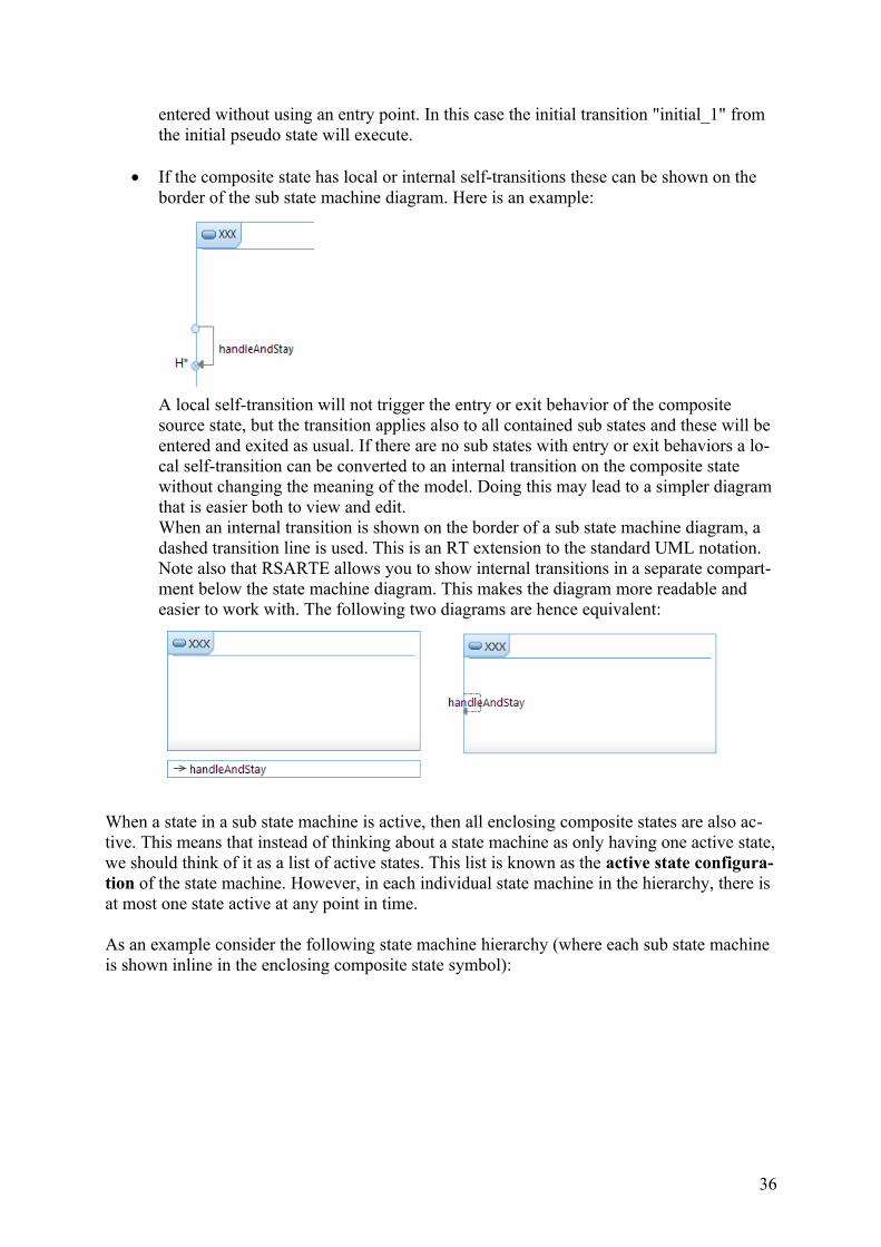
entered without using an entry point. In this case the initial transition "initial_1" from the initial pseudo state will execute.
If the composite state has local or internal self-transitions these can be shown on the border of the sub state machine diagram. Here is an example:
A local self-transition will not trigger the entry or exit behavior of the composite source state, but the transition applies also to all contained sub states and these will be entered and exited as usual. If there are no sub states with entry or exit behaviors a lo-cal self-transition can be converted to an internal transition on the composite state without changing the meaning of the model. Doing this may lead to a simpler diagram that is easier both to view and edit.When an internal transition is shown on the border of a sub state machine diagram, a dashed transition line is used. This is an RT extension to the standard UML notation.Note also that RSARTE allows you to show internal transitions in a separate compart-ment below the state machine diagram. This makes the diagram more readable and easier to work with. The following two diagrams are hence equivalent:
When a state in a sub state machine is active, then all enclosing composite states are also ac-tive. This means that instead of thinking about a state machine as only having one active state,we should think of it as a list of active states. This list is known as the active state configura-tion of the state machine. However, in each individual state machine in the hierarchy, there is at most one state active at any point in time.
As an example consider the following state machine hierarchy (where each sub state machine is shown inline in the enclosing composite state symbol):
36
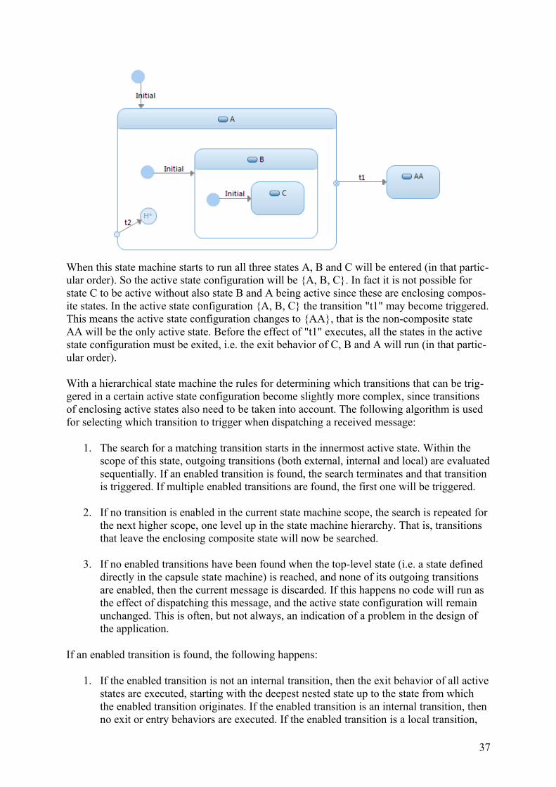
When this state machine starts to run all three states A, B and C will be entered (in that partic-ular order). So the active state configuration will be {A, B, C}. In fact it is not possible for state C to be active without also state B and A being active since these are enclosing compos-ite states. In the active state configuration {A, B, C} the transition "t1" may become triggered.This means the active state configuration changes to {AA}, that is the non-composite state AA will be the only active state. Before the effect of "t1" executes, all the states in the active state configuration must be exited, i.e. the exit behavior of C, B and A will run (in that partic-ular order).
With a hierarchical state machine the rules for determining which transitions that can be trig-gered in a certain active state configuration become slightly more complex, since transitions of enclosing active states also need to be taken into account. The following algorithm is used for selecting which transition to trigger when dispatching a received message:
1. The search for a matching transition starts in the innermost active state. Within the scope of this state, outgoing transitions (both external, internal and local) are evaluatedsequentially. If an enabled transition is found, the search terminates and that transition is triggered. If multiple enabled transitions are found, the first one will be triggered.
2. If no transition is enabled in the current state machine scope, the search is repeated for the next higher scope, one level up in the state machine hierarchy. That is, transitions that leave the enclosing composite state will now be searched.
3. If no enabled transitions have been found when the top-level state (i.e. a state defined directly in the capsule state machine) is reached, and none of its outgoing transitions are enabled, then the current message is discarded. If this happens no code will run as the effect of dispatching this message, and the active state configuration will remain unchanged. This is often, but not always, an indication of a problem in the design of the application.
If an enabled transition is found, the following happens:
1. If the enabled transition is not an internal transition, then the exit behavior of all activestates are executed, starting with the deepest nested state up to the state from which the enabled transition originates. If the enabled transition is an internal transition, then no exit or entry behaviors are executed. If the enabled transition is a local transition,
37
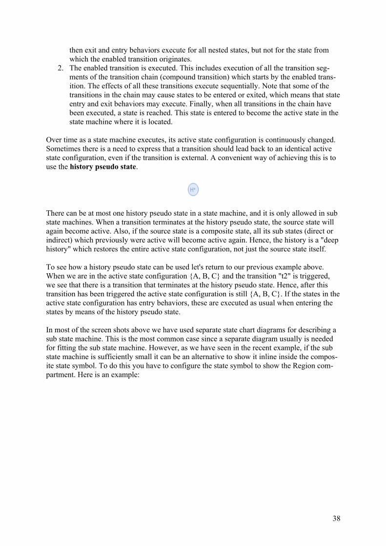
then exit and entry behaviors execute for all nested states, but not for the state from which the enabled transition originates.
2. The enabled transition is executed. This includes execution of all the transition seg-ments of the transition chain (compound transition) which starts by the enabled trans-ition. The effects of all these transitions execute sequentially. Note that some of the transitions in the chain may cause states to be entered or exited, which means that stateentry and exit behaviors may execute. Finally, when all transitions in the chain have been executed, a state is reached. This state is entered to become the active state in the state machine where it is located.
Over time as a state machine executes, its active state configuration is continuously changed. Sometimes there is a need to express that a transition should lead back to an identical active state configuration, even if the transition is external. A convenient way of achieving this is to use the history pseudo state.
There can be at most one history pseudo state in a state machine, and it is only allowed in sub state machines. When a transition terminates at the history pseudo state, the source state will again become active. Also, if the source state is a composite state, all its sub states (direct or indirect) which previously were active will become active again. Hence, the history is a "deephistory" which restores the entire active state configuration, not just the source state itself.
To see how a history pseudo state can be used let's return to our previous example above. When we are in the active state configuration {A, B, C} and the transition "t2" is triggered, we see that there is a transition that terminates at the history pseudo state. Hence, after this transition has been triggered the active state configuration is still {A, B, C}. If the states in theactive state configuration has entry behaviors, these are executed as usual when entering the states by means of the history pseudo state.
In most of the screen shots above we have used separate state chart diagrams for describing a sub state machine. This is the most common case since a separate diagram usually is needed for fitting the sub state machine. However, as we have seen in the recent example, if the sub state machine is sufficiently small it can be an alternative to show it inline inside the compos-ite state symbol. To do this you have to configure the state symbol to show the Region com-partment. Here is an example:
38
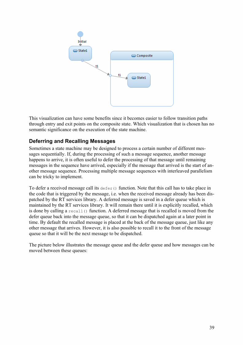
This visualization can have some benefits since it becomes easier to follow transition paths through entry and exit points on the composite state. Which visualization that is chosen has nosemantic significance on the execution of the state machine.
Deferring and Recalling MessagesSometimes a state machine may be designed to process a certain number of different mes-sages sequentially. If, during the processing of such a message sequence, another message happens to arrive, it is often useful to defer the processing of that message until remaining messages in the sequence have arrived, especially if the message that arrived is the start of an-other message sequence. Processing multiple message sequences with interleaved parallelism can be tricky to implement.
To defer a received message call its defer() function. Note that this call has to take place in the code that is triggered by the message, i.e. when the received message already has been dis-patched by the RT services library. A deferred message is saved in a defer queue which is maintained by the RT services library. It will remain there until it is explicitly recalled, which is done by calling a recall() function. A deferred message that is recalled is moved from thedefer queue back into the message queue, so that it can be dispatched again at a later point in time. By default the recalled message is placed at the back of the message queue, just like anyother message that arrives. However, it is also possible to recall it to the front of the message queue so that it will be the next message to be dispatched.
The picture below illustrates the message queue and the defer queue and how messages can bemoved between these queues:
39
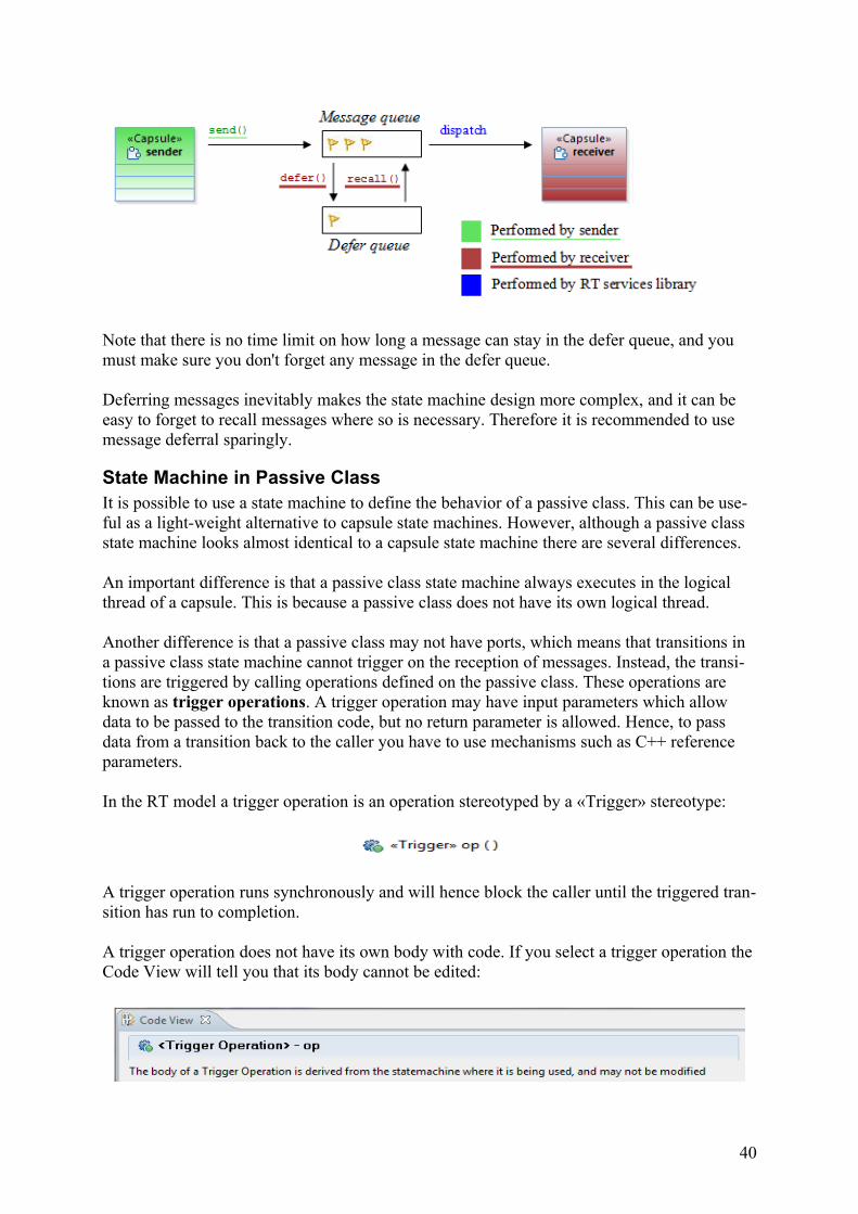
Note that there is no time limit on how long a message can stay in the defer queue, and you must make sure you don't forget any message in the defer queue.
Deferring messages inevitably makes the state machine design more complex, and it can be easy to forget to recall messages where so is necessary. Therefore it is recommended to use message deferral sparingly.
State Machine in Passive ClassIt is possible to use a state machine to define the behavior of a passive class. This can be use-ful as a light-weight alternative to capsule state machines. However, although a passive class state machine looks almost identical to a capsule state machine there are several differences.
An important difference is that a passive class state machine always executes in the logical thread of a capsule. This is because a passive class does not have its own logical thread.
Another difference is that a passive class may not have ports, which means that transitions in a passive class state machine cannot trigger on the reception of messages. Instead, the transi-tions are triggered by calling operations defined on the passive class. These operations are known as trigger operations. A trigger operation may have input parameters which allow data to be passed to the transition code, but no return parameter is allowed. Hence, to pass data from a transition back to the caller you have to use mechanisms such as C++ reference parameters.
In the RT model a trigger operation is an operation stereotyped by a «Trigger» stereotype:
A trigger operation runs synchronously and will hence block the caller until the triggered tran-sition has run to completion.
A trigger operation does not have its own body with code. If you select a trigger operation the Code View will tell you that its body cannot be edited:
40
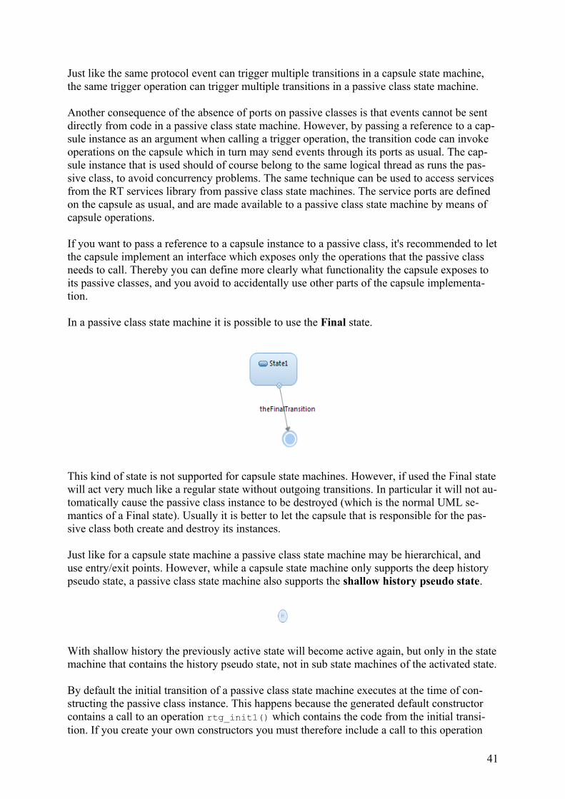
Just like the same protocol event can trigger multiple transitions in a capsule state machine, the same trigger operation can trigger multiple transitions in a passive class state machine.
Another consequence of the absence of ports on passive classes is that events cannot be sent directly from code in a passive class state machine. However, by passing a reference to a cap-sule instance as an argument when calling a trigger operation, the transition code can invoke operations on the capsule which in turn may send events through its ports as usual. The cap-sule instance that is used should of course belong to the same logical thread as runs the pas-sive class, to avoid concurrency problems. The same technique can be used to access services from the RT services library from passive class state machines. The service ports are defined on the capsule as usual, and are made available to a passive class state machine by means of capsule operations.
If you want to pass a reference to a capsule instance to a passive class, it's recommended to letthe capsule implement an interface which exposes only the operations that the passive class needs to call. Thereby you can define more clearly what functionality the capsule exposes to its passive classes, and you avoid to accidentally use other parts of the capsule implementa-tion.
In a passive class state machine it is possible to use the Final state.
This kind of state is not supported for capsule state machines. However, if used the Final statewill act very much like a regular state without outgoing transitions. In particular it will not au-tomatically cause the passive class instance to be destroyed (which is the normal UML se-mantics of a Final state). Usually it is better to let the capsule that is responsible for the pas-sive class both create and destroy its instances.
Just like for a capsule state machine a passive class state machine may be hierarchical, and use entry/exit points. However, while a capsule state machine only supports the deep history pseudo state, a passive class state machine also supports the shallow history pseudo state.
With shallow history the previously active state will become active again, but only in the statemachine that contains the history pseudo state, not in sub state machines of the activated state.
By default the initial transition of a passive class state machine executes at the time of con-structing the passive class instance. This happens because the generated default constructor contains a call to an operation rtg_init1() which contains the code from the initial transi-tion. If you create your own constructors you must therefore include a call to this operation
41
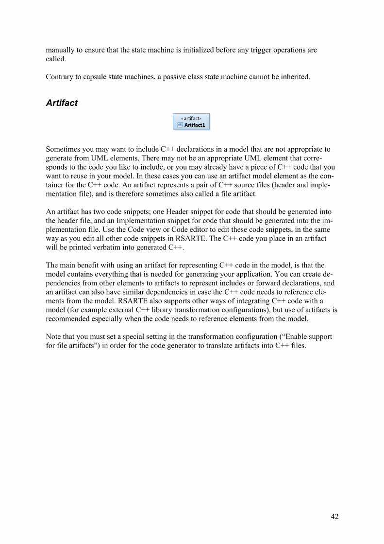
manually to ensure that the state machine is initialized before any trigger operations are called.
Contrary to capsule state machines, a passive class state machine cannot be inherited.
Artifact
Sometimes you may want to include C++ declarations in a model that are not appropriate to generate from UML elements. There may not be an appropriate UML element that corre-sponds to the code you like to include, or you may already have a piece of C++ code that you want to reuse in your model. In these cases you can use an artifact model element as the con-tainer for the C++ code. An artifact represents a pair of C++ source files (header and imple-mentation file), and is therefore sometimes also called a file artifact.
An artifact has two code snippets; one Header snippet for code that should be generated into the header file, and an Implementation snippet for code that should be generated into the im-plementation file. Use the Code view or Code editor to edit these code snippets, in the same way as you edit all other code snippets in RSARTE. The C++ code you place in an artifact will be printed verbatim into generated C++.
The main benefit with using an artifact for representing C++ code in the model, is that the model contains everything that is needed for generating your application. You can create de-pendencies from other elements to artifacts to represent includes or forward declarations, and an artifact can also have similar dependencies in case the C++ code needs to reference ele-ments from the model. RSARTE also supports other ways of integrating C++ code with a model (for example external C++ library transformation configurations), but use of artifacts isrecommended especially when the code needs to reference elements from the model.
Note that you must set a special setting in the transformation configuration (“Enable support for file artifacts”) in order for the code generator to translate artifacts into C++ files.
42
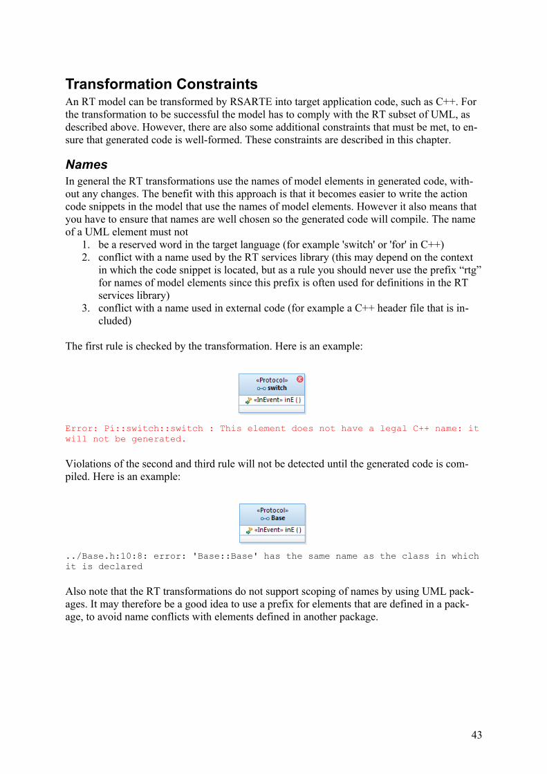
Transformation ConstraintsAn RT model can be transformed by RSARTE into target application code, such as C++. For the transformation to be successful the model has to comply with the RT subset of UML, as described above. However, there are also some additional constraints that must be met, to en-sure that generated code is well-formed. These constraints are described in this chapter.
NamesIn general the RT transformations use the names of model elements in generated code, with-out any changes. The benefit with this approach is that it becomes easier to write the action code snippets in the model that use the names of model elements. However it also means that you have to ensure that names are well chosen so the generated code will compile. The name of a UML element must not
1. be a reserved word in the target language (for example 'switch' or 'for' in C++)2. conflict with a name used by the RT services library (this may depend on the context
in which the code snippet is located, but as a rule you should never use the prefix “rtg”for names of model elements since this prefix is often used for definitions in the RT services library)
3. conflict with a name used in external code (for example a C++ header file that is in-cluded)
The first rule is checked by the transformation. Here is an example:
Error: Pi::switch::switch : This element does not have a legal C++ name: itwill not be generated.
Violations of the second and third rule will not be detected until the generated code is com-piled. Here is an example:
../Base.h:10:8: error: 'Base::Base' has the same name as the class in whichit is declared
Also note that the RT transformations do not support scoping of names by using UML pack-ages. It may therefore be a good idea to use a prefix for elements that are defined in a pack-age, to avoid name conflicts with elements defined in another package.
43
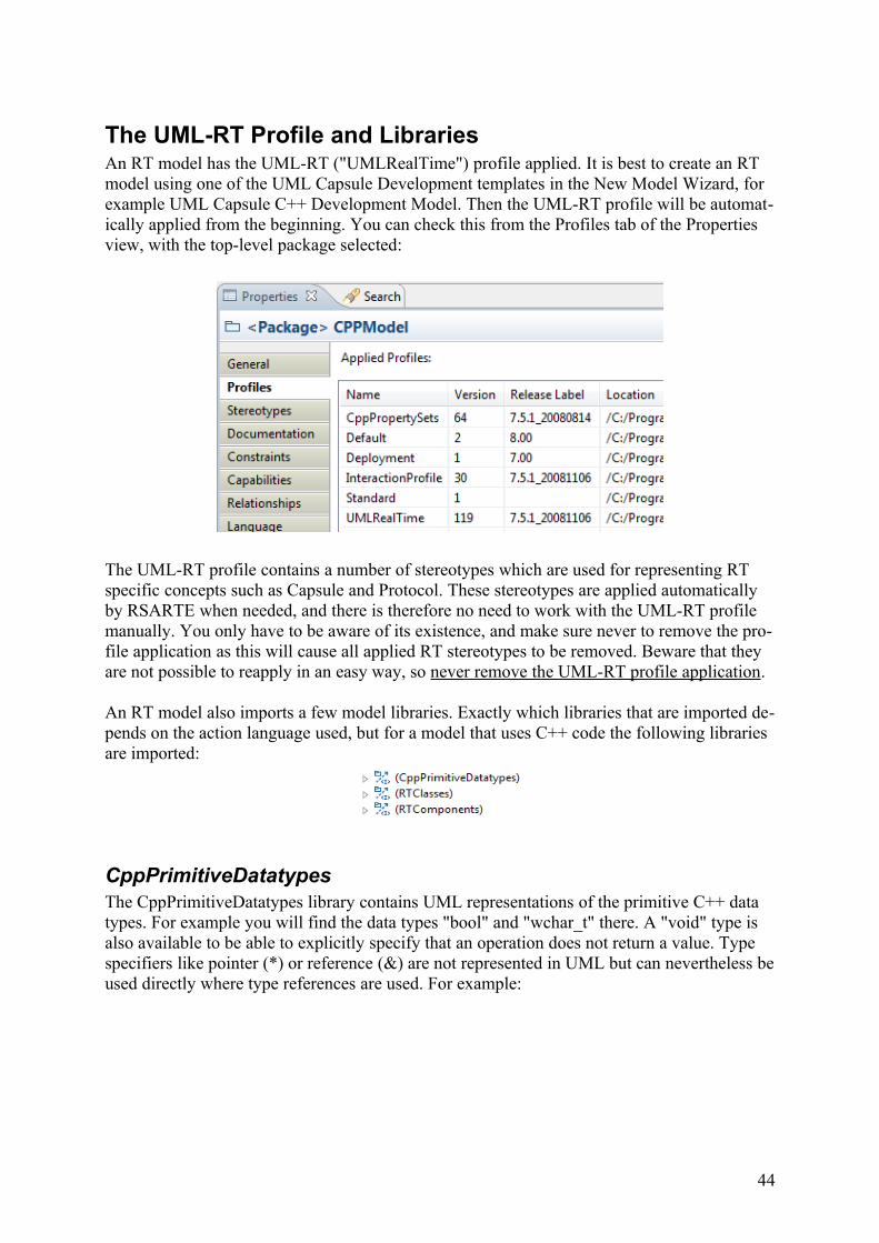
The UML-RT Profile and LibrariesAn RT model has the UML-RT ("UMLRealTime") profile applied. It is best to create an RT model using one of the UML Capsule Development templates in the New Model Wizard, for example UML Capsule C++ Development Model. Then the UML-RT profile will be automat-ically applied from the beginning. You can check this from the Profiles tab of the Properties view, with the top-level package selected:
The UML-RT profile contains a number of stereotypes which are used for representing RT specific concepts such as Capsule and Protocol. These stereotypes are applied automatically by RSARTE when needed, and there is therefore no need to work with the UML-RT profile manually. You only have to be aware of its existence, and make sure never to remove the pro-file application as this will cause all applied RT stereotypes to be removed. Beware that they are not possible to reapply in an easy way, so never remove the UML-RT profile application.
An RT model also imports a few model libraries. Exactly which libraries that are imported de-pends on the action language used, but for a model that uses C++ code the following libraries are imported:
CppPrimitiveDatatypesThe CppPrimitiveDatatypes library contains UML representations of the primitive C++ data types. For example you will find the data types "bool" and "wchar_t" there. A "void" type is also available to be able to explicitly specify that an operation does not return a value. Type specifiers like pointer (*) or reference (&) are not represented in UML but can nevertheless beused directly where type references are used. For example:
44
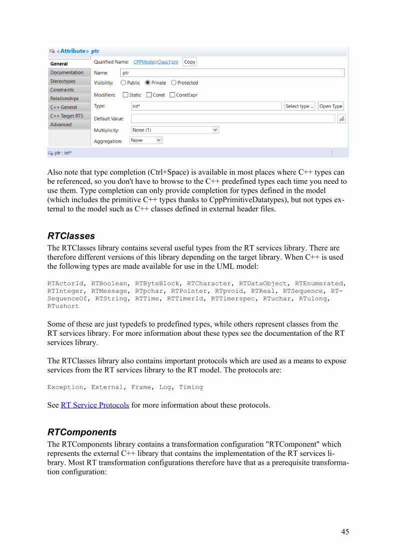
Also note that type completion (Ctrl+Space) is available in most places where C++ types can be referenced, so you don't have to browse to the C++ predefined types each time you need to use them. Type completion can only provide completion for types defined in the model (which includes the primitive C++ types thanks to CppPrimitiveDatatypes), but not types ex-ternal to the model such as C++ classes defined in external header files.
RTClassesThe RTClasses library contains several useful types from the RT services library. There are therefore different versions of this library depending on the target library. When C++ is used the following types are made available for use in the UML model:
RTActorId, RTBoolean, RTByteBlock, RTCharacter, RTDataObject, RTEnumerated,RTInteger, RTMessage, RTpchar, RTPointer, RTpvoid, RTReal, RTSequence, RT-SequenceOf, RTString, RTTime, RTTimerId, RTTimerspec, RTuchar, RTulong, RTushort
Some of these are just typedefs to predefined types, while others represent classes from the RT services library. For more information about these types see the documentation of the RT services library.
The RTClasses library also contains important protocols which are used as a means to expose services from the RT services library to the RT model. The protocols are:
Exception, External, Frame, Log, Timing
See RT Service Protocols for more information about these protocols.
RTComponentsThe RTComponents library contains a transformation configuration "RTComponent" which represents the external C++ library that contains the implementation of the RT services li-brary. Most RT transformation configurations therefore have that as a prerequisite transforma-tion configuration:
45
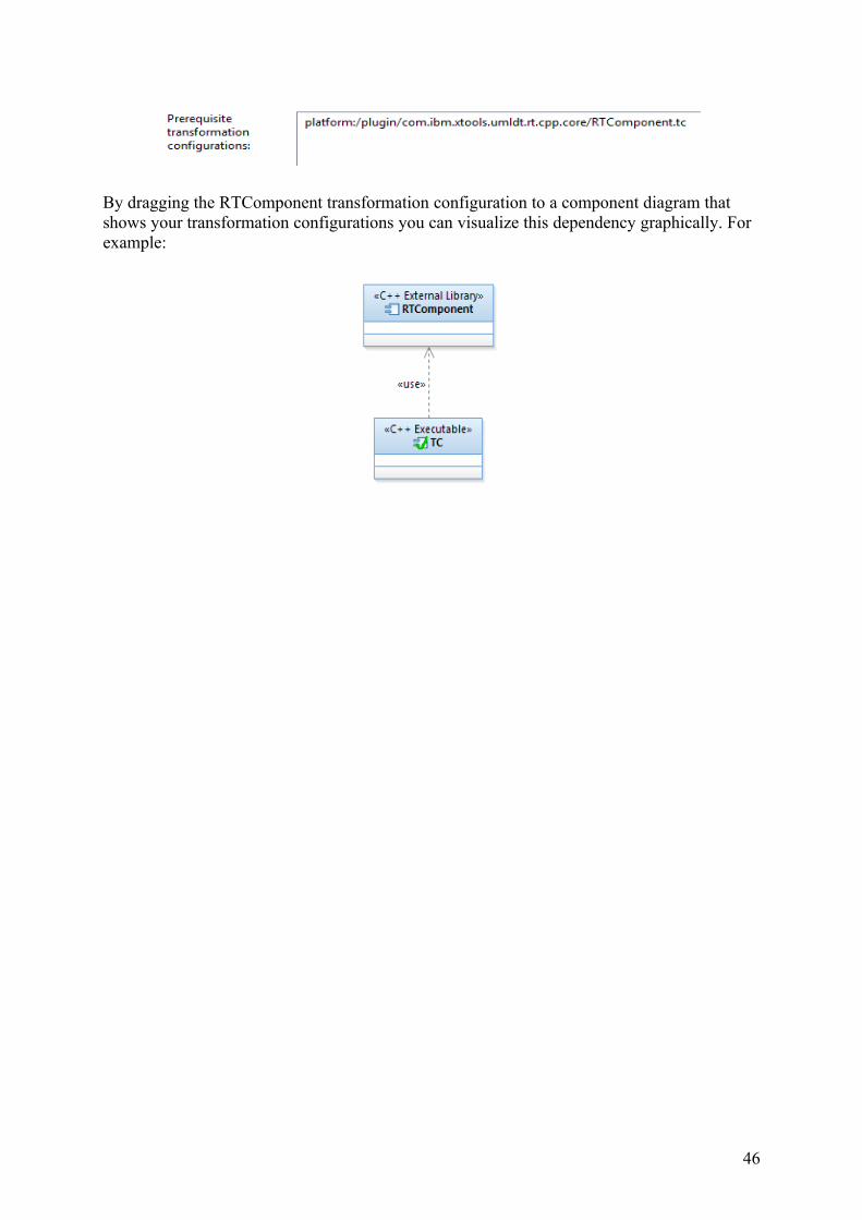
By dragging the RTComponent transformation configuration to a component diagram that shows your transformation configurations you can visualize this dependency graphically. For example:
46