Modeling – Power modeling - SMDPII-VLSI:Special … · Modeling – Power modeling Janakiraman V...
43
Modeling – Power modeling Janakiraman V II year, ME Micro electronics Department of Electrical and Communication Engineering Indian Institute of Science, Bangalore - 560012
Transcript of Modeling – Power modeling - SMDPII-VLSI:Special … · Modeling – Power modeling Janakiraman V...

Modeling – Power modelingJanakiraman V
II year, ME Micro electronicsDepartment of Electrical and Communication Engineering
Indian Institute of Science, Bangalore 560012

Agenda
● Modeling – Need for models● Good models● Components of power in CMOS● Dynamic power model● Short circuit power model● Static power current model ● Simplifying models● Case study● Statistical Modeling

Modeling – Need for models
● Mathematically represent the system● Functional form: output = f(input)● Predict output for given input● Model too complicated?● Simplify models● How do we simplify models?
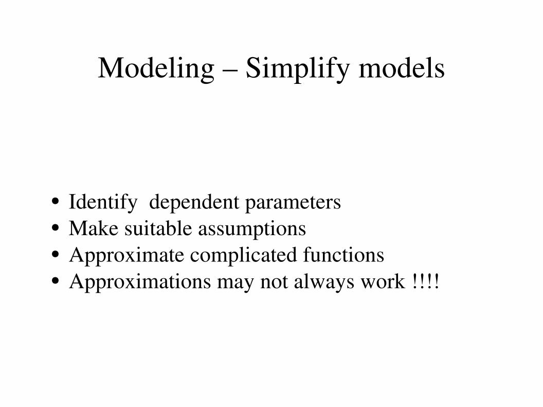
Modeling – Simplify models
● Identify dependent parameters● Make suitable assumptions● Approximate complicated functions● Approximations may not always work !!!!

Modeling – Simplify models
● Empirically fit data● Consider y = f(x), some “complicated function”● Express f(x) as
● How to choose ?
f x =∑n=0
N
an gnx
gnx , N , an

Modeling – Empirical models
● Choice of depends on the application● Taylor series:● Fourier series:● Choice of N depends on accuracy.● Calculating depends on the application● Usually least mean square fit● Coefficients preferably have physical meaning
gnx
gnx =xn
gnx =einx
an

Good models
● Mimics the actual device to the desired accuracy● Simple and easily tractable● Captures the dependence on all parameters● Validate models with actual device● BSIM3 is a good model for the MOSFET

Components of power
● Dynamic power: Switching activity● Short circuit power: Low resistance path from
VDD to GND● Static power: High resistance path from VDD to
GND

Agenda
● Modeling – Need for models● Good models● Dynamic power model● Short circuit power model● Static power model ● Simplifying models● Case study● Statistical Modeling

Dynamic power
● Output switches● Output capacitance (COUT) charges/ discharges● Current from VDD/ COUT dissipates power● Inverter – Best example
● Jan Rabey, Anantha Chandrashekaran and Borivoje Nikolic

Dynamic power model● Assume:
✔ Input has ZERO rise/ fall time✔ Only output capacitance stores energy
● Let output transition from 0 to 1
COUT
iVDD
EVDD=∫0
∞
iV DDt V DD dt
EVDD=COUT V DD2
EC=∫0
∞
iV DDt vout t dt
EC=COUT V DD
2 2
VDD

Dynamic power model
● Energy from supply = EVDD
● Energy stored in COUT = EC
● Energy dissipated = EVDD – EC
● Energy dissipated in PMOS
● Output: 1 to 0 transition● Energy stored EC dissipates● Energy dissipates in NMOS
COUT
iCOUT
VDD
VDD

Dynamic power model
● Frequency of switching = f 0>1
● Total energy per switching cycle = COUTVDD2
● Total Dynamic power PDYN = COUTVDD2f0>1
● Example: 250 nm Process✔ Supply voltage = VDD = 2.5V✔ Average COUT = 15fF (FO4)✔ Average PDYN = 50 uW✔ Clock rate = 500 MHz✔ 1 million gates on chip => Total power = 50W!!!
● Whats wrong?

Dynamic power model
● Not all gates switch at the clock rate● No switching means PDYN = 0● P0>1 = Probability of switching of a gate● PDYN = COUTVDD
2P0>1f = CEFFVDD2f
● Model load capacitance as effective capacitance● Suppose activity factor = 10%● Previous example : PDYN = 5W● Do inputs have Zero Rise/ Fall time?

Agenda
● Modeling – Need for models● Good models ● Dynamic power model● Short circuit power model● Static power model ● Simplifying models● Case study● Statistical Modeling

Short circuit power
● Signals have non zero rise/ fall time● Both PMOS and NMOS conduct● Creates low resistance path from VDD to GND
COUT
iVDD
VDD
vi
vin
ishort
VTH
VDDVTH
IPEAK
tSC
● Jan Rabey, Anantha Chandrashekaran and Borivoje Nikolic

Short circuit power model
● Consider input going from 0 > 1● vin > VTH NMOS starts discharging COUT
● PMOS not turned off as yet
● NMOS & PMOS are ON => SHORT CIRCUIT
E SC=V DD
I PEAK t sc
2V DD
I PEAK t sc
2E SC=V DD I PEAK t sc
PSC=V DD I PEAK t sc f
t sc=V DD−2V TH
V DD
t s

Short circuit power model
● IPEAK determines PSC
● IPEAK strong function of input/ output slew
● IPEAK very low for large COUT
● IPEAK very large for small COUT
● Clearly different from dynamic power

Agenda
● Modeling – Need for models● Good models ● Dynamic power model● Short circuit power● Static power model ● Simplifying models● Case study● Statistical Modeling

Static power
● No switching activity● Only leakage current● High resistance path from VDD to GND● PSTATIC = ISTATIC VDD

Static current models
● Transistor 1 is ON● Transistor 2 is OFF● Current flowing from VDD to GND?
VDDVDD
VDD
Fig 2: VGS = 0Fig 1: VGS = VDD

Static current models – BSIM3
Too complicated!!!!!!!!Do you need such a complicated model?

Static current models Approximations
● BSIM – Single equation for all regions ● Considers all second order effects● Assume:✔ Not a short channel MOSFET ✔ No velocity saturation ✔ No channel length modulation✔ No DIBL✔ No mobility degradation✔ Yes, current is still there!!!!!!!!● Model from basic device physics is ideal!!!!!

Static current models – BSIM Simplified
● Transistor 1 is in saturation (VDS > VGS – VTH)
I DS=0 Cox W V DD−V TH
2
2 L
● Transistor 2 is in cut off: (VGS = 0) Sub threshold leakage current
I DS=I 01−e−V DS
V T eV GS−V TH
nV T −1
Assumptions don't always work!!!!!

Static current models – StacksVDD
Isubth
A
A
B
B C
C

Agenda
● Modeling – Need for models● Good models ● Dynamic power model● Short circuit power● Static power model ● Simplifying models● Case study● Statistical Modeling

Static current models – Stacks● 3 i/p NAND: NMOS Stack, Single PMOS● NMOS Stack is Input dependent● ON transistors – Short circuits● Consider only OFF transistor stack● Have to solve KCL to find IDS
● Accurate subthreshold current expression
I subth=Ae
qnKT
V G−V S−V TH0−' V SV DS1−e
−qV DS
KT
where , A=[0 Cox'
WLeff
KTq
2
e1.8]
● J.P. Halter and F. Najm

Static current models Stacks
● Consider the OFF transistor stack, Vgi = 0● KCL – Equate IDSi and IDSi1
● Calculate VDSi in terms of VDSi1
V DSi=
nKTq 12'
ln 1Ai−1
Ai
1−e−
qKT
V DSi−1
● Similarly calculate VDS2
V DS2=
nKTq 12'
ln 1Ai−1
Ai
eqV DD
nKT

Static current models Stacks
● Use VDSN and Evaluate Isubth
I subth=AN e
qnKT
V DSN1−e
−qV DSN
KT
● To calculate VSi
V Si= ∑
j=i1
N
V DS j

Static current models Circuits
● Circuit – Collection of Gates● Sum of leakage power of each gate
PLEAK=V DD∑j=1
N G
I LEAK i
where , N G=Number of gates of the circuit
● Leakage depends on input combination● Exhaustive simulation ● M inputs => 2M input combinations● Reduce input sample space?

Static current models – Empirical fit
● Choose few dependent parameters● Example: IDS = f(L)● Try out simple expressions IDS = a0L + a1 L
2
● Monte Carlo simulation: Find a0, a1 Training●
Predict IDS for a given L Testing● High error => Model is incorrect● Change the model!!!!

Static current model – Empirical fit
● One such empirical fit in
I OFF=q1 eq2 Lq3 L2
● Use MATLAB least square fit● Verify with test samples● Model fits very well● Does not capture all parameters!!!!!!!!!!
● Ashish Srivastava, Dennis Sylvester and David Blaauw

Agenda
● Modeling – Need for models● Good models ● Dynamic power model● Short circuit power● Static power model ● Simplifying models● Case study● Statistical Modeling

Statistical modeling
● Transistor parameters are random variables● Worst case design Pessimistic● Current is also random● I = f(L, W, VTH, Tox)● E[I] != f(E[L], E[W], E[VTH], E[Tox])● Questions:
● Average current?● Probability that current < IMAX?●
Yield analysis: P({I<IMAX, T<TMAX})● Ashish Srivastava, Dennis Sylvester and David Blaauw

Summary
● Total power is sum of all three components● PTOTAL = PDYN + PSC + PSTATIC
● PDYN and PSC Depends on activity factor● PSTATIC Independent of switching activity● Efficient and accurate models use combination of
analytical and empirical expressions

Questions?

Thank you

References
● J.P. Halter and F. Najm,“A gatelevel leakage power reduction method for ultralowpower CMOS circuits,” Proceedings, IEEE Custom Integrated Circuits Conference, pp. 475478, 1997.
● Digital integrated circuits by Jan Rabey, Anantha Chandrashekaran and Borivoje Nikolic
● Statistical analysis and optimization for VLSI: Timing and Power by Ashish Srivastava, Dennis Sylvester and David Blaauw

Static current models Circuits
● Find a input vector VK: Static power is minimum● Pick a small set of input vectors: N << 2M
● How do you pick {Vi} i= {1, 2, 3... N}● Random choice [2] of Vi
● Prove: Random sequence {Vi} “converges” to VK
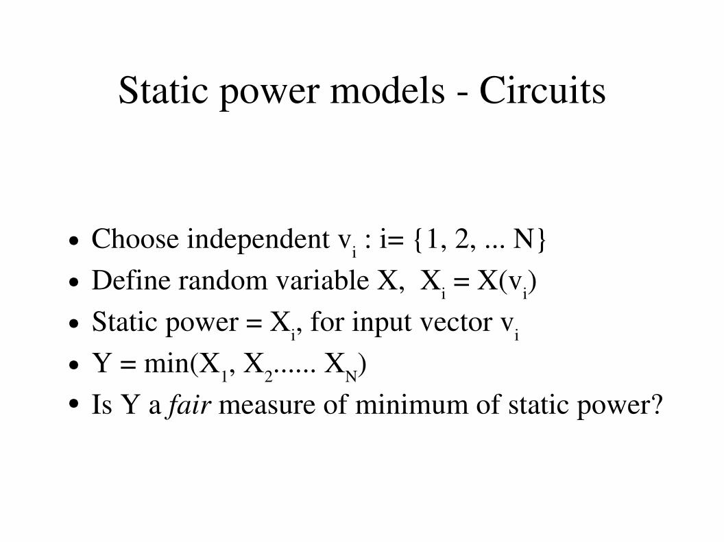
Static power models Circuits
● Choose independent vi : i= {1, 2, ... N}● Define random variable X, Xi = X(vi) ● Static power = Xi, for input vector vi
● Y = min(X1, X2...... XN)● Is Y a fair measure of minimum of static power?

Static power models Circuits
● Cannot say for sure that Y is minimum● Can make a “statistical confidence” statement
P {Y≤I max}≥Confidence that estimated minimum ,Y being less than I max is atleast
if N is large enough. , I max are design parameters.
● This requires knowledge of all input vectors● What other confidence statements can be made?

Static power models Circuits
● Requirement: A “very small” fraction of input vectors have leakage power lesser than Y=y
P {F Y ≤}≥where , F y=P {X≤y}
F y: Fraction of input vectors whose static power is less than yP {F Y ≤}:The fraction is less than
With better than confidence the fraction is less than
n≥ln 1−ln 1−

Static current models Circuits
● Randomly generate at least N vectors● Observe static power for the N vectors● Find the minimum power PMIN
● “Confidently” say there are “very few” vectors which will dissipate lesser power than PMIN
● At least 458 trials to be 99% sure that less than
1% of input vectors dissipate lesser power●
Problem: Not a tight bound