Modeling Pavement Noise with Different Tire Configurations ...
16
Wang and Ding Modeling Pavement Noise with Different Tire Configurations using Coupled 1 FEM/BEM Analysis 2 3 Hao Wang (Corresponding author) 4 Assistant Professor 5 Department of Civil and Environmental Engineering, 6 Rutgers, The State University of New Jersey 7 96 Frelinghuysen Road, Piscataway, NJ, 08854 8 848-445-2874 9 [email protected] 10 11 Yangmin Ding 12 Graduate Research Assistant 13 Department of Civil and Environmental Engineering, 14 Rutgers, The State University of New Jersey 15 97 Frelinghuysen Road, Piscataway, NJ, 08854 16 [email protected] 17 18 19 20 21 22 23 24 25 26 27 28 29 Word Count: 4,500 + 10 figures and tables (2500) = 7000 30 31
Transcript of Modeling Pavement Noise with Different Tire Configurations ...

Wang and Ding
Modeling Pavement Noise with Different Tire Configurations using Coupled 1
FEM/BEM Analysis 2
3
Hao Wang (Corresponding author) 4
Assistant Professor 5
Department of Civil and Environmental Engineering, 6
Rutgers, The State University of New Jersey 7
96 Frelinghuysen Road, Piscataway, NJ, 08854 8
848-445-2874 9
11
Yangmin Ding 12
Graduate Research Assistant 13
Department of Civil and Environmental Engineering, 14
Rutgers, The State University of New Jersey 15
97 Frelinghuysen Road, Piscataway, NJ, 08854 16
18
19
20
21
22
23
24
25
26
27
28
29
Word Count: 4,500 + 10 figures and tables (2500) = 7000 30
31

Wang and Ding
ABSTRACT 1 This paper aims to predict tire-pavement interaction noise using a coupled finite element 2
modeling (FEM) and boundary element modeling (BEM) approach. A dynamic tire-3
pavement interaction model was first developed using the FEM to obtain tire vibration 4
under harmonic excitations. The FEM simulation results provide the tire acceleration 5
histories that serve as the boundary condition for predicting the exterior acoustic field of 6
tire using the BEM. The developed FEM/BEM model was used to study the impact of 7
dual tires and wide-base tires on pavement noise. Two radial truck tires (275/80R22.5 8
and 445/50R22.5) were modeled and the tire models were validated with tire deflections 9
and contact stresses at the tire-pavement interface. The predicted contact stresses show 10
different non-uniform distribution patterns between the dual-tire assembly and the wide-11
base 445 tire. Results indicate that the wide-base 445 tire was quieter than the dual tires 12
and the differences in A-weighted sound pressure levels were observed up to 8.6 decibels 13
(dB). The results illustrate the potential of using the developed model to capture the 14
influence of tire types or tire dimensions on tire-pavement interaction noise. 15
16
17
18

Wang and Ding
INTRODUCTION 1 In recent years, the trucking industry has developed innovations of tire technology for 2
purposes of improving the efficiency of vehicle operations and fuel consumption while 3
minimizing tire wear. An increased interest in the use of wide-base single tires as an 4
alternative to conventional dual-tire assemblies has occurred parallel to the recent interest 5
as an innovative tire technology. Historically, dual-tire assemblies have been used to 6
provide the largest footprint to adequately distribute the axle load onto the pavement 7
surface. However, compared to conventional dual-tire assembly, wide-base tires has the 8
potential to offer several benefits, including improved fuel efficiency, increased hauling 9
capacity, reduced wheel cost, and superior ride and comfort (1). 10
The effects of wide-base tires on the road infrastructure is receiving considerable 11
attention and eliciting widespread interest in pavement researchers, particularly since the 12
introduction of new generation of wide-base tires (wide-base 445 and 455) in 2000s. The 13
impact of the new generation of wide-base tires on pavement damage was firstly 14
investigated in 2000. A comprehensive study was conducted to compare the pavement 15
responses under wide-base tires and the dual-tire assembly on the heavily instrumented 16
Virginia Smart Road. A number of studies were conducted to investigate the pavement 17
damage mechanisms induced by different tire configurations using theoretical modeling 18
and field instrumentations. These studies concluded that the new wide-base 445 or 455 19
tire could cause greater or less pavement damage potential than the dual-tire assembly, 20
depending on the pavement structure and failure mechanism (2-6). 21
The aforementioned studies focus on the impact of wide-base tires on pavement 22
damage. However, researches on the impact of wide-base tires on environment, 23
especially the influence on tire-pavement noise is quite limited. Noise, defined as 24
unwanted or excessive sound, has become one of the greatest sources of nuisance and 25
environmental exposures in the United States (7). While noise emanates from different 26
sources, traffic noise is perhaps the most pervasive and difficult source to avoid (8). In 27
1981, the U.S. Environmental Protection Agency (EPA) estimated that approximately 28
100 million people (about 50% of the population) in the United States had annual 29
exposures to traffic noise that were high enough to threaten the health (9). 30
Traditionally, traffic noise is related with exhaust and engine noise of vehicles. With 31
the development of automobile technology, the emission and propagation noise from 32
such sources are greatly controlled. Instead, the tire-pavement interaction noise becomes 33
dominant. As a major component of the vibrating source of the tire-pavement noise, the 34
tire plays a significant role in noise control (10). The literature survey shows that most 35
researchers consider the effect of tire dimensions on tire-road noise via the use of large-36
scale field or laboratory tests (11). These test methods consume considerable manpower, 37
materials and financial resources. The testing results are susceptible to the interference 38
from a variety of factors, such as environmental factors, traffic conditions, etc. Hence, it 39
is desired to develop a numerical simulation method for evaluating the impact of new 40
generation wide-base tire on tire-pavement noise, as an important means of developing 41
wide-base tire. 42
43
OBJECTIVE AND SCOPE 44
This study explores the application of a modeling approach to predict tire-pavement noise 45
level with different tire configurations. A coupled BEM/FEM analysis approach was 46
Wang and Ding
developed for prediction of tire-pavement interaction noise. Initially, a radial truck tire 1
was first built using the FEM and the surface accelerations under harmonic excitations 2
were obtained from the modal analysis. Then the solutions for the radiation sound fields 3
caused by the tire vibration were solved using the BEM analysis. The tire model was 4
validated with tire deflection and contact stresses at the tire-pavement interface. The 5
FEM/BEM model was used to predict the sound pressure level generated by two truck 6
tire configurations (275/80R22.5 and 445/50R22.5) on the porous asphalt concrete (PAC). 7
Numerical predictions were compared with existing experimental observations from 8
literature and showed consistent trends. 9
10
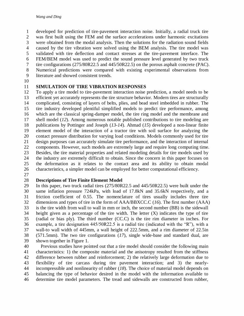
SIMULATION OF TIRE VIBRATION RESPONSES 11 To apply a tire model to tire-pavement interaction noise prediction, a model needs to be 12
efficient yet accurately represents the tire structure behavior. Modern tires are structurally 13
complicated, consisting of layers of belts, plies, and bead steel imbedded in rubber. The 14
tire industry developed plentiful simplified models to predict tire performance, among 15
which are the classical spring-damper model, the tire ring model and the membrane and 16
shell model (12). Among numerous notable published contributions to tire modeling are 17
publications by Pottinger and Joseph (13-14). Ahmad (15) developed a non-linear finite 18
element model of the interaction of a tractor tire with soil surface for analyzing the 19
contact pressure distribution for varying load conditions. Models commonly used for tire 20
design purposes can accurately simulate tire performance, and the interaction of internal 21
components. However, such models are extremely large and require long computing time. 22
Besides, the tire material properties and related modeling details for tire models used by 23
the industry are extremely difficult to obtain. Since the concern in this paper focuses on 24
the deformation as it relates to the contact area and its ability to obtain modal 25
characteristics, a simpler model can be employed for better computational efficiency. 26
27
Descriptions of Tire Finite Element Model 28
In this paper, two truck radial tires (275/80R22.5 and 445/50R22.5) were built under the 29
same inflation pressure 724kPa, with load of 17.8kN and 35.6kN respectively, and a 30
friction coefficient of 0.55. The nomenclature of tires usually includes three tire 31
dimensions and types of tire in the form of AAA/BBXCC.C (16). The first number (AAA) 32
is the tire width from wall to wall in mm or inch, the second number (BB) is the sidewall 33
height given as a percentage of the tire width. The letter (X) indicates the type of tire 34
(radial or bias ply). The third number (CC.C) is the tire rim diameter in inches. For 35
example, a tire designation 445/50R22.5 is a radial tire (indicated with the “R”), with a 36
wall-to wall width of 445mm, a wall height of 222.5mm, and a rim diameter of 22.5in 37
(571.5mm). The two tire configurations (17), single wide-base and standard dual, are 38
shown together in Figure 1. 39
Previous studies have pointed out that a tire model should consider the following main 40
characteristics: 1) the composite material and the anisotropy resulted from the stiffness 41
difference between rubber and reinforcement; 2) the relatively large deformation due to 42
flexibility of tire carcass during tire pavement interaction; and 3) the nearly-43
incompressible and nonlinearity of rubber (18). The choice of material model depends on 44
balancing the type of behavior desired in the model with the information available to 45
determine tire model parameters. The tread and sidewalls are constructed from rubber, 46

Wang and Ding
and the belts and carcass are made of fiber-reinforced rubber composites. Both the rubber 1
and fiber reinforcement are modeled as linear elastic material. Generally, the tire 2
simulation consists of mounting the tire on the rim, followed by inflating it, lowering the 3
tire onto a non-deformable surface, and applying various loading conditions. 4
5
6 FIGURE 1. Wide-base single (445/50R22.5) and on tire of dual-tire assemblies 7
(275/80R22.5). 8
9
The simulation of FE tire model in this study includes three steps. In the first step, an 10
internal inflation pressure is applied on the axisymmetric tire model. The second step of 11
the simulation is generation of a full three-dimensional tire model by using the symmetric 12
results transfer and symmetric model generation (19). In the last step the static deformed 13
shape of the pressurized tire under a vertical load was modeled. The road surface is 14
modelled as analytical rigid body. Two-dimensional tire mesh and three-dimensional tire 15
mesh are shown in Figure 2. 16
The contact between the tire and pavement surface consists of two components: one 17
normal to the surfaces and one tangential to the surfaces. The treatment of the normal 18
contact condition is to enforce impenetrability in the normal direction using the penalty 19
method or Lagrange multipliers method. However, for the tangential interaction between 20
two contacting surfaces, the typical Coulomb friction law is used. This model assumes 21
the resistance to movement is proportional to the normal stress at an interface. In this case, 22
the interface may resist movement up to a certain level; then the two contacting surfaces 23
at the interface start to slide relative to each another. If the relative motion occurs, the 24
frictional stress remains constant and the stress magnitude is equal to the normal stress at 25
the interface multiplied by the friction coefficient. 26
27

Wang and Ding
1 FIGURE 2. Tire finite element meshes (a) Two-dimensional 275 tire mesh; 2
(b) Three-dimensional 275 tire mesh (c);Two-dimensional 445 tire mesh; (d) 3
Three-dimensional 445 tire mesh. 4
5
Validation of Tire Finite Element Model 6 Tire deflection is an important measure of the tire stiffness in response to the vertical load. 7
In this paper, tire load deflection curves and measured contact stresses curves from 8
experimental measurements are used to calibrate the tire model (20, 21). Good 9
agreements were achieved between the calculated tire deflections and measurements 10
under different load and pressure conditions, as illustrated in Figure 3. A mesh sensitivity 11
analysis with a series of gradually finer finite element meshes was conducted to refine the 12
mesh in the contact area. By comparing the predicted contact stresses for each mesh, the 13
final mesh was selected until the changes in the result was smaller than 5%. 14
15
(a) 16
0
5
10
15
20
25
30
0 10 20 30 40 50
Load
on
Tir
e (
kN
)
Deflection (mm)
Measurement at 828kPa
Prediction at 828kPa
Measurement at 552kPa
Prediction at 552kPa

Wang and Ding
1 (b) 2
FIGURE 3. Comparisons between measured and predicted deflections for (a) dual 3
275 tire and (b) wide-base 445 tire. 4 5
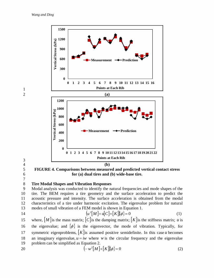
The predicted vertical contact stresses at the tire-pavement contact zone were 6
compared to the experimental measurements provided by the tire manufacturer. As 7
shown in Figure 4, the tire model captured the non-uniform distribution of vertical 8
contact stresses under each individual tire rib. As the tire is pressed against a flat surface, 9
the tread rubber is compressed in the flattened contact patch and the sidewall of the tire is 10
in tension. The bending stress in the sidewall causes the non-uniform distribution of 11
vertical contact stresses in the contact patch, particularly at the edge of the contact patch. 12
The maximum vertical stress under the center rib was found to be 1.4-1.6 times the 13
inflation pressure owing to the non-uniform contact stress distribution. 14
The results indicate that the wide-base tire has relatively more uniform vertical stress 15
distribution along the tire width compared to the dual-tire assembly, which is consistent 16
with the measurements reported in the authors’ previous work (4). It is noted that the 17
non-uniform contact stresses have significant influence on pavement responses at the 18
near-surface, as indicated in the previous work by the authors (5, 6). Based on the good 19
agreement in the measured tire deflections and contact stresses, the proposed tire model is 20
assumed to be reasonable for tire-pavement interaction analysis. 21
22
0
10
20
30
40
50
0 20 40 60
Loa
d o
n T
ire (
kN
)
Deflection (mm)
Measurement at 828kPa
Prediction at 828kPa
Measurement at 552kPa
Prediction at 552kPa
Wang and Ding
1
(a) 2
3 (b) 4
FIGURE 4. Comparisons between measured and predicted vertical contact stress 5
for (a) dual tires and (b) wide-base tire. 6
7
Tire Modal Shapes and Vibration Responses 8
Modal analysis was conducted to identify the natural frequencies and mode shapes of the 9
tire. The BEM requires a tire geometry and the surface acceleration to predict the 10
acoustic pressure and intensity. The surface acceleration is obtained from the modal 11
characteristics of a tire under harmonic excitation. The eigenvalue problem for natural 12
modes of small vibration of a FEM model is shown in Equation 1. 13
02 KCuMu (1) 14
where, M is the mass matrix; C is the damping matrix; K is the stiffness matrix; u is 15
the eigenvalue; and is the eigenvector, the mode of vibration. Typically, for 16
symmetric eigenproblems, K is assumed positive semidefinite. In this case u becomes 17
an imaginary eigenvalue, iwu where w is the circular frequency and the eigenvalue 18
problem can be simplified as Equation 2. 19
02 KMw (2) 20
0
300
600
900
1200
1500
0 1 2 3 4 5 6 7 8 9 10 11 12 13 14 15 16
Verti
cal S
tress
(k
Pa)
Points at Each Rib
Measurement Prediction
0
200
400
600
800
1000
1200
0 1 2 3 4 5 6 7 8 9 10 11 12 13 14 15 16 17 18 19 20 21 22
Verti
ca
l S
tress
(k
Pa
)
Points at Each Rib
Measurement Prediction

Wang and Ding
Two approaches can be used for solving the symmetrized eigenproblems: subspace 1
iteration method and Lanczos method. Both methods use the Householder and Q-R 2
algorithm for the reduced eigenproblem. The basic idea of the subspace iteration method 3
is simultaneous inverse power iteration. In this method, a small set of base vectors is 4
generated, which defines a “subspace”. Then the “subspace” is transformed, by iteration, 5
into the space containing the lowest few eigenvectors of the overall system (22). The 6
Lanczos procedure consists of a set of Lanczos “runs”, in each of which a set of steps is 7
performed. The Lanczos eigensolver is a powerful tool for extraction of the extreme 8
eigenvalues and the corresponding eigenvectors of a sparse symmetric generalized 9
eigenproblem (23). This paper employs Lanczos method for tire modal analysis. There 10
were a total of 20 structural vibration modes identified from the FEM modal analysis in 11
the frequency range between 10-800 Hz. Figure 5 illustrates the first four radial modes of 12
tire vibration, respectively, for one tire in dual-tire assembly and the wide-base 445 tire. 13
14
15 FIGURE 5. Finite element modal analysis results. 16
17
Steady state linear dynamic analysis predicts the linear response of a structure 18
subjected to continuous harmonic excitation. The set of eigenmodes extracted in the 19
previous eigenfrequency step were used to calculate the steady state solution as a 20
function of the frequency of the applied excitation. The structural dynamics equation for 21
steady-state response under a harmonic excitation is shown in Equation 3. 22
FUMwCiwK 2 (3) 23
where, U is the nodal displacement vector of the structure; and K is the load vector of 24
the external excitation. 25
The acceleration response obtained in the FE analysis was used as a boundary 26
condition for a BEM analysis of the transmitted noise field. Generally, tire-pavement 27
noise can be described as two mechanisms: the mechanical vibrations of the tire, and the 28
aerodynamic phenomenon (10). In this study, only the vibrations noise is taken into 29
consideration. Since the frequency spectrum characteristic of noise is not affected by the 30
amplitude of the harmonic excitation, the acceleration responses of the tire was calculated 31
with harmonic point loads of unit magnitude in the frequency range from 10 to 800Hz. 32

Wang and Ding
The point load is applied to the analytical rigid surface through its reference node. Figure 1
6 illustrates the acceleration frequency response of a node from the tire sidewall. 2
3
4 FIGURE 6. Example of tire acceleration spectrum at 37.24Hz for one tire in dual-5
tire assembly 6
7
TIRE-PAVEMENT NOISE PREDICTION 8
9
Basic Theory of BEM 10
The mathematical formulation and practical application of the BEM have been discussed 11
in details in previous publications, such as Brebbia and Walker (24), Telles and Wrobel 12
(25). The application of the BEM to wave problems can be found in the work of Shaw 13
and Copley (26, 27). 14
As a numerical method used to solve a wide variety of boundary value problems, there 15
are two approaches in the boundary element formulation: the direct boundary element 16
method (DBEM) and the indirect boundary element method (IBEM). In the DBEM the 17
physical variables, such as acoustical pressure and acoustical velocity are solved directly 18
from the discretized surface integral equations. By comparison, in the IBEM the problem 19
is formed in accordance with a source density function, and the distribution of fictitious 20
sources is solved on the boundary. In this study, only the DBEM was used. 21
The governing partial differential equation for linear acoustics in the frequency domain 22
is the Helmholtz equation, Equation 4. 23
022 pk (4) 24
where, 2 is the Laplace operator and p is the acoustic pressure. cwk is the wave 25
number. w is the angular frequency and c is the speed of sound. The boundary condition 26
for the vibro-acoustic problems is given in Equation 5. 27
nwvinp (5) 28
where, n is the normal vector pointing outside from the acoustic volume; 1i is the 29
imaginary unit; is the acoustic fluid density and nv is the normal velocity. From the 30
theory of Green’s functions, Equation 6 can be recast into the Helmholtz integral for an 31
exterior boudnary value problem (28): 32
0
100
200
300
0 100 200 300 400 500 600 700 800 900
Accele
ra
tion
(m
/s2)
Frequency (Hz)

Wang and Ding
dn
Gp
n
pGPp (6) 1
where, r
eGikr
4
is the singular fundamental solution, and r is the distance between 2
the field point. 3
4
Boundary Element Modeling of Tire Pavement System 5
The acceleration response obtained in the FE analysis as described in the previous section 6
is used as a boundary condition for a BEM analysis of the transmitted noise field. To 7
solve the acoustic problem, the DBEM formulation was used in this study. For a given 8
acceleration field on the tire BEM surface, an acoustic BEM direct frequency response 9
analysis calculates pressure and normal acceleration values at all the boundary nodes and 10
field points. The outer surface elements of the tire were selected to constitute the 11
boundary element. In order to avoid sound leakage, additional elements were added to the 12
rim. In the dual-tire model, a symmetric total reflection panel is built to simulate the other 13
tire. The distance between the symmetric panel and tire is 310 mm (dual spacing). The 14
boundary of the BE model is exactly the same as the FE model of the tire, in this way the 15
acceleration response of the tire could be transferred directly to the BE model. 16
17
Tire-Pavement Noise under Different Tire Configurations 18
In this study, field points to calculate sound pressure are chosen to be identical to the 19
measurement location in the CPX method. Instead of measuring sound intensity level 20
from a phase-matched pair of microphones (as the OBSI method does), CPX measures 21
levels via sound pressure from a single microphone. According to the ISO/DIS 11819-2, 22
the microphone positions in the CPX method are illustrated in Figure 7. The five 23
microphones in CPX method are modeled with corresponding five field points in BEM. 24
Table 1 presents the exact positions of the field points in BEM. The coordinates of the 25
origin is (0, 0, 0) located at the tire center. 26
27
TABLE 1 Field point coordinates for dual-tires and wide-base tire 28
Field Point X Coordinate (mm) Y Coordinate (mm) Z Coordinate (mm)
Dual Tires
1 0 337 265
2 200 337 265
3 -200 337 265
4 650 0 165
5 -650 0 165
Wide-base Tire
1*
2*
3*
4*
5*
0
200
-200
650
-650
422
422
422
0
0
435
435
435
335
335
29

Wang and Ding
1 FIGURE 7. Microphone positions in the CPX method. 2
3
The road surface in the BEM was modeled as porous asphalt concrete (PAC) surfaces. 4
PAC consists primarily of gap-graded aggregates held together by a polymer modified 5
binder to form a matrix with inter-connecting voids. Unlike conventional asphalt 6
pavements, PAC typically possesses 15-25 % void volume (11). In effect this increase in 7
porosity means that the PAC acts as porous sound-absorbent materials and greatly 8
absorbs the sound, converting it into a small amount of friction energy, thereby reducing 9
noise. To theoretically model the sound propagation through a porous absorber, it is 10
necessary to have frequency dependent sound velocity, and frequency dependent mass 11
density which characterize the acoustic properties of the absorbent acoustic medium. In 12
our previous work, a theoretical model has been developed to analyze the effects of pore 13
structure parameters (pore radius, pore length and porosity) on the acoustic absorption 14
coefficient of PAC. The porous material parameters with pore radius 6mm, pore length 15
4cm and porosity 25% used in this study are obtained from our previous work (29). 16
Figures 8 (a) and (b) illustrate the frequency responses of the sound pressure level at 17
the field points, respectively, for the dual-tire assemble and the wide-base tire. In the 18
figures, there are several dominant peaks of sound pressure responses at different 19
frequencies. The simulated tire-pavement noise peak is higher than the present 20
experimental data and the trend of the noise level curves have more fluctuations 21
compared to the measured data from existing literatures (30-31). That may be partly 22
attributed to the effects of the simple harmonic excitation and factors related to tire 23
parameters like tire material, tire dimension. Other factors like temperatures and the 24
rolling condition of tire could also affect the noise level. 25
It was observed from the figures that the wide-base tire induces smaller sound pressure 26
level at the low frequency range (10-200Hz). While within the frequency range higher 27
than 200Hz, the wide-base tire causes the same noise level compared with the 28
conventional dual tires. This probably because the acceleration response difference 29
between these two tires as discussed in the above section. 30

Wang and Ding
1
2 (a) 3
4 (b) 5
FIGURE 8. Sound pressure at selected field points for (a) dual-tire assembly and 6
(b) wide-base tire. 7
8
The analysis in Figure 8 simulates sound pressure level at different frequency bands9
piL . The overall sound pressure level pL is calculated as 10
10
10
1
10*log 10 pi
NL
p
i
L
(7) 11
TABLE 2 Comparison of overall noise level at field points 12
FP1 FP2 FP3 FP4 FP5
Tire Type (dBA) (dBA) (dBA) (dBA) (dBA)
Dual-tire assemblies 125.5 125.1 125.0 126.4 126.4
Wide-base tire 118.2 117.5 117.0 116.7 117.8
The overall noise levels for these two kinds of tires at field points are presented in 13
Table 2. Concerning the impact of wide-base tire and dual tires on overall tire pavement 14
interaction noise level, it has been shown here that the wide-base tires is quieter than the 15
0
20
40
60
80
100
120
0 200 400 600 800 1000
Nois
e L
evel
(dB
A)
Frequency (Hz)
FP1 FP2 FP3 FP4 FP5
0
20
40
60
80
100
120
0 200 400 600 800 1000
Nois
e L
evel
(dB
A)
Frequency (Hz)
FP1 FP2 FP3 FP4 FP5

Wang and Ding
dual tires. Differences in A-weighted sound pressure levels up to 8.6 dB(A) are observed. 1
One possible reason why dual-tires seem to emit higher noise levels may be that the 2
number of tires is higher. As literature (11) showing 16 wheels of a typical tractor-3
semitrailer combination give 6 dB higher noise level than a reference four-wheel vehicle. 4
Further investigation is needed to validate the finding using field noise measurements for 5
different truck tires. 6
7
CONCLUSIONS 8
In this study, a coupled FEM and BEM model was developed to predict tire-pavement 9
interaction noise. The results show that the sound field caused by tire vibration and 10
absorption properties of pavement surface can be predicted with appropriate selection of 11
the excitation spectrum and acoustic parameters of pavement surface using the developed 12
approach. The FEM/BEM model was used to predict the noise generated by the two truck 13
radial tires. The results show that in the low frequency range lower than 200Hz, the dual-14
tire assembly is noisier than the wide-base tire. However, within the frequency range 15
higher than 200Hz, the wide-base tire causes the similar noise level compared to the 16
conventional dual tires. Concerning the impact of tire configuration on the overall tire-17
pavement interaction noise, it was found that the new generations of wide-base tire is 18
quieter than the dual tires. Differences in A-weighted sound pressure levels were 19
observed up to 8.6 dB(A). The results illustrate the potential of using the developed 20
model to capture the influence of tire types or tire dimensions on tire-pavement 21
interaction noise. 22
23
REFERENCES 24
1. Al-Qadi, I. L., and M. A. Elseifi. New Generation of Wide-Base Tires: Impact on 25
Trucking Operations, Environment, and Pavements. In Transportation Research 26
Record: Journal of the Transportation Research Board, No. 2008, Transportation 27
Research Board of the National Academies, Washington, D.C., 2007, pp. 100-109. 28
2. Al-Qadi, I. L., A. Loulizi, I. Janajreh and T.E. Freeman. Pavement Response to Dual 29
Tires and New Wide-Base Tires at Same Tire Pressure. In Transportation Research 30
Record: Journal of the Transportation Research Board, No. 1806, Transportation 31
Research Board of the National Academies, Washington, D.C., 2002, pp. 38-47. 32
3. Greene, J., U. Toros, S. Kim, T. Byron., and B. Choubane. (2010) Impact of Wide-33
Base Tires on Pavement Damage. In Transportation Research Record: Journal of the 34
Transportation Research Board, No. 2115, Transportation Research Board of the 35
National Academies, Washington, D.C., 2010, pp. 82-90. 36
4. Wang, H. and I.L. Al-Qadi, Impact Quantification of Wide-base Tire Loading on 37
Secondary Road Flexible Pavements, Journal of Transportation Engineering, Vol. 38
137. No.9, ASCE, 2011, pp. 630-639. 39
5. Al-Qadi, I.L., and H. Wang, Impact of Wide-Base Tires on Pavements: Results from 40
Instrumentation Measurements and Modeling Analysis, In Transportation Research 41
Record: Journal of the Transportation Research Board, No. 2304, TRB, 2012, pp. 42
169-176. 43
6. Wang, H. and I.L. Al-Qadi, Combined Effect of Moving Wheel Loading and Three-44
Dimensional Contact Stresses on Perpetual Pavement Responses, In Transportation 45

Wang and Ding
Research Record: Journal of the Transportation Research Board, No. 2095, TRB, 1
2009, pp. 53-61. 2
7. García A. Environmental Urban Noise, Wentworth Insitute of Technology Press, 3
Boston, 2001. 4
8. Mark, F. Highway Traffic Noise in the United States-Problem and Response, 5
Publication FHWA-HEP-06-020. FHWA, U.S. Department of Transportation, 2006. 6
9. Simpson, M., and R. Bruce. Noise in America: Extent of the Noise Problem, Report 7
550/9-81-101. Washington, DC, Environmental Protection Agency, 1981. 8
10. Hanson, D. I., R. S. James, and C. NeSmith. Tire/Pavement Noise Study. Report 04-9
02. Auburn, National Center for Asphalt Technology, 2004. 10
11. Sandberg U., J. A. Easement. Tire/Road Noise Reference Book. Informex, Kisa, 2002. 11
12. Knothe, K. Advanced Contact Mechanics-Road and Rail, Vehicle System Dynamics, 12
Vol. 35, 2001, pp. 361-407. 13
13. Pottinger, M. G. Three-Dimensional Contact Patch Stress Field of Solid and 14
Pneumatic Tires. Tire Science and Technology, Vol. 20, 1992, pp. 3-32. 15
14. Padovan, J. On Standing Waves in" Tires". Tire Science and Technology, Vol. 5, 16
1997, pp. 83-101. 17
15. Ahmad M. Modelling of Pneumatic Tractor Tire Interaction with Multi-Layered Soil. 18
Biosystems Engineering, Vol. 104, 2009, pp. 191-198. 19
16. Wang, H. Analysis of Tire-Pavement Interaction and Pavement Responses Using a 20
Decoupled Modeling Approach. Ph.D. Dissertation, University of Illinois at Urbana-21
Champaign, Illinois, USA, 2011. 22
17. Angela L. P., H. David and E. B. William. Mechanistic Comparison of Wide-base 23
Single Vs. Standard Dual Tire Configurations. NCAT Report 05-03, 2005. 24
18. Wong, J.Y. Theory of Ground Vehicles, John Wiley & Sons, Inc., New York, 1993. 25
19. ABAQUS Analysis User’s Manual. Abaqus, Version 6.10-EF, 2010. 26
20. Hernandez, J.A., and A. Gamez, and I.L. Al-Qadi. Introducing an Analytical 27
Approach for Predicting 3D Tire-Pavement Contact Load. In Transportation 28
Research Record: Journal of the Transportation Research Board, No.14-2201, 2014. 29
21. Wang, H., I. L. Al-Qadi, and I. Stanciulescu. Simulation of Tire-Pavement Interaction 30
for Predicting Contact Stresses at Static and Various Rolling Conditions. 31
International Journal of Pavement Engineering, Vol. 12, 2012, pp. 310-321. 32
22. Ramaswami, S. Towards Optimal Solution Techniques for Large Eigenproblems in 33
Structural Mechanics, Ph.D. Thesis, MIT, 1979. 34
23. Parlett, B.N. Toward a Black Box Lanczos Program. Computer Physics 35
Communications, Vol. 53, 1989, pp. 169-179. 36
24. Brebbia, C.A., S. Walker. Boundary Element Techniques in Engineering. Newness-37
Butterworths, 1980. 38
25. Brebbia, C. A., J. Telles, J, and L., Wroble. Boundary Element Techniques: Theory 39
and Applications in Engineering, Springer-Verlag, 1984. 40
26. Shaw, R. P. Boundary Integral Equation Methods Applied to Wave Problems. 41
Applied Science Publishers, Vol. 1, 1979, pp. 121-153. 42
27. Copley, L. G. Integral Equation Method for Radiation from Vibrating Bodies. The 43
Journal of the Acoustical Society of America, Vol. 41, 1967, pp. 807-816. 44
28. Wu, T.W. Boundary element acoustics: Fundamentals and computer codes. WIT 45
Press, United Kingdom, 2000. 46

Wang and Ding
29. Wang, H., Ding, Y. M., and Liao, G. Y. Modeling and Optimization of Acoustic 1
Absorption for Porous Asphalt Concrete. Journal of Engineering Mechanics, 2014 2
(Under Review). 3
30. McDaniel, R. S. Field Evaluation of Porous Friction Course for Noise Control. 4
Presented at 84th Annual Meeting of the Transportation Research Board, Washington, 5
D.C., 2005. 6
31. McDaniel, R. S. Field Evaluation of Porous Asphalt Pavement. Final Report, SQDH 7
2004-3. North Central Superpave Center, West Lafayette, Ind., 2004. 8