Modeling of Terrestrial Channels in System C Copyright, 1996 © Dale Carnegie & Associates, Inc. by...
27
Modeling of Modeling of Terrestrial Channels Terrestrial Channels in System C in System C Copyright, 1996 © Dale Carnegie & Associates, Inc. by Jiangtao Yi Philips Research Lab
-
Upload
stephen-sharp -
Category
Documents
-
view
213 -
download
0
Transcript of Modeling of Terrestrial Channels in System C Copyright, 1996 © Dale Carnegie & Associates, Inc. by...

Modeling of Terrestrial Modeling of Terrestrial Channels in System CChannels in System C
Copyright, 1996 © Dale Carnegie & Associates, Inc.
by Jiangtao YiPhilips Research Lab

IntroductionIntroduction
The first step in Multi_Standard Channel Decoder project is to build a system specification at several level of abstraction in System C. Channel Modeling is part of this work.

MSCD: SpecificationMSCD: Specification
•System Spec.
• Hardware Architecture Spec.
• Hardware Design Spec.
• IC: MSCD

My ScopeMy Scope
Channel Tx
• Simulation (System Spec.)
Rx ADC

Top level Requirement for ChannelTop level Requirement for Channel
• AWGNAWGN
• MultipathMultipath• RayleighRayleigh
• RiceRice
• DopplerDoppler
• Inter-channel interferenceInter-channel interference
• Phase noisePhase noise

Software ArchitectureSoftware Architecture
Multipath fading
Parameter Selector
AWGN Tx
ADC
Rx
• System C

Advantages using System C Advantages using System C ModuleModule
• Scalable and Flexible.Scalable and Flexible.
• Can be simulated with different Tx/Rx.Can be simulated with different Tx/Rx.
• Build-in Analysis can be provided.Build-in Analysis can be provided.
• User Extensible.User Extensible.

Impulse Response Model of Impulse Response Model of Multi-path Channel Multi-path Channel
Baseband ModelBaseband Model
hb(t, ) c(t) r(t)

• x(t) = Re{c(t)exp(jct)}
• y(t) = Re{r(t)exp(jct)}
BandPass ModelBandPass Model
h(t, ) = 2*Re {hb(t,)exp(jct)}
x(t)
y(t)

• In Multi-path Channel
h(t, ) = k {hbk(t, ) exp(jct)}
hbk(t, ) = Ak(t, ) (t- k(t)) exp(j*k)
• k is phase shift for each path
• Ak (t, ) is Rayleigh&Doppler
fading factor (complex)

Bandpass Model for One PathBandpass Model for One Path
x(t)
A(t)
delay
exp(jc k +j k))
Re{ }
y(t) x(t- k)
• y(t) = conv(x(t), Re{hk(t)})
= x(t- k) * Re{ A(t) exp (j(c k +k))}

Rayleigh Fading(Baseband)Rayleigh Fading(Baseband)
Gaussian Spec
Doppler filter
IFFT
Gaussian Spec
Doppler filter
IFFT *j
interpolating
A(t)
• Clarks Model

Interpolating filterInterpolating filter
• Cubic Spline interpolating side band 50 dB down
• linear interpolating side band 20 dB down


Channel TestingChannel Testing
• This Model is tested with a model of US DTV transimitter(8-VSB).
• Wc = 1.31 M Hz.
• Fs = 21.52 M Hz.
• Doppler_sampling_rate = 215.2 Hz

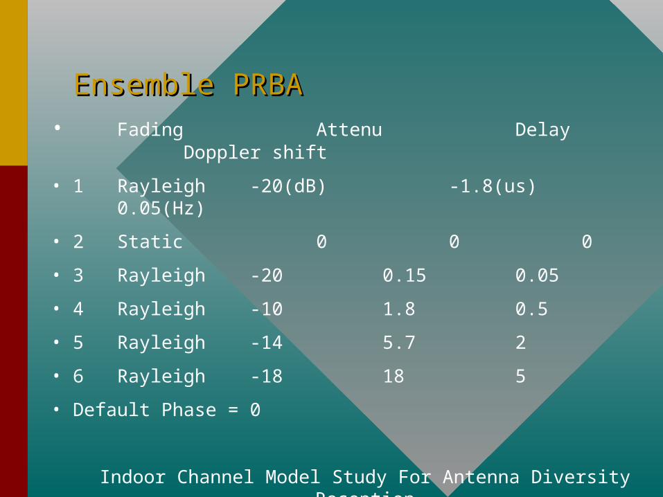
Ensemble PRBAEnsemble PRBA• Fading Attenu Delay Doppler shift
• 1 Rayleigh -20(dB) -1.8(us)0.05(Hz)
• 2 Static 0 0 0
• 3 Rayleigh -20 0.15 0.05
• 4 Rayleigh -10 1.8 0.5
• 5 Rayleigh -14 5.7 2
• 6 Rayleigh -18 18 5
• Default Phase = 0
Indoor Channel Model Study For Antenna Diversity Reception
Xuemei Ouyang


Ensemble PRBFEnsemble PRBF
• Fading Attenu Delay Doppler shift
• 1 Rayleigh -18(dB) -1.8(us)0.05(Hz)
• 2 Static 0 0 0
• 3 Rayleigh -3 0.0465 0.05
• Default Phase = 0
Indoor Channel Model Study For Antenna Diversity Reception
Xuemei Ouyang


Harbor ChannelHarbor Channel
• Fading Attenu Delay phase Doppler shift
• 1 Static -3(dB) 1.2546(us) 0 0(Hz)
• 2 Static -18 1.4405 0 0
• 3 Static -8 3.0204 180 0
• 4 Static -11.6 3.4387 0 0
• 5 Static -17 6.0409 180 0
• 6 Static -26 7.5743 0 0
• 7 Static -20 9.8513 180 0
(take the coefficiency > -40 dB)


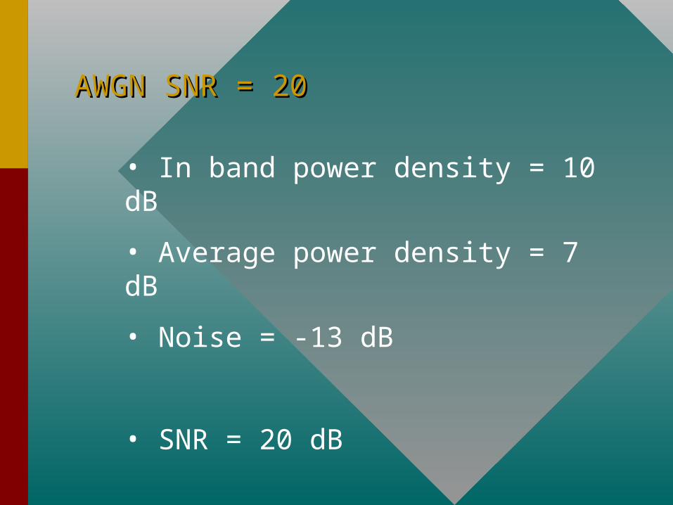
AWGN SNR = 20AWGN SNR = 20
• In band power density = 10 dB
• Average power density = 7 dB
• Noise = -13 dB
• SNR = 20 dB

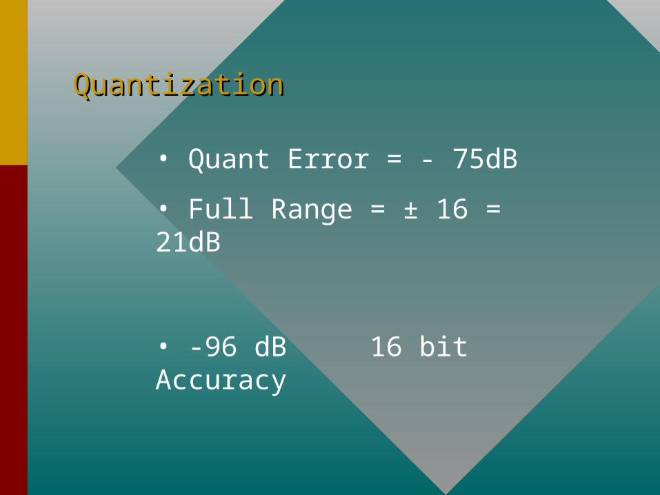
QuantizationQuantization
• Quant Error = - 75dB
• Full Range = ± 16 = 21dB
• -96 dB 16 bit Accuracy
SummarySummary
• The terrestrial channel model is done on Rayleigh fading path, AWGN, and fixed 16 bit Quantizor.
• Further work lies in Lognormal fading path, configurable quantizor and tunner; also more ensemble need to be tested.