Modeling of Radiation Heat Transfer in Liquid Rocket
28
Modeling of Radiation Heat Transfer in Liquid Rocket Engines M.H. Naraghi Department of Mechanical Engineering, Manhattan College, Riverdale, NY 10471 S. Dunn and D. Coats SEA Inc., 1802 North Carson Street, Suite 200 Carson City, NV 89701
Transcript of Modeling of Radiation Heat Transfer in Liquid Rocket
Modeling of Radiation Heat Transfer in Liquid Rocket Engines
M.H. NaraghiDepartment of Mechanical Engineering, Manhattan College,
Riverdale, NY 10471
S. Dunn and D. CoatsSEA Inc., 1802 North Carson Street, Suite 200 Carson City, NV
89701

Motivation• Design of cooling circuits of regenaratively cooled rocket
engines both a good physical insight on the workings of the engine and a method of calculating the effects of design changes on the heat transfer via conjugated convection/conduction/radiation and cooling requirements of LRE’s
• Conjugated convection and conduction models for liquid rocket engines are well established (e.g., TDK-RTE model)
• Combustion gases in liquid rocket engines consists of gases at very high temperatures (up to 7000R) with radiatively participating gases, e.g. water vapor, CO, CO2 and soot.

Previous Works• Hammad, K.J., and Naraghi, M.H.N., “Exchange
Factor Model for Radiative Heat Transfer Analysis in Rocket Engines,” AIAA Journal of Thermophysics and Heat Transfer, Vol. 5, No. 3, pp. 327-334, 1991.
• Liu, J., and Tiwari, S.N., “Radiative Heat Transfer Effects in Chemically Reacting Nozzle Flows,” AIAA Journal of Thermophysics and Heat Transfer, Vol. 10, No. 3, 1996.
• Badinand, T. and Fransson, T.H., “Radiative Heat Transfer in Film Cooled LH/LO Rocket Engine Thrust Chamber”, AIAA Journal of Thermophysics and Heat Transfer, Vol. 17, No. 2, pp. 29-34, 2003.
• Wang, Tee-See, “Multidimensional Unstructured-Grid Liquid Rocket Engine Nozzle Performance and Heat Transfer Analysis,”AIAA paper 2004-4016 presented at the 40th AIAA/ASME/SAE/ASEE Joint Propulsion Conference and Exhibit July 11-14, 2004, Fort Lauderdale, Florida.
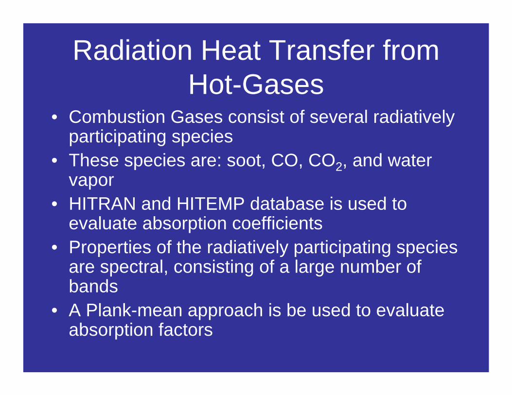
Radiation Heat Transfer from Hot-Gases
• Combustion Gases consist of several radiativelyparticipating species
• These species are: soot, CO, CO2, and water vapor
• HITRAN and HITEMP database is used to evaluate absorption coefficients
• Properties of the radiatively participating species are spectral, consisting of a large number of bands
• A Plank-mean approach is be used to evaluate absorption factors
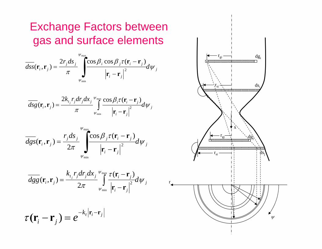
Exchange Factors betweengas and surface elements
rsi
r
x
rgi dgi
dsi
rgj
rsi
dgj
dsj
ψ
j
ji
jijijjji d
dsrdss ψ
τββπ
ψ
ψ∫ −
−=
max
min
2
)(coscos2),(
rr
rrrr
j
ji
jiijjjtji d
dxdrrkdsg j ψ
τβπ
ψ
ψ∫
−
−=
max
min
2
)(cos2),(
rr
rrrr
j
ji
jijjjji d
dsrdgs ψ
τβπ
ψ
ψ∫ −
−=
max
min
2
)(cos2
),(rr
rrrr
j
ji
jijjjtji d
dxdrrkdgg j ψ
τπ
ψ
ψ∫
−
−=
max
min
2
)(2
),(rr
rrrr
jitkji e rrr(r −−=− )τ

Radiative Nodal Points
Nodal points in radial direction
Nodal points in axial direction, the same as stations

Total Exchange FactorsAccount for wall reflection and gas scattering
[ ]{ }[ ] [ ]{ }αdgsWdssIWdsgdssρWdgsWdggIWdsgdssIDSS ggsgg
1
00
11
00
−−−−+−+−= ωωωω
[ ] [ ]{ }[ ] αdgsWdggIWdsgdssρWIdgsWdggIDGS ggsg
-11
00
1
0
−−−+−−= ωωω
Wall heat flux at station n
nsjgnj
nm
jjgjsnj
mn
jjsnr EESDGwESDSwq
rr
,,1
,,
2
1,, −+= ∑∑
⋅
=
+
=
4nn ss TE εσ= 4
0 )1(4jlj gtg TKE σω−=
This model is built in the TDK’s radiation module (RAD2005)
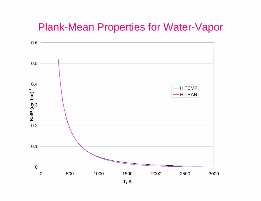
Plank-Mean Properties for Water-Vapor
0
0.1
0.2
0.3
0.4
0.5
0.6
0 500 1000 1500 2000 2500 3000
T, K
Ka/
P (c
m b
ar)-1 HITEMP
HITRAN

Plank-Mean Properties for CO2
0
0.05
0.1
0.15
0.2
0.25
0.3
0.35
0.4
0 500 1000 1500 2000 2500 3000T, K
ka/P
(cm
bar
)-1
HITEMPHITRAN
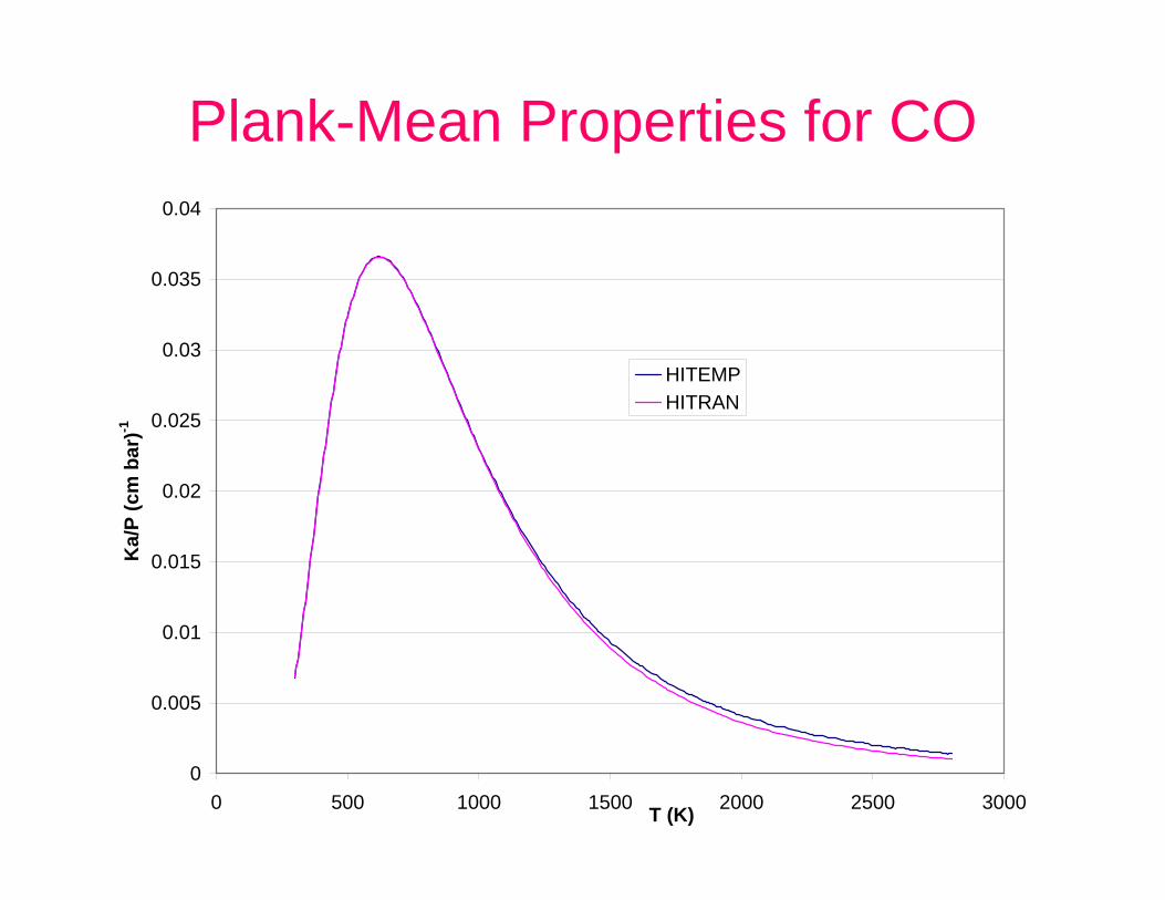
Plank-Mean Properties for CO
0
0.005
0.01
0.015
0.02
0.025
0.03
0.035
0.04
0 500 1000 1500 2000 2500 3000T (K)
Ka/
P (c
m b
ar)-1
HITEMPHITRAN

Absorption Coefficient of Soot
20 /72.3 CTCfk va =
222220 4)2(36
knknnkC++−
=π
Where fv is volume fraction of soot
C2=1.4388 cm K, n and k are real and imaginary part of index ofrefraction
When engines running with rich hydrocarbon fuels soot is presentin the combustion gases. As of today little is known about the nature of the production, Destruction, shape and size distribution. An approximate valueof soot absorption coefficient can be obtained via:

Computer Model
The properties and computational models (RAD2005) discussed were incorporated in the TDK-RTE.
Naraghi, M.H.N., Dunn, S., and Coats, D., “A Model for Design and Analysis of Regeneratively Cooled Rocket Engines,” AIAA paper 2005-3852, present at the Joint Propulsion Conference, Fort Lauderdale, July 2004.

Results for a LH2-LO2 Engine(SSME)
The specifications of this engine are:Chamber pressure 3027 psiaO/F 6.0Contraction ratio 3.0Expansion ratio 77.5Throat diameter 10.3 inchesPropellant LH2-LO2Coolant LH2Total coolant flow rate 29.06 lb/sCoolant inlet temperature 95RCoolant inlet stagnation pressure 6452 psiaNumber of cooling channels 430

Effects of radiation on the wall heat flux of the SSME
20
30
40
50
60
70
80
90
100
110
-15 -10 -5 0 5 10Axial Position (in)
Wal
l Hea
t Flu
x (B
tu/in
2 s)
No RadiationWith Radiation, HITRANWith Radiation, HITEMP

Effects of radiation on the wall temperature of the SSME
600
800
1000
1200
1400
1600
-15 -10 -5 0 5 10Axial Position (in)
Wal
l Sur
face
Tem
pera
ture
(R)
No RadiationWith Radiation HITRANWith Radiation HITEMP

Effects of radiation on the coolant stagnation temperature of the SSME
100
200
300
400
500
600
700
-15 -10 -5 0 5 10Axial Position (in)
Coo
lant
Sta
gnat
ion
Tem
pera
ture
(R)
No radiationWith Radiation, HITRANWith Radiation, HITEMP

Effects of radiation on coolant stagnation pressure of SSME
4000
4500
5000
5500
6000
6500
7000
-15 -10 -5 0 5 10
Axial Position (in)
Coo
lant
Sta
gnat
ion
Pres
sure
(psi
)
With Radiation, HITEMPWith Radiation, HITRANNo Radiation

Results for a RP1-LO2 Engine
The specifications of this engine are:Chamber pressure 2,000 psiO/F (mixture ratio) 1.8Contraction ratio 3.4Expansion ratio 7.20Throat diameter 2.6 inchPropellant RP1-LO2Coolant LO2Total coolant flow rate 32.893 lb/sCoolant inlet temperature 160°RCoolant inlet pressure 3,000 psiNumber of cooling channels 100 Throat region channel aspect ratio 2.5
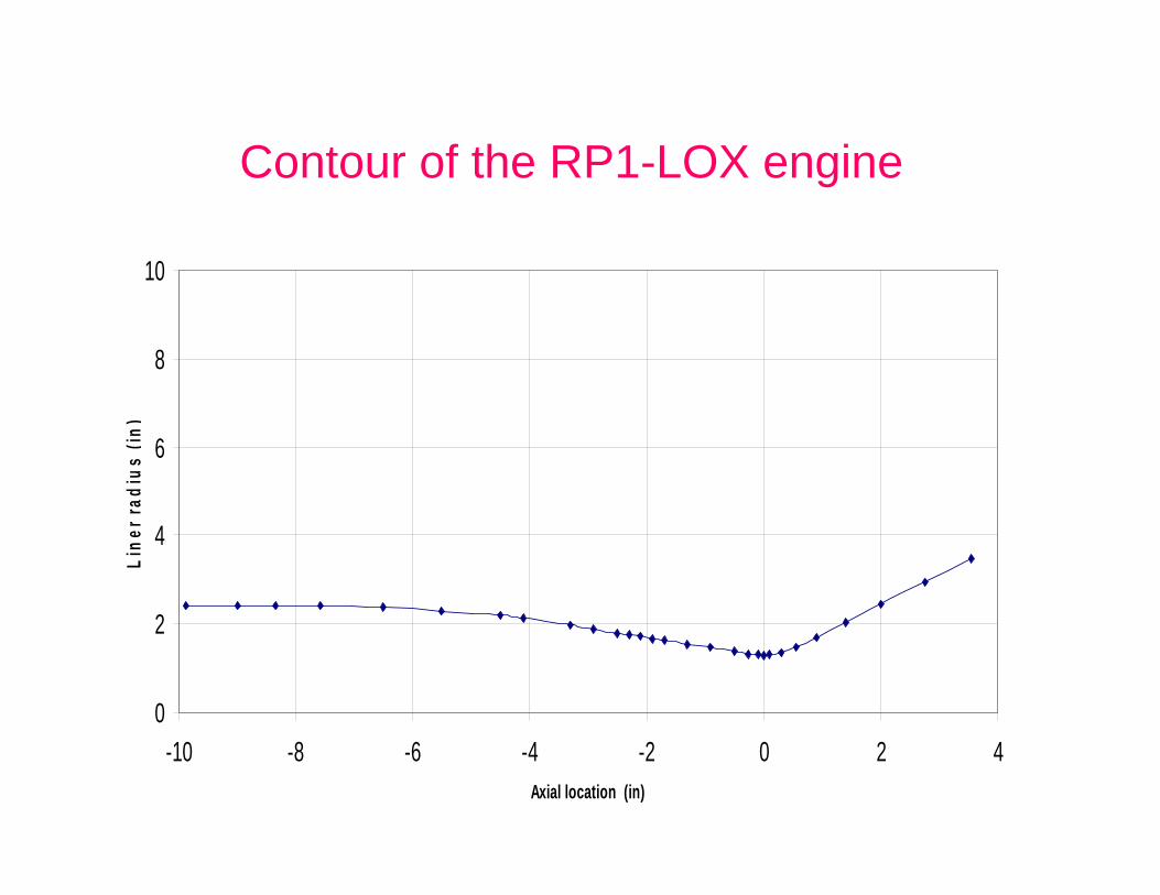
Contour of the RP1-LOX engine
0
2
4
6
8
10
-10 -8 -6 -4 -2 0 2 4Axial location (in)
Line
r rad
ius
(in)

Effects of radiation on the wall heat flux of the RP1-LOX engine
0
5
10
15
20
25
30
35
40
45
50
-10 -5 0 5Axial location (in)
QW
, BTU
/s in
2
No radiationWith Radiation HITEMP

Effects of radiation on the wall temperature of the RP1-LOX
engine
200
400
600
800
1000
1200
1400
-10 -5 0 5
Axial location (in)
TW (R
)
No Radition
With Radition HITEMP

Effects of radiation on the coolant temperature of the RP1-LOX
engine
150
200
250
300
350
400
450
-10 -5 0 5Axial location, in
Coo
lant
tem
pera
ture
, R
No RadiationWith Rdiation HITEMP

Effects of radiation on the coolant stagnation pressure of the RP1-LOX
engine
2300
2400
2500
2600
2700
2800
2900
3000
-10 -5 0 5
Axial location, in
Coo
lant
sta
gnat
ion
pres
sure
, psi
No radiationWith radiation

Effects of radiation on the coolant Mach number of the RP1-LOX engine
0
0.05
0.1
0.15
0.2
0.25
0.3
0.35
-10 -5 0 5Axial location, in
Coo
lant
Mac
h nu
mbe
r
No radiationWith Radiation, HITEMP

Concluding Remarks
• The effects of gas and surface radiation on the wall temperature, coolant pressure, temperature and Mach number were studied
• The results presented demonstrate that although the increase in heat flux due to radiation is small, it can have a significant effect on the wall temperature and coolant flow characteristics

Concluding Remarks
• For a LH2/LO2 engine it is shown that the radiation has a small effect on the wall temperature of the diverging section of the nozzle
• the radiation results in a substantial increase in the wall temperature of the thrust chamber and converging section of the nozzle, such that the local peak temperature is the same order of magnitude as the throat temperature

Concluding Remarks
• For the RP1/LO2 engine, radiative heat transfer resulted in a 30% increase in wall temperature. Additionally, it significantly increased the coolant pressure drop and Mach number
• neglecting radiation during the design phase may result in a faulty cooling system
Availability of the Radiation CodeRAD2005
• The model presented is incorporated in a program (RAD2005) which can be linked to TDK and RTE
• TDK from Software Engineering Associates, Inc. (seainc.com)
• RTE from Tara Technologies, LLC (tara-technologies.com)