Modeling Of Pulse Width Modulation Control Strategy For Single Phase To Three Phase ...€¦ ·...
13
DOI : 10.23883/IJRTER.2017.3380.HNFP5 8 Modeling Of Pulse Width Modulation Control Strategy For Single Phase To Three Phase Conversion System For Industrial Applications RASHMIKA.DHOOMALA 1 , NOORULLAH.MOHAMMAD 2 1 M.Tech Student, 2 Assistant Professor 12 Department of EEE Vaagdevi College of Engineering, Warangal, Telangana India. Abstract: Single-phase to three-phase power conversion using power electronics converters is a well- known technology, when the configurations and control strategies already accomplished in the technical study are considered. This paper presents single-phase to three-phase with dc-link converters with parallel rectifier and series inverter for reduction in the input current and reduction of the output voltage processed by the rectifier circuit and inverter circuit respectively. In this paper we proposed better solution for single phase to three phase drive system by employing 2 parallel single phase rectifier stages, a 3-phase inverter stage. Parallel converters can be used to improve the power capability, reliability, efficiency and redundancy. An isolation transformer is not used for the reduction of circulating currents among different converter stages. It is an important objective in the system design. The complete comparison between the comprehensive model of proposed converter and standard configurations will be presented in this work. Simulation of this model will be carried out by using MATLAB/ Simulink. Keywords: Power conversion, power electronics converters, parallel converter, pulse width modulation, three phase ac motor drive. I. INTRODUCTION In the past, single-phase to three-phase conversion systems were made possible by the connection of passive elements (capacitors and reactors) with auto transformer converters. Such kind of system presents well-known disadvantages and limitations. In present days, power electronics with silicon power diodes and thyristors are just emerging. So power electronics plays an important role day by day. In the power distribution systems, the single-phase source has been considered as an alternative for rural or remote areas, due to its lower cost feature, especially when compared with the three-phase solution. In huge countries like Brazil, the single-phase source is quite common due to the large area to be covered. On the other hand, a load connected in a three-phase arrangement presents some advantages when compared to single-phase loads. This is especially true in three-phase motor systems with variable-speed drives due to their constant torque characteristic. In this scenario, there is a need for single-phase to three-phase power conversion systems. The direct solutions for the single-phase to three phase.power converters are presented in Fig. 1. Fig. 1(b) shows a solution for single-phase to three- phase power conversion, in which all variables (e.g., input power factor and dc-link voltage) at input– output converter sides can be controlled, as observed in Fig. 2(b). On the other hand, the configuration presented in Fig. 1(a) represents a cheaper solution but without any control of the input current and dc- link voltage, as observed in Fig. 2(a).
Transcript of Modeling Of Pulse Width Modulation Control Strategy For Single Phase To Three Phase ...€¦ ·...

DOI : 10.23883/IJRTER.2017.3380.HNFP5 8
Modeling Of Pulse Width Modulation Control Strategy For Single Phase
To Three Phase Conversion System For Industrial Applications
RASHMIKA.DHOOMALA1, NOORULLAH.MOHAMMAD2
1M.Tech Student, 2Assistant Professor 12Department of EEE Vaagdevi College of Engineering, Warangal, Telangana India.
Abstract: Single-phase to three-phase power conversion using power electronics converters is a well-known technology, when the configurations and control strategies already accomplished in the technical
study are considered. This paper presents single-phase to three-phase with dc-link converters with
parallel rectifier and series inverter for reduction in the input current and reduction of the output voltage
processed by the rectifier circuit and inverter circuit respectively. In this paper we proposed better
solution for single phase to three phase drive system by employing 2 parallel single phase rectifier
stages, a 3-phase inverter stage. Parallel converters can be used to improve the power capability,
reliability, efficiency and redundancy. An isolation transformer is not used for the reduction of
circulating currents among different converter stages. It is an important objective in the system design.
The complete comparison between the comprehensive model of proposed converter and standard
configurations will be presented in this work. Simulation of this model will be carried out by using
MATLAB/ Simulink.
Keywords: Power conversion, power electronics converters, parallel converter, pulse width modulation,
three phase ac motor drive.
I. INTRODUCTION
In the past, single-phase to three-phase conversion systems were made possible by the connection of
passive elements (capacitors and reactors) with auto transformer converters. Such kind of system
presents well-known disadvantages and limitations. In present days, power electronics with silicon
power diodes and thyristors are just emerging. So power electronics plays an important role day by day.
In the power distribution systems, the single-phase source has been considered as an alternative for rural
or remote areas, due to its lower cost feature, especially when compared with the three-phase solution.
In huge countries like Brazil, the single-phase source is quite common due to the large area to be
covered. On the other hand, a load connected in a three-phase arrangement presents some advantages
when compared to single-phase loads. This is especially true in three-phase motor systems with
variable-speed drives due to their constant torque characteristic. In this scenario, there is a need for
single-phase to three-phase power conversion systems. The direct solutions for the single-phase to three
phase.power converters are presented in Fig. 1. Fig. 1(b) shows a solution for single-phase to three-
phase power conversion, in which all variables (e.g., input power factor and dc-link voltage) at input–
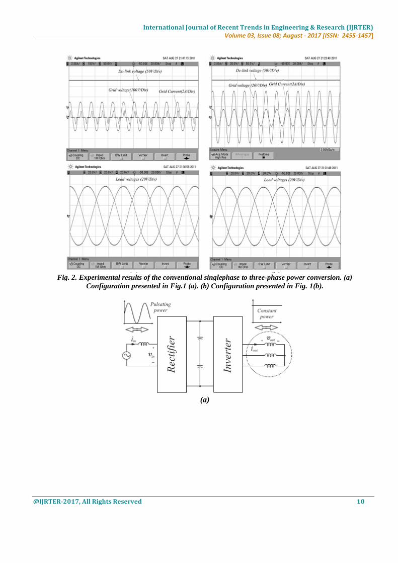
output converter sides can be controlled, as observed in Fig. 2(b). On the other hand, the configuration
presented in Fig. 1(a) represents a cheaper solution but without any control of the input current and dc-
link voltage, as observed in Fig. 2(a).

International Journal of Recent Trends in Engineering & Research (IJRTER) Volume 03, Issue 08; August - 2017 [ISSN: 2455-1457]
@IJRTER-2017, All Rights Reserved 9
(a)
(b)
Fig.1. Conventional single-phase to three-phase configurations: (a) Diode bridge at the input converter side (b)
Controlled rectifier at the input converter side.
In this paper, a single-phase to three-phase drive system composed of two parallel single-phase rectifiers
and a three-phase inverter is proposed. The proposed system is conceived to operate where the single-
phase utility source is the unique option available. Compared to the conventional topology, the proposed
system permits to reduce the rectifier switch currents, the total harmonic distortion (THD) of the grid
current with same switching frequency or the switching frequency with same THD of the grid current,
and to increase the fault tolerance characteristics. In addition, the losses of the proposed system may be
lower than that of the conventional counterpart. The aforementioned benefits justify the initial
investment of the proposed system, due to the increase of number of switches.
International Journal of Recent Trends in Engineering & Research (IJRTER) Volume 03, Issue 08; August - 2017 [ISSN: 2455-1457]
@IJRTER-2017, All Rights Reserved 10
Fig. 2. Experimental results of the conventional singlephase to three-phase power conversion. (a)
Configuration presented in Fig.1 (a). (b) Configuration presented in Fig. 1(b).
(a)

International Journal of Recent Trends in Engineering & Research (IJRTER) Volume 03, Issue 08; August - 2017 [ISSN: 2455-1457]
@IJRTER-2017, All Rights Reserved 11
(b)
(c)
Fig. 3. Single-phase to three-phase power conversion. (a) Type of power processed by rectifier and inverter
circuits. (b) Solution employed in [15]. (c) Solution employed in [16].
Fig 3. Shows the single-phase to three-phase power conversion with parallel configuration. Another
important characteristic observed in the single-phase to three-phase power converters that also has been
considered in this paper is the irregular distribution of power losses among the switches of the converter, as observed in Fig. 4. It means that, for a 600 V 50A class of insulated gate bipolar transistor (IGBT),
63% of the total losses measured in the single-phase to three-phase converter is concentrated in the
rectifier circuit, while the rest 37% is observed in the inverter circuit. With those numbers, it is possible
to measure the stress by switch, which means that each rectifier switch is responsible for 15.7% of the
total converter losses, while each inverter switch is responsible for only 6.1%. The loss per switch gives
an important parameter regarding the possibilities of failures in the power converters.

International Journal of Recent Trends in Engineering & Research (IJRTER) Volume 03, Issue 08; August - 2017 [ISSN: 2455-1457]
@IJRTER-2017, All Rights Reserved 12
single-phase source, one open-end three-phase motor, inductor filters (La, Lb, L’b, and L’a), converters
1, 2, 3, and 4, and two dc-link capacitor banks. If the legs are substituted by pulsed voltage sources, the
proposed converter can be modelled as in Fig. 5.
Fig. 5. Proposed single-phase to three-phase drive system. To avoid the circulating current, the following three
approaches are used commonly
i. Isolation. In this approach, the overall parallel system is bulky and costly because of additional power
supplies or the ac line-frequency transformer.
ii. High impedance. They cannot prevent a low frequency circulating current.

International Journal of Recent Trends in Engineering & Research (IJRTER) Volume 03, Issue 08; August - 2017 [ISSN: 2455-1457]
@IJRTER-2017, All Rights Reserved 13
iii. Synchronized control. This approach is not suitable for modular converter design. When more
converters are in parallel, the system becomes very complicated to design and control.
In this proposed method the system is designed to reduce the circulating current (Io). From fig.5.the
following equations can be derived for the front end rectifier.
In this ideal case, the circulating current can be reduced to zero imposing
When Ia = 0 then ia = i’ a and ib = i’b and the system model reduced to Fig. 4. Converter power losses
distribution in both rectifier and inverter units: 63% in the rectifier circuit and 37% in the inverter one.
Power losses in each switch of the rectifier (15.7%) and inverter (6.1%).
II. SYSTEM MODEL
This section will present the model of the proposed configuration. Such a configuration is constituted by
a
Where p = d/dt and symbols like r and l represent the resistances and inductances of the input inductors.
The circulating current io can be defined from ia and i’ a or ib and i’b i.e.
By solving the above equations,
In order to both facilitate the control and share equally current, voltage, power between the rectifiers, the
four inductors should be equal. i.e. r’s= ra = r’a = rb= r’b And l’s =la =l’a =lb =l’b. In this case the
equation can be simplified to the model given by

International Journal of Recent Trends in Engineering & Research (IJRTER) Volume 03, Issue 08; August - 2017 [ISSN: 2455-1457]
@IJRTER-2017, All Rights Reserved 14
III. CONTROL STRATEGY
The gating signals are obtained by comparing pole voltages with one (vt1), two (vt1 and vt2) or more
high frequency triangular carrier signals. In the case of double carrier approach, the phase shift of the
two triangular carrier signals (vt1 and vt2) is 1800. The parameter μ changes the place of the voltage
pulses related to va and vb. When vx* = vx*min (μ = 0) or v x* = vx*max (μ = 1) are selected, the
pulses are placed in the beginning or in the end of half period (Ts) of the control block diagram of Fig.
2, highlighting the control of the rectifier. To control the dc-link voltage and to guarantee the grid power
factor close to one. Additionally, the circulating current io in the rectifier of the proposed system needs to be controlled. In this way, the dc-link voltage vc is adjusted to its reference value v c* using the
controller Rc, which is a standard PI type controller. This controller provides the amplitude of the
reference grid current Is*. To control power factor and harmonics in the grid side, the instantaneous
reference current Is* must be synchronized with voltage e.g., as given in the voltage-oriented control
(VOC) for three-phase system. This is obtained via blocks Ge-ig, based on a PLL scheme Fig 6. The
reference currents I a*and ib* are obtained by making ia* = ib* = Is* /2, which means that each rectifier
receives half of the grid current. The control of the rectifier currents is implemented using the controllers
indicated by blocks Ra and Rb.
These current controllers define the input reference voltages va*and vb*. The homo polar current is
measured (io) and compared to its reference (io* = 0). The error is the input of PI controller Ro, that
determines the voltage vo*. The motor there-phase voltages are supplied from the inverter (VSI). Block
VSI-Ctr indicates the inverter and its control. The control system is composed of the PWM command
and a torque/flux control strategy (e.g., field-oriented control or volts/hertz control).

International Journal of Recent Trends in Engineering & Research (IJRTER) Volume 03, Issue 08; August - 2017 [ISSN: 2455-1457]
@IJRTER-2017, All Rights Reserved 15
Fig. 6. Control block diagram
IV. HARMONIC DISTORTION
As we know that harmonic distortion of the proposed converter and its voltages had been analysed with
the help of weighted THD (WTHD). It is solved by using
Where is treated as amplitude of fundamental voltage and is treated as amplitude of Ith harmonic and
also p may be number of harmonics in this consideration.
V. SIMULATION MODEL
To study the operation of the Three-Phase Drive System, it is implemented in MATLAB/SIMULINK
environment. The model is shown in Fig.7

International Journal of Recent Trends in Engineering & Research (IJRTER) Volume 03, Issue 08; August - 2017 [ISSN: 2455-1457]
@IJRTER-2017, All Rights Reserved 16
Fig. 7. Simulation model of single phase to three phase drive system using two parallel single phase rectifiers
VI. RESULT
The simulation results were obtained with the grid- and machine-phase voltages equal to 127 Vrms, dc-
link voltage of 225 V, capacitance of 2200 μF, and input inductor filters with resistance and inductance
given respectively by 0.1Ω and 2.6 mH. The load power was of 5 kVA. Fig. 8 shows selected simulation
results for the proposed system. Such results were collected using double-carrier-based PWM with μ = 0
for the input converters (converters 1 and 3), while a single carrier-based PWM with μ = 0.5 is
employed for the output converters (converters 2 and 4). Fig. 8 highlights the main control objectives
handled by the proposed single-phase to three-phase power converter. Fig. 8 (a) shows the ability of the
proposed converter to control the grid current with a sinusoidal waveform and power factor close to one.
While Fig. 8 (b) and (c) demonstrate that the input rectifier currents (i1a and i3a ) are in fact half of the
grid current due to the parallel connection at the grid side, Fig. 8 (d) shows the control of the circulating
current. Both dc-link voltages are under control, as observed in Fig. 8 (e) and (f). As expected, there is a
pulsating power at the dc-link capacitors due to the type of power from the single-phase grid. Since the
three phase power demanded by the three-phase machine is constant, the oscillating power from the grid
appears at the capacitors. Fig. 8 (g) and (h) show the currents and voltages of the machine. Notice that
the load voltages were filtered with a low-pass filter (LPF) to prove the converter’s capability to
generate 127 Vrms.

International Journal of Recent Trends in Engineering & Research (IJRTER) Volume 03, Issue 08; August - 2017 [ISSN: 2455-1457]
@IJRTER-2017, All Rights Reserved 17
(a)
(b)
(c)
(d)

International Journal of Recent Trends in Engineering & Research (IJRTER) Volume 03, Issue 08; August - 2017 [ISSN: 2455-1457]
@IJRTER-2017, All Rights Reserved 18
(e)
(f)
(g)
(h)
Fig. 8. Simulation results: (a) voltage and current of the grid, (b) input current of the converter 1, (c) input
current of the converter 2, (d) circulating current,(e) dc-link voltage in C12, (f) dc-link voltage in C34, (g) load
currents, and (h) load voltages.
VII. CONCLUSION
A single-phase to three-phase drive system composed of two parallel single-phase rectifiers, a three-
phase inverter and an induction motor was proposed. The system combines two parallel rectifiers
without the use of transformers. The system model and the control strategy, including the PWM

International Journal of Recent Trends in Engineering & Research (IJRTER) Volume 03, Issue 08; August - 2017 [ISSN: 2455-1457]
@IJRTER-2017, All Rights Reserved 19
technique, have been developed. The complete comparison between the proposed and standard
configurations has been carried out in this paper. Compared to the conventional topology, the proposed
system permits to reduce the rectifier switch currents, the THD of the grid current with same switching
frequency or the switching frequency with same THD of the grid current and to increase the fault
tolerance characteristics. In addition, the losses of the proposed system may be lower than that of the
conventional counterpart. The initial investment of the proposed system (due to high number of
semiconductor devices) cannot be considered a drawback, especially considering the scenario where the
cited advantages justify such initial investment. The experimental results have shown that the system is
controlled properly, even with transient and occurrence of fault.
REFERENCES I. A. H. Maggs, ―Single-phase to three-phase conversion by the ferrarisarno system,‖ Electr. Eng.—Part I, General,
J. Inst., vol. 93, no. 32, pp.133–136, Aug. 1946.
II. K. Hisano, H. Kobayashi, and T. Kobayashi, ―A new type single-phase to three-phase converter,‖ IEEE Trans.
Magn., vol. 2, no. 3, pp. 643–647, Sep. 1966.
III. S. Dewan and M. Showleh, ―A novel static single-to three-phase converter,‖ IEEE Trans. Magn., vol. 17, no. 6,
pp. 3287–3289, Nov. 1981.
IV. M. Liserre, ―Dr. Bimal K. Bose: A reference for generations [editor’s column],‖ IEEE Ind. Electron. Mag., vol.
3, no. 2, pp. 2–5, Jun. 2009.
V. F. Blaabjerg, A. Consoli, J. A. Ferreira, and J. D. van Wyk, ―The future of electronic power processing and
conversion,‖ IEEE Trans. Ind. Appl., vol. 41, no. 1, pp. 3–8, Jan./Feb. 2005.
VI. F. W. Gutzwiller, ―Thyristors and rectifier diodes-the semiconductor workhorses,‖ IEEE Spectrum, vol. 4, no. 8,
pp. 102–111, Aug. 1967.
VII. A. Elasser, M. H. Kheraluwala, M. Ghezzo, R. L. Steigerwald, N. A. Evers, J. Kretchmer, and T. P. Chow, ―A
comparative evaluation of new silicon carbide diodes and state-of-the-art silicon diodes for power electronic
applications,‖ IEEE Trans. Indust. Appl., vol. 39, no. 4, pp. 915– 921, Jul. /Aug. 2003.
VIII. M.-K. Nguyen, Y.-G. Jung, and Y.-C. Lim, ―Single-phase AC– AC converter based on quasi-z-source topology,‖
IEEE Trans. Power Electron., vol. 25, no. 8, pp. 2200–2210, Aug. 2010.
IX. M.-K. Nguyen, Y. cheol Lim, and Y.-J. Kim, ―A modified single-phase quasi-z-source AC–AC converter,‖ IEEE
Trans. Power Electron., vol. 27, no. 1, pp. 201–210, Jan. 2012.
X. B. Saint, ―Rural distribution system planning using smart grid technologies,‖ in Proc. Rural Electric Power
Conf., Apr. 2009, pp. B3-1–B3-8.
XI. A. R. C. de Lima Montenegro Duarte, U. H. Bezerra, M. E. de Lima Tostes, and G. N. da Rocha Filho,
―Alternative energy sources in the Amazon,‖ IEEE Power Energy Mag., vol. 5, no. 1, pp. 51–57, Jan./Feb. 2007.
XII. X. Wang, H. Zhong, Y. Yang, and X. Mu, ―Study of a novel energy efficient single-phase induction motor with
three seriesconnected windings and two capacitors,‖ IEEE Trans. Energy Convers., vol. 25, no. 2, pp. 433– 440,
Jun. 2010.
XIII. M. Khan, I. Husain, and Y. Sozer, ―Integrated electric motor drive and power electronics for bidirectional power
flow between the electric vehicle and DC or AC grid,‖ IEEE Trans. Power Electron., vol. 28, no. 12, pp. 5774–
5783, Dec. 2013.
XIV. Y.-S. Lai, W.-T. Lee, Y.-K. Lin, and J.-F. Tsai, ―Integrated inverter/converter circuit and control technique of
motor drives with dual mode control for EV/HEV applications,‖ IEEE Trans. Power Electron., vol. 29, no. 3, pp.
1358–1365, Mar. 2014.
XV. C. B. Jacobina, E. C. dos Santos, Jr, N. Rocha, and E. L. Lopes Fabricio,―Single-phase to three-phase drive
system using two parallel single-phase rectifiers,‖ IEEE Trans. Power Electron., vol. 25, no. 5, pp. 1285–1295,
May 2010.
XVI. C. Jacobina, E. Cipriano dos Santos, N. Rocha, de Sa, B. Gouveia, and E. da Silva, ―Reversible ac drive systems
based on parallel ac-ac dc-link converters,‖ IEEE Trans. Ind. Appl., vol. 46, no. 4, pp. 1456–1467, Jul./Aug. 2010.
XVII. Y. Ohnuma and J. I. Itoh, ―A control method for a single-tothree- phase power converter with an active buffer
and a charge circuit,‖ in Proc. Energy Convers. Congr. Expo., Sep. 2010, pp. 1801–1807.
XVIII. Y. Ohnuma and J. Itoh, ―Space vector modulation for a single phase to three phase converter using an active
buffer,‖ in Proc. Int. Power Electron. Conf., Jun. 2010, pp. 574–580.

International Journal of Recent Trends in Engineering & Research (IJRTER) Volume 03, Issue 08; August - 2017 [ISSN: 2455-1457]
@IJRTER-2017, All Rights Reserved 20
XIX. J. Holtz, ―Pulse width modulation for electronic power conversion,‖ Proc. IEEE, vol. 82, no. 8, pp. 1194–1214,
Aug. 1994.
XX. A. M. Trzynadlowski, R. L. Kirlin, and S. F. Legowski, ―Space vector PWM technique with minimum
switching losses and a variable pulse rate,‖ IEEE Trans. Ind. Electron., vol. 44, no. 2, pp. 173–181, Apr. 1997.
XXI. O. Ojo and P. M. Kshirsagar, ―Concise modulation strategies for four-leg voltage source inverters,‖ IEEE Trans.
Power Electron., vol. 19, no. 1, pp. 46–53, Jan. 2004.
XXII. C. B. Jacobina, A. M. N. Lima, E. R. C. da Silva, R. N. C. Alves, and P. F. Seixas, ―Digital scalar pulse-width
modulation: A simple approach to introduce non-sinusoidal modulating
waveforms,‖ IEEE Trans. Power Electron., vol. 16, no. 3, pp. 351–359, May 2001.
XXIII. M. Malinowski, M. P. Kazmierkowski, and A. M. Trzynadlowski, ―A comparative study of control techniques
for PWM rectifiers in AC adjustable speed drives,‖ IEEE Trans. Power Electron., vol. 18, no. 6, pp. 1390–1396,
Nov. 2003.
XXIV. P. Verdelho and G. D. Marques, ―Four-wire current-regulated PWM voltage converter,‖ IEEE Trans. Ind.
Electron., vol. 45, no. 5, pp. 761–770, Oct. 1998.
XXV. H. Abu-Rub, J. Guzinski, Z. Krzeminski, and H. Toliyat, ―Predictive current control of voltage-source inverters,‖
IEEE Trans. Ind. Electron., vol. 51, no. 3, pp. 585–593, Jun. 2004.
XXVI. G. Dong and O. Ojo, ―Current regulation in four-leg voltagesource converters,‖ IEEE Trans. Ind. Electron., vol.
54, no. 4, pp. 2095–2105, Aug. 2007.
XXVII. C. B. Jacobina, M. B. de R. Correa, R. F. Pinheiro, E. R. C. da Silva, and A. M. N. Lima, ―Modeling and control
of unbalanced three-phase systems containing PWM converters,‖ IEEE Trans. Ind. Appl., vol. 37, no. 6, pp. 1807–
1816, Nov./Dec. 2001.
XXVIII. Euzeli Cipriano dos Santos, Nady Rocha, Member, and Cursino Brandao Jacobina˜, ―Suitable Single-Phase to
Three-Phase AC– DC–AC Power Conversion System,‖ IEEE Trans. Power Electronics, vol.30, No.2, February
2015
RASHMIKA.DHOOMALA was born in Warangal; in 1993.She has done his Bachelor of Engineering
in Electrical & Electronics Engineering in 2014 from Vaagdevi Engineering College (affiliated to JNTUH), Warangal. She
Pursuing M.Tech (POWER ELECTRONICS) in the year 2014-2016 from Vaagdevi College of Engineering, Autonomous,
Warangal. Areas of interest are Power Electronics, Smart grids, Control systems and Power systems.
NOORULLAH.MOHAMMAD was born in Warangal, in 1985.He has done his Bachelor of
Engineering in Electrical & Electronics Engineering in 2007 from Ramappa Engineering college (REC) (affiliated to
JNTUH), Warangal. He completed M.Tech (POWER ELECTRONICS) in the year 2014 from Vaagdevi College of
Engineering (affiliated to JNTUH), Warangal. He has 2 year of work experience as an Assistant prof. in Electrical
Engineering and since 2014 working as an Asst. prof in Vaagdevi Engineering College, Warangal. Areas of interest are
Power Electronics and Control systems and Power systems.