
MODELING OF GAS TURBINE ENGINES, HEAT RECOVERY...
32
MODELING OF GAS TURBINE ENGINES, HEAT RECOVERY STEAM GENERATORS, AND COMBINED CYCLES USING PEPSE Gene L. Minner SCIENTECH, Inc. 440 West Broadway Idaho Falls, ID 83402
Transcript of MODELING OF GAS TURBINE ENGINES, HEAT RECOVERY...
MODELING OF GAS TURBINE ENGINES, HEAT
RECOVERY STEAM GENERATORS, AND
COMBINED CYCLES USING PEPSE
Gene L. Minner
SCIENTECH, Inc.
440 West Broadway
Idaho Falls, ID 83402

MODELING OF GAS TURBINE ENGINES, HEAT
RECOVERY STEAM GENERATORS, AND
COMBINED CYCLES USING PEPSE
By
Gene L. Minner
SCIENTECH, Inc.
440 West Broadway
Idaho Falls, ID 83402
ABSTRACT
Guidance is provided for PEPSE modeling of gas turbine engines, heat recovery steam
generators, and combined cycle plants. Suggestions for modeling are based on experience gained
in developing computational coding and in making models of numerous arrangements of
combined cycle units. Some of the details are specific to the latest version of PEPSE that is in
development, Version 64 and GT3.0.
5-1
INTRODUCTION
Considerable attention and emphasis is being given to electric power generation systems
that include gas turbine (GT) engines, heat recovery steam generators (HRSG’s),
supplemental firing, and combined cycles (CC’s) that include both gas and steam turbines.
These systems frequently provide significant improvements in operating efficiencies and
reductions of pollutant emissions compared to older “conventional” power generation
systems.
The need for computational tools to perform heat balance engineering calculations for
these systems has arisen with this new emphasis. Recent enhancements in PEPSE have
responded to these needs.
While the ability to analyze HRSG’s has existed for over five years in PEPSE, experience
has shown difficulties in applications in some cases. These difficulties have been the result
of the complexity of the systems and the standard methods (in the industry) of
representing the performance of HRSG stages. Understanding these computational
hurdles can be a benefit by providing direction and reducing frustration in doing the
analyses. In addition, understanding contributes to improvements in the program, devoted
to modifying the computations to improve robustness. A compilation of a list of modeling
techniques that work has been assembled. This report primarily discusses a group of
modeling techniques that we have found useful in HRSG applications. However,
occasional reference is also made to coding improvements that have provided significant
benefits.
Included in the discussions here are several example models that illustrate the techniques
discussed. When these examples are presented in schematic form, the computed results
for analysis cases are included on the figures. The necessary details of modeling are
described in Reference 1.
5-2
Any current PEPSE-GT Version 3.0 customer can access several of the models used here.
The combined cycle models that are discussed in this paper are delivered with the
installation disk of the PEPSE-GT program. These models are called COMBCY1,
COMBCY2, COMBCY3, and COMBCY4, respectively, in the order in which they appear
in this paper.
SYSTEMS FOR CONSIDERATION
The systems involved in GT and CC applications can vary from the simple to the complex.
The current versions of PEPSE and PEPSE-GT can be used to model this full range of
complexity. Reference 2 gives a wide variety of examples of system arrangements and
strategies for CC applications.
The simplest kind of system would be a GT engine driving a generator, with the hot
exhaust gases passing out to atmosphere without further processing. A PEPSE model of
such a system is shown in Figure 1. The purpose of such a model may be to calculate the
electricity generated at design or off-design conditions or to calculate the air pollutant
emissions for the GT.
The power generation system becomes more complex if we choose to improve the
efficiency by passing the GT’s exhaust gases through heat exchangers to extract energy
from the gas and reduce the temperature before the gas is discharged to atmosphere. The
energy recovered by the heat exchangers can be used for a variety of applications. A few
of these include heating of steam for injection into the combustion zone of the GT itself,
or heating steam for sendout to some off-site process, or heating of steam for driving a
steam turbine cycle. An example system that includes a HRSG for steam turbine
applications is shown in Figure 2, which is model COMBCY1. The system has two GT
engines having their exhaust gases ducted to a HRSG. In this system the steam turbine is
provided “reheat” steam by the HRSG’s reheater stages, coupled with steam supplied by
the IP (intermediate pressure) HRSG loop. The LP (low pressure) portion of the HRSG

5-3
Figure 1
Schematic Diagram Of A Submodel With A Type 77 Component
To Represent A Gas Turbine Engine

5-4
Figure 2
Schematic Diagram Of A Combined Cycle Model That Includes A GT Engine Component,A HRSG, And A Steam Turbine, With Process Steam Sendout (COMBCYC1 Model)
5-5
provides steam to the LP steam turbine. In addition the coolest gas in the HRSG provides
water/steam heating in a drum loop for deaerating the steam.
Computational models of these kinds of systems and others have used the modeling
techniques that are discussed in this report.
The models that appear in this paper as illustrations, include several “SET’s” of
descriptions. These sets show varying ways of describing components and varying
methods of applying controls to meet modeling objectives. These sets are arranged in the
model “RUN” menus for multiple analysis “stacked” cases. Some of the cases use the
performance mode parameters, pinches and approaches; and some use the simplified
design mode heat transfer coefficients. Most of the techniques discussed in the balance of
this report are applied in these models.
GAS TURBINE MODELING
PEPSE Version 64, and older versions as well, provides tools for modeling GT engines in
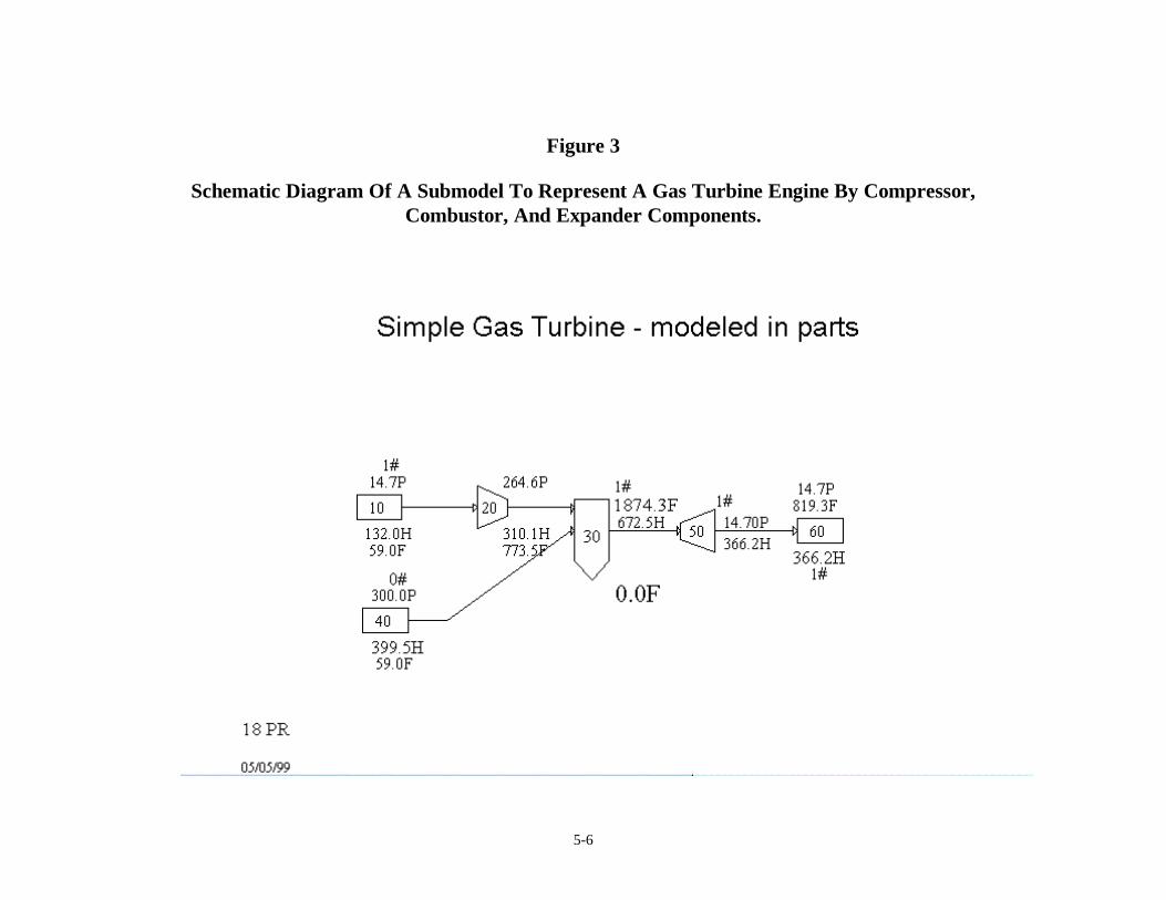
detail. Figure 3 shows a model that could be used on these PEPSE versions to analyze a
GT. As seen in the schematic, the model consists of a source of air flow, a source of fuel
flow, a Type 44 compressor component, a Type 70 combustor component, a Type 9 “gas
turbine” (expander) component, and a sink to receive the exhaust gas flow. Also included
in the input data for the model description would be a generator.
This model provides the opportunity to do detailed analysis of the effects of compressor
pressure ratio, of bleed flows from the compressor to turbine, of intercooling or
regeneration, and other assorted internal effects of the engine. User inputs for this model
would include pressure and heat losses, if any, compressor pressure ratio and efficiency
and turbine efficiency, and so forth. PEPSE Version 64 does not include built-in
correlations for the component parts’ efficiencies or pressure ratios of any specific
engines. Such information is proprietary to the engine manufacturers, generally closely
5-6
Figure 3
Schematic Diagram Of A Submodel To Represent A Gas Turbine Engine By Compressor,Combustor, And Expander Components.
5-7
guarded for their competitive benefit. However, PEPSE includes the tools that enable a
user to input these characterizations, in the form of performance “maps”, using schedules,
operations, curve fits, and compiled algorithms when the user is able to obtain such
proprietary information from a vendor.
Models such as this one can be used as shown, for analyzing the GT as a stand-alone, or
the significant parts could be included in a model of a larger system for more extensive
analyses.
The PEPSE-GT program provides the methods discussed above and additional GT
modeling capabilities. The schematic diagram shown in Figure 1 illustrates a submodel of
a GT engine, where a Type 77 component represents the complete engine. In addition to
this model, which focuses attention on the engine as a single entity, it is also possible to
use the Type 77 component in a larger system model, as shown in Figure 2.
The Type 77 component includes the compressor, combustor, and expander items within a
single PEPSE module. This GT engine component can be used to compute net electrical
generator power, the heat rate, the associated fuel and air inflow, the water or steam
injection flow, as applicable, and the exhaust gas flow and temperature. Performance
descriptions of over 400 available vendor GT engines are built into PEPSE. For the most
part, these descriptions have been extracted from the literature, such as reference 3. Data
also have been provided directly to us by vendors.
It is a simple matter for a modeler to select a specific vendor’s engine from a pick-list in
the PEPSE graphics program; whereupon the design-point key parameters are
automatically employed. These are: generator power, heat rate, engine flow rate, and
exhaust temperature. Calculations automatically account for operation at off-design
conditions. In addition to the built-in GT engine descriptions, it is possible for a modeler
to specify the key parameter values and the effects due to off-design operation for any
engine.
5-8
In addition to these tools, additional tuning factors are provided for use in closely
matching a specific calculation’s results with a tested or claimed performance item. In
addition, these tuning parameters can be used in order to obtain an energy balance for the
GT engine component in the results. We have found that energy balance tuning may be
needed because of difficulties in obtaining an exact energy balance based on the data
provided by the vendors. This may be a consequence of assumptions that we had to make
in obtaining closure of our calculations. Among these assumptions are: location of the
point where the engine flow rate is reported (the air inlet or the engine exhaust, the
heating value for the fuel, losses in the generator and its drive system, and others. There
are uncertainties and ambiguities about these and other points in the Reference 3
information.
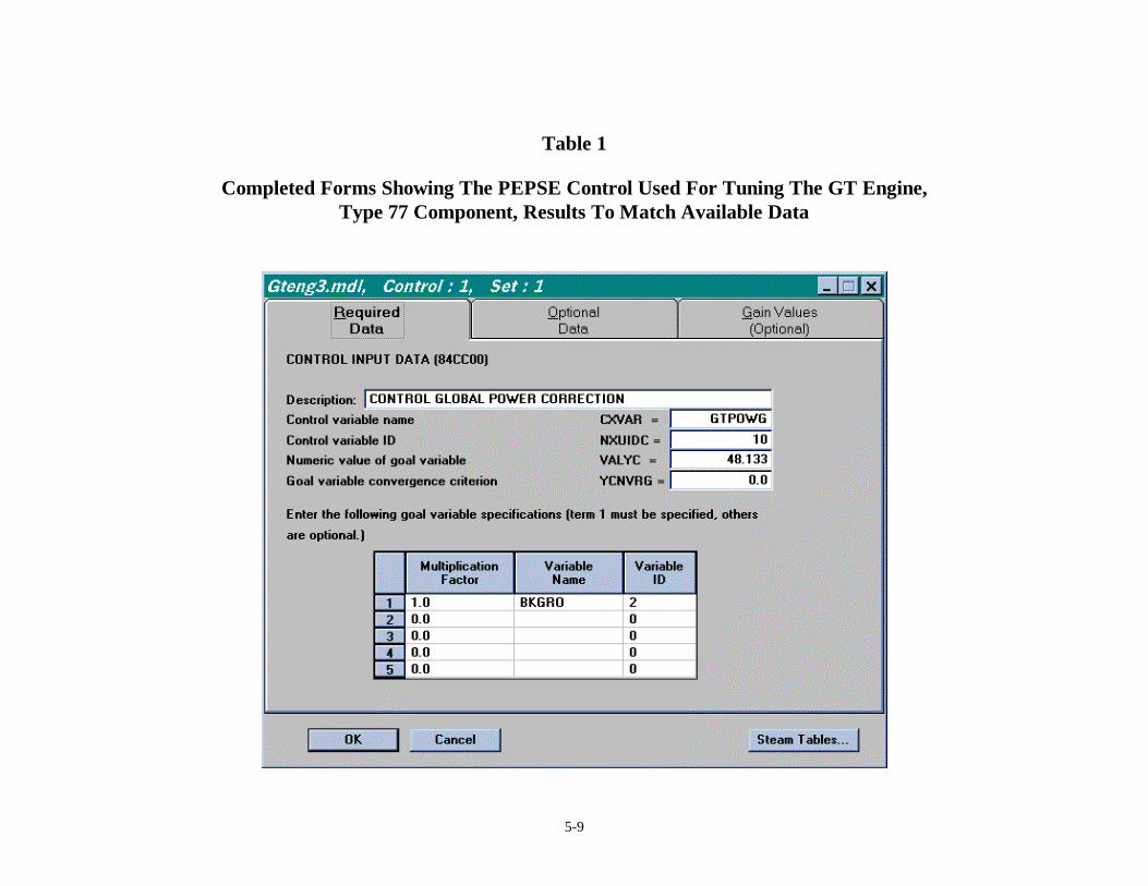
An example of a completed form for a control used to tune a gas turbine engine’s
generation factor is shown in Table 1. The control variable is GTPOWG, for turbine
component 10, with a goal value of 48.133 mW. The goal variable is BKGRO, for
generator number 2 in the model. The model includes similar controls for tuning the other
global factors to obtain heat rate, temperature, and flow. In this model all of the controls
were placed in a control block in order to account for the interdependencies of the
controls. Convergence was straightforward.
SIMPLE HRSG MODELING APPLICATION
A diagram of a simple HRSG modeling application is shown in Figure 4. In this system,
hot exhaust gases from the GT engine (not shown, but represented by a gas source
component) are passed through several stages of water and steam heat exchangers in a
heat recovery boiler. The heating provides evaporation for a deaerating loop and for a
single-pressure steam sendout to a process customer.
5-9
Table 1
Completed Forms Showing The PEPSE Control Used For Tuning The GT Engine,Type 77 Component, Results To Match Available Data
5-10
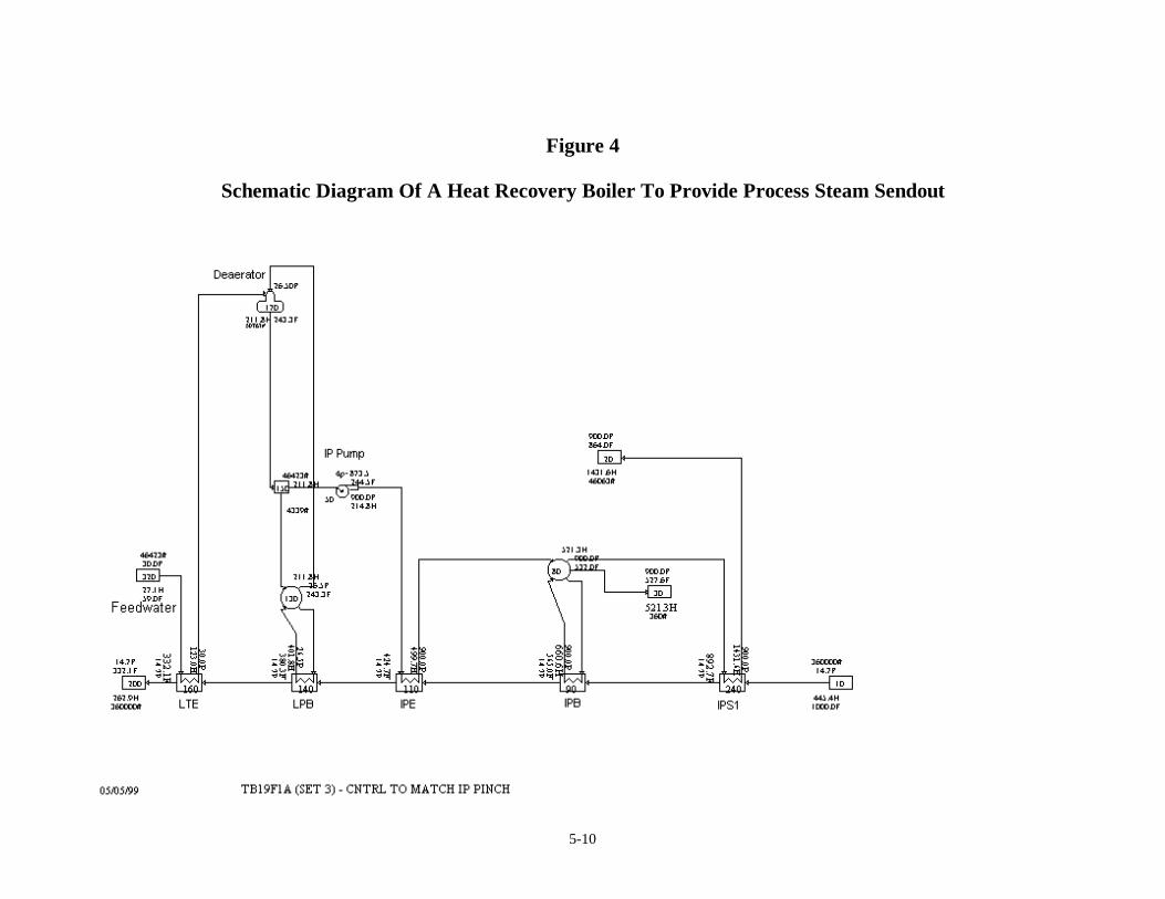
Figure 4
Schematic Diagram Of A Heat Recovery Boiler To Provide Process Steam Sendout
5-11
The significant components used in this model are the Type 28 heat exchangers to
represent the HRSG economizer, evaporator, and superheater stages, the Type 74 drum to
separate the steam and liquid, the Type 15 deaerator component, and the pump. It is
typical that the performance of the HRSG heat exchangers is represented by “performance
mode”, using a pinch value for the evaporator component and approach values for the
economizer and superheater components. Over some limited range of operation it is
common to assume that these performance parameters remain fixed. Note that the pinch
for the evaporator is a relation between the steam saturation temperature and the gas exit
temperature. The approach for the economizer is a relation between the steam saturation
temperature and the liquid-exiting temperature. For the superheater, the approach is the
difference between the gas entering temperature and the steam exiting temperature.
Use of the pinch for an evaporator in doing calculations can be especially troublesome.
This is because the pinch applies strictly at the operating point at which it was derived. If
excursions of steam-side pressure, or of gas incoming temperature, or of flow proportions
occur due to significant changes of operating point or due to iteration effects, the fact that
pinch dictates the gas outlet temperature can drive steam-side energy to unreasonable
values. This can abort the computation directly in the evaporator, or it can cause non-
physical results in a receiving component. Behavior of an evaporator in a computation
should be examined/monitored, especially in cases where there are difficulties in obtaining
a converged solution. Use of our suggested modeling techniques can be helpful in
resolving these troubles.
Also available in PEPSE are other, “design mode”, methods of characterizing the thermal
performance of the heat exchangers. The first of these is a simplified design-mode
calculation, where the heat transfer is characterized by an overall heat transfer coefficient,
which has a built-in adjustment according to flow rate. This mode can be useful for more
accurately predicting heat transfer over a wider range of operation than would be
reasonable for the pinch and approach method. The second method offers the opportunity
to perform a full design mode calculation, using the Type 28 component description much

5-12
as it is frequently used in modeling fossil boiler “convective stages”. In this method, the
user gives details such as tube diameters, lengths, thermal conductivities, and so forth.
From this information, the built-in hydraulic and thermal correlations, and the local
incoming conditions, PEPSE calculates the heat and hydraulic performance. This latter
method is more versatile and adaptive than the other two methods, but accumulating the
needed data is time consuming and is less commonly used in modeling combined cycle
systems.
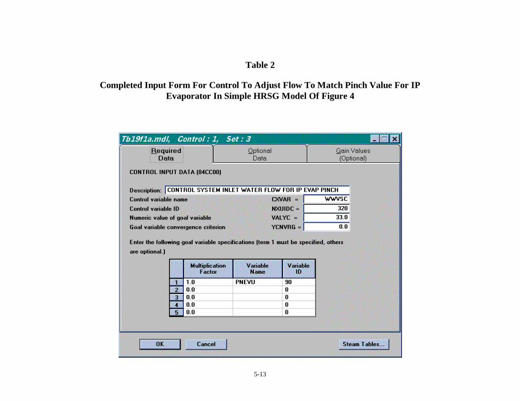
A control was written for this model to match a pinch value by adjusting the water-side
flow. The completed input form for this control is shown in Table 2. The control variable
is WWVSC, the flow at source component 320. The goal pinch value is 33.0 degrees, and
the goal variable is PNEVU, for component 90, the IP evaporator.
COMBINED CYCLE SYSTEMS INVOLVING GT, HRSG, STEAM TURBINE,
AND PROCESS SENDOUT STEAM
Combined cycle example systems are shown in schematic form in Figures 2, 5, 6, and 7.
The COMBCY1 cycle of Figure 2 has already been discussed in a previous section.
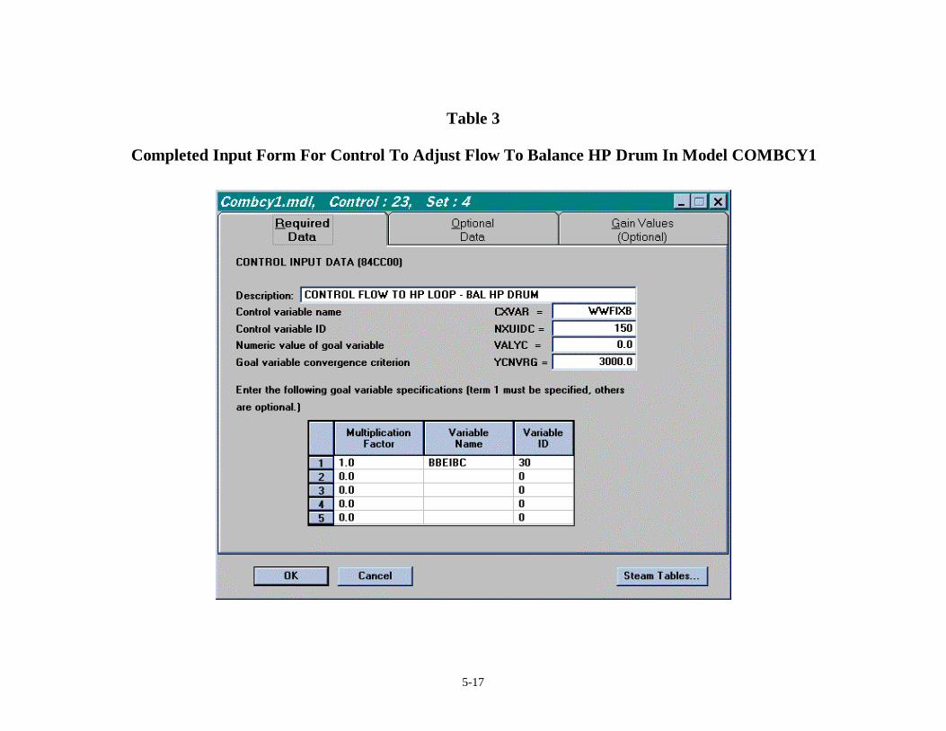
Mentioned here is the fact that this model includes an explicitly specified control to
calculate the flow needed to balance the HP drum, component 30. The completed input
form for this control is shown in Table 3. The control variable is WWFIXB for splitter
component 150. The goal value is zero, and the convergence criterion is a band of width
3000 Btu/hr. The goal variable is BBEIBC for component 30, the energy imbalance
variable.
The system of Figure 5, COMBCY2, shows results in SI engineering units. The principal
feature demonstrated by this system is that the steam turbine is a “back-pressure”
application. That is, there is no condenser present. Sendout steam is provided by the IP
HRSG drum loop and by the exhaust of the steam turbine. In addition the model provides
an option for supplemental duct firing to increase the heat available for use by the HRSG.
5-13
Table 2
Completed Input Form For Control To Adjust Flow To Match Pinch Value For IPEvaporator In Simple HRSG Model Of Figure 4

5-14
Figure 5
Schematic Diagram And Results In SI Engineering Units For A Combined CycleWith A Backpressure Steam Turbine And Supplemental Duct Firing. (COMBCYC2 Model)
5-15
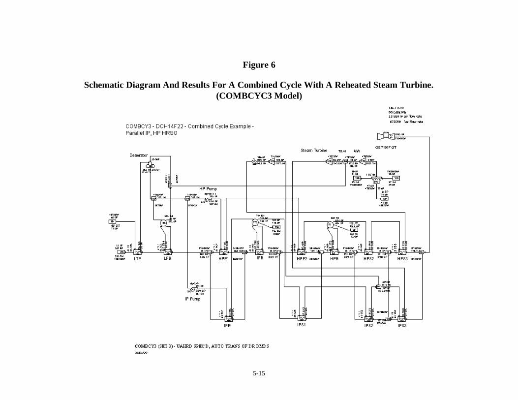
Figure 6
Schematic Diagram And Results For A Combined Cycle With A Reheated Steam Turbine.(COMBCYC3 Model)
5-16
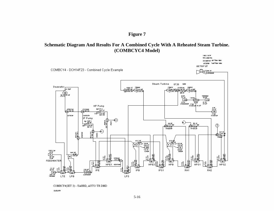
Figure 7
Schematic Diagram And Results For A Combined Cycle With A Reheated Steam Turbine.(COMBCYC4 Model)
5-17
Table 3
Completed Input Form For Control To Adjust Flow To Balance HP Drum In Model COMBCY1

5-18
The cycle model, COMBCY3, in Figure 6 shows HRSG arrangements where there are
heat exchanger stages modeled in parallel on the gas path. For example, HP economizer
2, component 100, is in parallel with IP superheater 1, component 364. In such instances,
it may be a little tricky to determine the correct amount of gas-side split to send to the two
branches. PEPSE controls can be used for this purpose when the vendor heat balance has
provided waterside performance information. Recognize that, in the real system, the gas
flow does not actually split; rather, the two heat exchangers are immersed in the gas
stream at the same longitudinal position of the gas flow.
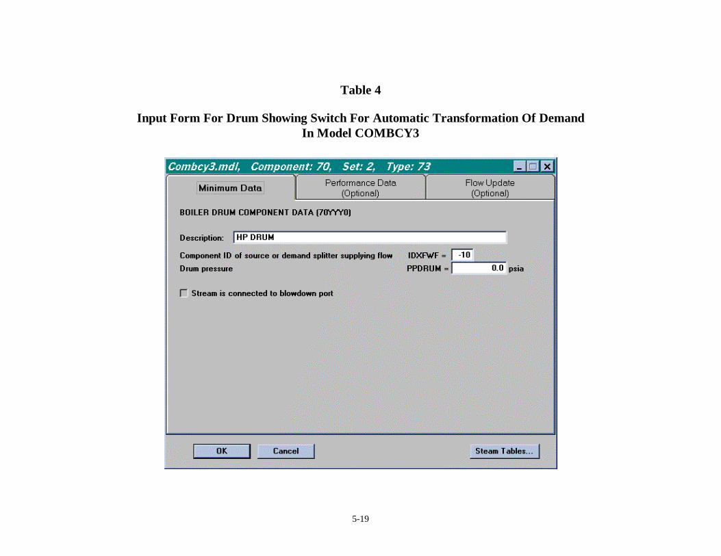
This model illustrates one of the suggestions listed in the following section, the use of the
automatic transformation of drum demand into a control and subsequently into a control
block. This occurs in Set 2 of the data. Table 4 shows the completed data form for the
HP drum component 70 for this purpose. The minus sign on input IDXFWF provides the
signal to PEPSE for the transformation.
The cycle shown in Figure 7, model COMBCY4, shows additional variations of
arrangement that include HP steam for the steam turbine, IP and reheat steam, an LP loop
to the LP steam turbine, and a deaerating loop at the cool end of the HRSG’s gas path.
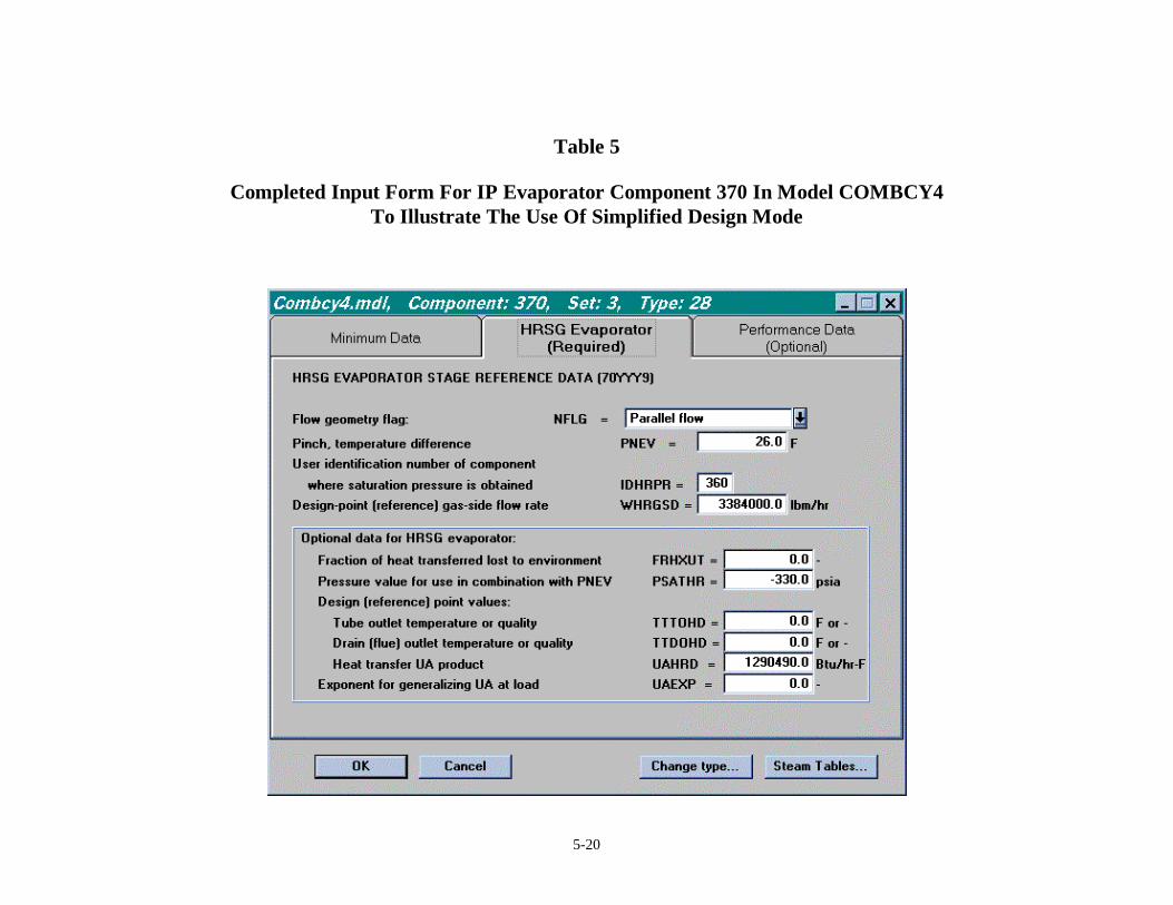
Table 5 is an example of a completed form for a heat exchanger, evaporator component
370 in Set 3 to show the specification of the heat transfer coefficient, input UAHRD. This
variable overrides the pinch that appears earlier on the form.
SPECIFIC TECHNIQUES ADVISED FOR MODELING COMBINED CYCLES
.
The following lessons have been learned in our experience modeling HRSG’s using
PEPSE and PEPSE-GT. More details are given to explain these items in the Appendix.
5-19
Table 4
Input Form For Drum Showing Switch For Automatic Transformation Of DemandIn Model COMBCY3
5-20
Table 5
Completed Input Form For IP Evaporator Component 370 In Model COMBCY4To Illustrate The Use Of Simplified Design Mode
5-21
1. Develop models starting from a heat balance or conceptual design.
2. For GT, make a submodel at design load. Tune the model. Incorporate in a system
model if desired.
3. Get your first experiences by modeling simple systems, e.g. HRSG submodel.
4. The success of initial run is enhanced by fixing flows and temperatures in your input.
5. Use a large ITRMAX.
6. Convergence is difficult. Loosen the mass and energy convergence criteria.
7. Caution - Be aware that some combinations of flows and heat transfer in systems are
not physically possible. Abnormal terminations or failed cases can result if you try to
specify such cases.
8. Including a drum component in the LP/D-A loop may help stability of numerics.
9. Always enter values for HRSG HX pinch or approach.
10. Include heat loss to environment in the input.
11. Obtaining drum energy balance is difficult. A control block is the best tool.
12. There is an automatic way available to set up a control block for drums.
13. You can write your own controls. This is more versatile than the automatic approach.
14. Subtle effects can occur in evaporator/drum loops, even in design mode.
15. Beyond min data info is frequently needed for evaporators and economizers.
16. Initiating runs with small flow values can cause steam and gas tables failures.
17. Deaerator loops are common at the LP end. Application of demand updating of the
D-A is generally successful.
18. Variations during iterations can erroneously indicate steam inlet to pumps. This can
produce calculation of unrealistic, large energy inputs to the water.
19. Systems that have low values of flow in any loop may be difficult to converge.
20. Parallel HX’s in the gas duct of a HRSG can present special modeling challenges.
21. Built-in backpressure calculations work well for HP and IP drums.
22. Alternative backpressure calculations may be required for LP drums.
23. Use Special Option 10 and a Type 34 valve at “automatic extractions”.
5-22
24. Some combinations of optional inputs (TTTOHD and TTDOHD) are inherently
numerically unstable.
See the Appendix for discussion of the details of these points.
SUMMARY
This report has discussed thermal, heat balance, modeling of gas turbine engines, heat
recovery steam generators, and combined cycles in electric power generation applications.
Many key recommendations have been made as guidance for use in developing these types
of models. These techniques have been shown to be successful in providing robust and
stable computational models. These efforts have been aided considerably by recent
numerical improvements in the PEPSE program itself.
REFERENCES
1. PEPSE and PEPSE-GT Volume 1 – User Input Description, G.L. Minner, et al, 1998.
2. R.W. Haywood, Analysis of Engineering Cycles, Fourth Edition, Pergamon Press,
Oxford, 1991.
3. Gas Turbine World 1998-99 Performance Specs, Volume 18, For Project Planning,
Engineering, Design and Procurement, Pequot Publishing, Inc., Southport, CT,
December 1998.
5-23
APPENDIX
This Appendix provides detailed discussions about the individual modeling
recommendations that were summarized in the main body of the paper.
1. In many cases, the modeling effort will begin by mimicking a heat balance that has
been provided by a vendor. This is similar to other PEPSE applications, such as steam
turbine cycle modeling, fossil boiler modeling, and nuclear steam generator modeling.
2. This discussion assumes that you are using a Type 77 component to model the GT
engine. PEPSE-GT includes built-in descriptions of GT engines as a single modeling
icon. These descriptions are available for over 400 machines. Design point and off-
design data are included. Make a submodel of the GT engine and choose the specific
model of interest from the pick-list in the graphics interface program. Run the
submodel and compare the results against information available to you. Pay particular
attention to the primary results variables -- generator power, heat rate, engine flow
rate, and engine exhaust temperature. Also look at the printed value of energy
imbalance. If there are significant differences, reconcile the differences. This may
involve toggling the input switch that selects front or rear of the engine as the point
where flow is calculated. It also may involve checking the sensitivity to the heating
value of the fuel. You may need to use PEPSE controls on the global tuning factors
for the GT engine component to match known values of the primary results variables.
Once you have tuned for the design load, run cases at off-design conditions and
compare the results to any information available to you. Perform tuning if necessary.
Tuning factors can be scheduled. If you have “correction factors” provided by the
vendor for the specific GT engine being analyzed, you can input these correction
factors for use by PEPSE-GT.
3. It is sometimes a good idea to get experience in this work by starting with simple
models. We have found it helpful to first build a submodel of the gas-turbine
component, as specified by the GT vendor, and to exercise the model to tune it to
emulate the vendor’s performance claims for the engine or as-tested performance. In

5-24
similar fashion, one can develop a stand-alone HRSG model and exercise it to learn its
characteristics. Sometimes one can learn important facts about these items, and one
can apply controls that are easy to understand in the submodel context. Such controls
might be harder to diagnose in a more complex full system model as a starting
modeling effort. Once the simpler system has been mastered, it is a natural step to
move on to the more complete system model.
4. Once you are modeling the full combined cycle, develop a base case that is simple.
This is a very useful way to gain confidence in the physical realism of the model. Here
“simple” means to include all of the necessary layout of the schematic, but to simplify
the input data. Specifically, helpful simplifications can include fixing the flows
throughout the system and fixing the pressures at the drums in the HRSG model,
rather than jumping immediately to the general case where these “float”. In order to
obtain a converged solution for this model, the energy results for the HRSG
evaporators will need to be auto-balanced. This balancing is done by specifying the
tube outlet quality in the input. The value of quality to use is (at the pressure of the
drum) the reciprocal of the circulation ratio in the drum loop (note that the ratio
defaults to 5.0). To accomplish this, in the performance mode, specify the tube outlet
temperature and use the “alternate meaning” as quality (input variable TTTOHD). This
is optional input data In this case, in order to have the flows fixed, the drum demand
references are entered as zeros A typical value of quality is 0.2.
5. Use a large ITRMAX (the maximum allowance of iteration counter). Several of our
models have required between 100 and 200 iterations to converge. Some may require
more 200.
6. Loosen the system convergence criteria (generic input EXTERR, CIRERR, and
ENEROR) to approximately 10 lbm/hr (.0013kg/s), 10 lbm/hr, and10,000 Btu/hr
(3000 W).
7. Combined cycle design is complex, and analysis is also complex. Sometimes, a
combination of conditions that you are trying to analyze may not be physically
possible. This can happen especially in relative miss-matches of water-side and gas-
side flows and water-side pressures, combined with selected values of pinches and
5-25
approaches for the heat exchangers in heat recovery steam generators. Therefore, if
you have an analysis case that will not converge, the cause may be a combination of
unattainable conditions. PEPSE does not tell you this directly, except by failing to
converge or by producing a steam table failure. On the other hand, some cases may
not converge because of selection of initial conditions that are too far away from the
final answer; this is an intrinsic hazard of numerical analyses where the calculations
begin with a guessed set of starting conditions. The example models that accompany
the PEPSE GT installation show several variations of techniques that we have found
successful in modeling combined cycles.
8. In our experience the calculations work best when the deaerator (D-A) drum loop in
the model includes a drum component. This improves the stability of the calculations.
You CAN exclude the drum, and you can make it work, but we have found this to be
more difficult.
9. HRSG HX’s should be declared as “economizer”, “evaporator”, or “superheater”, and
a non-zero value of pinch or approach should be entered, even if the intent is that one
of the later-appearing inputs, such as TTTOHD overrides the pinch or approach.
10. It is common to specify some heat loss to the environment for each HX. This
represents the heat loss from the HRSG duct. Specification is done as a fraction of the
gas-side heat transfer in the HX. Typical values of this fraction (input variable
FRHXUT) are in the range .01 to .02.
11. When drum (Type 73) components are involved in HRSG’s, the drum demand
reference, input variable IDXFWF, will generally be successful to analyze fairly simple
cases. The demand supplier for this purpose will typically be a source component or
demand splitter at the originating location for the water-side flow for the affected
drum. Intervals, input variable IUPD07, in the range of 5 to 10 are typically required.
This is the easiest case to set up to run an analysis If a system is complex, most cases
will not be solved by this approach, and abnormal terminations will result. Greater
sophistication is needed for these systems.

5-26
12. Many system analyses will not converge, i.e. they will give ABNORMAL
TERMINATION at the end of the run, with the use of the drum demand reference,
input IDXFWF. When this occurs, alternative, more robust, computational tools are
required in order to attain a converged solution. Generally, non-convergence of the
drum demand calculations is caused by the interdependencies of effects among drum
loops and multiple HX’s, whereas the demand calculations are not effective in
accounting for these interdependencies. PEPSE’s Control Block feature is effective.
The next easiest way to do this is to flag automatic setup of controls and a control
block via your input of word IDXFWF for the drum. This is a feature added to the
program during the development of Version 64 and GT3.0. The flag is set by placing
a minus sign in front of the ID entered in the IDXFWF space As long as you have
cited a valid demand component ID, PEPSE will do all the rest of the work of creating
the needed controls and the control block. If you have other controls in your model,
the run will be best-behaved if ALL of the controls in the model are included in the
control block. You can place your specified controls in a control block via the
standard mechanism for creating a control block. Any controls created automatically
by PEPSE will be automatically added to the control block that you have created.
13. At the next level of complexity in usage is writing your own controls and your own
control block, instead of using the drum demand as described above. In doing this,
you have more options relative to the way that you specify the controls and the block.
First of all, the drum demand, IDXFWF; is to be zero. The automated process would
have written a control on flow rate to minimize the energy imbalance, BBEIBC, for
the drum component. If you set up your own control to balance a drum, you could
choose to make the pinch of the evaporator the control variable, or some other choice.
NOTE THAT, whether you set up your control as described here or use the
automated option in the item immediately above, the evaporator in the drum loop must
NOT be auto-balanced. That is, do NOT specify a value of quality (TTTOHD) at the
tube outlet of the evaporator. Instead, use pinch, or TTDOHD, in performance mode,
or use UAHRD in design mode for the evaporator specification. You do, of course,
also have the option to represent the HX in full design mode, Type 28 component. In
5-27
the event that you choose to write your own control block, some cases may be helped
by specifying optional data word IBGCBL with a value of 20 or 25 (the automated
control block sets this by default). This will start the control block calculations later
than might occur by default. We have found in some cases that starting the control
block early (by default) can cause troubles in the numerical solution of the control
block.
14. Just for your information, be aware that, in any application of a drum-evaporator loop,
where the UAHRD has been specified for the evaporator and where the water-side
pressure is fixed and the incoming gas flow and temperature are fixed, the amount of
steam production will be fixed and the pinch will be fixed. Even if you vary the water-
side flow, the amount of steam produced will not change, and the pinch will not
change. This is a consequence of the heat transfer calculation, which is Q = UA *
LMTD.
15. For economizers and evaporators, it is advisable to enter a reasonable value for input
variable PSAHTR, preceded by a minus sign. This causes the value to be used initially
and for any fixups that may be required during later iterations.
16. If you specify a pinch (or a gas-side outlet temperature) value for an evaporator, you
need also to specify a reasonable value of water-side flow through the evaporator.
Failing to do so is susceptible to trouble because the gas-side temperature specification
determines the amount of energy that will be passed from the gas side to the water
side. A small amount of water flow would produce an inordinate rise in enthalpy and
temperature and result in probable steam table troubles. While PEPSE has been coded
to catch and fix up many such troubles, there is still potential for unexpected results to
occur. Among other things, repeated use of fixups can lead to bogus values of “gains”
calculated for control blocks, leading to difficulties of convergence of this feature.
17. If there is a deaerator component (D-A) associated with the HRSG, it is appropriate to
use a PEPSE Type 15 component to represent this item. The demand ID, IDXTGE,
for the D-A can be used to point to a demand splitter, where the flow will be adjusted
in order to attain an energy balance for the D-A. Typically, the D-A is included in a
low pressure drum loop at the back end (gas-side) of the HRSG. Because this is a
5-28
closed loop, PEPSE would have trouble choosing an order of solution without your
help. You can help PEPSE by making one of the streams in the loop a Type 6, for
impasse resolution. At this stream you will need to enter initial-guess values of
pressure, temperature (or quality), and flow rate. In some instances, the guessed value
of pressure will be the value that is retained throughout the solution in the LP loop.
There are two specific streams that seem to work well for this, either the steam inlet to
the D-A or the drain outlet from the D-A. In both cases, it is an easy matter to specify
the quality (1.0, and 0.0, respectively). We have had success with two different
scenarios in the LP drum loop. In the first you can actually use a Type 73 drum
component and a Type 28 evaporator component (with the tube exit quality set to the
inverse of the circulation ratio – typically .2). In the second you can use a simpler
arrangement with a Type 20 heat exchanger where the tube exit quality is set to 1.0.
In either case, the drum will be automatically balanced, and no drum updating need be
considered, either by the “traditional” demand method or by the control method.
Sometimes you can help the D-A’s demand calculations by specifying a relaxation
factor (optional data, RELAXF) of about .75 and a limiter (optional data, FUPMXF)
of about 0.1.
18. In some cases pumps for the IP and HP drum loops may receive some amount of
steam in the inlet water, especially due to variations during iterations. This can cause
difficulties in the calculations. Pump calculations involve use of the value of specific
volume incoming. If steam is present, the specific volume is incorrectly elevated, and
this produces a very large calculated enthalpy rise for the pump. When this occurs,
warnings are printed. You are advised to look at the PEPSE printout (.out file) to
check for this. If this occurs, you probably should make a modeling change in order to
eliminate the steam at the pump inlet. For example, you could modify the description
of the component, perhaps a heat exchanger, that supplies the flow to the pump such
that liquid is supplied to the pump.
5-29
19. Any time that the flow in one of the pressure loops, e.g. the IP loop, is very low (a few
hundred to a few thousand pounds per hour), there is a high risk of computational
trouble, especially if flows are being adjusted as part of the solution process. If you
have a troublesome, nonconvergent, run, you should look for this possibility in the
results. This is an indication that this loop is attempting to do physically impossible
things, or marginally so. In a real system, it may not be practical to operate such a
loop in these circumstances. If PEPSE is driving the flow very low, you can do some
“exploration” with the model to diagnose the situation by shutting off the feature that
drives the low value and simply setting some very low flow rate as a fixed value.
Temporarily you can make the evaporator in the loop converge by setting the tube exit
quality (TTTOHD) to the inverse of the circulation ratio (typically .2). You can look
at the converged results and examine the printed pinch value and compare that to the
value that your earlier run was trying to attain.
20. Some HRSG arrangements are complex, having HX’s that are in parallel on the gas
path. You can model this by placing a gas-side splitter prior to the parallel HX’s. It
becomes a tricky matter to decide how much gas flow to send each direction. Realize
that in the real system the gas side is actually flowing in a single duct and there just
happen to be both IP and HP HX tubes at a particular axial position. One way to
determine the effective gas split is to place a control on the gas split fraction (Type 63
splitter), control variable, to produce equal values of gas temperature exiting the two
parallel heat exchangers. Of course, to do this, often other quantities in the model may
have to be fixed (known or assumed); among these may be water-side flow rates.
21. In a HRSG, the drum pressure (hence pressures in the HX’s) can be calculated by
PEPSE by your setting the built-in backpressuring switch. This is a Version 64 and
GT3.0 feature. This is activated by inputting a switch (minus sign) when specifying a
value for PPDRUM for the drum. This feature uses the flow coefficient at an eligible
receiver, i.e. downstream valve or steam turbine component in the calculation. The
method works well for HP and IP drums. Some schematic arrangements of LP drums
will not work, due to the method used by PEPSE to locate the eligible receiver. This
tracing method follows the main flow path downstream from the drum until the
5-30
receiver is found. Such tracing in LP loops may lead to a deaerator component and
ultimately back to the LP drum.
22. When the LP drum backpressure cannot be calculated successfully by the built-in
method described above, it is possible to use an alternative, wherein the user writes
operations to set the drum pressure (variable PPDRUM) according to the pressure in
the receiver and accounting for any intervening pressure drop.
23. If the system includes process sendout steam (“cogeneration”) at a fixed pressure from
an intermediate point in the steam turbine expansion line, use Special Option 10 to
analyze the fixed pressure point correctly. Take this “automatic extraction” off from
the turbine component’s “E” port or from a splitter downstream of the turbine
component. Also place a Type 34 valve in the line downstream next, to represent the
pressure regulation device.
24. HRSG (Heat Recovery Steam Generator) modeling. Some combinations of
performance mode inputs for HRSG heat exchanger strings make the marching
numerical solution inherently unstable. Such cases cannot reach a converged solution.
One situation that exhibits this behavior is one where the gas path is routed through an
evaporator heat exchanger, thence to an economizer heat exchanger, wherein the
water from the economizer flows to the drum loop for the just-mentioned evaporator.
This is nearly pure counter-flow. Calculations for this arrangement are rendered
unstable in a performance mode calculation, if the evaporator is modeled by specifying
a variable that sets the tube outlet condition, e.g. a temperature or a quality in
TTTOHD, while the economizer has a specified gas outlet temperature, TTDOHD.
This combination of inputs should be avoided. Note that this is not a PEPSE
shortcoming; rather, it is an intrinsic characteristic of such an arrangement. There is
not yet adequate experience to make a generalization, but it may be the case that a
HRSG that uses TTDOHD for any heat exchanger needs to have TTDOHD specified
for all heat exchangers in the HRSG in order to be stable